Abstract
With respect to post-processing techniques in the field of surface engineering, it was recently found that machine hammer peening (MHP) represents a promising approach to functionalizing thermally sprayed coatings as the MHP contributes to a compression of the coating, enabling the potential to reduce the coating porosity as well as the protruding peaks of the rough as-sprayed coating surface. The MHP also has the potential to induce compressive residual stresses in the coating surface, which can positively affect the mechanical and tribological properties. Arc-sprayed tungsten carbide-reinforced Fe-based coatings pose an appropriate candidate to counteract the wear of tribologically stressed surfaces. Due to the inherent process characteristics, however, these coatings are mostly characterized by a heterogeneous lamellar microstructure with residual porosity and interstratified with a certain amount of oxides, as well as the presence of tensile residual stresses. To adjust their microstructural and mechanical coating properties, the applicability of a subsequent MHP was evaluated in this study. Therefore, arc-sprayed WC-W2C reinforced FeCMnSi coatings are deposited using either argon or compressed air as atomization and shroud gas, providing different lamellar structures and oxide content. The effect of MHP on the surface integrity of the WC-W2C-FeCMnSi coating is investigated with respect to its porosity, lamellar structure, hardness, and residual stresses, which are known as relevant influencing factors on the performance of tribologically stressed components. It was found that the MHP leads to reduced porosity and lamella thickness as well as increased hardness due to strain hardening effects. Furthermore, it was demonstrated that the MHP leads to the introduction of compressive residual stresses, which contribute to a decline in tensile residual stresses in the near-surface area.
1. Introduction
Over the last decades, tungsten carbide-based hard coatings have become a widely used coating system to protect tribologically stressed surfaces against wear such as abrasion or erosion. The technological relevance can be attributed to the outstanding properties of tungsten carbides, such as their high hardness and relatively high plasticity (compared to other ceramics), as well as their thermal conductivity [1,2]. Among thermal spraying methods, common methods for applying tungsten carbide-based hard coatings include high-velocity oxy-fuel spraying [3], atmospheric plasma spraying [4], and suspension flame spraying [5]. A few studies already showed that arc spraying represents an alternative method to deposit tungsten carbide-based coatings. Accordingly, various studies have discussed the application of tungsten carbide-reinforced feedstocks comprised of iron-based (FeCSiMn-WC/W2C, Fe3Al-WC, Fe-FeB-WC [6,7,8,9,10]) or nickel-based alloys (NiCrBSi, NiBSi)-WC/W2C, Ni-(WC-Co) [11,12,13]) and emphasized their outstanding application potential as wear protective coatings. The use of Ni- or Co-based feedstocks may cause critical health issues. Ni-based alloys can cause allergenic reactions, are classified as suspect carcinogenic agents [14], and are labeled as hazardous powder materials (hazard statement according to the European Commission regulation EC 790/2009) [15]. Moreover, it is reported that WC-Co feedstock is potentially toxic when inhaled [16]. It is also listed in the “Report on Carcinogens” [17]. Ni- and Co-based coatings may likely fail to fulfill the specific requirements for food production (according to EU and PDA standards) as they constitute a risk of contamination of the products with harmful or even toxic elements [18]. For thermally sprayed coatings, Fe-based alloys are less hazardous to health when compared to Ni- and Co-based alloys. Arc-sprayed tungsten carbide-reinforced Fe-based coatings therefore pose promising candidates for wear-resistant applications that meet public claims related to occupational safety and health.
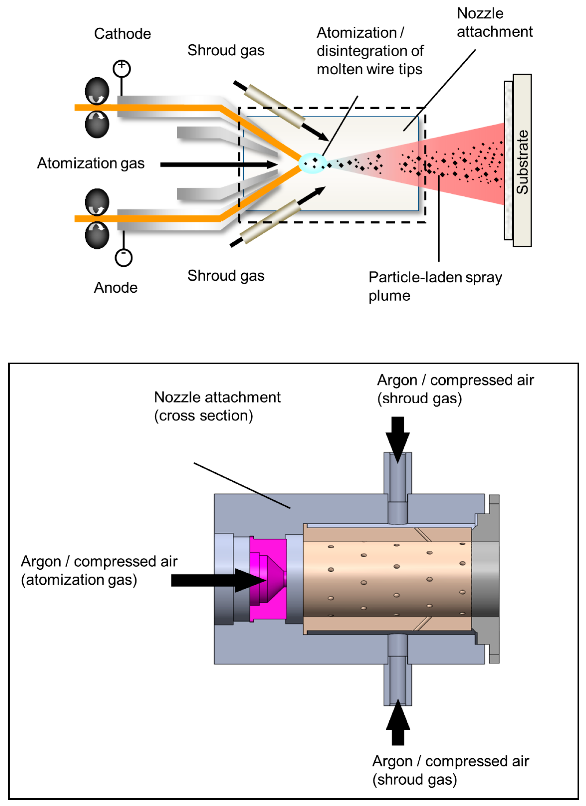
Arc spraying is a well-established process mainly used in surface refurbishments and maintenance applications, featuring comparatively low investment and operating costs, facilitated handling (including mobility), and extremely high energy efficiency at high deposition rates [19]. Arc-sprayed coatings typically exhibit a lamellar microstructure, high surface roughness, and tensile residual stresses. To meet the demands of the coated workpiece’s surface quality, arc-sprayed coatings are commonly subjected to a subsequent machining process. The lamellar microstructure results from the splashing and overlapping of individual spray particles and depends on the spray particle conditions at the moment of impact onto the substrate [20,21,22,23,24]. The generation of spray particles, i.e., the droplet formation, is determined by the aerodynamically driven disintegration of the molten electrode tips as well as the magnetofluid-dynamic processes and thus depends on the flow characteristics of the atomization gas, the thermodynamic properties and transport quantities (for partially ionized plasma in the area of arc discharge), as well as the physical properties of the electrodes (e.g., material-specific properties of the melt) [24,25,26,27,28]. Numerous studies have already dealt with the use of different atomizing gas types for the production of arc-sprayed coatings [22,29,30,31]. For different feedstocks, it was validated that the use of compressed air led to an increased oxide content in the deposits. The produced coatings are typically interstratified with miscellaneous oxides, which are formed between individual lamellae depending on their chemical composition [21,32,33]. The use of inert gases such as nitrogen or argon in combination with shrouds can reduce the oxide content [34,35,36,37,38,39]. Moreover, it was stated that the use of an inert gas atmosphere leads to the formation of coarser spray particles, which cause the formation of larger lamellae with an increased number of pores [40]. Due to the inherent process characteristics of arc spraying, the feedstock is heated above its melting point. This can result in a loss of alloying elements and phase transformation processes (e.g., tungsten carbide decomposition phenomena and formation of eta carbides [11,41,42]), whereby the latter depends on environmental conditions (atmospheric, inert) [30]. Distinct carbide decomposition phenomena, the formation of eta carbides, and oxide formation can lead to material embrittlement and thus impair the mechanical properties.
The deposition of thermally sprayed coatings is associated with the formation of residual stresses. Quenching stresses and thermal stresses are the two main sources contributing to the overall residual stresses [43]. For arc sprayed coatings, quenching stresses arise during the rapid solidification of molten droplets owing to the impingement onto the substrate or sublayer [44]. Constraining the thermal contraction of individual splats by adherence to the underlying material, results in tensile stresses within the splats [45,46]. As the cooling process continues (i.e., cooling down to ambient temperature), thermal stresses develop due to thermal expansion mismatch between the coating and substrate [45,46,47].
The presence of tensile or compressive residual stresses has a crucial impact on the coating’s performance. Thus, compressive residual stresses in the coating can contribute positively to the fatigue life of the coated component [45]. In contrast, tensile residual stresses can cause fatigue failure and cracking if their magnitude exceeds the yield strength of the material [45,48].
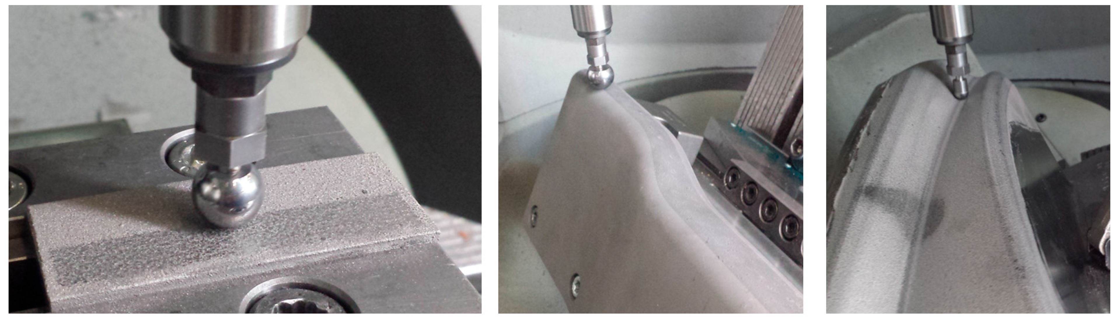
In the field of surface conditioning, the MHP represents a mechanical post-treatment that has already been applied in the tool- or mold-making industry in order to enhance the surface quality and life span of the tool [49,50]. For bulk materials (e.g., high-strength steel), it was demonstrated that the MHP leads to the introduction of compressive residual stresses in the near-surface area of the workpiece [51]. The MHP thus enables the potential to superimpose the tensile residual stresses, i.e., the inherent stress state, onto the machined surface with compressive residual stresses or adapt them locally. Conventional methods for reducing residual stresses, such as stress relief heat treatment, are only conditionally suitable for a broad range of tungsten carbide-based hard coatings and are not commonly used. Furthermore, as demonstrated for arc-sprayed metallic coatings (e.g., ZnAl coating), the MHP allows the densification of the coating’s microstructure [52] and reveals the potential to increase the fatigue and corrosion fatigue resistance of the coating-substrate composite [53,54]. Among others, hybrid process strategies such as thermally assisted MHP are also being investigated to increase the capabilities of the machining process [52]. Studying different MHP parameter settings using a statistical design of experiments, Rausch et al. [55] showed the great potential to smooth thermally sprayed hard coatings, i.e., high-velocity oxy-fuel sprayed WC-Co and arc sprayed WC-W2C-FeCMnSi coatings. Under optimized MHP parameter settings, the authors demonstrated the feasibility of optimizing the surface properties of a coated workpiece with complex geometry (Figure 1), which results in economic and technical advantages compared to subsequent machining processes.
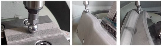
Figure 1.
MHP as a surface post-treatment for complex-shaped free form surfaces of tribologically stressed components.
Although the positive effect of the MHP on the surface integrity of arc sprayed coatings has been phenomenologically proven in various studies, the introduction of residual stresses in the near-surface area as well as the inclusion of strain hardening effects in arc sprayed coatings have been studied to a limited extent [55,56,57]. Within the scope of this study, the MHP was conducted on different arc-sprayed WC-W2C-FeCMnSi coatings that were deposited with the use of compressed air or argon as an inert gas. The surface integrity of the hammer-peened WC-W2C-FeCMnSi coatings was investigated with respect to their microstructural characteristics, such as porosity, lamellar structure, hardness, and residual stresses. The findings were compared to the results obtained from non-hammer-peened WC-W2C-FeCMnSi coatings, which served as references.
2. Materials and Methods
2.1. Substrate and Feedstock Material
Round (40 mm × 6 mm) steel specimens (material: AISI 1045) were used as substrate materials, which are used, e.g., for forming tools. The substrate surfaces were grit-blasted with corundum (type EKF 14, according to FEPA). Following this, the substrates were cleaned in an ultrasonic ethanol bath.
A FeCMnSi-cored wire (type Durmat AS-850, Fa. Durum Verschleißschutz, Willich, Germany) with cast tungsten carbides (CTC) as a filling, which consists of an eutectic WC-W2C mixture, served as feedstock. As verified by laser light scattering, the 50th percentile of the volumetric particle size distribution of sampling (i.e., WC-W2C filling) was nearly 113.2 µm, whereas the 10th and 90th percentiles of sampling were 72.8 µm, and 158.4 µm. The sampling features a bimodal particle size distribution with a small amount of WC-W2C particles in a range of a few microns. With regard to the wire configurations, the bandwidth and thickness of the velum were 10 mm and 220 µm, whereas the diameter of the wire was 1.6 mm. According to the manufacturer, the cored wire consists of 2 wt.% of C, 1.4 wt.% of Mn, 1.1 wt.% of Si, 48 wt.% of W, and bal. Fe.
2.2. Spray Parameter
The WC-W2C-FeCMnSi coatings were deposited on the steel substrates utilizing the arc spraying device Smart Arc 350 PPG spraying system (Fa. Oerlikon Metco, Wohlen, Switzerland). A commercially available front-end device (high-profile centering post, No. PPG5I976; air cap body (fine), No. PPG51416, Fa. Oerlikon Metco, Wohlen, Switzerland) and a prototypical nozzle attachment (Figure 2) were used within the scope of the experimental approach. For the coating deposition, two different gas types (compressed air and 99.99% pure argon) were used. For the axial incoming atomization gas, either argon or compressed air are used, whereas a secondary gas (argon or compressed air) serves as the shroud gas. The process parameter settings were kept constant for all experiments (atomization gas pressure = 1.2 MPa, secondary gas pressure = 0.6 MPa, voltage = 30 V, current = 220 A, spray distance = 110 mm, gun velocity = 200 mm/s, track pitch = 5 mm, two overruns).
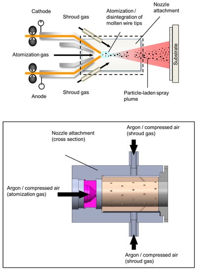
Figure 2.
Experimental setup showing the prototypical nozzle attachment to produce the different arc sprayed WC-W2C-FeCMnSi coatings.
2.3. Machine Hammer Peening Process
Prior to the MHP, the coated samples were machined by using silicon carbide grinding discs and polishing cloths with a diamond suspension (9 µm, 6 µm, 3 µm, and 1 µm). The subsequent MHP on the coated specimens was conducted on a five-axis milling machine type DMU50 eVolution (Fa. Deckel Maho, Pfronten, Germany) using a pneumatic MHP tool type Forge Fix Air (Fa. 3S-Engineering, Marktoberdorf, Germany) in a load-controlled mode. The MHP parameter settings were derived from preliminary tests using a design of experiments, as shown in [55], and were used in this study for the production of the samples. A spherically shaped tool tip made of cemented carbide (ball-tip diameter dk = 12 mm) was applied. The operating air pressure of the tool was adjusted to 0.6 MPa, resulting in an oscillating frequency of approximately f = 220 Hz. The feed velocity vf and the parallel path distance a of the meander-like movement were kept at constant values (vf = 1000 mm min−1, a = 0.2 mm). The MHP coating systems are referred to as Ar-MHP and CA-MHP, while the references are referred to as Ar-non-MHP and CA-non-MHP, respectively. The resulting machined surface conditions are summarized in Table 1.

Table 1.
MHP and non-MHP thermally sprayed samples used for the tribological investigation.
2.4. Analytics Methods
In order to examine the morphology of the WC-W2C-FeCMnSi coatings, cross-sections were taken and metallographically prepared using diamond grinding discs and polishing cloths with a diamond suspension (9 µm, 6 µm, 3 µm, and 1 µm). Cross-sectional images were taken using a field emission scanning electron microscope (FE-SEM) type JSM-7001F (Fa. JEOL, Tokyo, Japan) equipped with secondary electrons (SE) and backscattered electrons (BSE). In conjunction with the FE-SEM, energy dispersive X-ray spectroscopy (EDS) was conducted in order to determine the element distribution.
The coating porosity and lamella thickness were determined based on image analysis (Axiovision AutMess, Fa. Zeiss, Oberkochen, Germany) using SEM images with magnifications of 250×, and 350×, respectively. The lamella thickness was measured along the coating thickness at ten different spots. For each sample, 200 lamellae were measured in total.
The phase composition was investigated by means of X-ray diffraction analyses. The experiments were implemented at the beamline BL9 of the synchrotron light source DELTA (Dortmund Electron Accelerator, Dortmund, Germany). The incident photon energy was 13 keV, which corresponds to a wavelength λ of 0.9537 Å). The angle of incidence was set to 5 degrees, whereas the beam size was 0.2 × 1.0 mm2 (v × h). A PILATUS detector system (Fa. Dectris, Baden, Switzerland) was applied to measure the scattered intensity. Afterward, the 2-theta scale of the diffraction patterns was converted to a wavelength λ of 1.5406 Å.
To assess the potential of inducing strain hardening effects into the coating surface, the hardness was determined at the coating surface by means of nanoindentation load-displacement curves, as suggested by Oliver and Pharr [58], using the nanoindenter G200 (Fa. Agilent Technology, Santa Clara, CA, USA) equipped with a Berkovich indenter. The indents were carried out in penetration-control mode with a depth of two microns at regular intervals on a representative surface area. A total of 49 indents were performed for each sample. The nanoindents were accompanied by EDS spot analyses in order to evaluate the element concentration at the remaining indents, thus excluding single indents in carbidic hard phases (e.g., CTC particles) for calculations. In addition, Vickers microhardness tests were conducted at the coating surface with a load of 2.942 N utilizing the microhardness tester model M-400 (Fa. LECO, Mönchengladbach, Germany). Five indentations were performed for each sample. A light microscope (type Axiophot, Fa. Zeiss, Germany) was utilized to measure the diagonals of the remaining indents.
Moreover, scanning transmission electron microscopy (STEM) was executed to investigate the dislocation density. Prior to the STEM, sample preparation was carried out by focused Ga ion-beam preparation using the FEI Helios Nanolab 600 (Fa. Thermo Fisher Scientific, Waltham, WA, USA; former Fa. FEI Company, Peabody, MA, USA). The sampling of the coating surface was analyzed using the transmission electron microscope JEM-2200FS (Fa. JEOL, Tokyo, Japan), operating at an acceleration voltage of 200 kV. The samples were tilted inside the microscope to satisfy the excitation conditions for appropriate dislocation observation.
The hole drilling method (HDM) was applied to determine the through-thickness residual stress distribution in the coating using the RS-200 Milling Guide (Fa. Vishay Precision Group, Malvern, PA, USA, performed at the Institute of Forming Technology and Lightweight Components, TU Dortmund University). Initially, a strain gauge rosette with a diameter of 5.13 mm (type CEA-06-062UL-120, Fa. Vishay Intertechnology, Malvern, PA, USA) was mounted on the coated specimens. Orbital drilling with a drilling speed of 300,000 rpm was performed to remove the material using an end mill with 0.9 mm in diameter (type 806.314.009, Fa. Gebr. Brasseler, Lemgo, Germany). The drilling was executed up to a coating thickness of 200 µm with drilling steps of 10 μm. After each increment, the process was stopped and the strain was recorded by a computerized data acquisition system, LabVIEW (Fa. National Instruments, Austin, TX, USA). The residual stresses were calculated from the depth-dependent strains using the differential method. The shear and Young’s modulus were determined utilizing the impulse excitation technique, as shown in [59]. Accordingly, the Young’s modulus of the coating was estimated using Equation (1).
where is Young’s modulus of the substrate, I with the subscripts c and s for the coating and the substrate, respectively, is the area moment of inertia of the cross section with respect to the neutral axis. and mc+s indicate the length and mass of the entire specimen. is the resonance frequency of flexural vibration and can be written as (Equation (2)) [59,60]:
where is the density, and is the cross-sectional area of the respective components. To estimate the shear modulus of the coating , a free-standing coating was first separated from the substrate utilizing electrical discharge machining, followed by mechanical grinding. For a bar-shaped free-standing coating with a rectangular cross-section can be calculated as follows: see Equation (3) [61],
where l is the length, b is the width, h is the thickness, and m is the mass of the specimen. Here, represents the resonance frequency of torsional vibration. Since and have been calculated, the Poisson’s ratio of the coating can be determined using Equation (4) [62].
According to Equations (1)–(4), a Poisson’s ratio and Young’s modulus of the coating of = 0.30 and = 55 GPa, respectively, were estimated for sample CA-non-MHP. This value was taken into account for all other arc-sprayed CTC-reinforced Fe-based coatings examined within this study. For the AISI 1045 substrate, a Young’s modulus of 190 GPa was used [63].
3. Results and Discussion
Microstructure
SEM images show the cross section of the different CTC-reinforced Fe-based coatings (Figure 3). The BSE imaging demonstrates variation in brightness, indicating inhomogeneity in chemical composition. EDS analyses reveal that the coatings are formed from lamellar microstructures of Fe- and W-rich phases. Thus, W-rich phases (bright phases) scatter throughout the coatings and are unevenly distributed and surrounded by the Fe-based matrix (dark gray phases).
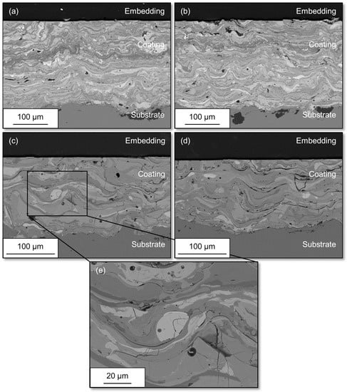
Figure 3.
Cross-sectional images measured by scanning electron microscopy depicting the coating morphology of different samples: (a) CA-MHP, (b) CA-non-MHP, (c) Ar-MHP, (d) Ar-non-MHP, and (e) enlarged view of Ar-MHP.
The cross-sectional analyses indicate the presence of fully fused W-rich hard particles. A small amount of not fully fused W-rich hard particles is sporadically observed. Those not fully fused W-rich hard phases contain a polygonal shape and correspond to the morphology of CTC particles in the filling.
Moreover, the cross-sectional analyses reveal a small number of pores and interlamellar cracks. The cracks predominantly pass horizontally parallel to the coating/substrate interface between individual lamellae or splats, with interlamellar cracks appearing more frequent in the sample Ar-non-MHP. Instead, the pores are randomly distributed across the different coatings.
According to the EDS analysis, the samples produced by using compressed air (i.e., CA-MHP and CA-non-MHP) contain 51.8 ± 0.7 wt.% of Fe, 37.7 ± 0.7 wt.% of W, 4.1 ± 0.8 wt.% of C, and 6.4 ± 0.2 wt.% of O on average. As opposed to that, the samples deposited using argon (i.e., Ar-MHP and Ar-non-MHP) consist of 54.5 ± 0.8 wt.% of Fe, 35.5 ± 0.7 wt.% of W, 5.5 ± 0.2 wt.% of C, and 4.6 ± 0.3 wt.% of O on average. It can be noted that all samples exhibit a certain amount of oxides, with a reduced amount of oxides being observed for the samples Ar-MHP and Ar-non-MHP. However, when compared to the nominal composition of the fabricated cored wire, some carbide loss was determined as a reduced amount of W was observed in the deposits. As previously reported in [64], one possible reason could be that a reduced amount of W-rich spray particles impinges onto the substrate, either due to an amended trajectory of some particles or a rebound of not fully fused CTC particles.
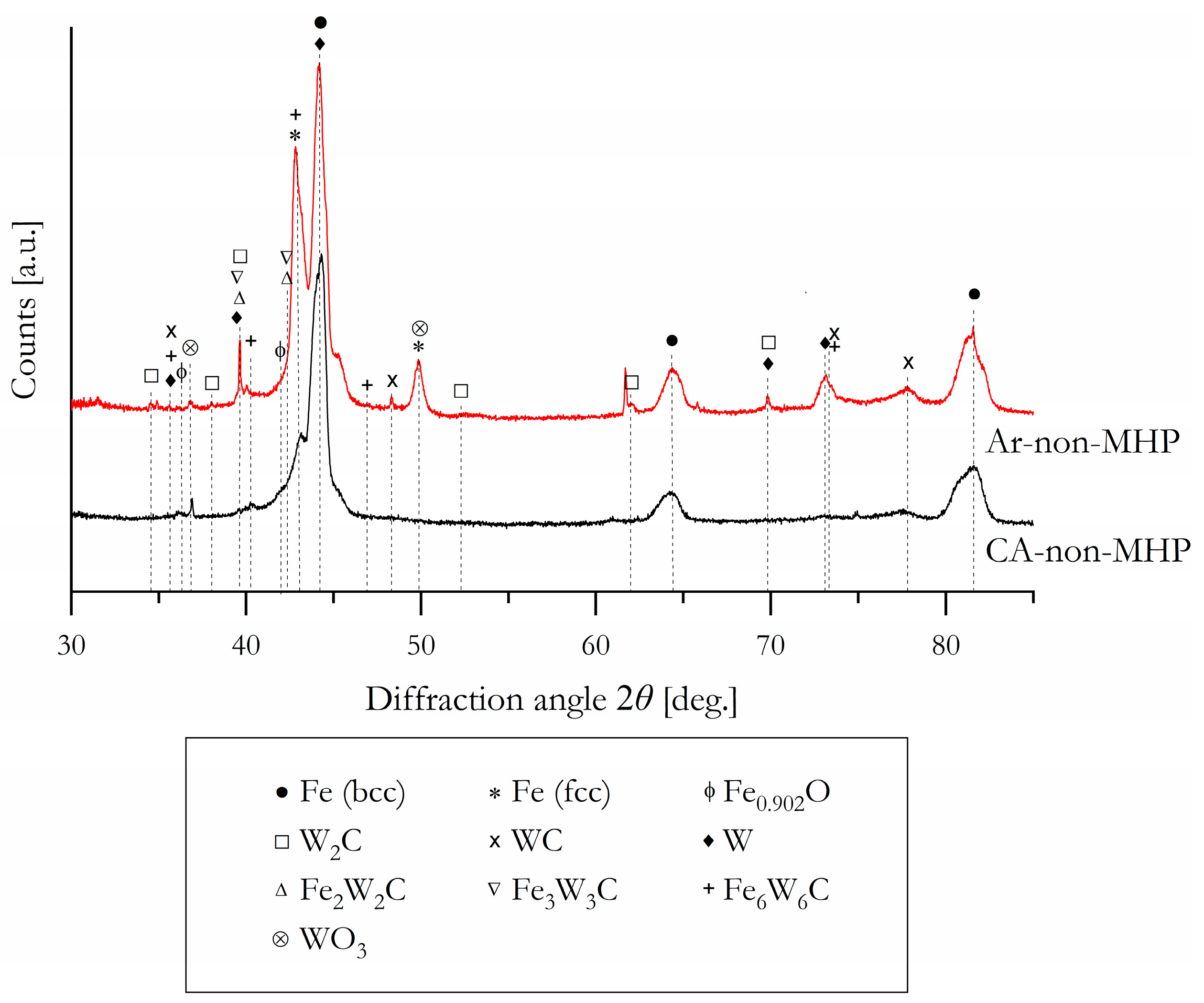
With regard to the XRD patterns obtained from the different samples prepared by either using compressed air or argon, it is found that the deposits are mainly composed of cubic Fe, eutectic carbides (WC and W2C), eta carbides (Fe2W2C, Fe3W3C, Fe6W6C), elementary W, as well as some traces of various oxides such as WO3 and Fe0.902O (Figure 4). Regarding the cored wire, which served as feedstock, the sheath is mainly composed of cubic Fe, whereas the filling contains WC and W2C. Along with the major peaks of Fe, a peak broadening can be observed for the arc-sprayed deposits, which is most likely attributable to an amorphous/nanocrystalline structure. Due to the rapid solidification (about ~105 °C/s) [22] of molten spray particles, arc spraying has great potential for the production of amorphous coatings, as already demonstrated in [65,66] for Fe-based coatings. Nevertheless, the Bragg reflections suggest a crystalline structure.
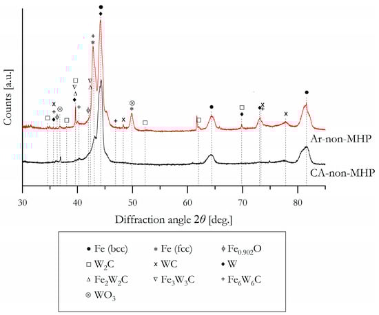
Figure 4.
XRD pattern obtained from the arc-sprayed CTC reinforced Fe-based coatings produced with the use of different atomization gases.
It is striking to note that a certain oxide content was detected for the arc-sprayed samples, although argon was used as atomization and shroud gas. Since an oxidizing environment prevails, it can be assumed that the oxides were generated during atomization of the molten electrodes (i.e., the molten wire tips), acceleration of spray particles towards the substrate, or splashing onto the substrate. The kinetics of interactions of arc-sprayed particles (i.e., atomized metal droplets) with oxygen were discussed by Boronenkov and Korobov [28], who developed a physical model of oxygen delivery to a droplet. As reported by the authors, although the solubility limit of oxygen in the liquid metal at the electrode tips and in the arc burning zone is significantly higher than during flight due to higher temperatures, oxygen uptake in spray particles during flight or splashing onto the substrate is possible.
Nevertheless, for arc-sprayed coatings, phase transformation processes result in a wide range of non-equilibrium states because of inherent process characteristics such as constitutional supercooling during rapid solidification of spray particles. In consequence, the phases can be determined only to a limited extent within the experimental resolution.
By analyzing the morphological properties of the specimens, it is clearly visible that a distinct compression of the coating due to the MHP can be precluded. Instead, only a slight reduction in porosity and lamella thickness can be observed for the MHP-treated specimens, which can be attributed to mechanically induced plastic deformation. Based on the image analysis, the MHP-treated sample Ar-MHP shows a porosity of 3.8 ± 0.7%, whereas the sample Ar-non-MHP exhibits a porosity of 6.3 ± 1.7% (Table 2). The same tendency can be noted for the samples deposited using compressed air; however, the differences in porosity are rather marginal. Thus, the sample CA-MHP demonstrates a porosity of 2.2 ± 0.4%, while the sample CA-non-MHP features a porosity of 2.7 ± 0.3%.
Table 2.
Microstructural characteristics and mechanical properties obtained from the different samples (mean values).
Figure 5 shows the relative frequency distribution of the measured lamellae depending on the lamella thickness.
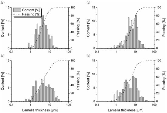
Figure 5.
Relative frequency distribution of the measured lamellae depending on the lamella thickness obtained from image analysis: (a) CA-MHP, (b) CA-non-MHP, (c) Ar-MHP, and (d) Ar-non-MHP. The dashed line indicates the cumulative relative frequency.
The frequencies reveal a nearly bimodal distribution, each of which has a maximum at a lamella thickness of approximately 10 µm, or, in the lower lamella thickness range, less than 5 µm. A homogeneous Gaussian distribution is not recognizable.
The relative frequency distributions reveal a decreasing lamella thickness for the MHP-treated samples, i.e., CA-MHP (Figure 5a) and Ar-MHP (Figure 5c). Based on the measurements, sample Ar-MHP possesses a mean lamella thickness of 6.4 ± 5.6 µm (Table 2). In contrast, sample Ar-non-MHP reveals a mean lamella thickness of 6.8 ± 5.7 µm. A mean lamella thickness of 5.0 ± 3.3 µm could be measured for the compressed air-sprayed and MHP-treated sample CA-MHP, whereas a mean lamella thickness of 7.5 ± 6.3 µm could be determined for the reference sample CA-non-MHP.
The findings indicate the densification of the coating microstructure as a consequence of the MHP. It is assumed that splats across the coating thickness are plastically deformed due to the MHP, leading to reduced lamella thickness and the number of pores. However, in contrast to the positive effects, the formation of vertical cracks could also be observed. Cracks are formed and propagate through individual lamellae, hard phases, and along splat boundaries (i.e., between individual lamellae) since the frequently occurring MHP induces brittle fractures instead of plastic deformations.
In terms of the mechanical properties, an increase in Vickers microhardness (or hardness (H) taken by nanoindentation) can be found at the surface area of the MHP-treated samples (Table 2). Accordingly, the sample CA-MHP shows a Vickers microhardness of 752 ± 152 HV0.5 (H = 5.6 ± 1.3 GPa), whereas the sample CA-non-MHP demonstrates a Vickers microhardness of 621 ± 121 (H = 5.1 ± 1.6 GPa). The same tendency can be found for the samples Ar-MHP and Ar-non-MHP. Here, sample Ar-MHP features a Vickers microhardness of 711 ± 272 HV0.5 (H = 5.6 ± 2.1 GPa). In contrast, sample Ar-non-MHP possesses a Vickers microhardness of 604 ± 208 HV0.5 (H = 5.1 ± 2.4 GPa).
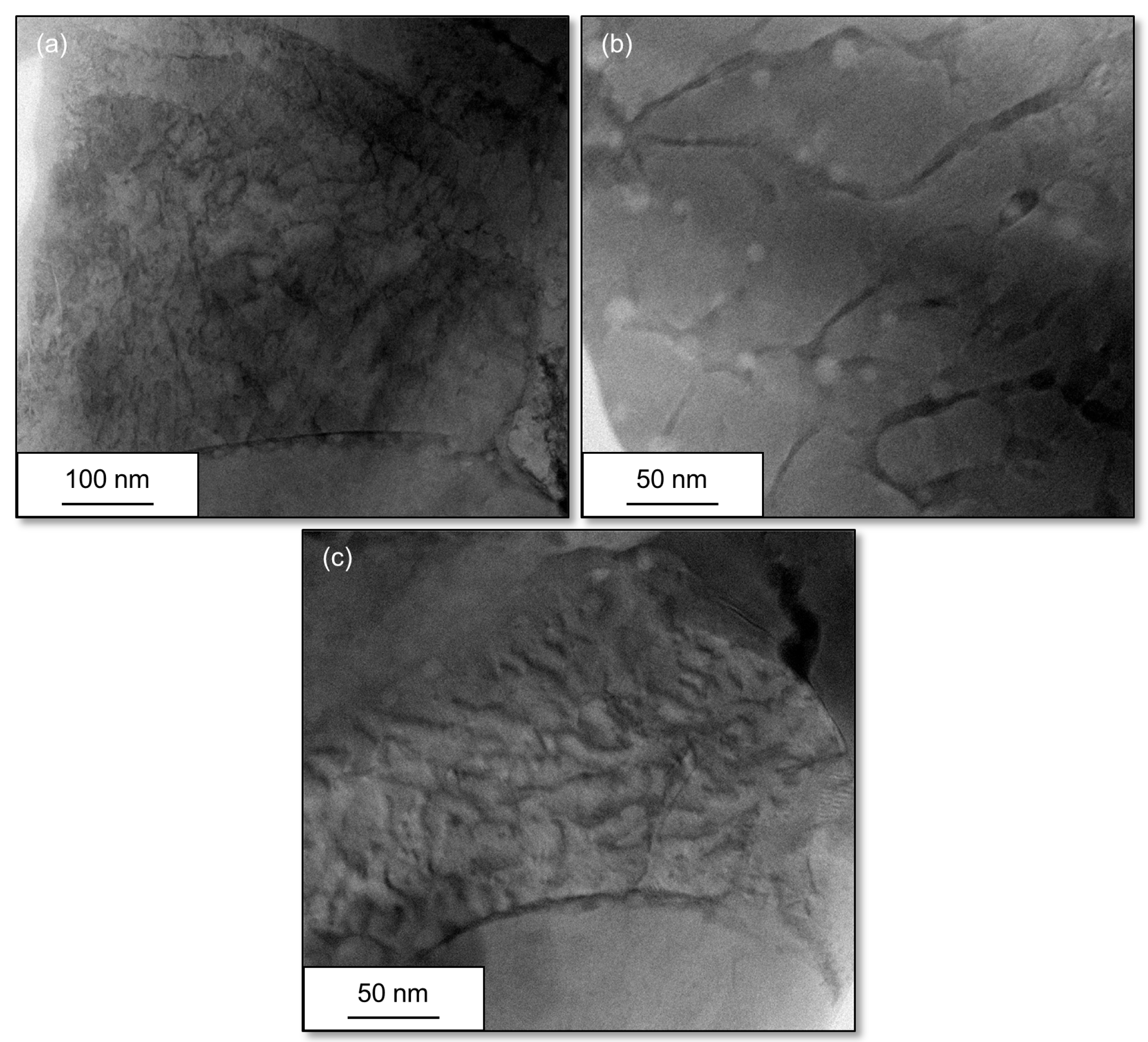
Evaluating the microstructural characteristics of the different post-treated samples using scanning transmission electron microscopy (Figure 6 and Figure 7), it is found that the MHP-treated surfaces, i.e., samples CA-MHP and Ar-MHP, possess isolated and locally deformed grain structures with a high amount of dislocations in their structures (see black lines in Figure 6a,c, and Figure 7a,c).

Figure 6.
STEM bright-field micrographs showing the representative surfaces of the different samples: (a,c) CA-MHP; (b) CA-non-MHP.
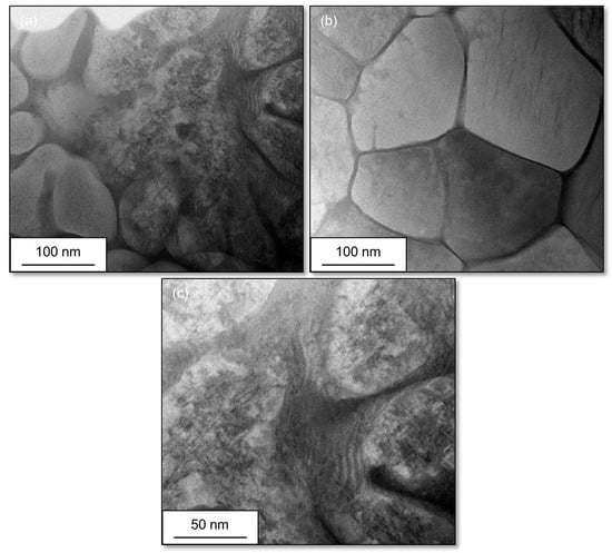
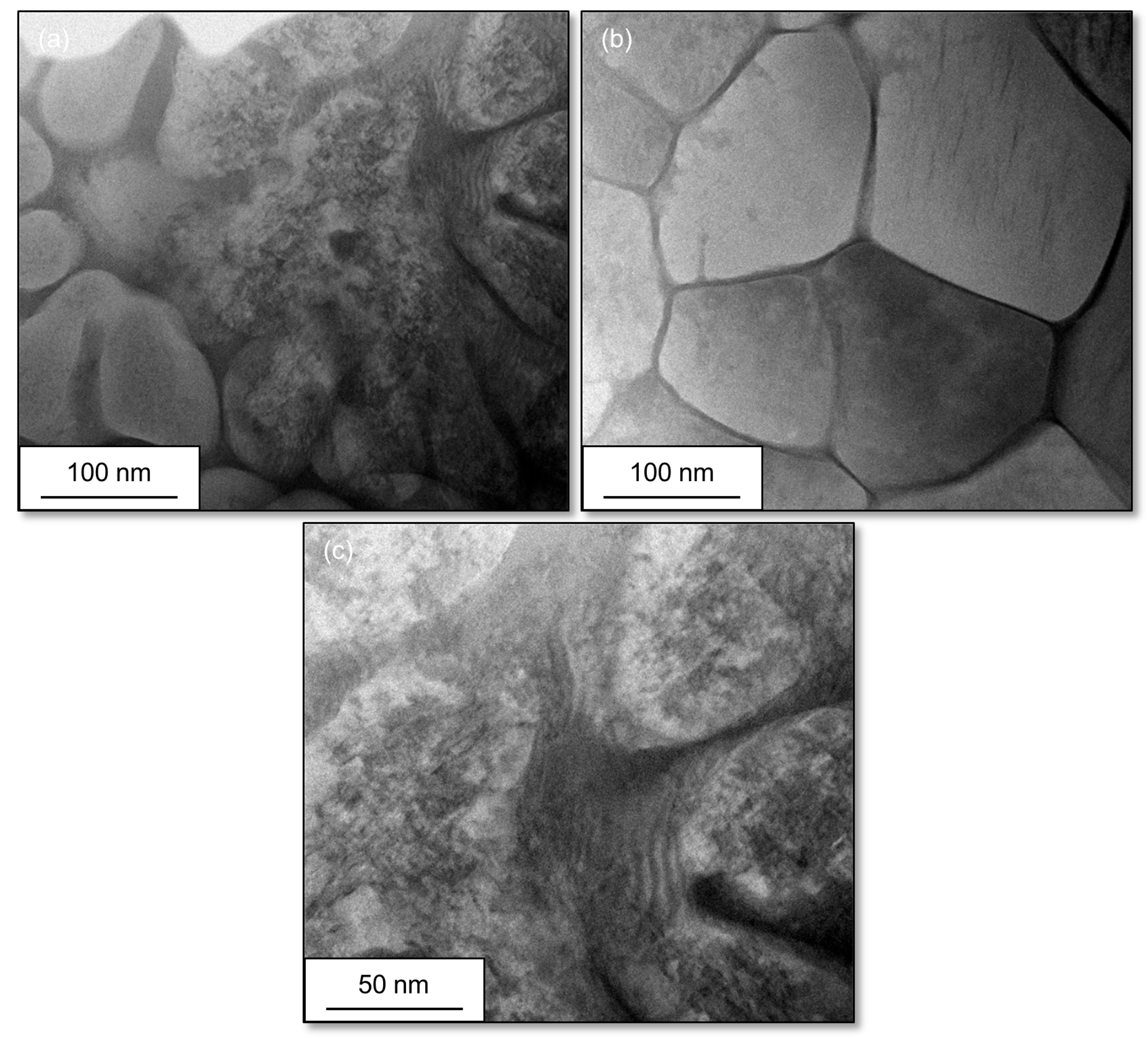
Figure 7.
STEM bright-field micrographs showing the representative surfaces of the different samples: (a,c) Ar-MHP; (b) Ar-non-MHP.
Besides a high number of dislocations, some accumulations of dislocations or arrays of dislocation walls are observed (see the black area in Figure 6a). With regard to the sample Ar-MHP, the STEM image also reveals the presence of shear bands (i.e., a line-like structure, Figure 7c). The assumption that grain refinement results from high plastic deformation while coarser grains are located at the less deformed grains applies to individual regions of interest but cannot be confirmed in general within this study.
For the MHP-treated surfaces, the STEM images verify an increased number of dislocations, an array of dense dislocation walls, and the presence of shear bands, suggesting high plastic strain and, hence, a high level of localized grain deformation on the impacts after MHP. Consequently, the high level of plastic deformation causes strain hardening effects in the coating surfaces, thus leading to an increased Vickers microhardness, or hardness, respectively (Table 2).
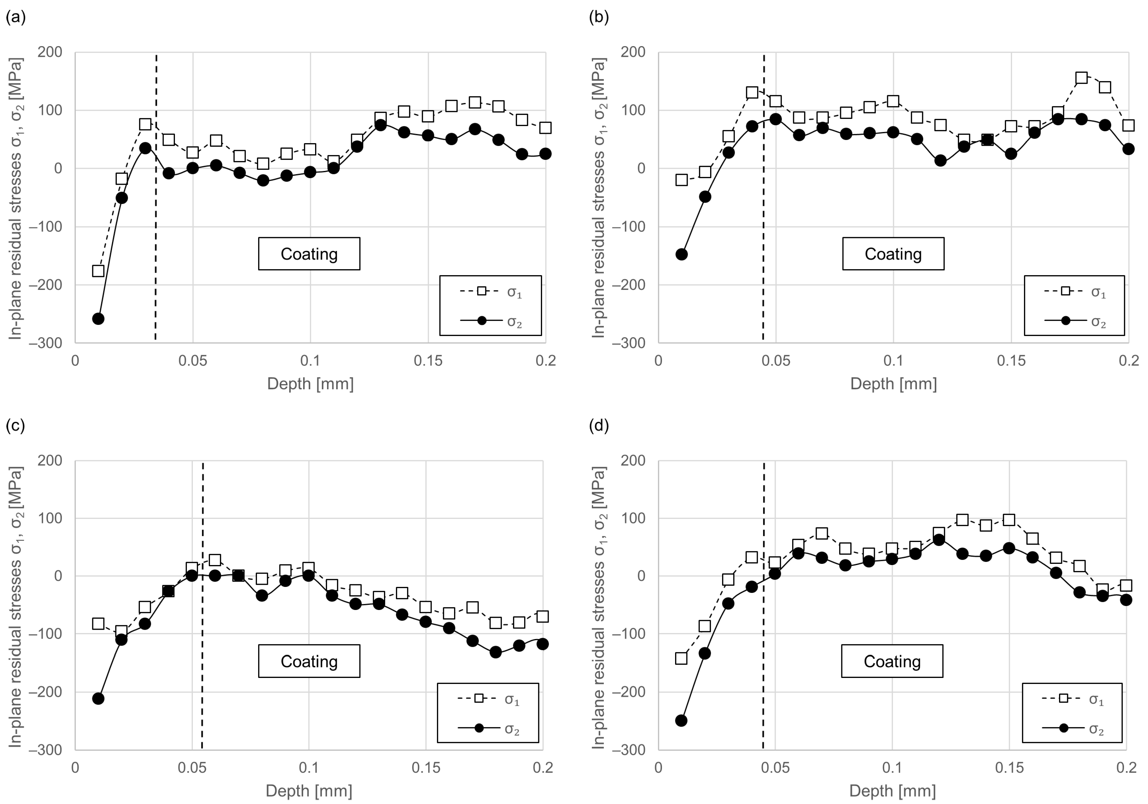
Figure 8 shows the through-thickness distribution of the in-plane residual stresses (σ1 and σ2 [67]) in the coatings. The coating thickness was determined by metallographic investigations using image analysis. The adhesive used to attach the strain gauge to the coating is sufficiently strong to affect the deformation of the strain-sensitive element in the strain gauge, which subsequently influences the output from the gauge [68]. Accordingly, the first few microns at the subsurface area were separated and not taken into account (see dashed line).
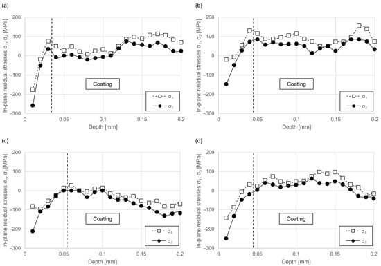
Figure 8.
Residual stress measurement showing the in-plane residual stresses obtained from the BDM for different samples: (a) CA-MHP, (b) CA-non-MHP, (c) Ar-MHP, and (d) Ar-non-MHP.
As obtained from the HDM, the arc-sprayed CTC-reinforced Fe-based coatings exhibit a non-uniform residual stress distribution. The non-uniform evolution of stress is characterized by several peaks, some of which show a sinusoidal shape. The non-MHP-treated coatings predominantly exhibit tensile residual stresses (Figure 8b,d). With growing coating thickness going towards the substrate, the HDM reveals a stress gradient partly towards higher values and partly towards lower values. Therefore, a clear tendency could not be determined. However, a stress gradient next to the coating-substrate interface going from tensile to compressive at the substrate subsurface area could be noticed.
When comparing the different samples, it is found that the MHP-treated samples exhibit lower tensile residual stresses at the near-surface area (Figure 8a,c). Occasionally, a decline in tensile residual stresses towards compressive values can be observed. The formation of compressive residual stresses of higher orders of magnitude, however, cannot be obtained from the MHP-treated samples. It can be assumed that the MHP leads to the introduction of compressive residual stresses at the near-surface area and thus contributes to the overall residual stresses.
4. Conclusions
This study aimed at evaluating the machine hammer peening on arc-sprayed WC-W2C-FeCMnSi coatings and its effect on the coating porosity, lamellar structure, hardness, and residual stresses. The examinations were carried out on different coating types that were deposited using either argon or compressed air as atomization and shroud gases. Both coating types exhibit a certain amount of various oxides distributed across the coating, with a reduced amount of oxides being observed for the coating produced using argon as atomization and shroud gas. The different coatings are mainly composed of cubic Fe, WC, W2C, eta carbides (Fe2W2C, Fe3W3C, and Fe6W6C), elementary W, as well as some traces of WO3 and Fe0.902O. Applying the machine hammer peening to the different coating types, the following conclusions can be drawn:
The machine hammer peeing leads to:
- a reduced porosity and lamella thickness due to a densification of the coating microstructure
- an increased hardness due to strain hardening effects based on the formation of dislocations
- an additional introduction of compressive residual stresses which contributes to a decline in tensile residual stresses in the near-surface area
In contrast to the positive effects, the machine hammer peeing also shows the formation of vertical cracks. These cracks are formed and propagated through individual lamellae, hard phases, and splat boundaries.
Author Contributions
Conceptualization, L.H.; investigation, L.H. and M.H.; writing—original draft preparation, L.H., J.B. and M.H.; writing—review and editing, L.H. and J.B.; supervision, W.T. and D.B.; project administration, L.H.; funding acquisition, W.T. and D.B.; All authors have read and agreed to the published version of the manuscript.
Funding
This research was funded by the DFG (German Research Foundation) within the Collaborative Research Centre SFB 708 3D-Surface Engineering of Tools for Sheet Metal Forming-Manufacturing, Modeling, Machining (16071898).
Institutional Review Board Statement
Not applicable.
Informed Consent Statement
Not applicable.
Data Availability Statement
Data sharing is not applicable to this article.
Acknowledgments
The authors gratefully acknowledge the DELTA machine group for providing synchrotron radiation.
Conflicts of Interest
The authors declare no conflict of interest.
References
- Shipway, P.H.; McCartney, D.G.; Sudaprasert, T. Sliding Wear Behaviour of Conventional and Nanostructured HVOF Sprayed WC–Co Coatings. Wear 2005, 259, 820–827. [Google Scholar] [CrossRef]
- Espallargas, N.; Berget, J.; Guilemany, J.M.; Benedetti, A.V.; Suegama, P.H. Cr3C2–NiCr and WC–Ni Thermal Spray Coatings as Alternatives to Hard Chromium For Erosion-Corrosion Resistance. Surf. Coat. Technol. 2008, 202, 1405–1417. [Google Scholar] [CrossRef]
- Nahvi, S.M.; Jafari, M. Microstructural and Mechanical Properties of Advanced HVOF-Sprayed WC-Based Cermet Coatings. Surf. Coat. Technol. 2016, 286, 95–102. [Google Scholar] [CrossRef]
- Sánchez, E.; Bannier, E.; Salvador, M.D.; Bonache, V.; García, J.C.; Morgiel, J.; Grzonka, J. Microstructure and Wear Behavior of Conventional and Nanostructured Plasma-Sprayed WC-Co Coatings. J. Therm. Spray Tech. 2010, 19, 964–974. [Google Scholar] [CrossRef]
- Berghaus, J.O.; Marple, B.; Moreau, C. Suspension Plasma Spraying of Nanostructured WC-12Co Coatings. J. Therm. Spray Technol. 2006, 15, 676–681. [Google Scholar] [CrossRef]
- He, D.J.; Fu, B.J.; Jiang, J.M.; Li, X.J. Microstructure and wear performance of arc sprayed Fe-FeB-WC coatings. J. Therm. Spray Technol. 2008, 17, 757–761. [Google Scholar] [CrossRef]
- Tillmann, W.; Klusemann, B.; Nebel, J.; Svendsen, B. Analysis of the mechanical properties of an arc-sprayed WC-FeCSiMn coating: Nanoindentation and simulation. J. Therm. Spray Technol. 2011, 20, 328–335. [Google Scholar] [CrossRef]
- Tillmann, W.; Luo, W.; Nebel, J. Einfluss der Hartstoffkorngröße auf die tribologischen Eigenschaften gewalzter und geschliffener WSC-FeCSiMn-Schichten. Therm. Spray Bull. 2011, 4, 56–63. [Google Scholar]
- Tillmann, W.; Luo, W.; Selvadurai, U. Wear analysis of thermal spray coatings on 3D surfaces. J. Therm. Spray Technol. 2014, 23, 245–251. [Google Scholar] [CrossRef]
- Xu, B.; Zhu, Z.; Ma, S.; Zhang, W.; Liu, W. Sliding wear behavior of Fe–Al and Fe–Al/ WC coatings prepared by high velocity arc spraying. Wear 2004, 257, 1089–1095. [Google Scholar] [CrossRef]
- Sheppard, P.; Koiprasert, H. Effect of W dissolution in NiCrBSi–WC and NiBSi–WC arc sprayed coatings on wear behaviors. Wear 2014, 317, 194–200. [Google Scholar] [CrossRef]
- Niranatlumpong, P.; Koiprasert, H. Phase transformation of NiCrBSi–WC and NiBSi–WC arc sprayed coatings. Surf. Coat. Technol. 2011, 206, 440–445. [Google Scholar] [CrossRef]
- Atteridge, D.G.; Davis, R.; Scholl, M.; Tewksbury, G. Twin wire arc and high energy plasma spray coating using nanometer scale WC-Co in powder-filled cored wire. J. Therm. Spray Technol. 2001, 10, 176–177. [Google Scholar]
- U.S. Department of Health and Human Services. Report on Carcinogens, Background Document for Metallic Nickel and Certain Nickel Alloys. Available online: https://ntp.niehs.nih.gov/ntp/newhomeroc/roc10/ni_no_appendices_508.pdf (accessed on 8 June 2023).
- No 790/2009. Commission Regulation (EC). Amending, for the Purposes of Its Adaptation to Technical and Scientific Progress, Regulation (EC) No 1272/2008 of the European Parliament and of the Council on classification, labelling and packaging of substances and mixtures. Official Journal of the European Union L235/1 (5.9.2009). Available online: https://eur-lex.europa.eu/legal-content/EN/TXT/PDF/?uri=CELEX:32009R0790&from=EN (accessed on 8 June 2023).
- Zimmermann, S.; Gries, B.; Fischer, J.; Lugscheider, E. (Eds.) Thermal Spray 2008: Crossing Borders. In Proceedings of the International Thermal Spray Conference, Maastricht, The Netherlands, 2–4 June 2008; DVS Deutscher Verband für Schweißen: Düsseldorf, Germany, 2008. [Google Scholar]
- U.S. Department of Health and Human Services. Cobalt–Tungsten Carbide: Powders and hard metals. In Proceedings of the 12th Report on Carcinogens, Chapel Hill, NC, USA, 9–10 December 2008; Available online: https://ntp.niehs.nih.gov/ntp/roc/twelfth/2008/expertpanelmtgs/cobalt_panelreportpartb_508.pdf (accessed on 8 June 2023).
- Scrivani, A.; Antolotti, N.; Bertini, S.; Groppetti, R.; Gutema, T.; Mangia, A.; Mucchino, S.; Viola, G.; Coddet, C. (Eds.) A Contribution to Methodology and Protocol Definition for Thermal Spray Coated Surface Compatibility Analysis in Food Processing Applications. In Proceedings of the Thermal Spray: Meeting the Challenges of the 21st Century, Nice, France, 25–29 May 1998; ASM International: Almere, The Netherlands, 1998; p. 1019. [Google Scholar]
- Abkenar, A.H.P. Wire-Arc Spraying System: Particle Production, Transport, and Deposition; Library and Archives Canada, Library and Archives Canada, University of Toronto: Toronto, ON, Canada, 2007. [Google Scholar]
- Pourmousa, A.; Mostaghimi, J.; Abedini, A.; Chandra, S. Particle Size Distribution in a Wire-Arc Spraying System. J. Therm. Spray. Tech. 2005, 14, 502–510. [Google Scholar] [CrossRef]
- Planche, M.P.; Liao, H.; Coddet, C. Relationships between InFlight Particle Characteristics and Coating Microstructure with a Twin Wire Arc Spray Process and Different Working Conditions. Surf. Coat. Technol. 2004, 182, 215–226. [Google Scholar] [CrossRef]
- Newbery, A.P.; Grant, P.S.; Neiser, R.A. The Velocity and Temperature of Steel Droplets during Electric Arc Spraying. Surf. Coat. Technol. 2005, 195, 91–101. [Google Scholar] [CrossRef]
- Liao, H.L.; Zhu, Y.L.; Bolot, R.; Coddet, C.; Ma, S.N. Size Distribution of Particles from Individual Wires and the Effects of Nozzle Geometry in Twin Wire Arc Spraying. Surf. Coat. Technol. 2005, 200, 2123–2130. [Google Scholar] [CrossRef]
- Hussary, N.A.; Heberlein, J.V.R. Effect of System Parameters on Metal Breakup and Particle Formation in the Wire Arc Spray Process. J. Therm. Spray. Tech. 2007, 16, 140–152. [Google Scholar] [CrossRef]
- Kelkar, M.; Heberlein, J. Wire-Arc Spray Modeling. Plasma Chem. Plasma Process. 2002, 22, 1–25. [Google Scholar] [CrossRef]
- Hussary, N.A.; Heberlein, J.V.R. Atomization and Particle-Jet Interactions in the Wire-Arc Spraying Process. J. Therm. Spray Tech. 2001, 10, 604–610. [Google Scholar] [CrossRef]
- Fang, J.J.; Li, Z.X.; Qian, M.; Ren, C.L.; Shi, Y.W. Effects of powder size in cored wire on arc-sprayed metal-ceramic coatings, global coating solutions. In Proceedings of the 2007 International Thermal Spray Conference, Beijing, China, 14–16 May 2007; Marple, B.R., Ed.; ASM International: Almere, The Netherlands, 2007; pp. 365–370. [Google Scholar]
- Boronenkov, V.; Korobov, Y. Fundamentals of Arc Spraying; Springer International Publishing: Berlin/Heidelberg, Germany, 2016. [Google Scholar]
- Paczkowski, G.; Rupprecht, C.; Wielage, B. Hochgeschwindigkeitslichtbogenspritzen—Die Renaissance eines Beschichtungsverfahrens. Therm. Spray Bull. 2012, 5, 140–147. [Google Scholar]
- Newbery, A.P.; Grant, P.S. Oxidation during Electric Arc Spray Forming of Steel. J. Mater. Process. Technol. 2006, 178, 259–269. [Google Scholar] [CrossRef]
- Zurecki, Z.; Garg, D.; Bowe, D. Electric arc deposition of carbon steel coatings with improved mechanical properties. J. Therm. Spray Technol. 1997, 6, 417–421. [Google Scholar] [CrossRef]
- Gedzevicius, I.; Valiulis, A.V. Analysis of Wire Arc Spraying Process Variables on Coatings Properties. J. Mater. Process. Technol. 2006, 175, 206–211. [Google Scholar] [CrossRef]
- Jandin, G.; Liao, H.; Feng, Z.Q.; Coddet, C. Correlations between Operating Conditions, Microstructure and Mechanical Properties of Twin Wire Arc Sprayed Steel Coatings. Mater. Sci. Eng. A 2003, 349, 298–305. [Google Scholar] [CrossRef]
- Hauer, M.; Banaschik, R.; Kroemmer, W.; Henkel, K.M. Variation of Heat Input and Its Influence on Residual Stresses and Coating Properties in Arc Spraying with Different Gas Mixtures. J. Therm. Spray Technol. 2019, 28, 40–52. [Google Scholar] [CrossRef]
- Sakoda, N.; Hida, M.; Takemoto, Y.; Sakakibara, A.; Tajiri, T. Influence of atomization gas on coating properties under Ti arc spraying. Mater. Sci. Eng. 2003, 264–269. [Google Scholar] [CrossRef]
- Wang, X.; Heberlein, J.; Pfender, E.; Gerberich, W. Effect of nozzle configuration, gas pressure, and gay type on coating properties in wire arc spray. J. Therm. Spray Technol. 1999, 8, 565–575. [Google Scholar] [CrossRef]
- Fussel, P.S.; Kirchner, H.O.K.; Prinz, F.B.; Weiss, L.E. Controlled microstructure of arc-sprayed metal shells. J. Therm. Spray Technol. 1994, 3, 148–161. [Google Scholar] [CrossRef]
- Daillaire, S.; Levert, H. Synthesis and deposition of TiB2-containing materials by arc spraying. Surf. Coat. Technol. 1992, 50, 241–248. [Google Scholar] [CrossRef]
- Milewski, W.; Sartowski, M. Some properities of coatings arc-sprayed in nitrogen or argon atmosphere. In Advances in Thermal Spraying; Pergamon Press: Oxford, UK, 1986; pp. 467–473. [Google Scholar]
- Steffens, H.D. Thermisches Spritzen von Stahlwerkstoffen in Schutzgasatmosphäre; Habilitationsschrift, Technische Universität Hannover: Hannover, Germany, 1967. [Google Scholar]
- Tillmann, W.; Abdulgader, M. Wire Composition: Its Effect on Metal Disintegration and Particle Formation in Twin-Wire Arc-Spraying Process. J. Therm. Spray Tech. 2013, 22, 352–362. [Google Scholar] [CrossRef]
- Tillmann, W.; Hagen, L.; Kokalj, D. Embedment of eutectic tungsten carbides in arc sprayed steel coatings. Surf. Coat. Technol. 2017, 331, 153–162. [Google Scholar] [CrossRef]
- Kuroda, S.; Clyne, T.W. The Quenching Stress in Thermally Sprayed Coatings. Thin Solid Film. 1991, 200, 49–66. [Google Scholar] [CrossRef]
- Chen, Y.; Liang, X.; Liu, Y.; Xu, B. Prediction of Residual Stresses in Thermally Sprayed Steel Coatings Considering the Phase Transformation Effect. Mater. Des. 2010, 31, 3852–3858. [Google Scholar] [CrossRef]
- Matejicek, J.; Sampath, S. Intrinsic Residual Stresses in Single Splats Produced by Thermal Spray Processes. Acta Mater. 2001, 49, 1993–1999. [Google Scholar] [CrossRef]
- Pina, J.; Dias, A.; Lebrun, J. Study by X-Ray Diffraction and Mechanical Analysis of the Residual Stress Generation during Thermal Spraying. Mater. Sci. Eng. A 2003, 347, 21–31. [Google Scholar] [CrossRef]
- Weglewski, W.; Basista, M.; Manescu, A.; Chmielewski, M.; Pietrzak, K.; Schubert, T. Effect of Grain Size on Thermal Residual Stresses and Damage in Sintered Chromium-Alumina Composites: Measurement and Modeling. Compos. B Eng. 2014, 67, 119–124. [Google Scholar] [CrossRef]
- Santana, Y.Y.; La Barbera-Sosa, J.G.; Staia, M.H.; Lesage, J.; Puchi-Cabrera, E.S.; Chicot, D.; Bemporad, E. Measurement of Residual Stress in Thermal Spray Coatings by the Incremental Hole Drilling Method. Surf. Coat. Technol. 2006, 201, 2092–2098. [Google Scholar] [CrossRef]
- Scheil, J.; Müller, C.; Steitz, M.; Groche, P. Influence of process parameters on surface hardening in hammer peening and deep rolling. Key Eng. Mater. 2013, 554–557, 1819–1827. [Google Scholar] [CrossRef]
- Wied, J. Oberflächenbehandlung von Umformwerkzeugen Durch Festklopfen; TU Darmstadt: Darmstadt, Germany, 2011. [Google Scholar]
- Tai, M.; Miki, C.; Suzuki, K. Mechanism of Fatigue Strength Improvement by Applying Peening Treatment. Procedia Eng. 2011, 14, 117–125. [Google Scholar] [CrossRef]
- Wirtz, A.; Abdulgader, M.; Milz, M.P.; Tillmann, W.; Walther, F.; Biermann, D. Thermally assisted machine hammer peening of arc-sprayed ZnAl-based corrosion protective coatings. J. Manuf. Mater. Process. 2021, 5, 109. [Google Scholar] [CrossRef]
- Milz, M.P.; Wirtz, A.; Abdulgader, M.; Biermann, D.; Tillmann, W.; Walther, F. Fatigue Assessment of Twin Wire Arc Sprayed and Machine Hammer-Peened ZnAl4 Coatings on S355 JRC + C Substrate. Materials 2022, 15, 1182. [Google Scholar] [CrossRef] [PubMed]
- Milz, M.P.; Wirtz, A.; Abdulgader, M.; Kalenborn, A.; Biermann, D.; Tillmann, W.; Walther, F. Corrosion Fatigue Behavior of Twin Wire Arc Sprayed and Machine Hammer-Peened ZnAl4 Coatings on S355 J2C + C Substrate. Corros. Mater. Degrad. 2022, 3, 127–141. [Google Scholar] [CrossRef]
- Rausch, S.; Wiederkehr, P.; Biermann, D. Machine Hammer Peening of Wear Resistant Thermally Sprayed Coatings. In Proceedings of the 12th International Conference THE ‘‘A’’ Coatings, Hannover, Germany, 31 March–1 April 2016; pp. 115–121. [Google Scholar]
- Rausch, S.; Wiederkehr, P.; Biermann, D.; Zabel, A.; Selvadurai, U.; Hagen, L.; Tillmann, W. Influence of machine hammer peening on the tribological behavior and the residual stresses of wear resistant thermally sprayed coatings. Procedia CIRP 2016, 45, 275–278. [Google Scholar] [CrossRef]
- Tillmann, W.; Hagen, L.; Schröder, P. Investigation on the tribological behavior of arc-sprayed and hammer-peened coatings using tungsten carbide cored wires. J. Therm. Spray Technol. 2017, 26, 229–242. [Google Scholar] [CrossRef]
- Oliver, W.C.; Pharr, G.M. An Improved Technique for Determining Hardness and Elastic Modulus Using Load and Displacement Sensing Indentation Experiments. J. Mater. Res. 1992, 7, 1564–1583. [Google Scholar] [CrossRef]
- Tillmann, W.; Selvadurai, U.; Luo, W. Measurement of the Young’s Modulus of Thermal Spray Coatings By Means of Several Methods. J. Therm. Spray Technol. 2013, 22, 290–298. [Google Scholar] [CrossRef]
- Chiu, C.C.; Case, E.D. Elastic Modulus Determination of Coating Layers as Applied to Layered Ceramic Composite. Mater. Sci. Eng. 1991, A132, 39–47. [Google Scholar] [CrossRef]
- DIN EN 843-2; Mechanische Eigenschaften Monolithischer Keramik Bei Raumtemperatur (Mechanical Properties of Monolithic Ceramics at Room Temperature). German Institute for Standardization: Berlin/Heidelberg, Germany, 2006. (In German)
- Czichos, H.; Saito, T.; Smith, L.R. Springer Handbook of Materials Measurement Methods; Springer: Berlin/Heidelberg, Germany, 2006. [Google Scholar]
- Material Properties Database. Available online: https://www.makeitfrom.com/material-properties/SAE-AISI-1045-S45C-C45-1.0503-G10450-Carbon-Steel (accessed on 8 June 2023).
- Tillmann, W.; Hagen, L.; Luo, W.; Chehreh, A.B. Microstructural characteristics and residual stresses in arc-sprayed cermet coatings using different carbide grain size fractions. J. Therm. Spray Technol. 2018, 27, 1103–1122. [Google Scholar] [CrossRef]
- Guo, W.; Wu, Y.; Zhang, J.; Yuan, W. Effect of the long-term heat treatment on the cyclic oxidation behaviour of Fe-based amorphous/nanocrystalline coatings prepared by high-velocity arc spray process. Surf. Coat. Technol. 2016, 307, 392–398. [Google Scholar] [CrossRef]
- Cheng, J.; Zhao, S.; Liu, D.; Feng, Y.; Liang, X. Microstructure and fracture toughness of the FePSiB-based amorphous/nanocrystalline coatings. Mater. Sci. Eng. A 2017, 696, 341–347. [Google Scholar] [CrossRef]
- Schajer, G.S. Practical Residual Stress Measurement Methods; John Wiley & Sons: Hoboken, NJ, USA, 2013. [Google Scholar]
- Jindal, U.C. Experimental Stress Analysis; Dorling Kindersley: London, UK, 2013. [Google Scholar]


Disclaimer/Publisher’s Note: The statements, opinions and data contained in all publications are solely those of the individual author(s) and contributor(s) and not of MDPI and/or the editor(s). MDPI and/or the editor(s) disclaim responsibility for any injury to people or property resulting from any ideas, methods, instructions or products referred to in the content. |
© 2023 by the authors. Licensee MDPI, Basel, Switzerland. This article is an open access article distributed under the terms and conditions of the Creative Commons Attribution (CC BY) license (https://creativecommons.org/licenses/by/4.0/).