Article

Research on the Microstructure and Properties of Al Alloy/Steel CMT Welding-Brazing Joints with Al–Si Flux-Cored Welding Wires

1
School of Materials Science and Engineering, Jiangsu University of Science and Technology, Zhenjiang 212003, China
2
School of Intelligent Manufacturing and Control Engineering, Shanghai Polytechnic University, Shanghai 201209, China
3
Ningbo Intelligent Machine Tool Research Institute Co., Ltd., China National Machinery Institute Group, Ningbo 315700, China
*
Author to whom correspondence should be addressed.
Coatings 2023, 13(9), 1590; https://doi.org/10.3390/coatings13091590
Submission received: 6 August 2023 / Revised: 26 August 2023 / Accepted: 10 September 2023 / Published: 12 September 2023

Abstract

:
Al alloy/steel composite structures combine the advantage of a lightweight Al alloy and high-strength steel and are widely used in new energy vehicles, solar photovoltaic, and other fields. The main problems with the connection of an Al alloy and steel are poor weld formation and difficulty in controlling the thickness of the intermetallic compounds (IMCs) at the interface of the Al alloy and steel, which deteriorates the mechanical properties and corrosion resistance of the Al alloy/steel joints. Therefore, experiments on Al alloy/steel CMT (cold metal transfer, CMT) welding brazing were conducted by using AlSi5 and AlSi12 flux-cored welding wires as filler metals. The macro morphology, microstructure composition, tensile strength, and corrosion resistance of the Al alloy/steel joints were then analyzed. The mechanism of the Noclock flux on the wettability and spreadability of the Al–Si welding wire to a low-carbon steel surface was discussed and the formation behavior of the IMCs at the interface layer of the Al alloy/steel joints was clarified. The results showed that the NH4F and NH4AlF4 of the Noclock flux induced and accelerated the removal of oxide films on the surface of the Al alloy and Al–Si welding wire at a high temperature. It promoted the wettability and spreadability of the Al–Si welding wire, which resulted in the improvement of the Al alloy/steel joint formation. Under the CMT arc heat source, the Al–Si welding wire melted, and then a chemical metallurgical reaction occurred among the Al, Si, and Fe elements. The τ5-Al7.2Fe1.8Si phase formed preferentially near the Al alloy fusion zone while the θ-Fe (Al, Si)3 phase formed near the steel side. Actually, the interface reaction layer was composed of a double-layer compound including the τ5-Al7.2Fe1.8Si phase and θ-Fe (Al, Si)3 phase. Additionally, the IMC thickness of the Al alloy/steel joint with the AlSi12 flux-cored welding wire was 3.01 μm, which was less than that with the AlSi5 flux-cored welding wire, so its tensile strength was less but its corrosion resistance was superior. The main reason for the corrosion resistance of Al alloy/steel joints was the presence of a large amount of Al2O3, FeO, and Fe2O3 in the passive film.

1. Introduction

With the acceleration of China’s “carbon neutrality” process, the trend of “replacing steel with Al alloy” in the industrial field is becoming more and more obvious [1,2]. Especially with the explosive growing demand for Al alloy to be used in the field of new energy vehicles and solar photovoltaics, composite structures of lightweight Al alloy and high-strength steel have been widely used [3,4]. However, the weldability of an Al alloy and low carbon steel, or stainless steel, is poor due to the differences in crystal structure and the physical and chemical properties between them [5,6,7]. First, a stable and dense oxide film forms on the surface of the Al alloy, producing inclusions in the joints during the welding process. This damages the continuity and properties of the joints. Second, a series of brittle Fe–Al intermetallic compounds (IMCs) are prone to generate between the Al alloy and steel, which deteriorates the mechanical properties of the joints. Third, there is residual stress and even cracking in the joints due to the large difference in the linear expansion coefficients between the Al alloy and steel. It is also noteworthy that the different potentials of the Al alloy and steel lead to galvanic corrosion, which affects the safety of the structure [8]. Therefore, the key to achieving the application of Al alloy/steel composite structures is to explore the optimal process, control the thickness of IMCs at the interface, reduce the residual stress in joints, and improve the corrosion resistance of the Al alloy/steel joints.
So far, methods for joining Al alloy and steel include mechanical connections such as riveting [9] and bolts [10], as well as welding methods such as pressure welding [11], brazing [12], and welding brazing [13]. Among them, welding brazing is considered to be one of the most effective methods because of its low heat input and low assembly accuracy. Li et al. [14] found that the formation of Al alloy/steel MIG welding-brazing joints was poor, and its corrosion was severe. Qin et al. [15] reported that the flux (containing 73.6 wt.% KAlF4 + 18.4 wt.% K3AlF6 + 8 wt.% K2SiF6) could improve the appearance of Al alloy/steel MIG welding-brazing joints but could not control the IMC thickness. Ye et al. [16] showed that adding TIG to the MIG welding brazing process improved the forming of Al alloy/steel joints, reduced the thickness of brittle Fe2Al5 to 2.03 μm, and improved the corrosion resistance. However, during the process of Al alloy and steel arc welding brazing, the arc was unstable, and the weld appearance was poor. Mohammadpour et al. [17] selected three types of welding wires (AlSi12, AlSi5, and ZnAl15) to join an Al alloy and galvanized steel by laser welding brazing. They found that the thickness of the IMCs at the interface reached a minimum of 2 μm when using an AlSi12 welding wire as the filler metal. Wallerstein et al. [18] analyzed the phase composition at the interface of the Al alloy and steel laser welding-brazing joints. They confirmed that the η-Fe2Al5 phase was generated perpendicular to the steel side while θ-Fe4Al13 was generated on the Al alloy side. In the process of laser welding brazing for an Al alloy and steel, the heat input is reduced by adjusting the spot diameter, thereby controlling the brittle IMCs at the interface of the joints. However, it requires a high assembly accuracy of samples and the weld seam may have an incomplete fusion owing to the low laser absorption rate of the Al alloy [19]. CMT technology (cold metal transfer), as an improved welding method based on short-circuit transfer, has the advantages of low heat input, low spatter, and small weld deformation. After a lot of experimental studies, scholars believed that the Al alloy/steel CMT welding-brazing joints had a good comprehensive performance when selecting an Al–Si welding wire as the filler metal [20,21]. However, the wettability and spreadability of the welding wire on the steel surface were always poor because of the low heat input during CMT welding brazing, which resulted in poor forming of the Al alloy/steel joints. Scholars have reported that galvanizing on the steel surface can improve the wettability and spreadability of the welding wire on the steel surface, but the addition of zinc can easily cause the embrittlement and cracking of Al alloy/steel joints [22,23]. Some reports also showed that adding a laser heat source into the CMT welding-brazing process can improve the wettability and spreadability of the liquid Al alloy metal, modify the forming of the Al alloy/steel welds [24], and reduce the thickness of the IMCs to 3 μm. Finally, the tensile strength of joints was 122%–152% higher than that of joints obtained by TIG welding-brazing [25]. Singh et al. [26] used CMT + pulse MIG composite welding brazing to join thick Al alloy and steel, and its welding efficiency increased by 43%.
On the basis of the above research results, an Al–Si flux-cored (Noclock) welding wire was selected as the filler metal to join an Al alloy and steel by CMT welding brazing. We aimed at achieving a high-quality connection of Al alloy/steel at a low cost, solving the problems of the weak wettability and spreadability of welding wires and poor forming of Al alloy/steel joints. We focused on studying the effect of Noclock flux on the wettability of the Al–Si welding wire on the steel surface, exploring the macro morphology, microstructure composition, tensile strength, and corrosion resistance of the Al alloy/steel CMT welding-brazing joints with Al–Si flux-cored welding wire. Finally, the evolution behavior of the interfacial intermetallic compounds was revealed.

2. Materials and Methods

2.1. Materials

A 6082 Al alloy and Q235B steel were selected as base metals, with sizes of 150 mm × 100 mm × 2 mm. AlSi5 and AlSi12 flux-cored welding wires with diameters of 1.6 mm were used as filler materials. Their chemical composition and properties are listed in Table 1.

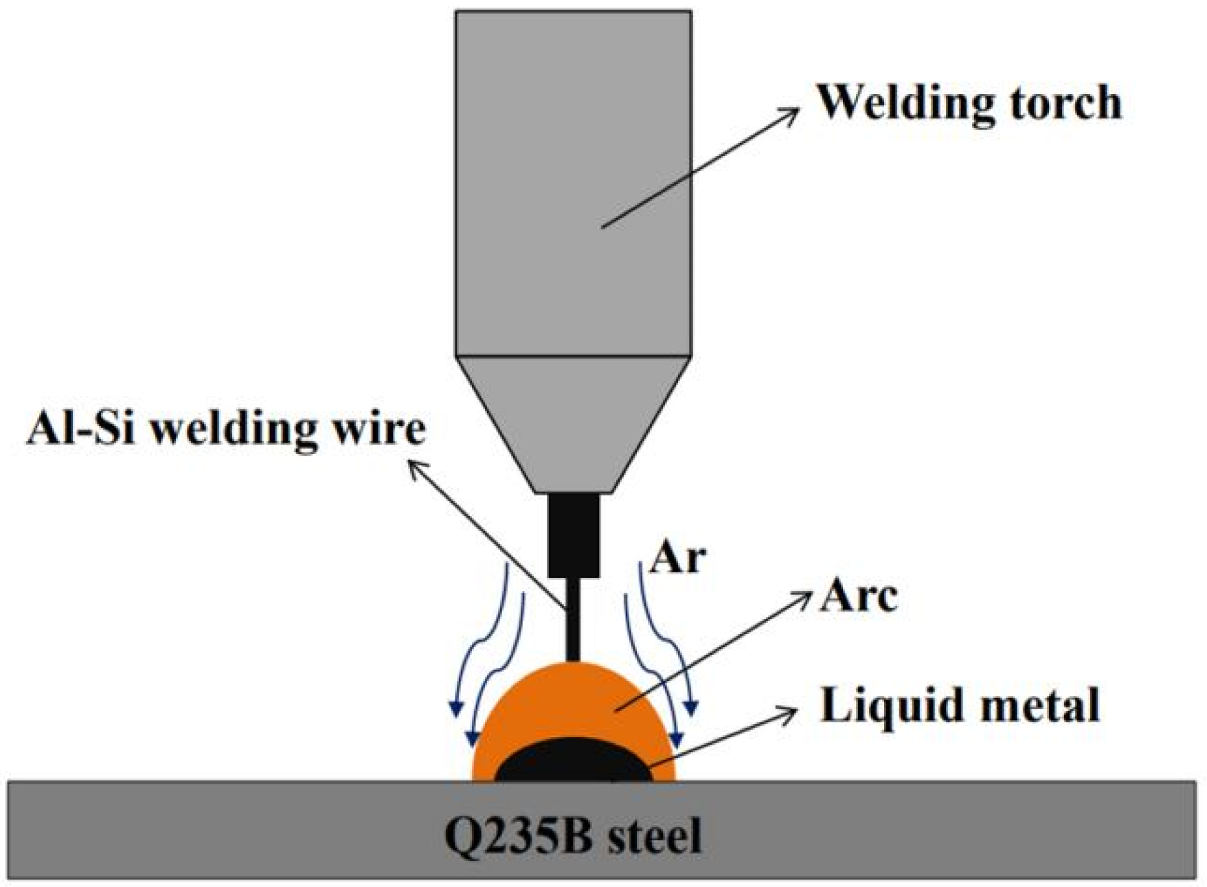
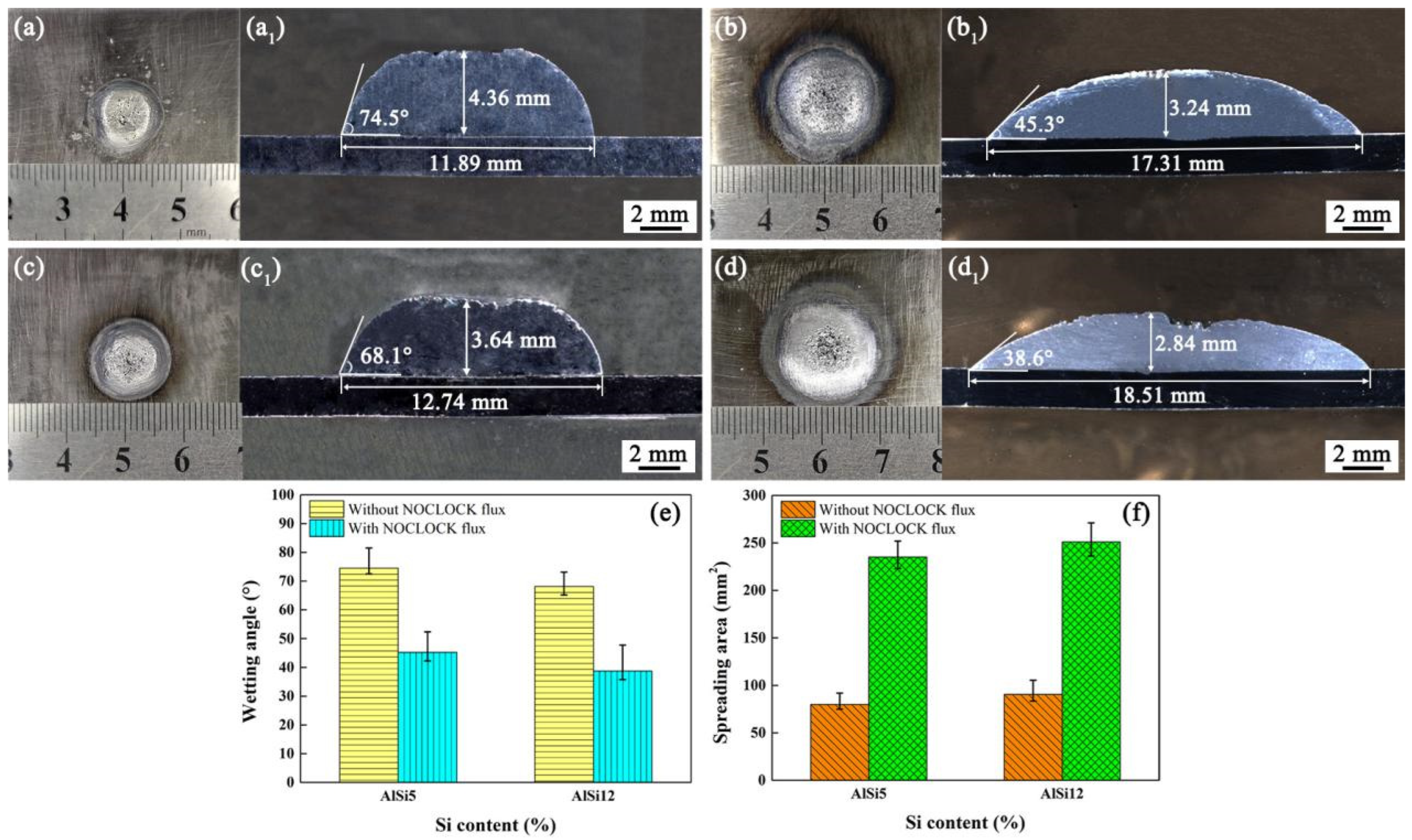
2.2. Wetting and Spreading Tests

Wetting and spreading experiments of the AlSi5 and AlSi12 flux-cored welding wires on the surface of the Q235B steel were carried out under the action of a CMT heat source, based on the GB/T 11364-2008 Wetting Test Method for Brazing Standard [27]. Its schematic diagram is shown in Figure 1. To prevent the Al–Si welding wire from being oxidized, a shielding gas was introduced first in the wetting and spreading test; the argon flow rate was 18 L/min. The distance from the welding torch nozzle to the workpiece was 18 mm, and the wire feeding speed was 5.5 m/min. The wetting angle and spreading area of the welding wire were measured by using Image Pro software (version 6.0), every sample in the group was repeated five times, and the final result used the average value of the measurements.

2.3. CMT Welding Brazing Tests

Butt joints of the 6082 aluminum alloy and Q235B steel were accomplished by CMT welding brazing by using AlSi5 and AlSi12 flux-cored welding wires as filler metals. Before welding, the surface was cleaned of base metals. When assembling, the Al alloy was not grooved while steel was prepared with a single V-shaped groove of 45°. The root gap between them was 0.1~0.5 mm, and a copper plate with a V-shaped groove was used to force the bottom forming of the weld. During the CMT welding brazing, the angle between the welding torch and the workpiece was 110°, and the distance from the workpiece to the welding wire tip was 2 mm. Argon gas with 99.99% purity was used to protect the welding process. Figure 2 illustrates the schematic diagram of the CMT welding brazing. Table 2 lists the process parameters of the CMT welding brazing.

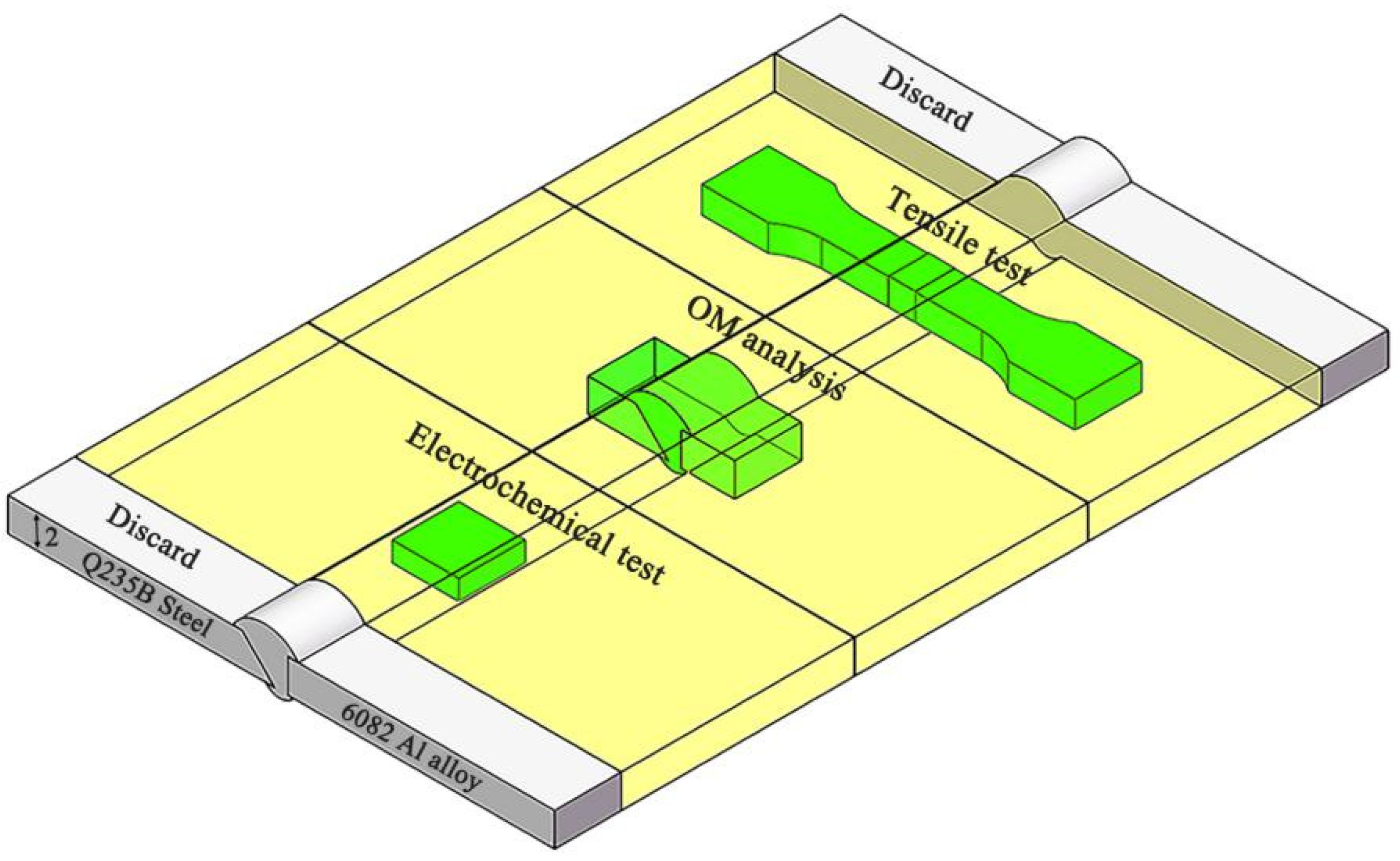
2.4. Microstructure Characterization and Properties Tests

After CMT welding brazing, samples used for the metallurgical, mechanical, and electrochemical corrosion tests were extracted and machined from each weld, as shown in Figure 3.
To analyze the weld appearance and microstructure composition of the joint together with exploring the formation behavior of IMCs at the interface, metallurgical samples were polished with a diamond suspension and then etched with Keller’s reagent for 10~15 s. We observed the macromorphology with a ZEISS optical microscope (OM). Also, we used a Scanning Electron Microscope (SEM) to analyze the microstructure and used Energy Dispersive Spectroscopy (EDS) to identify the element distribution. To confirm the phase composition of the Al alloy/steel joints, an X-ray diffractometer instrument (XRD) with a scanning angle (2θ) ranging from 10° to 90° and a scanning speed of 3 °/min was chosen.
The tensile experiments were conducted on four samples of each joint by a mechanical tester at a constant rate of 3 mm/min based on the GB/T 2651-2008 standard [28]. The result was the average value. The fracture morphology was observed by SEM. Electrochemical experiments were carried out by using the electrochemical workstation EGM283 with a three-electrode cell system in a 3.5 wt.% NaCl solution. We used the saturated calomel electrode (SCE) as a reference electrode, the platinum plate as an auxiliary electrode, and the Al alloy, steel, or Al alloy/steel joint as a working electrode. Specimens with a dimension of 10 mm × 10 mm × 2 mm were prepared. The potentiodynamic polarization curves were recorded with a scan rate of 2 mv/s and a scan range from −1 V to 1.5 V. To explore the corrosion resistance mechanism of the Al alloy/steel joints, we analyzed the composition of passivation films by X-ray photoelectron spectroscopy (XPS) with a monochromatic Al Ka radiation source. The composition of elements was determined according to the standard spectra of elements. The data were fitted by the commercial Avantage software (version 5.9).

3. Results and Discussion

3.1. Effect of Noclock Flux on the Wettability and Spreadability of Al–Si Welding Wires

Figure 4 shows the wetting and spreading morphologies, corresponding wetting angle, and spreading area of the AlSi5 and AlSi12 welding wires on the surface of low carbon steel under the action of a CMT heat source with the wire feeding speed of 5.0 m/min and an arc time of 4 s. As shown in Figure 4, the addition of Noclock flux obviously reduced the wetting angle of the Al–Si welding wire and increased its spreading area (see Figure 4a–d1). After adding Noclock flux to the welding wire, the wetting angle of the AlSi5 welding wire on the steel surface reduced from 74.5° to 45.3°and decreased by 39%, while the wetting angle of the AlSi12 welding wire on the steel surface decreased from 68.1° to 38.6° and reduced by 43% (see Figure 4e). Meanwhile, the spreading area of the AlSi5 welding wire increased by 195% and that of the AlSi12 welding wire increased by 176% (see Figure 4f).
In general, the elements Si and Al react easily with the O element to form SiO2 and Al2O3 oxidation with an Al–Si welding wire. These dense oxidation films hinder the flow and wetting of the molten Al alloy on the steel surface during the welding process and also prevent the mutual dissolution of the Al, Si, and Fe elements, which worsens the appearance of Al alloy/steel joints. The Noclock flux is mainly composed of KAlF4 and CsAlF4, with a small amount of NH4F and NH4AlF4. In this paper, after adding the Noclock flux to the Al–Si welding wire, the Noclock flux decomposes and then reacts with the SiO2 and Al2O3 oxide films at a high temperature of 530–570 °C. The reaction formulas are as follows [29,30]:
KAlF4 ⇌ KF + AlF3
CsAlF4 ⇌ CsF + AlF3
10KF + SiO2 + Al2O3 ≜ SiF4 + 2AlF3 + 5K2O
10CsF + SiO2 +Al2O3 ≜ SiF4 + 2AlF3 + 5Cs2O
In addition, NH4F and NH4AlF4 decompose and form HF. Furthermore, KAlF4 and CsAlF4 also react with H2O to generate HF.
NH4AlF4 ⇌ NH4F + AlF3
NH4F ≜ HF↑ + NH3
2KAlF4 + 3H2O ≜ 2KF + Al2O3 + 6HF↑
2CsAlF4 + 3H2O ≜ 2KF + Al2O3 + 6HF↑
HF can accelerate the removal of oxide films, and the reaction formulas are as follows:
4HF + SiO2 ≜ SiF4 + 2H2O
6HF + Al2O3 ≜ 2AlF3 + 3H2O
Obviously, HF plays a key role in improving the wettability of the Al–Si welding wire, which accelerates the removal of SiO2 and Al2O3 oxide films. Therefore, the wettability and spreadability of the Al–Si flux-cored welding wires are improved.

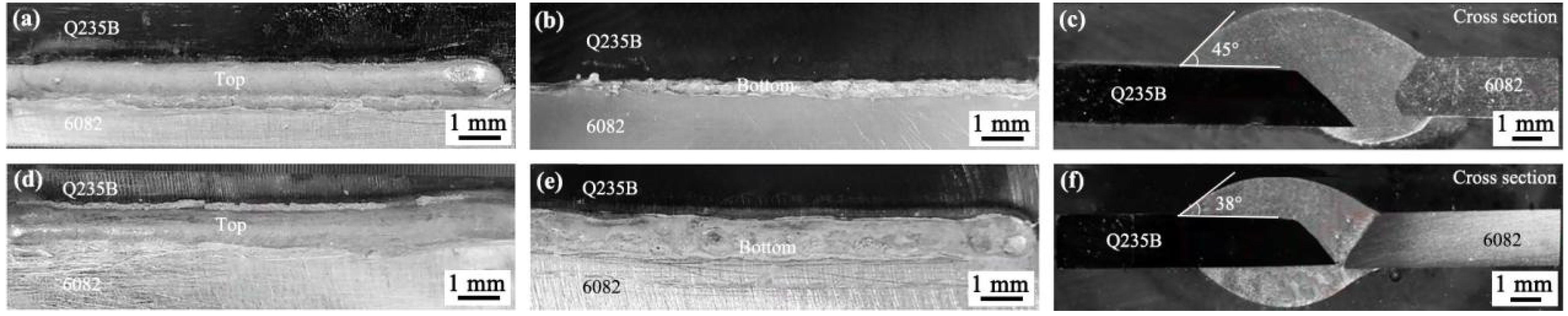
3.2. Macromorphology Analysis of Al Alloy/Steel CMT Welding-Brazing Joints with AlSi5 and AlSi12 Flux-Cored Welding Wire

Figure 5 shows the macromorphology of Al alloy and steel CMT welding-brazing joints with an AlSi5 and AlSi12 flux-cored welding wire, respectively. When using AlSi5 flux-cored welding wire as the filler metal, the top weld was relatively smooth with a high reinforcement, as shown in Figure 5a. However, the bottom weld was narrow and intermittent, not straight and smooth, as shown in Figure 5b. When using the AlSi12 flux-cored welding wire as the filler metal, the reinforcement of the top weld decreased and its width increased; compared to the weld with AlSi5 flux-cored welding wire, its bottom was straighter, more continuous, and smoother, as shown in Figure 5d,e, respectively. From Figure 5c,f, we can see that the wetting angles of the Al alloy/steel joints with AlSi5 and AlSi12 flux-cored welding wire were 45° and 38°, respectively. This indicated that the wettability of the AlSi12 flux-cored welding wire on the steel surface was better than that of the AlSi5 flux-cored welding wire, in particular, its back weld appearance was better.

3.3. Microstructure Analysis of Al Alloy/Steel CMT Welding-Brazing Joints with AlSi5 and AlSi12 Flux-Cored Welding Wire

Under the action of the CMT arc, the Al–Si welding wires and partial Al alloy started to melt but the steel did not melt. After wetting and spreading the molten Al alloy metal on the steel surface, an Al alloy/steel joint formed which was composed of the interface reaction zone and Al alloy fusion zone. SEM is used to observe the microstructure of Al alloy/steel joints with Al–Si flux-cored welding wires while EDS is chosen to analyze the characteristic points in the interface reaction zone and Al alloy fusion zone. Meanwhile, the SEM line scanning from the steel along the interface through the fusion zone to the Al alloy was performed to analyze the main element distribution in the Al alloy/steel joints. The phase composition of the Al alloy side and the steel side was determined by XRD after cutting off the Al alloy and steel joint along the interface.
Figure 6 shows the microstructure and the corresponding EDS line scanning results of the Al alloy/steel joints with AlSi5 and AlSi12 flux-cored welding wire. The interface layer of the joints included layer I near the steel side and layer II near the Al alloy fusion zone. The thickness of the IMCs layer in the joint was 3.27 μm and 3.01 μm from using the AlSi5 and AlSi12 flux-cored welding brazing as the filler metal, respectively. The EDS analysis of points A to J, in Figure 6a,c, was performed and the results are shown in Table 3. According to the Al–Si–Fe binary and ternary phase diagram together with previous research [31,32,33], it can be inferred from Table 3 that both point A and point E at the interface zone I near the steel side were θ-Fe (Al, Si)3, meanwhile, both point B and point F at the interface zone II near the Al alloy fusion zone were τ5-Al7.2Fe1.8Si. In addition, the dark gray zone (points C and G) in the Al alloy fusion zone was an α-Al solid solution, and the light gray needle-shaped zone (points D and J) were Al-Si eutectic phases. It was noted that the light gray bulk-like zone (point H) was the primary Si phase.
Figure 6b,d shows the EDS line scanning results of the joint marked in Figure 6a,c. As shown in the figure, the content of the Al element gradually decreased from the Al alloy side to the steel side and was enriched at the interface. Most content of the Si element was enriched in the Al alloy fusion zone and a few diffused into the interface reaction zone. The Fe element was mainly concentrated on the steel side, with a few distributed in the interface reaction zone and Al alloy fusion zone. This indicated that the Si element from the Al–Si welding wire diffused into the interface of the Al alloy/steel joint, and chemical metallurgical reactions occurred with the Fe element and Al element. Therefore, the interfacial compound changed from FeAl3 to Fe (Al, Si)3 near the steel side, which reduced the brittleness of the IMCs.
Figure 7 shows the XRD results on the steel side and the Al alloy side of the joint after cutting along the interface. From Figure 7, whether using AlSi5 or AlSi12 flux-cored welding wire, it can be seen that the phase at the Al alloy side was composed of an α-Al solid solution and τ5-Al7.2Fe1.8Si, while the phase at the steel side was θ-Fe (Al, Si)3. This result confirmed the phase composition of the Al alloy/steel joints.
From the above analysis, under the action of the CMT arc heat source, the Al–Si welding wire and partial Al alloy are seen to melt but the steel does not melt; the addition of Noclock flux improves the flowing and spreading of the molten Al alloy on the steel surface. The Fe element dissolves from the steel into the molten Al alloy, and the elements Al and Si diffuse from the liquid Al alloy into the steel. Through the metallurgical reactions among the Al, Fe, and Si elements, an Al–Fe–Si compound forms at the interface of the Al alloy/steel joint. Also, an α-Al solid solution and Al-Si eutectic phase form in the Al alloy fusion zone.
The Al–Fe–Si compound represents θ-Fe (Al, Si)3 and τ5-Al7.2Fe1.8Si in this paper. The formation sequence of these compounds depends on the Gibbs free energy ΔG. Generally, the ΔG value is negative, moreover, the smaller the ΔG value is, the easier it is for the compound to form. According to the literature [34,35,36], the Gibbs free energy ΔG of θ-Fe (Al, Si)3 and τ5-Al7.2Fe1.8Si are calculated by the following equation:
G Fe Al ,   Si 3   0 = 142770 + 50.8 T
G Al 7.2 Fe 1.8 Si   0 = 295355 + 94.59 T
where T represents the temperature; thus, both of their Gibbs free energy ΔG are less than zero and G Al 7.2 Fe 1.8 Si   0 <   G Fe Al ,   Si 3 0 in the process of CMT welding brazing. In the process of cooling, the τ5-Al7.2Fe1.8Si phase forms preferentially at the interface of the Al alloy/steel joints, as shown in Figure 8a. With the reaction continuing, the primary layer of the τ5-Al7.2Fe1.8Si phase is generated and grows. However, because the molten liquid Al alloy reacts intensely with the steel, the continuous erosion and dissolution of the liquid Al alloy to the interface layer occurs. At this time, some pores appear on the primary layer, so the Fe atom reacts with the τ5-Al7.2Fe1.8Si phase to form θ-Fe (Al, Si)3, as shown in Figure 8b.
Fe + τ 5 -Al 7.2 Fe 1.8 Si = θ -Fe Al ,   Si 3
After sufficient metallurgical reactions among elements Al, Fe, and Si, the interface reaction layer of the Al alloy/steel joint was composed of an θ-Fe (Al, Si)3 phase near the steel side and τ5-Al7.2Fe1.8Si phase near the Al alloy fusion zone, as shown in Figure 8c.

3.4. Tensile Properties Analysis of Al Alloy/Steel CMT Welding-Brazing Joints with AlSi5 and AlSi12 Flux-Cored Welding Wire

Figure 9 presents the tensile properties of Al alloy/steel CMT welding-brazing joints with Al–Si flux-cored welding wires. The average tensile strength of the joint with the AlSi5 flux-cored welding wire was 140.29 MPa, which was approximately 58.33% of the 6082 Al alloy (see Figure 9a). The average tensile strength of the joint with the AlSi12 flux-cored welding wire was 105.66 MPa and only 43.75% of the 6082 Al alloy, which was 20% lower than that of the joint with AlSi5 flux-cored welding wire (see Figure 9b).
Figure 10 shows the fracture locations and fracture morphologies of the Al alloy/steel CMT welding-brazing joints with an Al–Si flux-cored welding wire. As seen in Figure 10a,c, both of the joints fractured along the interface layer under the action of tensile stress. Their fractures were distributed with a large number of cleavage steps and appeared in river patterns, which displayed brittle failure, as shown in Figure 10b,d. Comparing Figure 10b with Figure 10d, the size of cleavage steps in the fracture with the AlSi12 flux-cored welding wire was smaller than that with the AlSi5 flux-cored welding wire. The former appeared to have tearing ridges; these suggested the toughness of the joint with the AlSi12 flux-cored welding wire was higher.
Whether using AlSi5 or AlSi12 flux-cored welding wire as the filler metal, both joints are composed of θ-Fe (Al, Si)3 and τ5-Al7.2Fe1.8Si in the interface reaction zone and α-Al solid solution and Al-Si eutectic phase in the Al alloy fusion zone. The difference between them is that the thickness of the IMCs of the joint with the AlSi5 flux-cored welding wire is higher than that with the AlSi12 flux-cored welding wire. Thus, the cleavage step size of the former fracture is larger, and the tensile strength of the former joint is better.

3.5. Corrosion Resistance Analysis of Al Alloy/Steel CMT Welding-Brazing Joints with AlSi5 and AlSi12 Flux-Cored Welding Wire

Figure 11 displays the electrochemical polarization curves of the base metals and Al alloy/steel joints with an Al–Si flux-cored welding wire. From Figure 11, during the corrosion process in a 3.5 wt.% NaCl solution, there was a passivation zone for the Al alloy, steel, and joints. This indicated that a stable oxide film formed on these metal surfaces to protect them from corrosion. In the initial stage, the corrosion rate of the metal is slow, the passivation film stays in a stable state, and the dissolution rate and regeneration rate of the metal are similar. With the potential and the corrosion current increasing, the dissolution rate of the passivation film increases. When the dissolution rate exceeds the regeneration rate, the passivation film starts to break down, and then the metal is corroded.
The data of self-corrosion potential and corrosion current density were obtained by fitting the polarization curve shown in Figure 11 through the Cview software (version 3.0), and the related results are listed in Table 4. The data of the self-corrosion potential represent the difficult degree of metal corrosion, and the higher the value is, the less likely the metal is to be corroded. The corrosion current density refers to the actual corrosion rate of a metal during the corrosion process, and the smaller the corrosion current density value is, the smaller the corrosion rate is [37]. Based on the value listed in Table 4, the corrosion resistance of the Al alloy was greater than that of the Al alloy/steel joint, and the corrosion resistance of steel was worse. The corrosion resistance of the joint with the AlSi12 flux-cored welding wire was slightly better than that with the AlSi5 flux-cored welding wire. This was attributed to the fact that the IMC thickness of the joint with the AlSi12 flux-cored welding wire was smaller than that with the AlSi5 flux-cored welding wire. Gu et al. [38] insisted that the increase in the IMC thickness accelerates the corrosion of joints.
To investigate the stability of the passivation films generated on the surface of the joint with AlSi5 and AlSi12 flux-cored welding wire, the samples were passivated for 1 h at 0.2 V SCE in a 3.5 wt.% NaCl solution. We performed the electrochemical impedance spectroscopy (EIS) measurements after the formation of the passivation film, and the EIS results of the joints with AlSi5 and AlSi12 flux-cored welding wire are presented in Figure 12. From Figure 12a, it can be seen that the two curves displayed the impedance behavior of passive film on the surface of the Al alloy/steel joint with the different Al–Si flux-cored welding wires. The passive films of joints had similar impedance characteristics, but the capacitive arc radius was different in the test frequency range. As reported in the literature [37], the polarization resistance value of the passive film was related to the capacitive arc diameter in the impedance measurement. The increase in the capacitive arc radius means the enhancement of the stability of the passive film and the corrosion resistance of joints. The capacitive arc radius of the passive film with the AlSi12 flux-cored welding wire was bigger than that with the AlSi5 flux-cored welding wire, and it meant the corrosion resistance of the joint with the AlSi12 flux-cored welding wire was optimal.
Figure 12b shows the Bode plots of passive films with different Al–Si flux-cored welding wires. Figure 12c presents the equivalent circuit which was chosen to fit the impedance data of the passive film by using Zview software(version 3.0). In this model, R1 is the solution resistance, R2 represents the charge transfer resistance of the passive film, R3 is the solute conduction impedance, CPE1 is the constant phase element, and C1 refers to the capacitance caused by solute conduction. Among them, the R2 value reflects the corrosion resistance of the joint. The larger the R2 value, the smaller the corresponding corrosion rate, and the better the corrosion resistance [39]. Table 5 lists the fitting parameters based on the equivalent circuit. As shown in Table 5, the R2 value of the joint with AlSi12 flux-cored welding wire was higher than that with AlSi5 flux-cored welding wire, which suggests that the compactness and stability of the former passive film was better.
Figure 13 shows the XPS spectra results of the Al alloy/steel joint with the AlSi12 flux-cored welding wire. It was observed that five obvious spectrum peaks including Fe, Al, Si, O, and C coexisted in the XPS total spectra, as shown in Figure 13a. According to the peak intensity of the elements, elements Fe, Al, Si, and O dominated the components of the passive film. The high-intensity peak of the O element indicates the presence of a large amount of metal oxides in the passivation film. The C element was used to adjust other peaks, so the C element signal may be an impurity introduced in the preparation process. Figure 13b displays the iron profile with four peaks: Fe3+ 2p1/2 (725.28 eV), Fe2+ 2p1/2 (723.58 eV), Fe3+ 2p3/2 (713.78 eV), and Fe2+2p3/2, which suggests that Fe2+and Fe3+ are the main types of iron oxides in the passive film. Figure 13c presents the aluminum profile showing one characteristic peak of Al3+ 2p (74.38 eV). The Al element reacts easily with the O element to form Al2O3, which can increase the corrosion resistance of the Al alloy/steel joint. Figure 13d shows the silicon profile forms three peaks: Si4+ 2p (102.28 eV), SiOx 2p (101.38 eV), and Si2p (99.08 eV). This indicated that silicon oxides formed in the passive film. Thus, the various oxides formed in the passivation film are the main reason for the corrosion resistance of the joint.

4. Conclusions

An Al alloy and low carbon steel were joined by using CMT welding brazing with AlSi5 and AlSi12 flux-cored (Noclock flux) welding wires as the filler metals. The effect of Noclock flux on the wettability and spreadability of the Al–Si welding wires to the steel surface was discussed. The macromorphology, microstructure, and properties of the Al alloy/steel joints were analyzed. The main conclusions were drawn as follows:
(1)
The addition of Noclock flux improved the wettability and spreadability of the Al–Si welding wires on the low-carbon steel surface, resulting in the good appearance of the Al alloy/steel CMT welding joints. Compared to the AlSi5 flux-cored welding wire, the AlSi12 flux-cored welding wire had better wettability and spreadability.
(2)
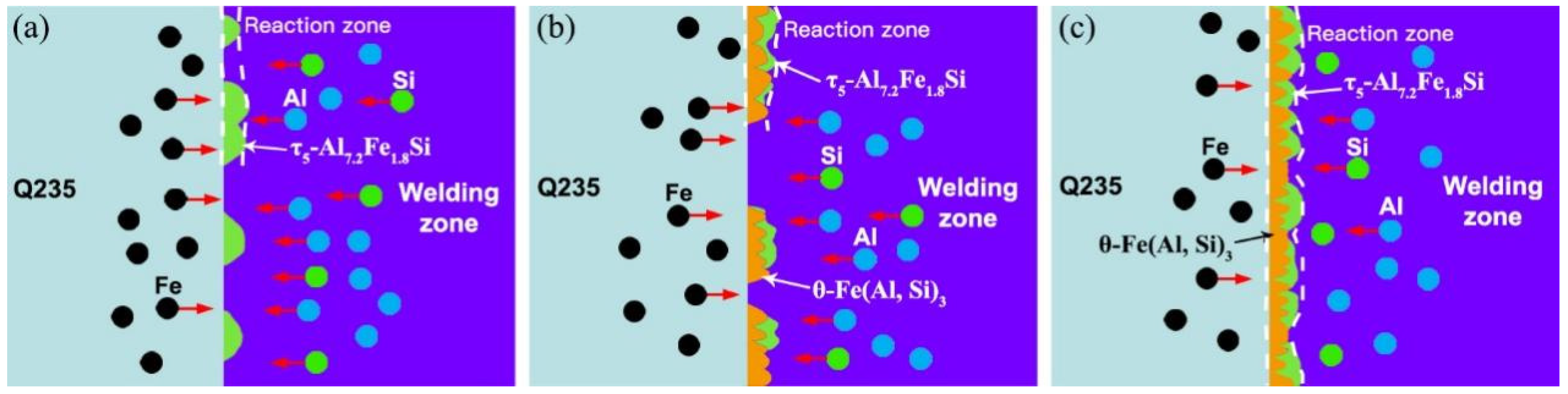
When using AlSi5 and AlSi12 flux-cored welding wires, the Al alloy/steel CMT welding-brazing joints were both composed of θ-Fe (Al, Si)3 and τ5-Al7.2Fe1.8Si formed at the interface reaction zone as well as an α-Al solid solution and Al-Si eutectic phase generated in the Al alloy fusion zone. Compared with the two joints, the IMC thickness of the joint with the AlSi12 flux-cored welding wire was thinner.
(3)
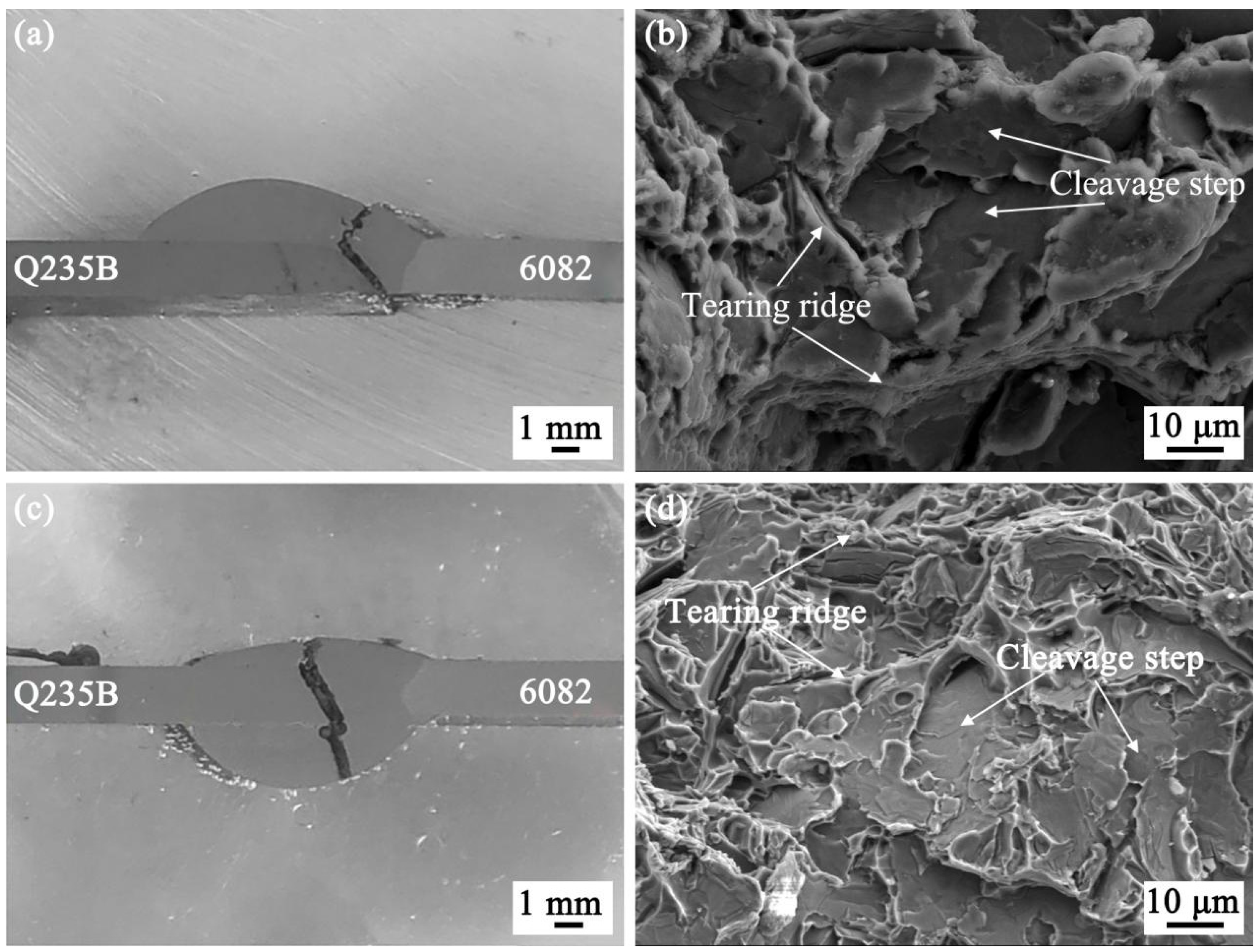
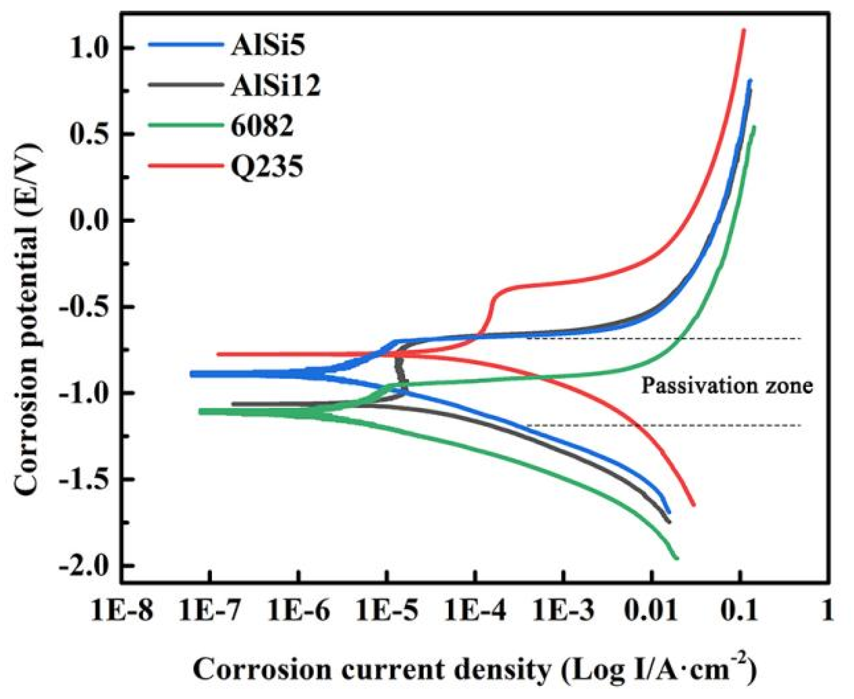
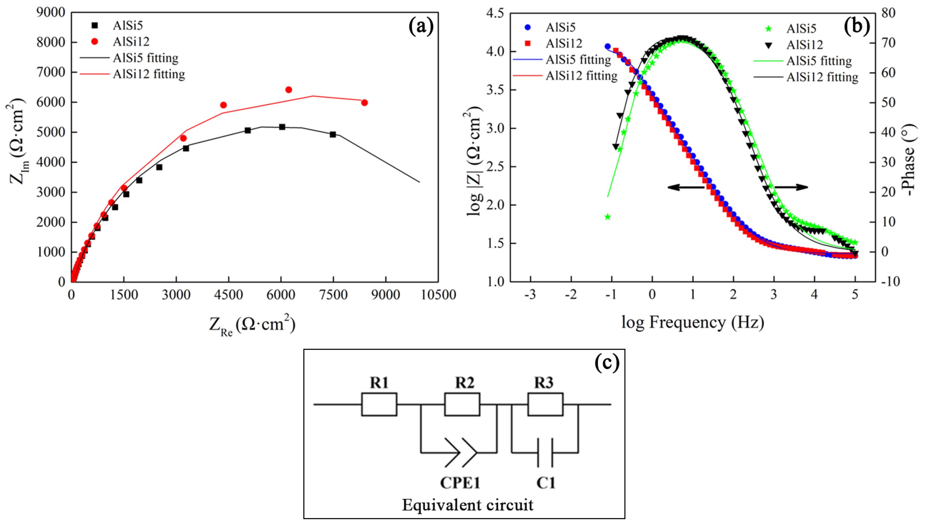
The tensile strength of the Al alloy/steel joint with the AlSi12 flux-cored welding wire was slightly lower than that of the joint with the AlSi5 flux-cored welding wire, and its corrosion resistance was better. This was attributed to the thinner IMC thickness at the interface of the joint.
(4)
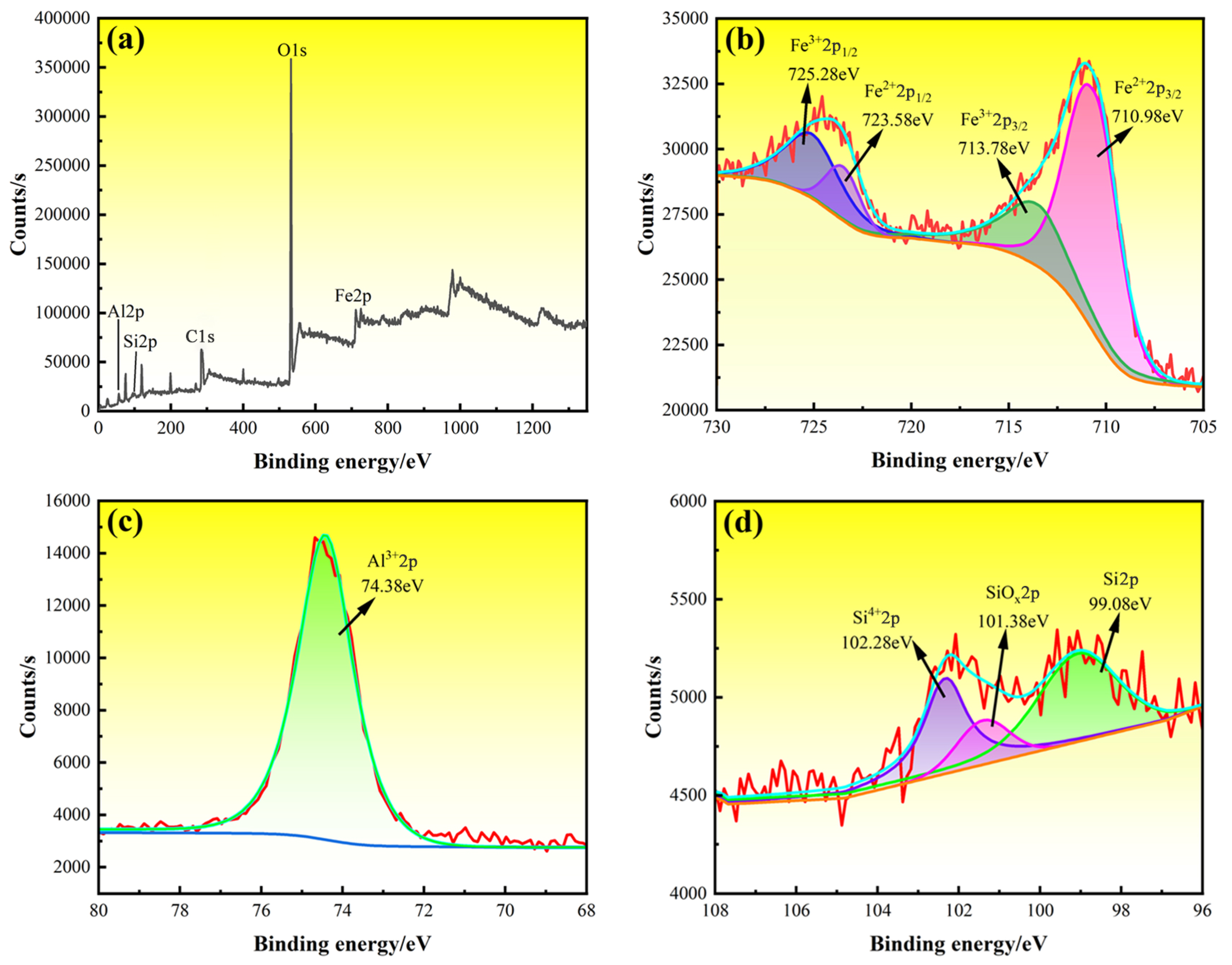
The reason for the good corrosion resistance of the Al alloy/steel joint with the AlSi12 flux-cored welding wire was due to the presence of a large amount of Fe, Al, and Si oxides in the passivation film.

Author Contributions

Conceptualization, H.L., J.P. and M.W.; methodology, H.L. and J.R.; validation, H.L., M.W., and J.P.; investigation, Y.S.; resources, Y.S.; date curation, C.Z.; formal analysis, C.Z.; writing—original draft preparation, H.L., M.W., and J.P.; writing—review and editing, W.L. and M.W.; writing—manuscript finalization, J.P., H.L., and M.W. supervision, M.W. and W.L.; project administration, W.L. and M.W.; funding acquisition, Y.S. and W.L. All authors have read and agreed to the published version of the manuscript.

Funding

This research was supported by Jiangsu University (High-tech Ship) Cooperative Innovation Centre and Institute of Marine Equipment (No. HZ2018008), Jiangsu Province Undergraduate Innovation Project and Jiangsu Key Laboratory Project of Green Ship Technology (No. 2019Z02), and Shanghai Polytechnic University (No. C80ZK230037).

Institutional Review Board Statement

Not applicable.

Informed Consent Statement

Not applicable.

Data Availability Statement

Not applicable.

Conflicts of Interest

The authors declare no conflict of interest. The funder had no role in the design of the study; in the collection, analysis, or interpretation of data; in the writing of the manuscript; or in the decision to publish the results.

References

  1. Jeong, S.; Lee, Y.; Park, G.; Kim, B.; Moon, J.; Park, S.-J.; Lee, C. Phase transformation and the mechanical characteristics of heat-affected zones in austenitic Fe–Mn–Al–Cr–C lightweight steel during post-weld heat treatment. Mater. Charact. 2021, 177, 111150. [Google Scholar] [CrossRef]
  2. Harwarth, M.; Chen, G.; Rahimi, R.; Biermann, H.; Zargaran, A.; Duffy, M.; Zupan, M.; Mola, J. Aluminum-alloyed lightweight stainless steels strengthened by B2-(Ni, Fe)Al precipitates. Mater. Des. 2021, 206, 109813. [Google Scholar] [CrossRef]
  3. Adamiak, M.; Wyględacz, B.; Czupryński, A.; Górka, J. A study of susceptibility and evaluation of causes of cracks formation in braze-weld filler metal in lap joints aluminum-carbon steel made with use of CMT method and high power diode laser. Arch. Metall. Mater. 2017, 62, 2113–2123. [Google Scholar] [CrossRef]
  4. Zhang, C.; Wu, M.; Pu, J.; Rao, J.; Long, W.; Shen, Y. Effect of Ni coating on microstructure and property of Al alloy/steel CMT welding-brazing joints. Coatings 2023, 13, 418. [Google Scholar] [CrossRef]
  5. Bergh, T.; Arbo, S.M.; Hagen, A.B.; Blindheim, J.; Friis, J.; Khalid, M.Z.; Ringdalen, I.G.; Holmestad, R.; Westermann, I.; Vullum, P.E. On intermetallic phases formed during interdiffusion between aluminium alloys and stainless steel. Intermetallics 2022, 142, 107443. [Google Scholar] [CrossRef]
  6. Dang, Z.; Qin, G.; Wang, J. Bonding mechanism and fracture behavior of inertia friction welded joint of 2219 aluminum alloy to 304 stainless steel. Mater. Sci. Eng. A 2023, 866, 144641. [Google Scholar] [CrossRef]
  7. Zhang, X.; Gao, K.; Wang, Z.; Hu, X.; Liu, H.; Nie, Z. Effect of intermetallic compounds on interfacial bonding of Al/Fe composites. Mater. Lett. 2023, 333, 133597. [Google Scholar] [CrossRef]
  8. Wloka, J.; Laukant, H.; Glatzel, U.; Virtanen, S. Corrosion properties of laser beam joints of aluminium with zinc-coated steel. Corros. Sci. 2007, 49, 4243–4258. [Google Scholar] [CrossRef]
  9. Xue, Z.; Wang, X.; Xu, C.; Chen, Z.; Feng, X.; Zhou, Q.; Liu, J.; Li, L. Equivalent characterization of pre-strained material properties and mechanical behavior prediction of steel/aluminum self-piercing riveted joints. Thin. Wall. Struct. 2023, 182, 110243. [Google Scholar] [CrossRef]
  10. Chen, W.; Deng, H.; Dong, S.; Zhu, Z. Numerical modelling of lockbolted lap connections for aluminium alloy plates. Thin. Wall. Struct. 2018, 130, 1–11. [Google Scholar] [CrossRef]
  11. Sundaraselvan, S.; Senthilkumar, N.; Balamurugan, T.; Kaviarasu, C.; Sathishkumar, G.B.; Rajesh, M. Optimization of friction welding process parameters for joining Al6082 and mild steel using RSM. Mater. Today Proc. 2023, 74, 91–96. [Google Scholar] [CrossRef]
  12. Sun, H.; Yu, G.; Chen, S.; Huang, J.; Yang, J. Effect of ZnAl filler metals on the characteristics of the joint made by the high-frequency induction brazing of 304 stainless steel and 6A02 aluminum. J. Manuf. Process. 2021, 68, 961–972. [Google Scholar] [CrossRef]
  13. Zhang, C.; Wu, M.; Pu, J.; Shan, Q.; Sun, Y.; Wang, S.Q.; Hermann, S.K.U.G. Effect of Cu Coating on microstructure and properties of Al/steel welding-brazing joints obtained by cold metal transfer (CMT). Coatings 2022, 12, 1123. [Google Scholar] [CrossRef]
  14. Li, J.; Shi, Y.; Huang, J.K. Corrosion properties of aluminum-steel dissimilar metals MIG welding-brazing joint. Hot Work. Technol. 2018, 47, 214–217+222. [Google Scholar]
  15. Qin, G.; Ji, Y.; Ma, H.; Ao, Z. Effect of modified flux on MIG arc brazing-fusion welding of aluminum alloy to steel butt joint. J. Mater. Process. Technol. 2017, 245, 115–121. [Google Scholar] [CrossRef]
  16. Ye, Z.; Huang, J.; Gao, W.; Zhang, Y.; Cheng, Z.; Chen, S.; Yang, J. Microstructure and mechanical properties of 5052 aluminum alloy/mild steel butt joint achieved by MIG-TIG double-sided arc welding-brazing. Mater. Des. 2017, 123, 69–79. [Google Scholar] [CrossRef]
  17. Mohammadpour, M.; Yazdian, N.; Wang, H.-P.; Carlson, B.; Kovacevic, R. Effect of filler wire composition on performance of Al/Galvanized steel joints by twin spot laser welding-brazing method. J. Manuf. Process. 2018, 31, 20–34. [Google Scholar] [CrossRef]
  18. Wallerstein, D.; Solla, E.L.; Lusquiños, F.; Comesaña, R.; del Val, J.; Riveiro, A.; Pou, J. Advanced characterization of intermetallic compounds in dissimilar aluminum-steel joints obtained by laser welding-brazing with AlSi filler metals. Mater. Charact. 2021, 179, 111345. [Google Scholar] [CrossRef]
  19. Yuan, R.; Deng, S.; Cui, H.; Chen, Y.; Lu, F. Interface characterization and mechanical properties of dual beam laser welding-brazing Al/steel dissimilar metals. J. Manuf. Process. 2019, 40, 37–45. [Google Scholar] [CrossRef]
  20. Peng, M.; Liu, H.; Liang, Y.; Xu, W.; Zhao, Y.; Chen, S.; Weng, J.; Yang, J. CMT welding-brazing of Al/steel dissimilar materials using cycle-step mode. J. Mater. Res. Technol. 2022, 18, 1267–1280. [Google Scholar] [CrossRef]
  21. Yu, G.; Chen, S.; Zhao, Z.; Wen, Z.; Huang, J.; Yang, J.; Chen, S. Comparative study of laser swelding-brazing of aluminum alloy to galvanized steel butted joints using five different filler wires. Opt. Laser Technol. 2022, 147, 107618. [Google Scholar] [CrossRef]
  22. Ma, Y.; Dong, H.; Li, P.; Yang, J.; Wu, B.; Hao, X.; Xia, Y.; Qi, G. A novel corrosion transformation process in aluminum alloy/galvanized steel welded joint. Corros. Sci. 2022, 194, 109936. [Google Scholar] [CrossRef]
  23. Matsuda, T.; Ogaki, T.; Hayashi, K.; Iwamoto, C.; Nozawa, T.; Ohata, M.; Hirose, A. Fracture dominant in friction stir spot welded joint between 6061 aluminum alloy and galvannealed steel based on microscale tensile testing. Mater. Des. 2022, 213, 110344. [Google Scholar] [CrossRef]
  24. Chen, S.H.; Li, S.Q.; Li, Y.; Huang, J.H.; Chen, S.J.; Yang, J. Butt welding-brazing of steel to aluminum by hybrid laser-CMT. J. Mater. Process. Technol. 2019, 272, 163–169. [Google Scholar] [CrossRef]
  25. Mei, S.W.; Gao, M.; Yan, J.; Zhang, C.; Li, G.; Zeng, X.Y. Interface properties and thermodynamic analysis of laser–arc hybrid welded Al/steel joint. Sci. Technol. Weld. Join. 2013, 18, 293–300. [Google Scholar] [CrossRef]
  26. Singh, J.; Arora, K.S.; Shukla, D.K. Lap weld-brazing of aluminum to steel using novel cold metal transfer process. J. Mater. Process. Technol. 2020, 283, 116728. [Google Scholar] [CrossRef]
  27. GB/T 11364-2008; Test Method of Wettability for Brazing Filler Metals. Ministry of Chemical Industry of the People Republic of China: Beijing, China, 2008.
  28. GB/T 2651-2008; Tensile Test Method on Welded Joints. Ministry of Chemical Industry of the People Republic of China: Beijing, China, 2008.
  29. Zhang, J.; Xue, S.; Xue, P.; Yang, J.; Lv, Z. Effect of Ga2O3 on the wettability and spreadability of CsF-RbF-AlF3 Flux/Zn-Al filler metal on aluminum and steel. Rare Metal Mater. Eng. 2017, 46, 1900–1904. [Google Scholar]
  30. Zhu, H.; Xue, S.B.; Sheng, Z. Mechanism of CsF-AlF3 and KF-AlF3 fluxes reacting with oxide films of 6063 aluminum alloy. Trans. China Weld. Inst. 2009, 30, 13–16+20+113. [Google Scholar]
  31. Wang, T.; Chen, C.; Ma, J.; Wei, S.; Xiong, M.; Mao, F.; Zhang, P.; Zhang, G. Influence of Si on the intermetallic compound formation in the hot-dipped aluminide medium carbon steel. Mater. Charact. 2023, 197, 112700. [Google Scholar] [CrossRef]
  32. Marker, M.C.J.; Skolyszewska-Kühberger, B.; Effenberger, H.S.; Schmetterer, C.; Richter, K.W. Phase equilibria and structural investigations in the system Al–Fe–Si. Intermetallics 2011, 19, 1919–1929. [Google Scholar] [CrossRef]
  33. Deshmukh, A.A.; Khond, A.A.; Palikundwar, U.A. Prediction of glass forming compositions in Al-Fe-Si alloy system by thermodynamic approach. J. Non-Cryst. Solids 2017, 477, 50–57. [Google Scholar] [CrossRef]
  34. Du, Y.; Schuster, J.C.; Liu, Z.-K.; Hu, R.; Nash, P.; Sun, W.; Zhang, W.; Wang, J.; Zhang, L.; Tang, C.; et al. A thermodynamic description of the Al–Fe–Si system over the whole composition and temperature ranges via a hybrid approach of CALPHAD and key experiments. Intermetallics 2008, 16, 554–570. [Google Scholar] [CrossRef]
  35. Guo, Y.; Wang, Y.; Chen, H.; Xu, H.; Hu, M.; Ji, Z. Anisotropic elasticity, electronic structure and thermodynamic properties of Al-Fe-Si intermetallic compounds from first principles calculations. Solid State Commun. 2019, 298, 113643. [Google Scholar] [CrossRef]
  36. Yang, J.; Hu, A.; Li, Y.; Zhang, P.; Chandra Saha, D.; Yu, Z. Heat input, intermetallic compounds and mechanical properties of Al/steel cold metal transfer joints. J. Mater. Process. Technol. 2019, 272, 40–46. [Google Scholar] [CrossRef]
  37. Kang, D.H.; Lee, H.W. Study of the correlation between pitting corrosion and the component ratio of the dual phase in duplex stainless steel welds. Corros. Sci. 2013, 74, 396–407. [Google Scholar] [CrossRef]
  38. Gu, Y.F.; Li, J.; Shi, Y.; Huang, J.K.; Fan, D. Corrosion property of arc welding brazed joint between aluminum and steel. Chin. J. Nonferr. Met. 2016, 26, 758–765. [Google Scholar]
  39. Birbilis, N.; Buchheit, R.G. Electrochemical characteristics of intermetallic phases in aluminum alloys: An experimental survey and discussion. J. Electrochem. Soc. 2005, 152, B140. [Google Scholar] [CrossRef]
Figure 1. Schematic diagram of the wetting and spreading of the Al–Si flux-cored welding wire.
Coatings 13 01590 g001
Figure 2. Schematic diagram of the CMT welding brazing process.
Coatings 13 01590 g002
Figure 3. The locations of all test samples.
Coatings 13 01590 g003
Figure 4. Wetting and spreading morphologies, corresponding to the wetting angle and spreading area of the AlSi5 and AlSi12 welding wires on the steel surface: (a,a1) AlSi5 welding wire; (b,b1) AlSi5 flux-cored welding wire; (c,c1) AlSi12 welding wire; (d,d1) AlSi12 flux-cored welding wire; (e) wetting angle; and (f) spreading area.
Coatings 13 01590 g004
Figure 5. Macromorphology of Al alloy/steel CMT welding-brazing joints with Al–Si flux-cored welding wires: (ac) AlSi5 flux-cored welding wire and (df) AlSi12 flux-cored welding wire.
Coatings 13 01590 g005
Figure 6. The microstructure and EDS line scanning results of the Al alloy/steel CMT welding-brazing joints with Al–Si cored-flux welding wires: (a,b) AlSi5 flux-cored welding wire and (c,d) AlSi12 flux-cored welding wire.
Coatings 13 01590 g006
Figure 7. XRD results of the Al alloy/steel CMT welding-brazing joint with AlSi2 flux-cored welding wire: (a) steel side and (b) Al alloy side.
Coatings 13 01590 g007
Figure 8. Formation behavior on IMC layer of Al alloy/steel CMT welding-brazing joints: (a) Stage I; (b) stage II; and (c) stage III.
Coatings 13 01590 g008
Figure 9. Tensile properties of Al alloy/steel CMT welding-brazing joints: (a) AlSi5 flux-cored welding wire and (b) AlSi12 flux-cored welding wire.
Coatings 13 01590 g009
Figure 10. Fracture location and fracture morphology of Al alloy/steel CMT welding-brazing joints: (a,b) AlSi5 flux-cored welding wire and (c,d) AlSi12 flux-cored welding wire.
Coatings 13 01590 g010
Figure 11. Polarization curves of base metals and Al alloy/steel joints with Al–Si flux-cored welding wires.
Coatings 13 01590 g011
Figure 12. Nyquist plots and EIS equivalent circuit diagram of Al alloy/steel welding-brazing joints: (a) Nyquist plots; (b) Bode plots; and (c) equivalent circuit.
Coatings 13 01590 g012
Figure 13. XPS spectra of the passive film on the surface of the Al alloy/steel joint with AlSi12 flux-cored welding wire: (a) total spectrum; (b) Fe2p; (c) Al2p; and (d) Si2p.
Coatings 13 01590 g013
Table 1. Chemical composition and properties of base metals and Al–Si flux-cored wires.
MaterialsChemical CompositionProperties
AlSiFeMnMgCuZnTiCrCMelting Point/°CHeat Conductivity W/(m·K)Tensile Strength/MPa
6082Bal.1.00.50.60.90.10.20.15649125240
Q2350.2Bal.0.20.70.2150077.5375
AlSi5Bal.5.70.20.050.00480.0070.0020.2<0.01
AlSi12Bal.12.20.20.070.00020.00570.00480.2<0.01
Noclock
Flux
KAlF4CsAlF4
973
Table 2. CMT welding-brazing parameters.
ParametersValue
Shielding gas flow, L/min18
Wire feeding speed, m/min5.5
Welding speed, mm/min400
Welding voltage, V12.0
Welding current, A105
Table 3. The EDS results and possible phases of corresponding test points in Figure 6.
Test PointsElement Ration (at. %)Possible Phases
AlSiFe
A71.310.418.3θ-Fe (Al, Si)3
B76.55.018.5τ5-Al7.2Fe1.8Si
C97.230.921.85α-Al solid solution
D80.319.50.2Al-Si eutectic
E70.115.614.3θ-Fe (Al, Si)3
F78.45.316.3τ5-Al7.2Fe1.8Si
G98.010.851.14α-Al solid solution
H1.8198.19primary Si phase
J85.613.11.3Al-Si eutectic
Table 4. Self-corrosion potential and corrosion current density obtained from Figure 11.
MaterialsSelf-Corrosion Potential/VCorrosion Current Density/(A·cm−2)
Al alloy−0.5923.35 × 10−6
Steel−1.1905.20 × 10−5
Joint with AlSi5−0.7134.95 × 10−6
Joint with AlSi12−0.7024.82 × 10−6
Table 5. Fitting parameters of the EIS results obtained from a proposed equivalent model shown in Figure 12c.
R1 (Ω/cm2)CPE1-T (Scm−2s−1)CPE1-P (Scm−2s−1)R2 (Ω/cm2)C1 (μFcm−1)R3 (Ω/cm2)
AlSi517.391.87 × 10−40.7215407.23 × 10−4818.7
AlSi1215.563.09 × 10−40.7025512.29 × 10−4725.5
Disclaimer/Publisher’s Note: The statements, opinions and data contained in all publications are solely those of the individual author(s) and contributor(s) and not of MDPI and/or the editor(s). MDPI and/or the editor(s) disclaim responsibility for any injury to people or property resulting from any ideas, methods, instructions or products referred to in the content.

