Article

The Effects of Ultrasonic Impact Modification on the Surface Quality of 20CrNiMo Carburized Steel

College of Marine Equipment and Mechanical Engineering, Jimei University, Xiamen 361000, China
*
Author to whom correspondence should be addressed.
Coatings 2023, 13(9), 1594; https://doi.org/10.3390/coatings13091594
Submission received: 6 July 2023 / Revised: 5 September 2023 / Accepted: 8 September 2023 / Published: 12 September 2023

Abstract

:
Ultra-high residual compressive stress can be introduced via the ultrasonic impact on the basis of transformation hardening, and further enhance the overall performance of 20CrNiMo carburized steel. In order to achieve the best surface quality of 20CrNiMo carburized steel, ultrasonic impact modification testing with varying static loads (900 N, 1200 N, and 1500 N) and rounds (1, 3, and 6) was conducted. By characterizing microhardness, microstructure, the surface roughness and residual compressive stress, the influence of ultrasonic impact modification parameters on its surface quality were analyzed. The experimental results indicated that the static loads and rounds of ultrasonic impact modification had a significant impact on the surface quality. The best surface quality could be obtained after six rounds of ultrasonic impact modification under a static load of 1200 N. In addition, the surface roughness decreased from 0.40 μm to 0.04 μm, the surface microhardness increased from 679 HV0.1 to 1086 HV0.1, and the maximum residual compressive stress of 1195.36 MPa was formed. Furthermore, the surface quality would deteriorate when the static load and ultrasonic impact rounds were increased.

1. Introduction

Most fatigue cracks in crucial components are generated from the surface quality. Relevant studies demonstrate that there is a strong relationship between the surface quality of crucial components and their fatigue strength. The high residual compressive stress, high hardness, and low roughness of the surface layer can suppress crack initiation and expansion to some extent [1,2]. 20CrNiMo is a common low-carbon alloy steel with good toughness, high hardenability, a low tendency to cold crack, no temper brittleness, and excellent cutting properties. It is extensively utilized in the manufacturing of crucial components [3].
Low-carbon steel usually needs carburization treatment to increase the surface hardness due to the relatively low carrying capacity. In addition, the construction with a hard surface layer and a tough core can be formed via carburization treatment to absorb impact loads better, which can improve the fatigue service performance of crucial components [4,5]. However, the enhancement of fatigue performance was relatively limited, and more work can be carried out to make it better. Strain-hardening technologies, such as ultrasonic impact and laser impact, were a type of modification method for increasing the crucial components’ fatigue life. Mechanical loads are forced on the surface to produce strong plastic deformation [6], making the local stress exceed the material’s yield limit, causing grain refinement and surface hardness improvement [7], and forming high amplitude residual compressive stress [8]. In contrast, ultrasonic impact has better controllability and applicability and higher processing efficiency. It can generate high-amplitude residual compressive stress while achieving very low surface roughness, making it widely used for surface modification of crucial components [9].
Currently, metal materials without transformation hardening with a soft matrix structure and low strength are the focus of research on ultrasonic impact [10]. Sun et al. [11] carried out the ultrasonic impact treatment on 7050 aluminum alloy and obtained a residual compressive stress of 280.8 MPa. The microhardness increased from 110 HV0.1 to 155 HV0.1. Wang et al. [12] made the ultrasonic impact treatment on 18CrNiMo7-6 alloy steel after tempering in order for its surface hardness increased from 426 HV0.1 to 484 HV0.1 and introduced a residual compressive stress of 343 MPa on its surface. We can observe that the material strength limits the application effect of ultrasonic impact modification to a great extent. In the research, Zhang et al. [13] discovered that a microhardness of 905 HV0.2 and a surface residual compressive stress of 527 MPa could be obtained after the ultrasonic impact of 17Cr2Ni2MoVNb carburized steel under a static load of 1000 N. As the surface quality improved, the contact fatigue life increased by 2.6 times. Liu et al. [14] found that the surface quality was improved most after six rounds of repeated ultrasonic impact on 18CrNiMo carburized steel. Its hardness increased to 876 HV0.1 and the maximum residual compressive stress reached 790 MPa. It is shown that the surface quality of metal materials is closely related to the static load and the rounds of ultrasonic impacts. It is generally believed to effectively suppress the initiation and expansion of microscopic cracks by decreasing the surface roughness, increasing the surface hardness and introducing high-amplitude residual compressive stress [15,16,17]. Presently, there are few studies on the effects of static load and the impact round on surface quality of carburized steel. Additionally, the surface microhardness, surface roughness, and residual compressive stress of components are not independent with the service performance. Finding the appropriate range is of great practical value for guiding the design and research work of ultrasonic impact technology. Combined with the experiments, the process parameters were found to gain the best surface quality by calibrating indicators.

2. Principles of Ultrasonic Impact Modification

Ultrasonic impact is a modification method that involves converting the sinusoidal signal generated by the ultrasonic generator into mechanical vibration through a transducer. In addition, the vibration will be amplified by the ultrasonic horn to drive the impact head, and finally a high-frequency impact is applied to the workpiece. The principle is as shown in Figure 1. Driven by the static load, load and the ultrasonic load, the ultrasonic impact head closely contacts with the workpiece and causes high-frequency collisions. The material is forced to undergo severe plastic deformation. Through stable feeding, an orderly overlap is formed between strengthened areas, surface roughness is reduced, and “peak shaving and valley filling” is realized. In this process, under the combined action of elasticoplastic deformation and the elastic restoring force of the internal material, a stress field with a specific distribution rule is formed. Furthermore, the hardness and fatigue performance of equipment are enhanced to a certain extent.
As depicted in Figure 2, low-carbon steel can obtain acicular Martensite with high hardness and high strength on its surface layer and lath Martensite on its core after carburizing, quenching, and tempering. As a result, it will form a structure with a hard surface layer and a tough core. Therefore, in the process of ultrasonic impact modification, smaller effective grains are formed in the surface layer, and very high deformation resistance and ultra-high residual compressive stresses are generated simultaneously. Finally, a gradient structure that gradually transitions from the ultrafine effective grains on the surface to the original grains in the core is obtained. The load can be transmitted to the structure more smoothly and effectively. On the other hand, the appropriate ultrasonic impact technology can enhance the surface microtopography of the structure to a great extent, eliminating a large number of microdefects and stress concentrations on the surface of the component. It can also avoid inducing crack initiation and fatigue failure under cyclic loading. Therefore, the exploration of a reasonable ultrasonic impact modification is of great significance for improving the fatigue service performance of 20CrNiMo carburized steel.

3. Experimental Design of Ultrasonic Impact Modification

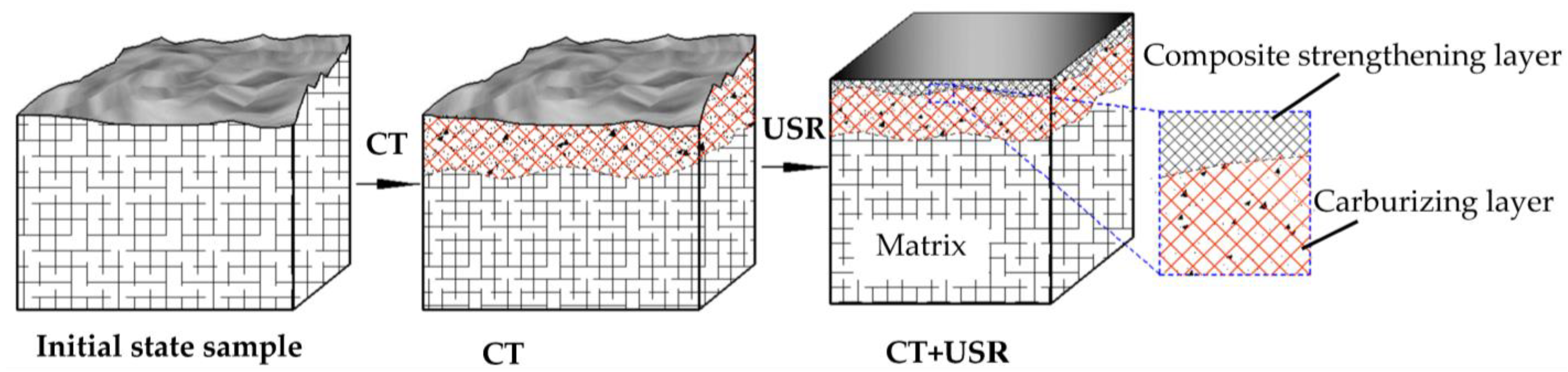
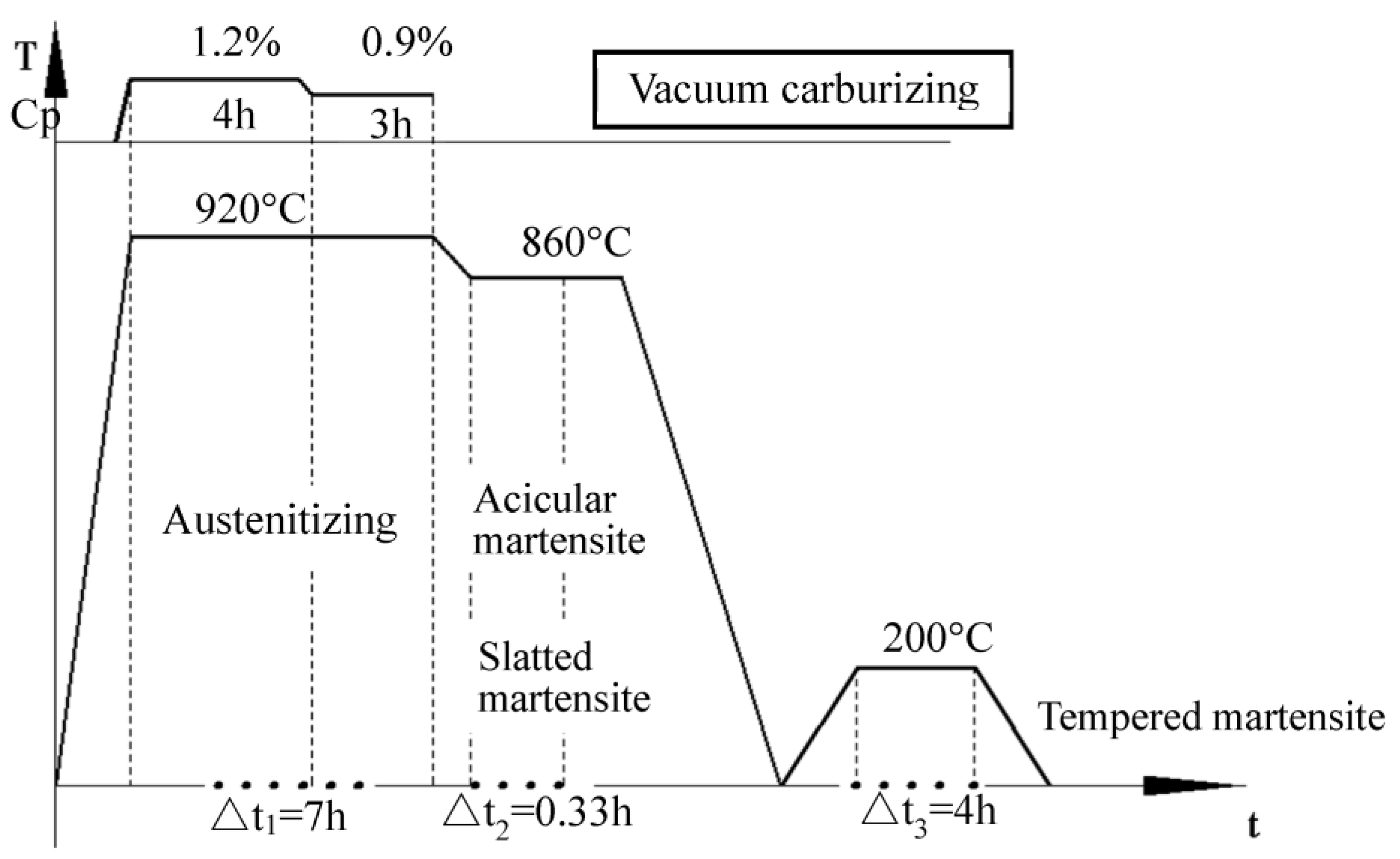
3.1. Sample Preparation

The chemical composition of 20CrNiMo used in this experiment is shown in Table 1. Heat treatment was made for the homogeneous sample obtained after finishing turning and grinding according to the process shown in Figure 3. Particularly, a vacuum carburizing furnace was used for atmosphere carburization at a carbon potential of 1.2% and a temperature of 920 °C for 4 h. After the carbon potential was adjusted to 0.9%, the carburization was continued for 3 h so that the carbon atoms could fully diffuse. The temperature was then decreased to 860 °C. It was cooled to room temperature in the oil bath after 20 min of thermal insulation. A gradient structure that gradually transitioned from high carbon and high hardness on the surface to low carbon and high toughness in the core was obtained. For the treatment of heat treatment temperature, refer to the standard JB/T 11078-2011 of the China Machinery Standards Industry Association. Considering that the Ac3 temperature of 20CrNiMo is about 850 °C, to avoid grain growth, 920 °C carburization and 860 °C quenching are used. Finally, after fine grinding, a rod-shaped sample with a diameter of 10 × 110 mm whose surface roughness did not exceed Ra0.4 μm was obtained. The maximum hardness of the surface layer measured was 719 HV0.1, and the maximum residual compressive stress of the surface layer was 305 MPa.

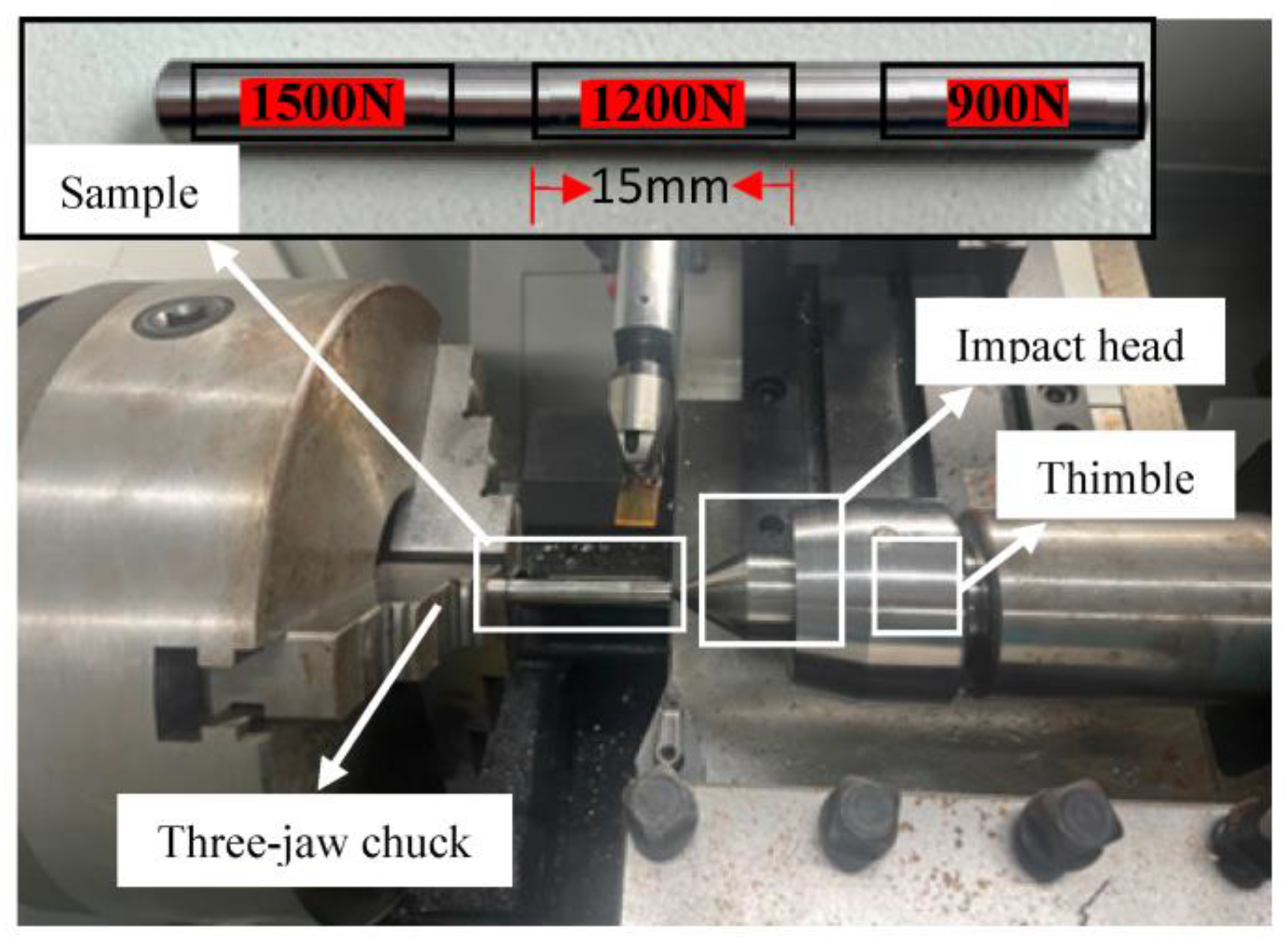
3.2. Ultrasonic Impact Modification Process

HKC30-50 ultrasonic impact modification equipment was used to modify the sample obtained. The specific processing method and region division are shown in Figure 4. The sample was clamped at one end by a three-jaw chuck and supported at the other end with a tip, rotating with the spindle. For the impact head, an SR7 mm hard alloy ball was used. The radial impact strengthening was completed on the cylindrical surface of the sample, driven by a static preload and an ultrasonic load. To reduce the impact of the differences between the samples, the same sample was divided into several areas, and different processing techniques were used for ultrasonic impact modification. The processing width under each process condition was 15 mm, and a safe distance of 7 mm was kept between them to avoid mutual influence.
Static pressure loads of 900 N, 1200 N, and 1500 N were used for 1, 3, and 6 ultrasonic impacts, respectively, in order to explore the effects of static pressure load and the number of times of impact on the surface quality of a 20CrNiMo carburized sample. Based on the optimal static pressure load obtained from the above research work, different regions were selected for repeated impact experiments of 1, 3, 7, 15, and 31 times with a reference to the law of an = an−1 + 2n−1 in order to study further the effect of the number of times of rolling on surface quality. The specific processing parameters are shown in Table 2.

4. Performance Analysis

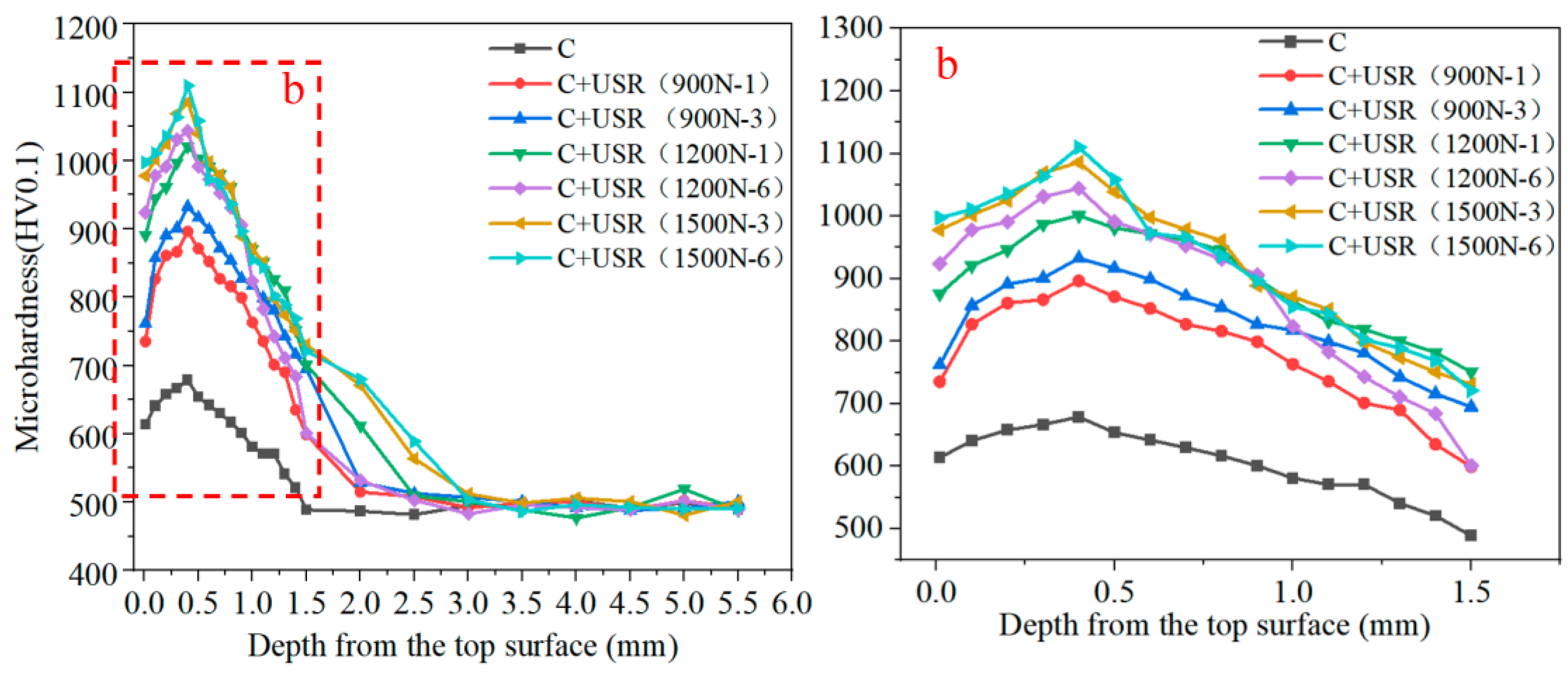
4.1. Surface Hardness Field

Avoiding the starting and ending in each area of ultrasonic impact, the middle section of each strengthening area was selected for cutting and polishing, as well as a Falcon 500 Vickers hardness tester. In addition, a load of 100 gf was applied and kept for 10 s for hardness measurement. Because the change in surface hardness caused by carburizing and strain hardening was relatively large, a measurement was made every 100 µm at a depth of 1.5 mm from the outer surface and every 0.5 mm after 1.5 mm was exceeded. The distribution law of the test sample’s microhardness treated with different processes in the direction of depth is shown in Figure 5. Among them, C and USR, respectively, refer to carburizing and ultrasonic impact modification, of the sample. From the figure, we can see that the hardness of the carburized layer has significantly increased. However, due to a certain degree of decarburization on the test sample’s surface layer in the later stage of carburizing treatment, the maximum hardness value appeared on the subsurface, which was 719 HV0.1. In the test, the surface layer’s microhardness of all the samples after ultrasonic impact increased to different degrees compared to that of the carburized sample and had a similar distribution law. The maximum hardnesses all appeared on the subsurface and gradually decreased in the direction of depth to the matrix hardness. In addition, we can see that the static preload and impact rounds are positively correlated with the highest hardness of the surface layer within the existing parameter range. Also, the increase in the static preload has a more significant effect on the increase in the maximum hardness. After six rounds of impact with a static preload of 1500 N, its microhardness increased to its maximum hardness, which was up to 1110 HV0.1. Carburization treatment significantly increased the surface hardness by increasing the carbon content of the structure, and the plastic strain introduced by ultrasonic impact further intensified lattice distortion, thus obtaining a higher surface microhardness [18]. The combination of the two processes has good effects and application prospects for enhancing the surface performance of 20CrNiMo.

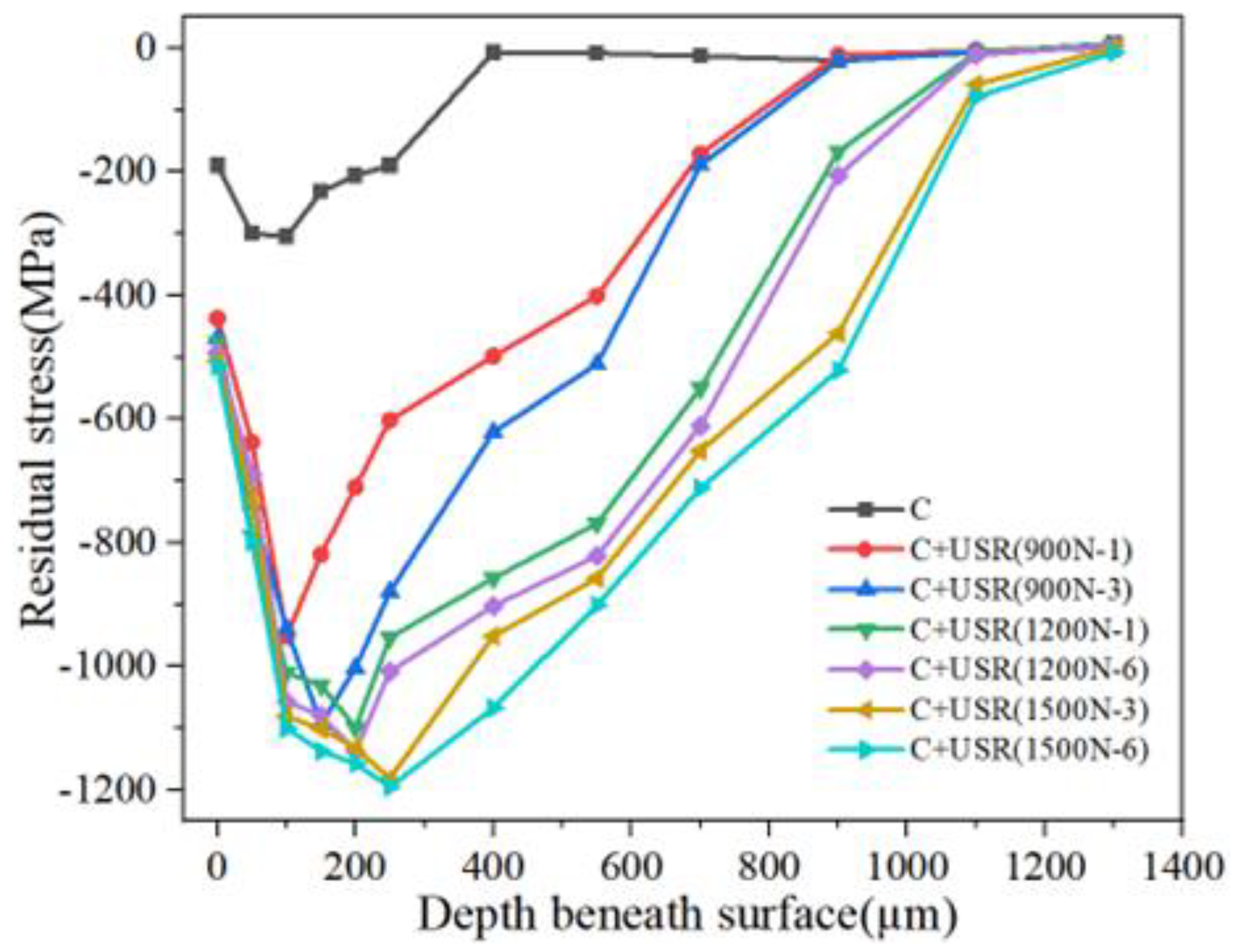
4.2. Surface Residual Compressive Stress Field
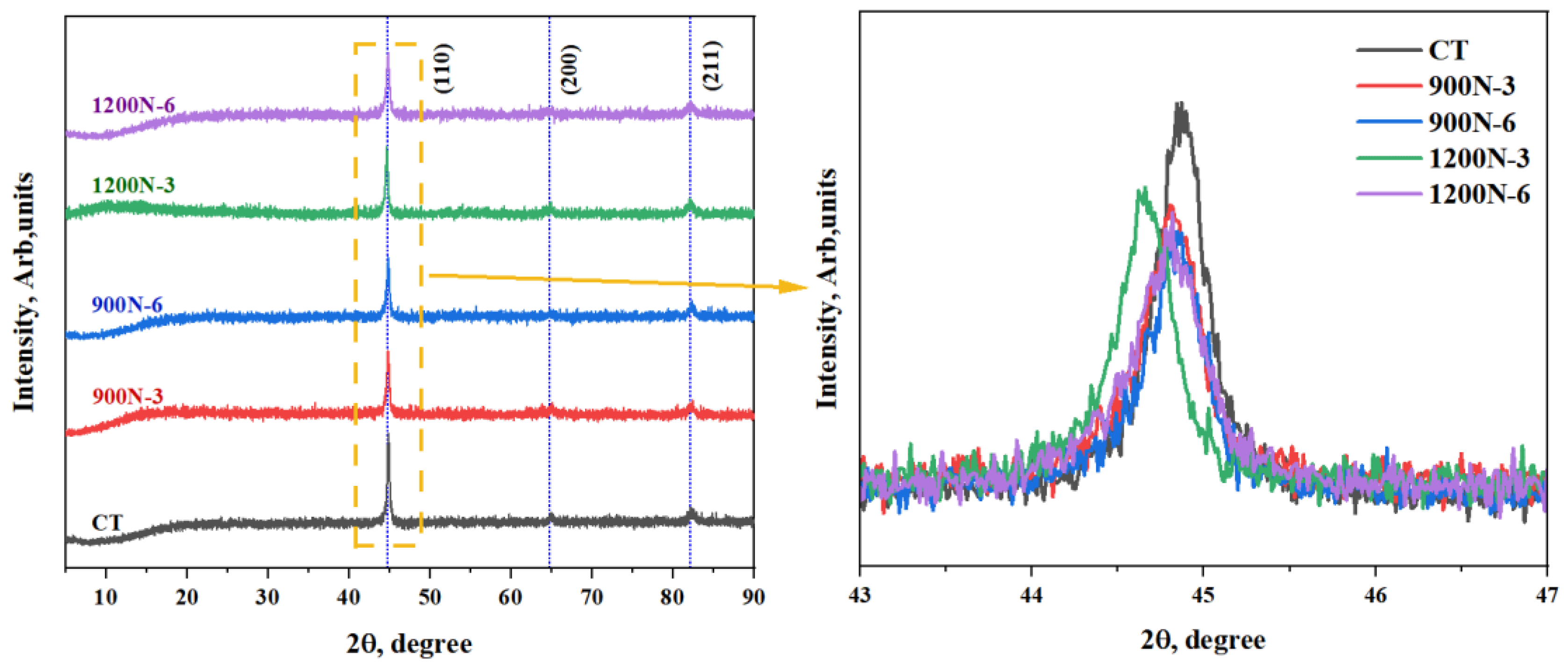
The change rule of the test sample’s residual stress in the direction of depth was measured with a HDS-IX ray stress meter. It was electrolytically peeled with NaCl solution, and the peel depth was measured with a comparison table and a dial indicator. The required peel depth was obtained by controlling the electrolysis time. Considering the relatively big change in residual stress on the surface layer, the residual stress was measured every 50, 150, and 200 µm within 250 µm, 700 µm, and 1300 µm away from the surface. The results are shown in Figure 6. There was a residual compressive stress layer of a certain depth on the test sample’s surface layer. The maximum residual compressive stress of the carburized sample was 305 MPa, which was caused by lattice distortion caused by the interstitial solid solution of carbon atoms in the process of carburizing. Due to the ultrasonic impact, the surface material had a severe plastic deformation, and there was a substantial increase in residual compressive stress. All the maximum values appeared on the subsurface, which was consistent with the distribution law of typical contact load [19]. In addition, we can see that the static preload and impact rounds are positively correlated with the maximum residual compressive stress within the existing range. It is also easier to obtain a large residual compressive stress by increasing the static preload compared with increasing impact rounds [20]. The maximum residual compressive stress reached 1195 MPa after six impact rounds with a static preload of 1500 N. A large residual compressive stress can effectively suppress the initiation and expansion of cracks [21].

4.3. XRD

XRD detection was carried out on different cross-sectional grain states of samples using X’Pert PRO. Figure 7 shows the XRD patterns of 20CrNiMo carburized samples under different rounds of impact. The most obvious diffraction peak was found and its diffraction angle and half peak width were measured. The Debye–Scherrer formula D = kλ/βcosθ calculates the average effective grain size of the measurement area, and the measured values and calculated data are shown in Table 3. In order to determine the organization and structure, according to the experimental results, after comparison, the sample is a cubic crystal system Im-3m (229) spatial group (ICDD 00-050-1296), with no second phase generated According to the measurement results, the effective grain size of the sample without ultrasonic impact is 36.3 nm. In the experiment, the effective grain size of all the samples after ultrasonic impact decreased to varying degrees compared to the carburized sample. This is because severe plastic deformation of the surface material was introduced by ultrasonic impact, resulting in varying degrees of effective grain refinement. In addition, it is shown that increasing the static load and impact round is effective in reducing the grain size. The average effective grain sizes of 900N-3 and 1200N-3 are 31 nm and 29 nm, respectively. Under a static load of 1200 N, the average effective grain size also decreases from 29 nm to 22.7 nm, when the number of impacts increases from three to six.

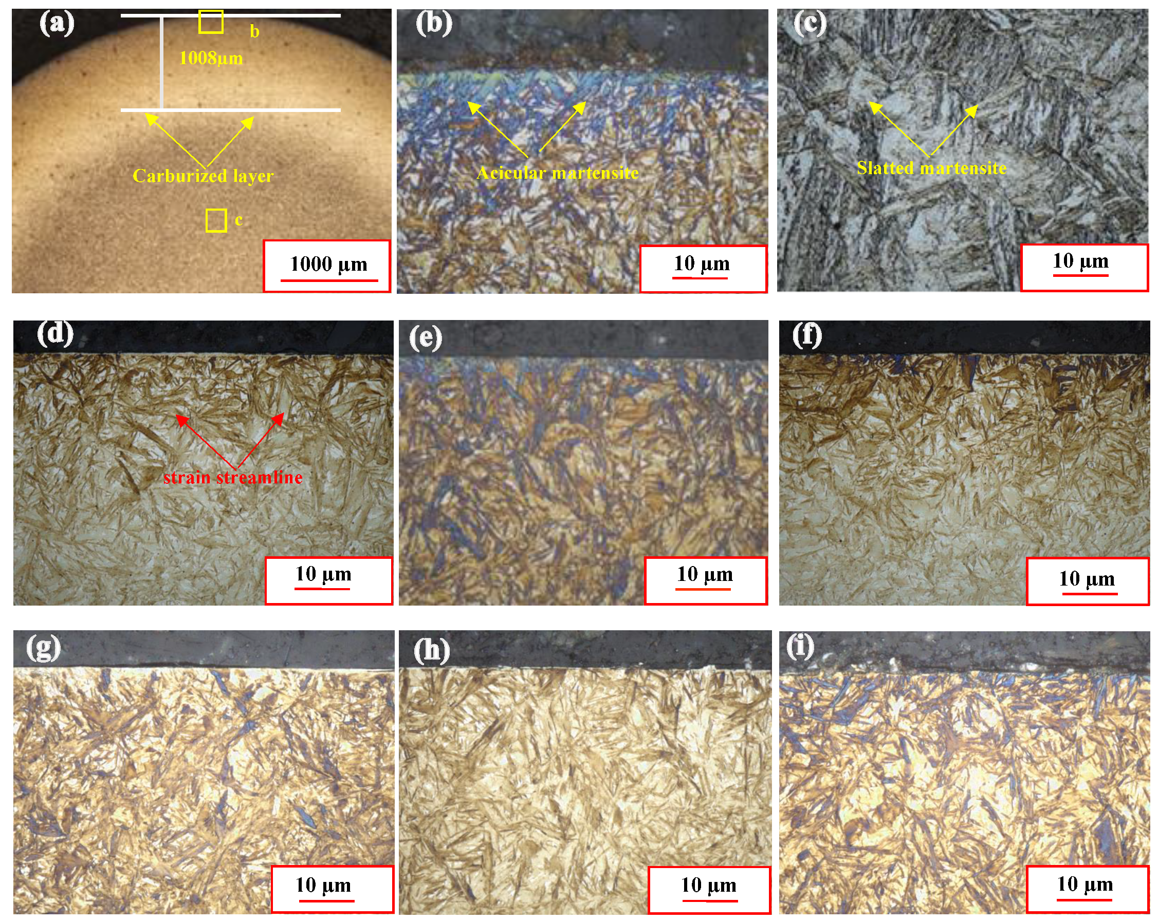
4.4. Microstructure Field on the Surface Layer

The metallographic structures of different sample sections were observed using a Japanese VK-X1000k3D laser scanning confocal microscope. First, the cross-section of the test sample was ground and polished with 400-mesh sandpaper, followed by 2000-mesh sandpaper, until the machining marks disappeared completely and a mirror effect was achieved. Furthermore, 4% nital was then used for etching for 5–8 s in order to obtain the metallographic structure of the corresponding cross-section, as shown in Figure 8. Figure 8a is a metallographic diagram of the carburized sample. We can observe that the depth of the carburized layer is approximately 1230 µm. Figure 8b,c are the magnified pictures of the surface layer and core in Figure 8a. Acicular Martensite and lath Martensite can be observed, respectively, and there is no obvious plastic flow deformation. Figure 8d–i show the metallographic diagram of the cross-section after ultrasonic impact. The depicted surface layers have a certain depth of plastic deformation, in which the structure size is smaller and the content of residual austenite is reduced, indicating that the deformation causes the transformation of residual austenite to Martensite. As the static preload and impact rounds increase, the influence depth of the plastic deformation layer is deepened [22]. In addition, we can see that the surface contour is smoother compared with the original state within the preload of 1200 N. However, when the preload reaches 1500 N, the surface becomes undulated as the impact round increases. In conjunction with the residual stress measurement results, we can conclude that the hardness and strength of acicular Martensite, as well as the maximum residual compressive stress that can be formed, are much bigger than those of the lath Martensite structure. We can also conclude that its structure’s deformation is relatively limited; excessive impact load will cause damage to the surface [23].
The surface morphology of the test sample after different ultrasonic impact modifications was observed using a VK-X1000k3D laser scanning confocal microscope. The results are shown in Figure 9. We can observe that there are many obvious micromachining marks on the surface without ultrasonic impact modification in Figure 9a. Comparing Figure 9b,e, it is evident that ultrasonic impact can effectively enhance most areas of the sample’s surface and make it smoother [24]. By increasing the static preload and impact rounds, machining tool marks on the surface can be enhanced to varying degrees [25,26]. Particularly, after six impacts at a static preload of 1200 N, the tool marks on the surface were basically eliminated. It is the group of processes with the highest surface quality in the test. From Figure 9f, it is evident that when the static preload reaches 1500 N and there are six impacts, some microdefects begin to appear on the surface, as shown by the red area in the figure. In conclusion, increasing the static preload has a greater impact on eliminating machining tool marks from the surface. However, there is a certain upper limit to the static preload for specific parts. When the upper limit is exceeded, the surface quality will deteriorate [27].
The test sample’s surface roughness after treatment with different ultrasonic impact processes was measured using a TR200 handheld roughness meter. The results are shown in Figure 10. The surface roughness of the untreated sample was approximately 0.40 μm. The surface roughness significantly decreased following the ultrasonic impact treatment. After one impact with a static pressure load of 900 N, the surface roughness decreased by 40% and decreased significantly as the static pressure load and number of impacts increased within a specific range. By comparing the ultrasonic impact treatment to different static pressure loads, we can note that the number of impacts a material can withstand decreases as the static pressure load increases. The surface roughness value increased after three times of rolling at 1500 N. At 1200 N, we can note that as the number of impacts increases, the overall Ra value tends to decrease. After more than six impacts, the Ra value started to increase, and other loads had similar upper limits for the number of times of impact. The roughness measurement results are essentially consistent with the change tendency of surface morphology analysis depicted in Figure 8, indicating that the surface quality can be quickly and effectively enhanced under an optimal static pressure load and the number of times of impact. In addition, excessive static pressure and the number of impacts have a negative impact on the performance of the surface.

5. Conclusions

This paper studies the effects of ultrasonic impact process parameters on the surface integrity of 20CrNiMo carburized steel through the USR test on a 20CrNiMo carburized test sample and the characterization of surface roughness, residual compressive stress, microhardness, and other performance parameters. The main conclusions are as follows:
  • Ultrasonic impact can effectively enhance the surface quality of a 20CrNiMo carburized sample within a specific range of static load and impact round without significant deformation. The surface hardness and residual stress are positively correlated with the mean range of static load and impact round, and gradually reach a certain upper limit value as the material’s plasticity losing. The maximum residual stress is up to 1195.36 MPa with the static load of 1500 N and six impact rounds.
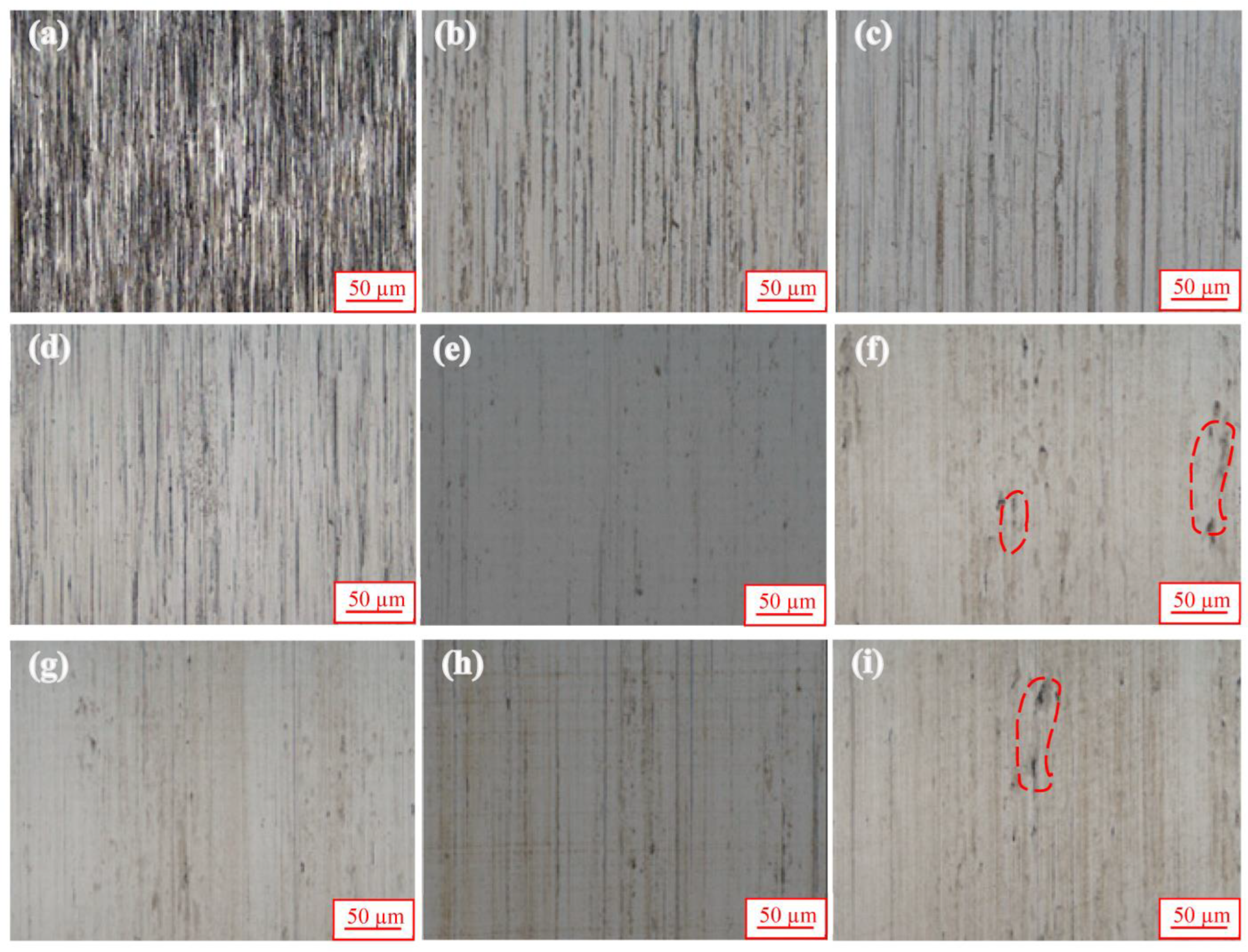
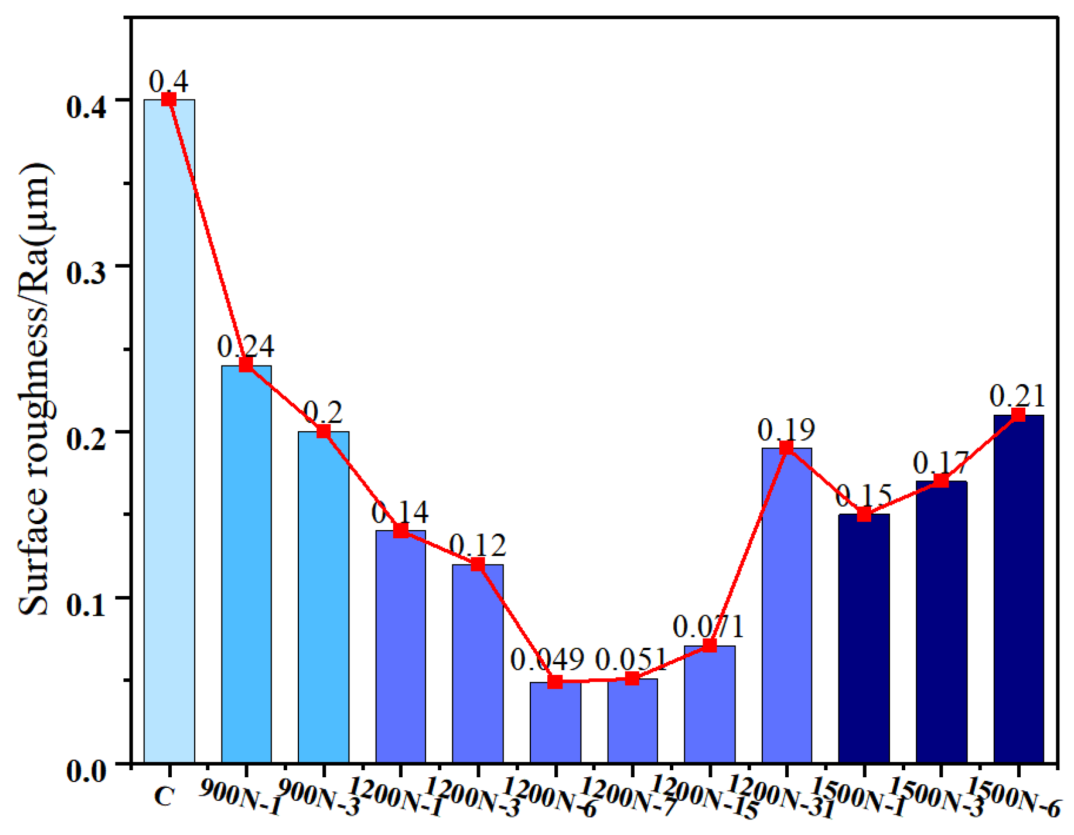
  • The surface roughness and effective grain size of the 20CrNiMo carburized sample gradually decrease as the static load of ultrasonic impact increases. However, when the static load reaches 1500 N, defects appeared on the sample’s surface due to local excessive deformation, and the surface roughness increases sharply. As the impact round increases, the overall Ra value exhibits a decreasing trend. After a certain upper impact round reached, the Ra value will increase significantly.
  • The best surface quality can be obtained after 6 rounds of impact under a static load of 1200 N. When Ra decreases to 0.04 µm, the machining tool marks on the surface are basically eliminated, the surface hardness increases to 1086 HV0.1, and the maximum residual compressive stress on the surface layer reaches 1137.25 MPa.

Author Contributions

Conceptualization, Q.J.; methodology, Q.J.; software, L.Z.; validation, L.Z. and Q.J.; formal analysis, X.C.; resources, L.Z.; data curation, L.Z.; writing—original draft preparation, L.Z.; visualization, Z.Z.; writing—review and editing, Q.J.; supervision, J.C., X.C., J.W. and Z.Z.; project administration, J.W.; funding acquisition, Z.X. All authors have read and agreed to the published version of the manuscript.

Funding

This research was funded by The Natural Science Foundation of Fujian, China (Grant No. 2022H0020, 2022HZ024009), Education Research Project of Fujian Provincial Department of Education, China (Grant No. JAT200252, JAT200237), Jimei University cultivate program of National Nature Science Foundation of China (Grant No. ZP2022011).

Institutional Review Board Statement

Not applicable.

Informed Consent Statement

Not applicable.

Data Availability Statement

The data that support the findings of this study are available within the article.

Conflicts of Interest

The authors declare no conflict of interest.

References

  1. Kayali, Y.; Ucun, I.; Aslantaş, K. Contact Fatigue Failure of a Tapered Roller Bearing Used in a Lorry Wheel. J. Fail. Anal. Prev. 2009, 9, 288–294. [Google Scholar] [CrossRef]
  2. Nakai, Y.; Shiozawa, D.; Kikuchi, S.; Obama, T.; Saito, H.; Makino, T.; Neishi, Y. 4D observations of rolling contact fatigue processes by laminography using ultra-bright synchrotron radiation. Eng. Fract. Mech. 2017, 183, 180–189. [Google Scholar] [CrossRef]
  3. Guo, Y.; Wei, B.; Gu, D.; Wang, Y.; Cao, X. Strength Test and Reliability Evaluation of 20CrNiMo Materials. Mech. Strength 2023, 45, 60–67. [Google Scholar]
  4. Asi, O.; Can, A.C.; Pineault, J.; Belassel, M. The effect of high temperature gas carburizing on bending fatigue strength of SAE 8620 steel. Mater. Des. 2009, 30, 1792–1797. [Google Scholar] [CrossRef]
  5. Qin, S.; Zhang, C.; Zhang, B.; Ma, H.; Zhao, M. Effect of carburizing process on high cycle fatigue behavior of 18CrNiMo7-6 steel. J. Mater. Res. Technol. 2022, 16, 1136–1149. [Google Scholar] [CrossRef]
  6. Wu, H.; Fan, G.; Huang, M.; Geng, L.; Cui, X.; Chen, R.; Peng, G. Fracture behavior and strain evolution of laminated composites. Compos. Struct. 2017, 163, 123–128. [Google Scholar] [CrossRef]
  7. Maleki, E.; Unal, O.; Kashyzadeh, K.R. Effects of conventional, severe, over, and re-shot peening processes on the fatigue behavior of mild carbon steel. Surf. Coat. Technol. 2018, 344, 62–74. [Google Scholar] [CrossRef]
  8. Peng, C.; Xiao, Y.; Wang, Y.; Guo, W. Effect of laser shock peening on bending fatigue performance of AISI 9310 steel spur gear. Opt. Laser Technol. 2017, 94, 15–24. [Google Scholar] [CrossRef]
  9. Xu, G.; Wang, C.; Li, Q.; Zhang, X.; Zhu, Z.; Liang, T.; Yang, B. Effects of ultrasonic rolling on surface performance of 7B85-T6 alloy. Mater. Manuf. Process. 2020, 35, 250–257. [Google Scholar] [CrossRef]
  10. Lu, L.X.; Sun, J.; Li, L.; Xiong, Q.C. Study on surface characteristics of 7050-T7451 aluminum alloy by ultrasonic surface rolling process. Int. J. Adv. Manuf. Technol. 2016, 87, 2533–2539. [Google Scholar] [CrossRef]
  11. Ren, Z.; Li, Z.; Zhou, S.; Wang, Y.; Zhang, L.; Zhang, Z. Study on surface properties of Ti-6Al-4V titanium alloy by ultrasonic rolling. Simul. Model. Pract. Theory 2022, 121, 102643. [Google Scholar] [CrossRef]
  12. Wang, G.; Gu, F.; Qin, J.; Li, J.; Peng, Z. Effect of ultrasonic Impact on Hydrogen Permeability Resistance of 18CrNiMo7-6 alloy steel. Iron Steel 2023, 58, 125–132. [Google Scholar]
  13. Zhang, Y.L.; Lai, F.Q.; Qu, S.G.; Liu, H.P.; Jia, D.S.; Du, S.F. Effect of ultrasonic surface rolling on microstructure and rolling contact fatigue behavior of 17Cr2Ni2MoVNb steel. Surf. Coat. Technol. 2019, 366, 321–330. [Google Scholar] [CrossRef]
  14. Liu, Z.; Zhang, T.; Yang, M.; Zhang, Y.; Wang, D. Influence of ultrasonic rolling parameters on the surface properties of 18CrNiMo7-6 gear steel. Surf. Technol. 2020, 49, 309–318. [Google Scholar]
  15. Li, D.; Chen, H.N.; Xu, H. The effect of nanostructured surface layer on the fatigue behaviors of a carbon steel. Appl. Surf. Sci. 2009, 255, 3811–3816. [Google Scholar] [CrossRef]
  16. Lv, Y.; Lei, L.; Sun, L. Effect of shot peening on the fatigue resistance of laser surface melted 20CrMnTi steel gear. Mater. Sci. Eng. A 2015, 629, 8–15. [Google Scholar] [CrossRef]
  17. Kubiak, K.J.; Liskiewicz, T.W.; Mathia, T.G. Surface morphology in engineering applications: Influence of roughness on sliding and wear in dry fretting. Tribol. Int. 2011, 44, 1427–1432. [Google Scholar] [CrossRef]
  18. Krug, T.; Lang, K.H.; Fett, T.; Löhe, D. Influence of residual stresses and mean load on the fatigue strength of case-hardened notched specimens. Mater. Sci. Eng. A 2007, 468–470, 158–163. [Google Scholar] [CrossRef]
  19. Tan, L.; Zhang, D.; Yao, C.; Ren, J. Effects of Ultrasonic Surface Rolling Parameters on Surface Integrity of TC17 Alloy. J. Mater. Eng. Perform. 2019, 28, 6736–6745. [Google Scholar] [CrossRef]
  20. Tang, J.; Shi, Y.; Zhao, J.; Chen, L.; Wu, Z. Numerical modeling considering initial gradient mechanical properties and experiment verification of residual stress distribution evolution of 12Cr2Ni4A steel generated by ultrasonic surface rolling. Surf. Coat. Technol. 2023, 452, 129127. [Google Scholar] [CrossRef]
  21. Liang, Z.; Li, Z.; Li, X.; Li, H.; Cai, Z.; Liu, X.; Chen, Y.; Xie, L.; Zhou, T.; Wang, X. Experimental study on surface integrity and fatigue life of an ultra-high strength steel by the composite strengthening process of pre-torsion and ultrasonic rolling. Eng. Fail. Anal. 2023, 150, 107333. [Google Scholar] [CrossRef]
  22. Liu, C.; Liu, D.; Zhang, X.; He, G.; Xu, X.; Ao, N.; Ma, A.; Liu, D. On the influence of ultrasonic surface rolling process on surface integrity and fatigue performance of Ti-6Al-4V alloy. Surf. Coat. Technol. 2019, 370, 24–34. [Google Scholar] [CrossRef]
  23. Huang, P.; Wang, Y.; Lin, J.; Cheng, Y.; Liu, F.; Qiu, Q. Effect of ultrasonic rolling on surface integrity, machining accuracy, and tribological performance of bearing steels under different process schemes. CIRP J. Manuf. Sci. Technol. 2023, 43, 143–157. [Google Scholar] [CrossRef]
  24. Wang, H.; Song, G.; Tang, G. Enhanced surface properties of austenitic stainless steel by electropulsing-assisted ultrasonic surface rolling process. Surf. Coat. Technol. 2015, 282, 149–154. [Google Scholar] [CrossRef]
  25. Bozdana, A.T.; Gindy NN, Z. Comparative experimental study on effects of conventional and ultrasonic deep cold rolling processes on Ti–6Al–4V. Mater. Sci. Technol. 2013, 24, 1378–1384. [Google Scholar] [CrossRef]
  26. Xu, X.; Liu, D.; Zhang, X.; Liu, C.; Liu, D. Mechanical and corrosion fatigue behaviors of gradient structured 7B50-T7751 aluminum alloy processed via ultrasonic surface rolling. J. Mater. Sci. Technol. 2020, 40, 88–98. [Google Scholar] [CrossRef]
  27. Liu, P.; Wang, R.; Liu, X.; Ren, R. Effect of Surface Ultrasonic Rolling on Evolution of Surface Microstructure of EA4T Axle Steel. J. Mater. Eng. Perform. 2021, 30, 1270–1279. [Google Scholar] [CrossRef]
Figure 1. Basic principles and schematic diagram of the effect of ultrasonic impact modification.
Coatings 13 01594 g001
Figure 2. Schematic diagram of high-energy conformal surface modification.
Coatings 13 01594 g002
Figure 3. Heat treatment process flowchart.
Coatings 13 01594 g003
Figure 4. Ultrasonic shock strengthening method.
Coatings 13 01594 g004
Figure 5. Hardness distribution under different processes.
Coatings 13 01594 g005
Figure 6. Residual stress distribution under different process treatments.
Coatings 13 01594 g006
Figure 7. XRD patterns of CT, 900N-3, 900N-6, 1200N-3, and 1200N-6.
Coatings 13 01594 g007
Figure 8. Microstructures of different processes: (ac) carburized specimens, (d) C + USR (900N-1), (e) C + USR (900N-3), (f) C + USR (1200N-1), (g) C + USR (1200N-6), (h) C + USR (1500N-3), (i) C + USR (1500N-6).
Coatings 13 01594 g008
Figure 9. Surface morphology under different process treatments: (a) carburized specimens, (b) C + USR (900N-1), (c) C + USR (900N-3), (d) C + USR (1200N-1), (e) C + USR (1200N-6), (f) C + USR (1500N-6), (g) C + USR (1200N-7), (h) C + USR (1200N-15), (i) C + USR (1200N-31).
Coatings 13 01594 g009
Figure 10. Surface roughness of samples under different process treatments.
Coatings 13 01594 g010
Table 1. Chemical composition of 20CrNiMo steel.
ElementCSiMnSPCrNiMoFe
wt. %0.17–0.230.17–0.370.60–0.95≤0.02≤0.020.40–0.700.35–0.750.20–0.30margin
Table 2. USR processing parameters.
GroupSpecimenFrequency
/(kHz)
Load/(N)Axial Feed/
(mm/r)
Spindle Speed/(rpm)Rounds
1USR1239000.12001
2USR2239000.12003
3USR3239000.12006
4USR42312000.12001
5USR52312000.12003
6USR62312000.12006
7USR72315000.12001
8USR82315000.12003
9USR92315000.12006
10USR102312000.12007
11USR112312000.120015
12USR122312000.120031
Table 3. XRD Measurements.
Groupβ Obs. [°2Th]β Std. [°2Th]Peak Pos. [°2Th]β Struct. [°2Th]Crystallite Size [nm]
CT0.2910.05444.9110.23736.3
900N-30.3310.05444.6200.27731
900N-60.3420.05444.7750.28729.8
1200-30.3510.05444.5190.29429
1200-60.4320.05444.7520.37822.7
Disclaimer/Publisher’s Note: The statements, opinions and data contained in all publications are solely those of the individual author(s) and contributor(s) and not of MDPI and/or the editor(s). MDPI and/or the editor(s) disclaim responsibility for any injury to people or property resulting from any ideas, methods, instructions or products referred to in the content.

