Abstract
UV-curable coatings possess numerous advantages, including high production rate, low environmental impact, and customizability, making them highly appealing for a wide range of applications. However, one of the greatest challenges in UV-curable coating is achieving an optimal low-gloss surface by adding matting agents to the coating formulation. Therefore, it is essential to find a suitable matting agent type and an efficient roughness creation method to tailor the surface gloss and generate a controlled low-gloss surface. In this study, modified magnetic particles were added to the coating formulation as matting agents, and the UV curing process was conducted under a magnetic field of 10 to 100 mT. The combined effect of adding magnetic particles and magnetic field during UV curing on the coatings’ surface gloss was investigated. The impact of modification, dispersion, and concentration of magnetic particles and the effect of magnetic field force on the final surface gloss and roughness were assessed. Moreover, the effect of the dispersion and concentration of magnetic particles on the photopolymerization of the coating was evaluated. The result indicated that both the magnetic field force and modification of the magnetic particles impact the surface roughness. A CI-APTES 5% wt. sample cured under a 60 mT magnetic field led to the highest decrease in 20° gloss.
1. Introduction
In recent years, much attention has been devoted to ultraviolet (UV) curing technology since it offers a high production rate, low energy consumption, and coatings with high eco-efficiency [1,2]. This tendency is mainly due to the competitiveness prevailing in the modern world, where manufacturers must adopt innovative and efficient production techniques to deliver high-quality products to customers at competitive prices. Moreover, growing environmental consciousness and governmental regulations compel manufacturers to seek materials and methods with reduced environmental impact, aligning with sustainable practices [3,4].
UV-cured coatings can be applied on various substrates such as metal, plastic, and wood [2,5]. UV-curable topcoats improve the final products’ mechanical properties and chemical resistance by protecting them from scratches, abrasion, and chemical aggressions [1,2,6,7,8,9]. Besides their protective role, they are also responsible for the final product’s appearance (i.e., texture, gloss, and color) [1,3,9].
There is a growing demand for low-gloss coatings due to their natural appearance and capacity to conceal surface imperfections of the substrate. Low-gloss coatings have gained significant popularity across various applications, particularly in wood flooring and interior finishing. However, more work must be conducted to achieve low-gloss UV-curable coatings [10,11]. Indeed, UV-curable coatings contain monomers as reactive diluents and low to no volatile organic compounds (VOCs). As there is no water or organic solvents to evaporate, there is a negligible loss of coating thickness/volume during the curing/drying process compared to conventional solvent-based or water-based coatings. The absence of evaporation and volume contraction results in low surface roughness as the matting agents are barely present near the coatings’ surface [8,12].
A low-gloss appearance can be created by introducing surface roughness to the coating before, during, or after the curing process [13,14]. One of the most common methods to prepare low-gloss coatings is to create surface roughness by adding solid matting agents in the coating formulation before the UV curing process. Silica, aluminum hydroxide, calcium oxide, zinc oxide, and clays are the most widely used inorganic matting agents [10,15,16]. The effectiveness of these matting agents on the surface gloss depends on their presence at the surface of the coating film since the average depth of micro-irregularities created by these agents has a direct effect on the amount of visible light diffused by the surface and hence its surface gloss [10,11,17]. In addition to their presence at the surface, their shape, size, and surface area also impact the surface roughness of the coating [15,18,19]. To obtain a uniform low-gloss coating, it is essential to stabilize the inorganic matting agents in a polymer matrix [13,20]. Therefore, considerable attention has been given to modifying matting agents to ensure uniform distribution in the coating formulation [19,21]. Studies proposed increasing the matting agent concentration in the formulation to compensate for the low volume contraction. Nevertheless, drawbacks of such elevated particle concentrations are high film viscosity, low mechanical properties (scratch resistance and hardness), less coating transparency, and considerable likeliness of particle agglomeration [19,22,23]. Variations in film viscosity significantly impact the application methods and the probability of forming defects in the coating film [12,22,24]. Additionally, a high concentration of matting agents could hinder the absorption of UV light by the photoinitiator and consequently reduce the photopolymerization extent [25]. In addition, particle agglomeration adversely affects the uniformity of surface gloss as well as the mechanical properties of the coating [23,26]. Therefore, obtaining uniform surface roughness and controlling the degree of surface gloss are more challenging for UV-curable coatings than for other coatings [1,3,7].
This study addresses the abovementioned challenges by investigating the effect of adding magnetic particles (MPs) as a new type of matting agent and by developing a new UV curing process to create controlled and uniform surface roughness. To the best of our knowledge, no previous published research has investigated MPs as matting agents in a UV-curable coating formulation. Indeed, many studies on adding iron pentacarbonyl, known as carbonyl iron (CI) MPs, to polymers have been carried out in the biomedical, vibration control, and smart materials fields [27,28]. These publications primarily focused on the effect of MPs on the polymer’s bulk properties, such as mechanical properties and capacity of vibration isolation [29]. Although some of these studies evaluated surface roughness, they all addressed soft polymers and very high MP concentrations (mostly in the 70 to 80 wt.% range) [27,28,29,30,31]. Therefore, more investigations on the potential of MPs in low-gloss surface creation in thermoset coatings are necessary.
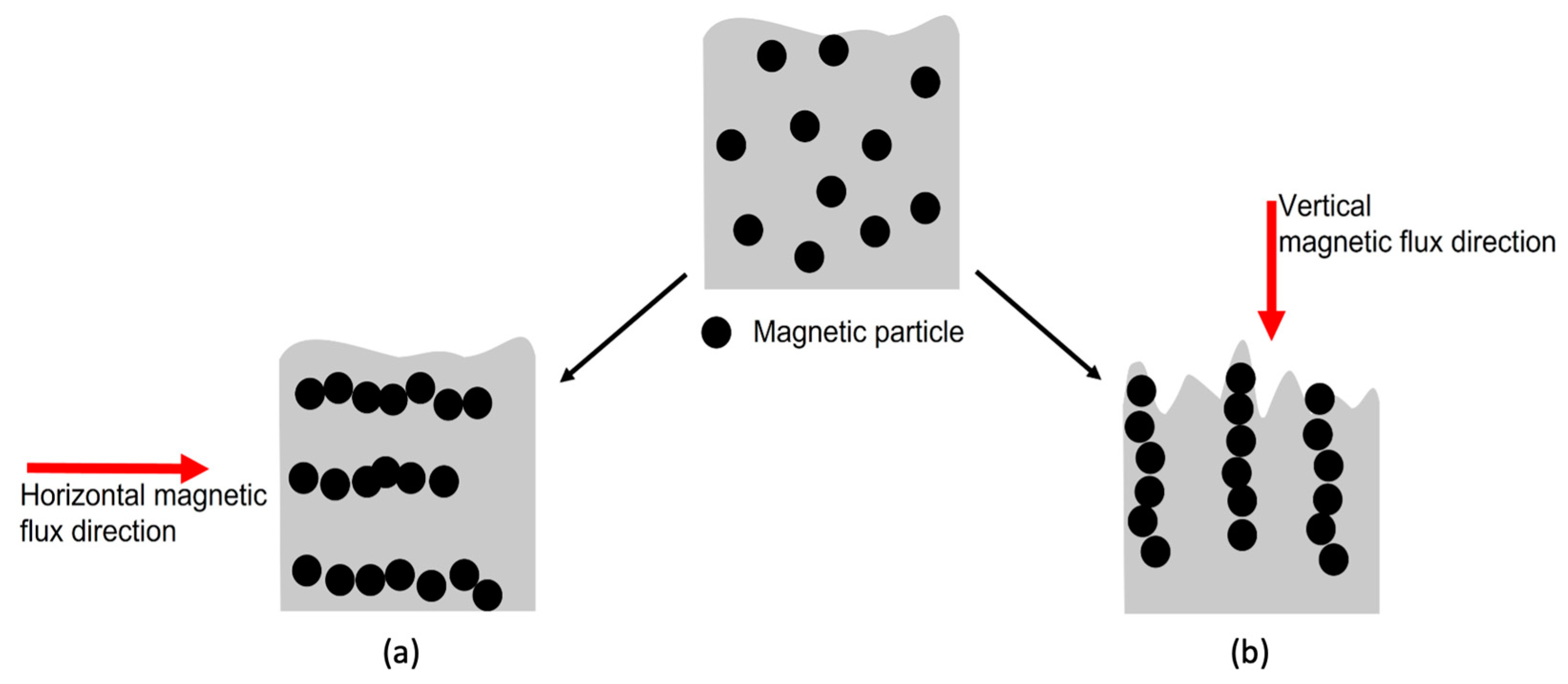
In this study, MPs were employed as matting agents to create a low-gloss UV-curable coating. The UV curing process was carried out in an external vertical magnetic field (MF). Under the influence of this magnetic field, the MPs interacted with one another, aligning themselves in parallel with the magnetic flux. Consequently, they assembled parallel to the magnetic flux, forming a stratified structure extending toward the surface, as shown in Figure 1b [27,32,33,34,35,36]. This could create perturbations at the polymer surface, resulting in a controlled surface roughness and a low-gloss surface [29,30]. Furthermore, to address key challenges, such as MP oxidation and particle agglomeration [37,38,39,40], MPs were modified with an aminosilane (APTES). The grafting efficiency was analyzed via thermogravimetric analysis (TGA) and scanning electron microscopy (SEM). Unmodified and modified MPs were added at 0, 3, and 5 wt.% to the coating formulation, and their dispersion in the cured film was evaluated using a digital microscope. Polymerization kinetics of the UV-curable coatings were monitored via photo-DSC, and the conversion was obtained through FTIR. The surface properties of the coatings were analyzed using a glossmeter and a 3D optical profilometer. Overall, we have demonstrated the ability to manipulate surface roughness and reduce gloss at 20° using MPs and a magnetic field.

Figure 1.
Interaction and assembly of MPs in the coating film under (a) horizontal and (b) vertical magnetic fields.
2. Materials and Methods
CI (Fe(CO)5, Sigma-Aldrich, Oakville, ON, Canada) as an MP has a particle size between 2 and 5 µm. (3-aminopropyl) triethoxysilane (APTES, AB Specialty Silicones, Waukegan, IL, USA), hydrochloric acid (HCl 35%, ACS, Newmarket, ON, Canada), and methanol were used to modify CI. Dipropynyl glycol diacrylate (DPGDA, Canlak, Daveluyville, QC, Canada), aliphatic urethane acrylate (CN9010, Sartomer, Exton, PA, USA), bisphenol A epoxy diacrylate (Genomer 2252-tp20, Rahn, Aurora, IL, USA), diphenyl (2,4,6-trimethylbenzoyl) phosphine oxide (Genocure LTM, Rahn, Aurora, IL, USA), 4,4′-bis diethylamino-benzophenone (Genocure EMK, Rahn, Aurora, IL, USA), and ethyl phenyl (2,4,6-trimethylbenzoyl) phosphinate (Genocure TPO-L, Rahn, Zürich, Switzerland) were used as received.
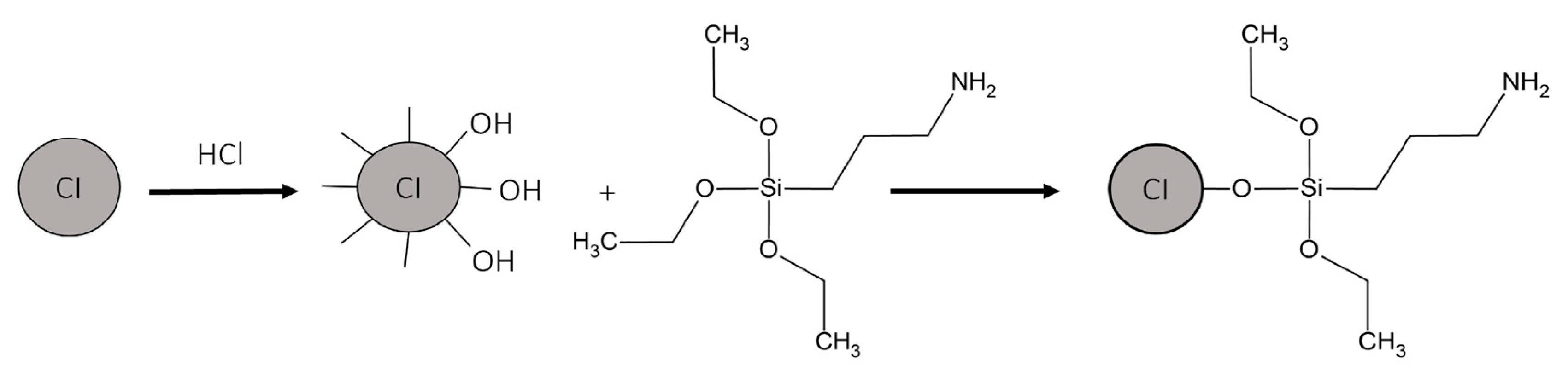
2.1. Surface Modification of Magnetic Particles
HCl (100 mL) was added to CI (20 g) and slightly mixed with a glass stirrer for 20 min. Then, MPs were washed thrice with methanol. Afterward, MPs were added to a flask containing methanol (500 mL) and mixed using an ultrasonic probe (CPX-750, Cole-Parmer, Vernon Hills, IL, USA) for 15 min. Then, the mixture was transferred to a three-neck flask attached to a Teflon agitator and a condenser, and the mixture was heated to 75 °C using a heating mantle. APTES (6 g) was injected very slowly into the mixture, and the mixing continued at 75 °C for 12 h. The functionalization scheme is shown in Figure 2. MPs were separated from the solution by using a magnet and washed five times with methanol. The black residue (the separated and washed MPs) was dried in a vacuum oven for 24 h at room temperature [37].

Figure 2.
Functionalization of CI by APTES.
2.2. Coating Film and Curing Preparation
The composition of UV-curable coating formulations is summarized in Table 1. All formulations were prepared by adding MPs directly to half of the monomer quantity and dispersing them for 10 min in an ice bath using an ultrasonic probe. The mixture was added to the blended oligomers and was dispersed for 20 min by using a high-speed disperser (Dispermat LC3, VMA, Ilmenau, Germany). Since photoinitiators disperse with difficulty, they were first dissolved in the other half of the monomer and then added to the formulations during the last stage of the mixing process. The mixing continued for ten more minutes after all components were formulated together.

Table 1.
Composition of formulations prepared with different MP concentrations and types: F1 (Reference with no MP), F2-B (3 wt.% CI), F3-B (5 wt.% CI), F4-M (3 wt.% Modified CI), and F5-M (5 wt.% Modified CI).
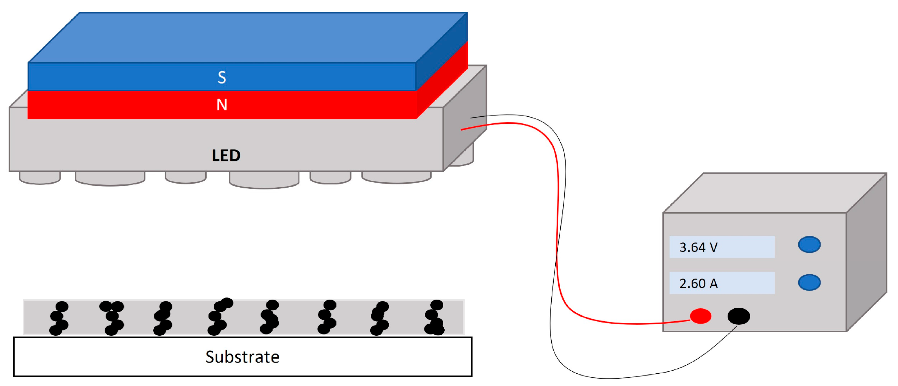
Figure 3 depicts the configuration of the UV lamp and magnet used for the curing process. In this configuration, the MPs in the uncured coating were subjected to the magnetic field to align along the magnetic flux. Then, the film was cured using a 365 nm UV LED lamp for 10 s, and the lamp irradiance at the sample’s surface was determined to be 150 mW cm−2 using a radiometer. Taking into account the magnetic particle alignment within the magnetic field, the vertical magnetic flux configuration (Figure 1) was expected to induce stronger differences in the roughness of the coating than the horizontal one. For that reason, the research was focused on the vertical MF configuration. To produce a vertical magnetic field (Figure 1b), a neodymium magnet of 40 × 40 × 20 mm (MiSUMi, Schaumburg, IL, USA) was installed above the UV lamp, and the sample was placed under the lamp at a distance of 2 cm. Three different MF intensities of 10, 60, and 100 mT were used to assess the effect of the magnetic field strength on the surface roughness. It is worth noticing that this range of magnetic field could be easily produced on an industrial scale. The magnet was moved until the different magnetic field intensities of 10, 60, and 100 mT were obtained. This intensity was measured using a magnetometer (TD8620, VTSYIQI, Hefei, China). The uniformity of the magnetic field intensity was calculated based on the variation in the average vertical component of the magnetic field intensity along the central line of the observation zone and from an average of 20–30 points. According to the simulations conducted using FEMM software (version 4.2.), the deviation of the magnetic field intensity for the 60 mT and 100 mT configurations was determined to be ±0.34% and ±0.45%, respectively.

Figure 3.
Schematic of UV lamp and magnet configuration.
Formulations were applied at a thickness of 12.7 µm (0.5 mil) by using a rod applicator (#8, BYK, Wesel, Germany) on two different substrates (glass and LENETA paint test chart) in two groups. While the film was freshly applied and uncured, the first group of samples was placed under the UV lamp magnet (UV-MF) setup, and the lamp was turned on. The second group of samples was cured without a magnet (UV). Exposure time for both groups, UV and UV-MF samples, was varied between 0 and 10 s, and each measurement was repeated three times.
2.3. Characterization
2.3.1. Characterization of MPs
The morphology of the MPs before and after modification was examined through scanning electron microscopy (SEM) using a Quanta 250 microscope (FEI, Hillsboro, OR, USA) with a consistent acceleration voltage of 15 kV. The thermal behavior of the MPs before and after modification was also measured through thermal gravimetric analysis (TGA) using TGA/DSC3 3+ (Mettler Toledo, Greifensee, Switzerland). TGA was performed in the 35–650 °C temperature range with a 10 °C min−1 heating rate and under a 50 mL min−1 air and nitrogen flow rate.
2.3.2. Characterization of UV-Cured Coatings
To evaluate the impact of MPs on the photopolymerization of the coatings, the conversion degree was calculated using a photo-DSC instrument (DSC822, Mettler Toledo, Switzerland) equipped with a Lightning cure LC5 (Hamamatsu, Japan) high-pressure Mercury-Xenon lamp emitting UV light in the 240 to 400 nm wavelength range. Samples of 2.5 ± 0.1 mg of uncured formulations were exposed to UV light at 50 mW cm−2 radiation intensity for 1 min at 30 °C in triplicates. The conversion of C=C double bonds was calculated through the integration of the area under the exothermic peak using Equation (1):
where is the recorded heat enthalpy released at time t. is the theoretical heat enthalpy calculated using Equation (2), and β, x, and M are, respectively, the functionality, mass concentration, and molecular weight of each compound in the formulation. is the polymerization enthalpy of the acrylate bond, which is 86 kJ mol−1 [41]. The conversion of the acrylate double bonds was measured by using an FT-IR spectrometer (Invenio R, Bruker, USA) equipped with an attenuated total reflectance (ATR) module.
FTIR was performed on uncured and cured films after 3, 5, and 10 s of UV exposure. Measurements were executed using a 4 cm−1 resolution in the spectral range of 400–4000 cm−1 for 32 scans. The conversion can be determined using the absorbance peak intensity for acrylate bonds at 810, 1405, and 1636 cm−1 before and after the photopolymerization [42]. In this study, the conversion percentage was obtained using Equation (3) using the area under the 1636 cm−1 absorption peak [43,44]:
where and are integrals of the absorption peak at 1636 cm−1 before and after UV exposure.
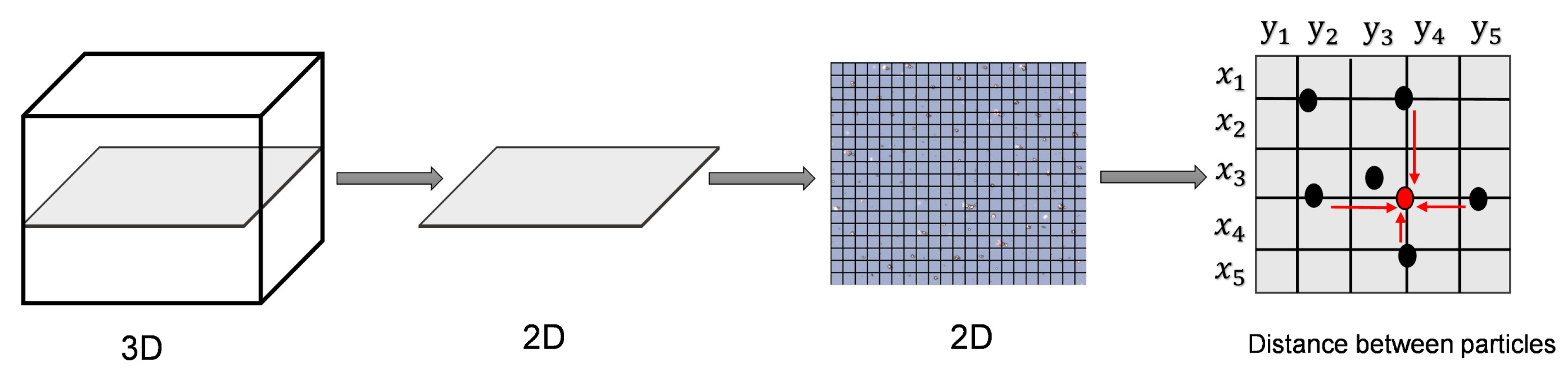
The dispersion of modified MPs in the cured film applied on glass was evaluated using a digital microscope (VHX7000, Keyence, Osaka, Japan). The degree of dispersion was calculated using the method depicted in Figure 4 and the software embedded with the instrument. The dispersion was evaluated for both modified and bare MPs based on the free path spacing between adjacent MPs [45,46]. The distance distribution between a particle chain and its adjacent particle chains was used to characterize and quantify the uniformity [45].
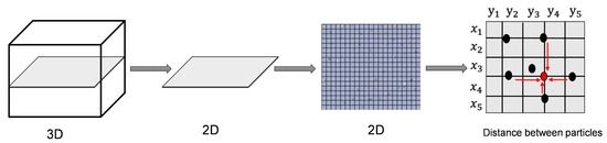
Figure 4.
Schematic of distance measurement by microscopy.
The surface roughness of the coated samples was measured through 3D images taken using a VHX-7000 Keyence digital microscope. The roughness parameter used in this study was the arithmetical mean roughness (Ra), which is defined by Equation (4) [47]:
where l is the sampling length and Z(x) is the profile height. The values of Ra were recorded at ten randomly selected lines on the coated area on the glass substrate.
The specular gloss of the cured surface was measured using a glossmeter (micro-TRI, BYK, Columbia, MD, USA) at 20° and 60° incidence angles. The glossmeter was placed on the cured film on the LENATA paint test chart, and the values were recorded at three randomly selected spots. The glossmeter calculates the intensity of the specular reflection of the sample () relative to the specular reflection of black polished glass as the reference standard (). The average gloss () is defined according to Equation (5) [48,49]:
3. Results
3.1. Morphology and Thermal Analysis of MPs
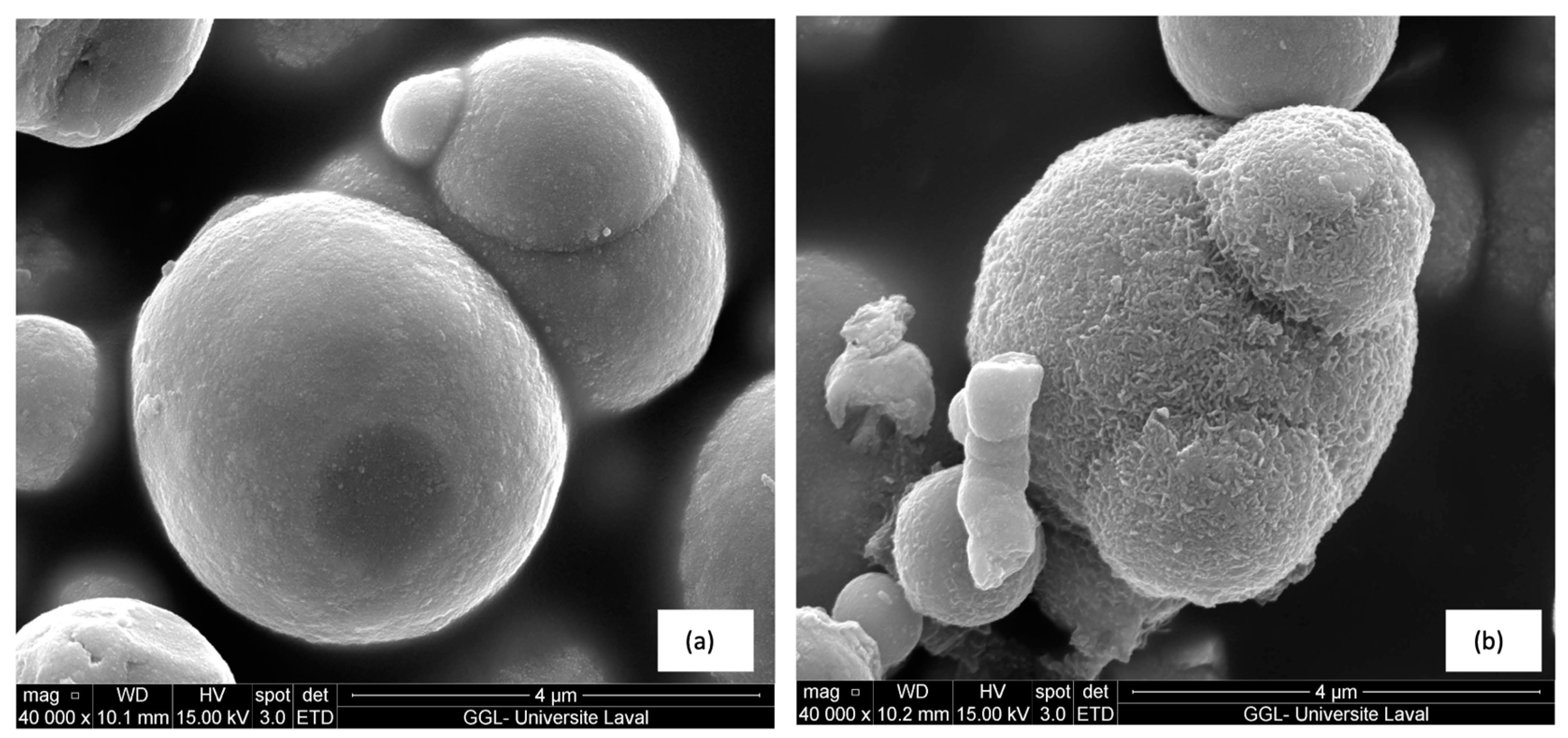
SEM images of MPs before and after modification by APTES are shown in Figure 5. Figure 5a shows that the surface of CI particles before modification is smooth, while, as depicted in Figure 5b, the texture of the CI surface becomes rougher after modification. According to the previous research of An et al., supporting the conclusion that a rough surface results from the effective functionalization of MPs with APTES, successful functionalization of the MP surface was achieved with APTES [37].

Figure 5.
SEM images of CI (a) before modification and (b) coated by APTES.
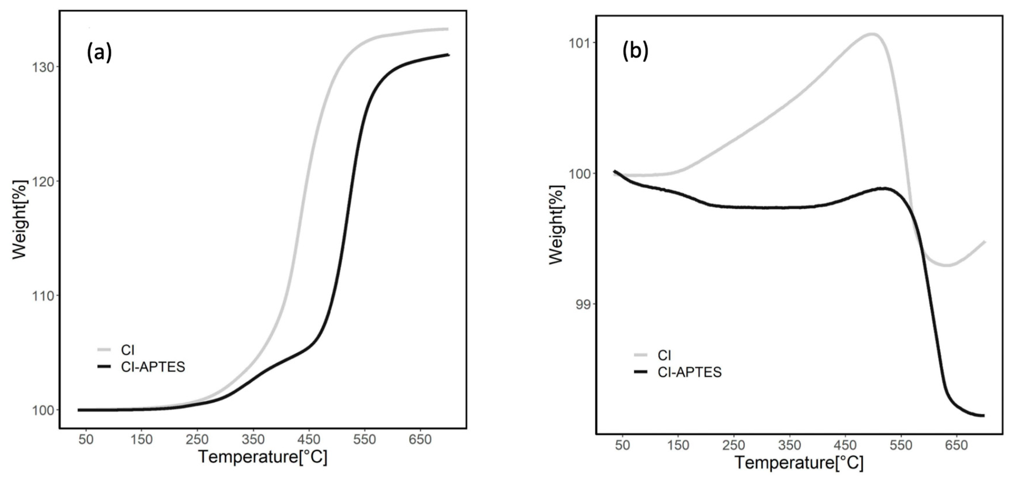
Figure 6 presents the TGA results indicating the thermal stability of MPs before and after modification by APTES under air (a) and nitrogen (b) flows. In the air atmosphere, MP curves show an increase in weight during heating due to the oxidation of CI to ferric oxide [50]. The total weight increased by 33.5% for CI and 31% for CI-APTES. The weight of CI particles started to increase significantly at approximately 350 °C, while the sharp weight increase for CI-APTES began at 500 °C. This temperature shift showed a higher resistance to oxidation in MPs modified, which could be attributed to the APTES layer. This layer plays the role of a barrier limiting the exposure of MPs to oxygen by forming a shell around the surface of MPs [51]. Under the nitrogen flow, the weight of the MPs slightly decreased at 650 °C. For the CI particles, the weight increased (1.1%) up to 450 °C, which could be attributed to possible oxidation since the nitrogen flow or the CI may still contain impurities. Over 500 °C, the weight of CI slightly decreased. However, the weight of CI-APTES showed a steady trend up to 500 °C due to its oxidation resistance. Beyond this temperature, MPs’ degradation started, leading to an eventual slight weight loss [52]. Total weight loss for CI-APTES was around 1.9%, while for CI, the loss was about 0.5%.
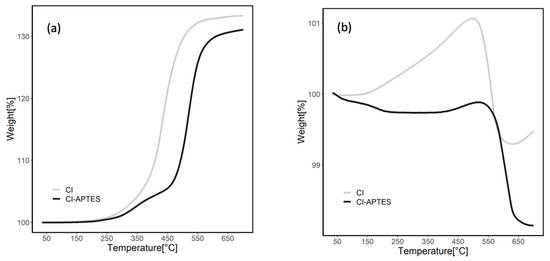
Figure 6.
Total mass residue of MPs before and after CI modification under (a) airflow and (b) nitrogen flow.
3.2. Conversion Analysis of MPs UV-Curable Coatings
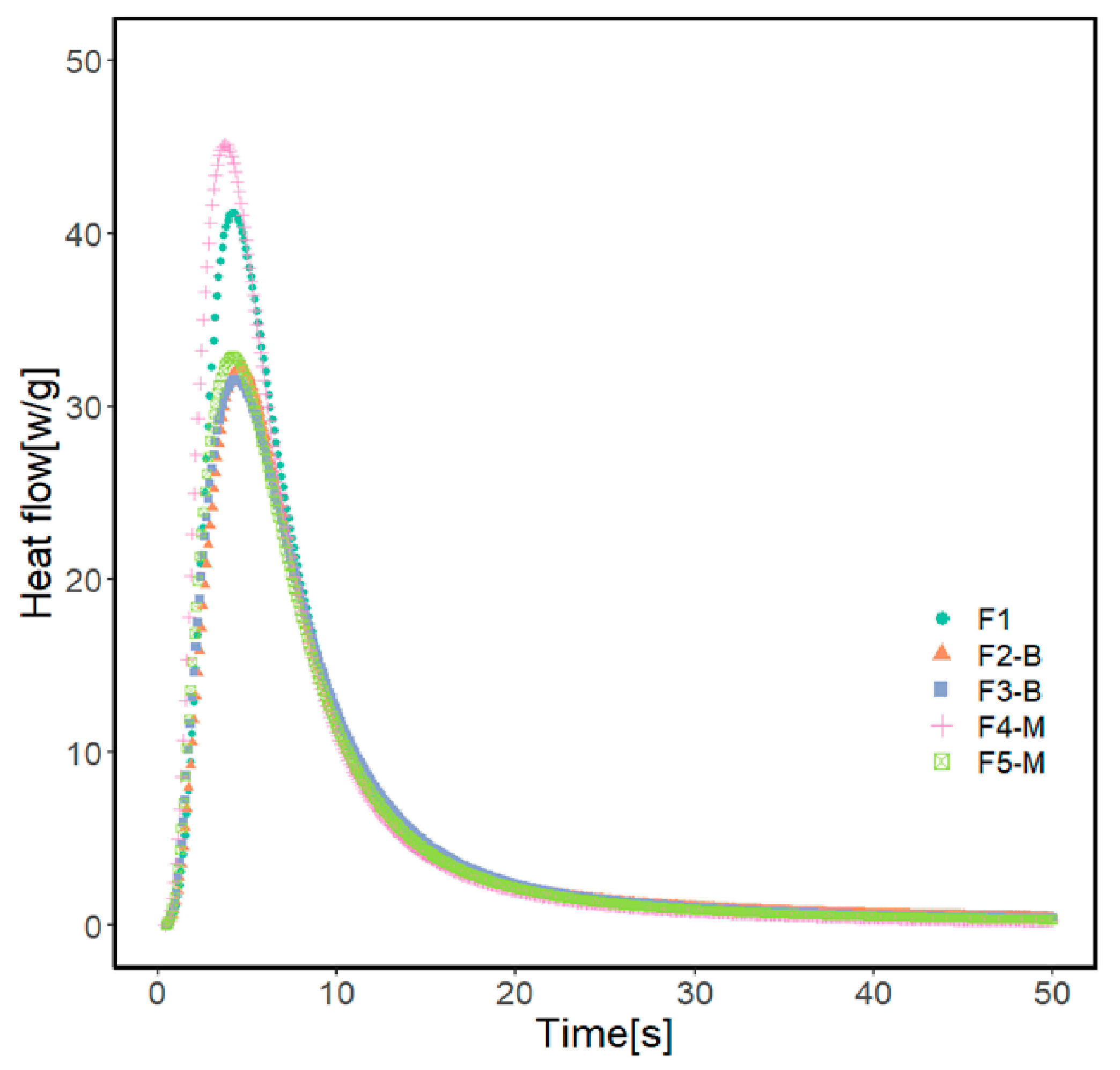
Photo-DSC was used to monitor the photopolymerization behavior of UV-curable acrylate formulations containing various concentrations of MPs. Table 2 and Figure 7 present the results of photo-DSC measurements, and Figure 8 illustrates the conversion of formulations. According to the measurement results, the heat flow enthalpy () and conversion (α) remain approximately constant with increasing MP content in the formulation.
Table 2.
Polymerization kinetic analysis results for the acrylate formulations.
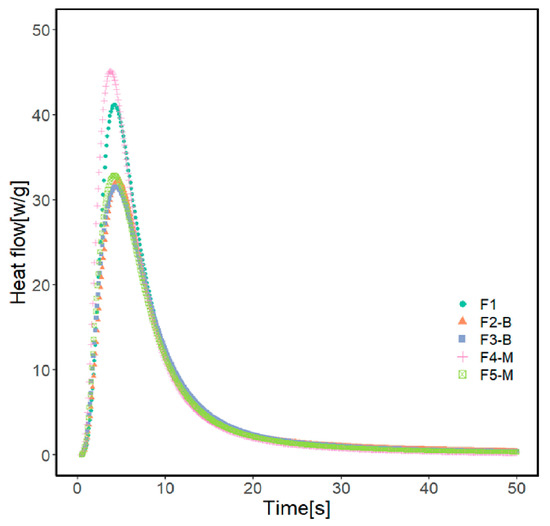
Figure 7.
Photo-DSC exotherm of the UV-curable coating formulations.
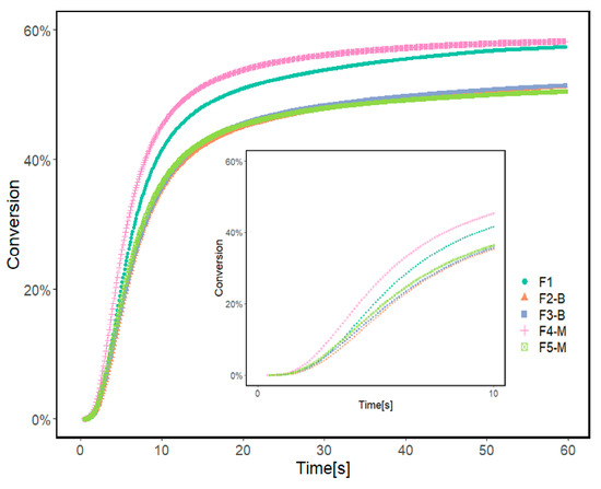
Figure 8.
Conversion rate of reference formulation (F1) and formulations prepared with 3 and 5% wt. of MPs before and after modification calculated from Photo-DCS results.
Formulations containing 3 and 5% of CI-APTES or 5% CI show a similar conversion of 51%. The formulation with 3% CI-APTES achieved the highest conversion of 58% and the maximum heat flow of 45.5 Wg−1 among all the studied formulations, which is closer to the value obtained with the reference (F1). Since all formulations’ mixing time and composition were kept constant, better particle dispersion for 3% CI-APTES is believed to be the main contributor to this higher heat flow. Better particle dispersion promotes higher scattering of the incident UV light and accordingly enhances the photoinitiation efficiency of UV curing [19,53,54]. On the other hand, the presence of CI (non-modified) MPs, as compared to CI-APTES, and higher MP concentration in the formulation leads to higher aggregates of MPs, which tend to hinder the penetration of UV light into the resin matrix and hence reduce the efficiency of the photopolymerization process [54].
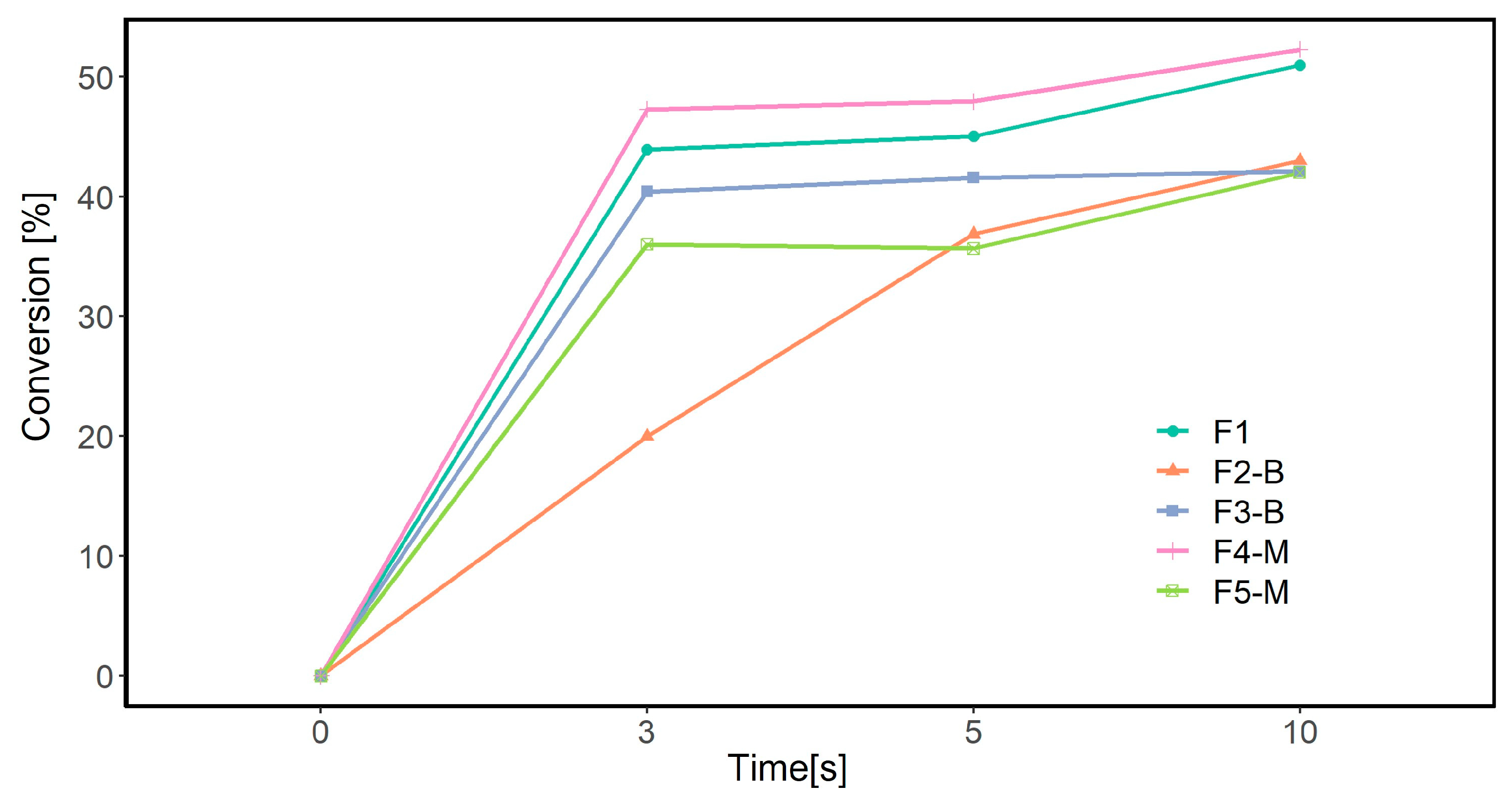
FTIR analysis was conducted to determine the polymerization extent of acrylates from the absorption of the acrylate double bond. Figure 9 illustrates the degree of conversion in different MP formulations based on the disappearance in the peak area at 1636 cm−1 CH2=CH2 stretching at three different irradiated UV doses.
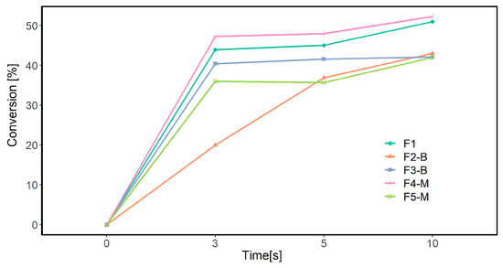
Figure 9.
Conversion rate calculated from FTIR-ATR results.
For the neat formulation (F1), the conversion rate increased to 50% within 10 s. The double bond conversion, calculated from the FTIR spectra, showed a similar trend to the photo-DSC experiments, where the highest conversion degree (52%) was observed for the F4-M formulation containing 3 wt.% CI-APTES. However, the difference in the calculated conversion percentages between the FTIR-ATR method and photo-DSC is believed to be due to the differences in the measurement parameters used for these methods, such as the lamp type, the UV exposure duration, and the methods used to calculate the conversion rate. The main difference between these methods is that FTIR measures the conversion percentage of acrylate groups, whereas photo-DSC measures the overall conversion of the formulation. Moreover, obtaining similar trends for both analyses further consolidates the conclusion of the effect of particle dispersion on UV curing efficiency.
3.3. MPs Dispersion in Formulations
The boxplots and histograms presented in Figure 10 demonstrate the arrangement of MPs in the polymer matrix and the distance between them in the form of free path spacing between adjacent MPs. The box plots represent the average distance between MPs in F2-B and F4-M formulations. The modified MPs exhibited a slightly greater average free path spacing compared to the bare MPs. This can be attributed to the surface functionalization process of the MPs treated with APTES reducing the tendency to aggregate, which leads to a better distribution of MPs in the cured film. Amino functional groups of the APTES enhanced the compatibility and interfacial interactions between the modified MPs and the polymer matrix [38,55]. This improved dispersion can also be seen in the histograms of both samples at 0 mT, where the spacing distribution for modified MPs shows two populations, with the latest located at higher values than for bare MPs.
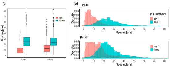
Figure 10.
(a) Box plot diagram and (b) histograms of average free path spacing for CI 3% and CI-APTES 3% samples cured under UV and UV-MF.
However, applying the magnetic field during curing leads to the redistribution and assembly of particles within the film. As a result of the magnetic flux, more evenly distributed particle chains were obtained. This redistribution and assembly result can be observed in the noticeable shift of box plots and the significant movement of histograms toward higher average free path spacing values for the UV-MF-cured samples.
In addition, the histograms of average spacing for the UV-MF-cured samples transform to more normally distributed values representing more evenly distributed MPs in the film upon applying the MF. The interaction between MP chains under the magnetic field causes them to assemble at almost equal spaces from their neighbor chains, giving rise to a similar density distribution [56,57].
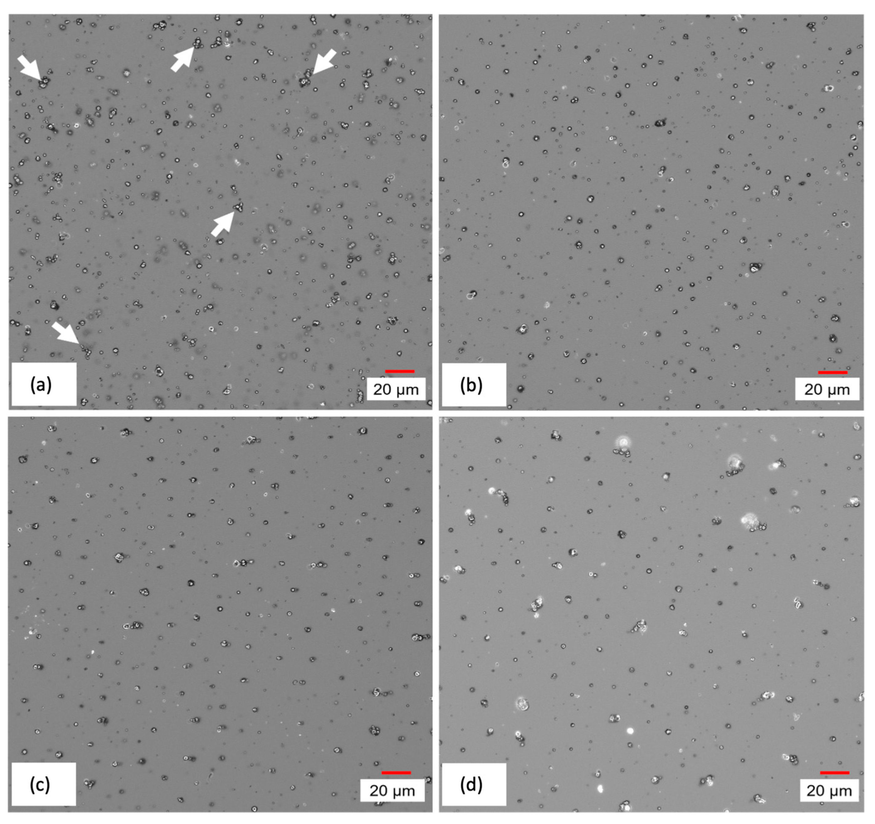
Figure 11, which provides images of the surface of cured CI films, depicts the redistribution of MPs due to the application of magnetic field during the curing process. Moving from (a) to (d), it can be seen that unevenly distributed and agglomerated MPs, indicated by arrows, are replaced by more evenly distributed vertical chains after the application of an increasing magnetic field.
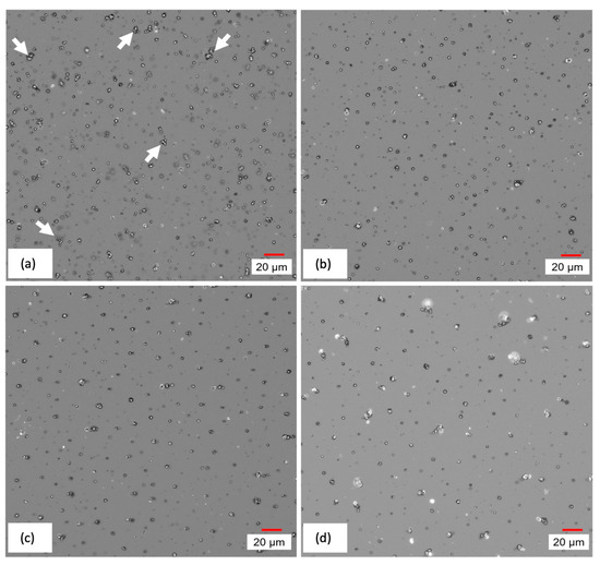
Figure 11.
Digital microscope images of CI film cured under (a) 0 mT, (b) 10 mT, (c) 60 mT, and (d) 100 mT magnetic intensity.
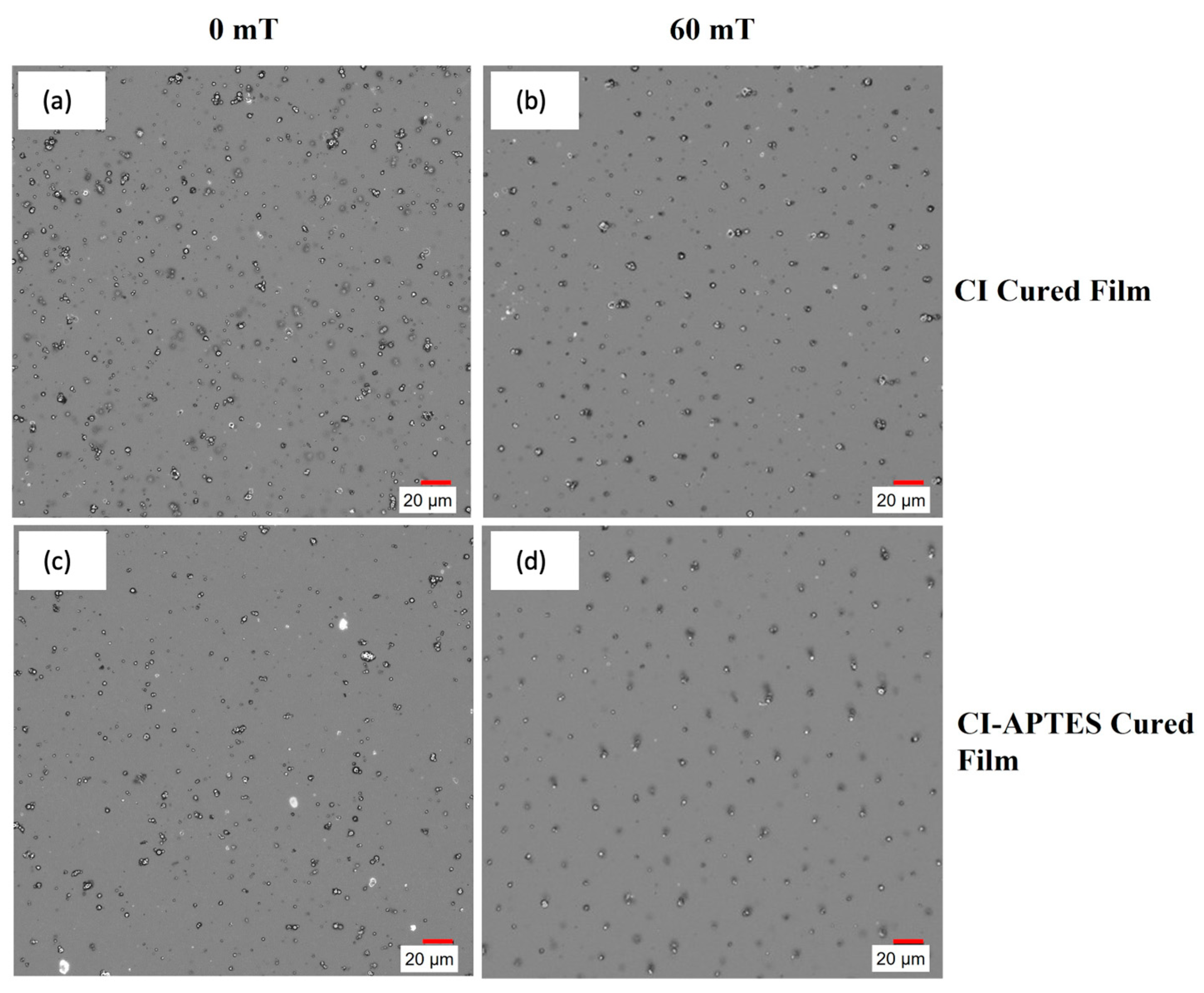
However, for CI-APTES samples, (Figure 12c,d), MPs are better distributed within the film following an increasing trend with the magnetic intensity. This is due to the formation of particle chains and the higher agglomeration of MPs under the impact of the magnetic field. Compared to CI particles in Figure 12a,b, the CI-APTES particles (Figure 12c,d) are more evenly distributed in the volume of the film before applying the magnetic field, as less agglomeration and a lower concentration of MP on the surface can be observed (cross-section images are available in Supplementary Materials Figures S1 and S2). Meanwhile, by applying a strong magnetic field (60 mT and higher), the particles in both CI and CI-APTES samples (Figure 12b,d) are positioned in vertical particle chains at almost equal horizontal distances.

Figure 12.
Digital microscope images of (a,b) CI and (c,d) CI-APTES cured films under 0 and 60 mT magnetic intensity, respectively.
3.4. Surface Roughness of the Coatings Cured by UV and UV-MF
The surface roughness (Ra) of four formulations (F2-B, F3-B, F4-M, and F5-M) cured on a glass substrate is presented in Figure 13. The leftmost column for each formulation represents the UV-cured samples without a magnetic field (0 mT), while the three other columns represent the UV-MF samples at 10, 60, and 100 mT, respectively. In the absence of a magnetic field (0 mT), UV-cured films of CI (F2-B and F3-B) are rougher than UV-cured CI-APTES films (F4-M and F5-M) due to the higher agglomeration of non-modified particles and the higher presence of MPs at the surface. In the CI-APTES formulations (F4-M and F5-M), the modified MPs are more evenly distributed in the volume of the base formulation, which consequently leads to lower roughness [58]. As shown in Figure 13, the F4-M sample (3 wt.% CI-APTES) shows an increase in surface roughness once the magnetic field is applied. At 0 mT, surface roughness was 0.95 µm, and then there was an increase in the roughness of the UV-MF films. Ra values were measured to be 1.18, 1.05, and 1.29 µm for the MF intensities of 10, 60, and 100 mT, respectively. However, the obtained standard deviations do not allow for differentiation between the roughness measurements of samples at the three MF intensities. For the F5-M sample (5 wt.% CI-APTES), the roughness obtained at 0, 10, 60, and 100 mT was higher than that for F4-M (3 wt.% CI-APTES). In fact, the addition of higher quantities of particles increases the film’s surface roughness. Finally, the F5-M sample clearly demonstrated that the intensity of the applied magnetic field (10, 60, or 100 mT) had no impact on the final surface roughness. Ra values were recorded as 1.58, 1.62, and 1.63 µm, respectively. For the F2-B and F3-B samples, the surface roughness was higher without a magnetic field (0 mT) compared to the UV-MF films with 10, 60, and 100 mT. In fact, the MPs, including the agglomerated ones, redistributed within the film when the magnetic field was applied, resulting in rearrangement and the formation of vertical particle chains. Therefore, the surface roughness decreased with increasing magnetic intensity. As the magnetic flux increased, more agglomerated and surface MPs transformed into particle chains and aligned themselves with the magnetic flux.
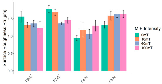
Figure 13.
Results of surface roughness (Ra) measurements for UV-cured film at 0, 10, 60, and 100 mT of magnetic intensity.
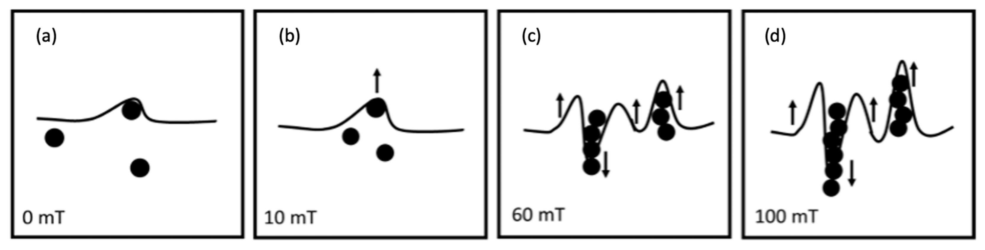
The roughness increase for CI-APTES formulations (F4-M and F5-M) under the influence of an external magnetic field, as shown in Figure 13, could be related to the assembly of MPs and the formation of MP chains under the magnetic field, leading to a higher presence of MPs at the film surface [58]. Indeed, once a magnetic field of 10 mT is applied, the surface is slightly deformed due to the displacement of some MPs toward the surface. Under higher magnetic intensities (60 mT and higher), the tendency of MPs to move increases, and close particles join to form a chain. While some chains move downward in the film, magnetic forces push others toward the surface. As more MPs are added to the chain, the balance between the gravitational force and the magnetic force acting on the chain is impacted in favor of the gravitational force, and, hence, the chain tends to move downward [59]. On the other hand, moving the chain downward repulses the adjacent film upward, creating a surface morphology with peaks and valleys [60]. Figure 14 depicts the process of surface roughness creation in UV-cured and UV-MF-cured samples. From the results obtained before, beyond a certain magnetic intensity, the impact on the peak to valley height and the roughness (Ra) becomes negligible between the magnetic fields.

Figure 14.
Surface deformation and MP redistribution upon applying different levels of magnetic field (0–100 mT) (a–d) during curing.
3.5. Gloss Measurements
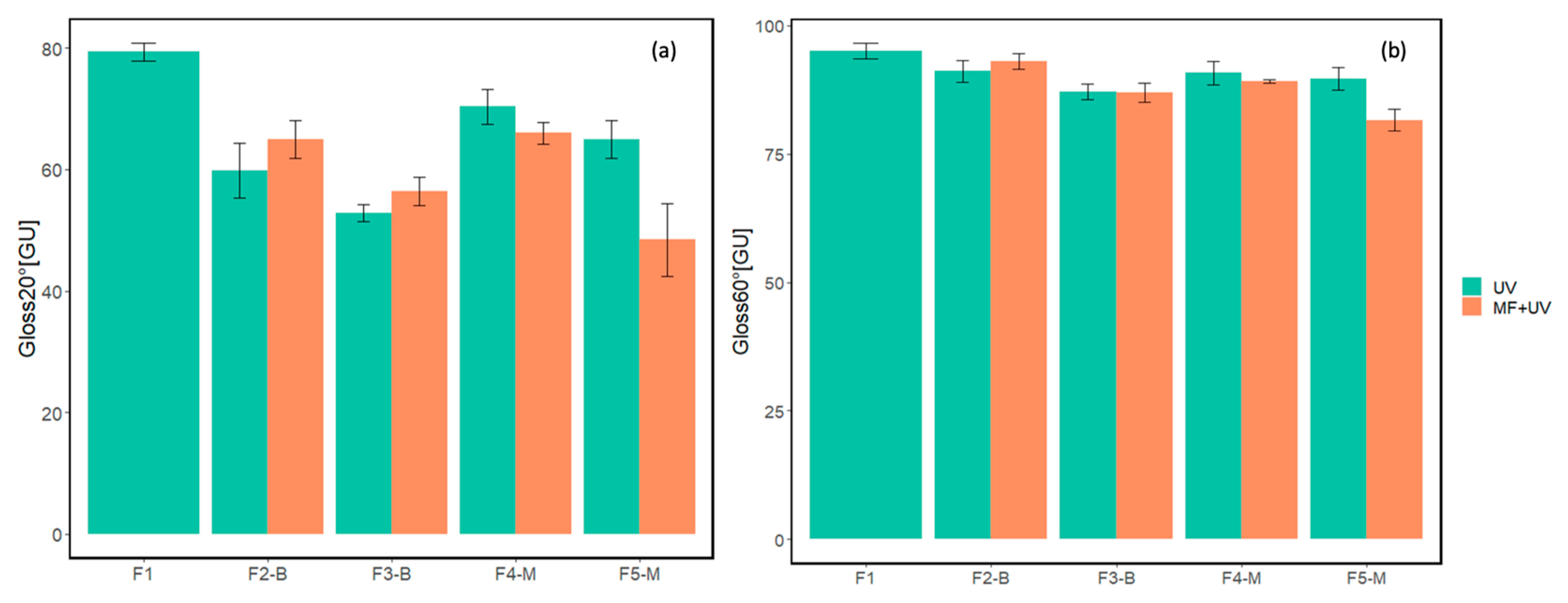
Gloss values at 20° and 60° for five cured formulations are presented in Figure 15. For each formulation, except for reference F1, the left column represents the gloss value for the UV-cured sample without a magnetic field, while the right one shows the gloss value for the UV-MF sample cured under a magnetic field of approximately 60 mT.
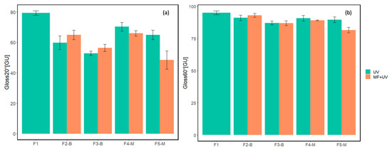
Figure 15.
Results of gloss measurements at (a) 20° and (b) 60° for samples cured with the absence/presence of magnetic field.
Figure 15 demonstrates that as the concentration of MPs increased, the 20° gloss values decreased for both CI and CI-APTES samples compared to the reference F1. This effect is due to the higher light scattering caused by the elevated presence of MPs at the film surface, acting as light scatterers [19,48]. In addition, at equal MP concentrations, CI samples cured under the magnetic field presented a higher 20° gloss than the films cured without MF. However, curing the CI-APTES samples under the magnetic field reduced the 20° gloss. Indeed, the addition of 3%wt of the MPs (F4-M at 60 mT) led to a 15% reduction in the gloss compared to the reference (F1). The modification of the MP played a more significant role at higher concentrations, as in the presence of MF, the highest decrease in the gloss can be observed for F5-M with a 48% reduction at 60 mT. These results align with the surface roughness variations presented in Figure 13.
When measuring the gloss of cured samples at both 20° and 60° angles, it was observed that the 60° measurements consistently showed higher gloss values. Additionally, the variation in gloss values between samples with or without a magnetic field was lower in the 60° measurements.
4. Conclusions
The main aim of this study was to assess how incorporating magnetic particles made of untreated carbonyl iron (CI) and modified CI (CI-APTES) at low addition percentages (3 and 5 wt.%), along with different magnetic field intensities, changes the structure of UV-cured coatings. Furthermore, this study explores how magnetic field and particle concentration changes impact a cured film’s surface roughness and gloss. The results demonstrated that for the CI samples cured without a magnetic field, the MPs were more aggregated and had an elevated presence at the film surface. Higher attraction between the CI particles is believed to be responsible for that effect. Modifying the MPs with APTES reduces the attraction between the particles. Hence, the particles’ dispersion in the film volume is improved, resulting in less aggregation and a lower presence of MPs at the surface. Therefore, CI-APTES films cured without a magnetic field were found to have lower surface roughness. Furthermore, our data also show that the higher the particle concentration, the rougher the surface of the UV-cured coating, both in CI and CI-APTES samples. In addition, the results showed that curing under the magnetic field had the same effects on the CI and the CI-APTES samples. However, depending on the starting point, the change in roughness and gloss was different. Curing the CI samples under a magnetic field led to lower surface roughness and higher gloss by breaking the aggregated particles, redistributing surface MPs, and reconfiguring them as vertical particle chains. For the CI-APTES samples, applying the magnetic field during curing helped the well-distributed MPs within the film volume reconfigure as particle chains and contributed to surface roughness creation. Among the tested formulations, the CI-APTES 5% wt. sample cured under a 60 mT magnetic field showed the highest decrease in 20° gloss. The results obtained from this study have paved the way for the development of low-gloss coatings, demonstrating the feasibility of manipulating surface roughness using low percentages of magnetic particles (MPs) and magnetic fields. Further studies could focus on improving the formulation composition as well as the investigation of the impact of higher-intensity magnetic fields to achieve a lower gloss level.
Supplementary Materials
The following supporting information can be downloaded at: https://www.mdpi.com/article/10.3390/coatings13091625/s1. Figure S1: F3-B sample (5 wt.% CI) cured under UV at 60 mT by using optical microscopy cross-section. Scale bar represents 5 μm. Figure S2: F5-M sample (5 wt.% CI-APTES) cured under UV at 60 mT by using optical microscopy cross-section. Scale bar represents 5 μm.
Author Contributions
Conceptualization, S.D., M.M., and V.L.; methodology, S.D., M.M., and V.L.; software, S.D.; validation, S.D., M.M., I.C., A.H., and V.L.; formal analysis, S.D.; investigation, S.D.; resources, S.D., M.M., and V.L.; data curation, S.D.; writing—original draft preparation, S.D.; writing—review and editing, S.D., M.M., I.C., A.H., and V.L.; visualization, S.D., M.M., and V.L.; supervision, M.M. and V.L; project administration, V.L.; funding acquisition, V.L. All authors have read and agreed to the published version of the manuscript.
Funding
This work was supported by the Natural Sciences and Engineering Research Council of Canada (NSERC) through the IRC program (grant no. RGPIN-2019-06883).
Institutional Review Board Statement
Not applicable.
Informed Consent Statement
Not applicable.
Data Availability Statement
The data presented in this study are available on request from the corresponding author.
Acknowledgments
The authors would like to thank the industrial partners NSERC-Canlak Industrial Research Chair in Interior Wood Product Finishes: Canlak and EMCO-Inortech. Carrying out the experiments and lab tests would not have been possible without the help of lab technicians Yves Bédard, Jean Ouellet, and Félix Pedneault, who shared their knowledge and offered great support for preparing the experimental configurations.
Conflicts of Interest
The authors declare no conflict of interest.
References
- Schwalm, R. UV Coatings: Basics, Recent Developments and New Applications; Elsevier Science: Amsterdam, The Netherlands, 2006. [Google Scholar] [CrossRef]
- Rawat, R.S.; Chouhan, N.; Talwar, M.; Diwan, R.K.; Tyagi, A.K. UV coatings for wooden surfaces. Prog. Org. Coat. 2019, 135, 490. [Google Scholar] [CrossRef]
- Bongiovanni, R.; Montefusco, F.; Priola, A.; Macchioni, N.; Lazzeri, S.; Sozzi, L.; Ameduri, B. High performance UV-cured coatings for wood protection. Prog. Org. Coat. 2002, 45, 359. [Google Scholar] [CrossRef]
- Javadi, A.; Mehr, H.S.; Sobani, M.; Soucek, M.D. Cure-on-command technology: A review of the current state of the art. Prog. Org. Coat. 2016, 100, 2–31. [Google Scholar] [CrossRef]
- Kiyoi, E. Keep it cool to keep it clean. Eur. Coat. J. 2013, 10, 26. [Google Scholar]
- Marshall, A.M.; Fields, J.L. Case Studies: Low-VOC/HAP Wood Furniture Coatings; US Environmental Protection Agency, Office of Research and Development: Research Triangle Park, NC, USA, 2000.
- Dvorchak, M.; Henderson, K.; Gambino, C. New 100% Solids, Acrylated Allophanate Oligomers Offer Low Viscosity and High Functionality while Maximizing UV Coating System Performance. In RadTech Report. 2010. Available online: https://www.radtech.org/proceedings/2010/papers/1529.pdf (accessed on 10 September 2023).
- Bauer, F.; Decker, U.; Czihal, K.; Mehnert, R.; Riedel, C.; Riemschneider, M.; Schubert, R.; Buchmeiser, M.R. UV curing and matting of acrylate nanocomposite coatings by 172 nm excimer irradiation. Prog. Org. Coat. 2009, 64, 474. [Google Scholar] [CrossRef]
- Jones, F.N.; Nichols, M.E.; Pappas, S.P. Organic Coatings: Science and Technology; John Wiley & Sons: Hoboken, NJ, USA, 2017. [Google Scholar]
- Gunde, M.K.; Kunaver, M.; Čekada, M. Surface analysis of matt powder coatings. Dyes Pigments 2007, 74, 74. [Google Scholar] [CrossRef]
- Yong, Q.; Nian, F.; Liao, B.; Guo, Y.; Huang, L.; Wang, L.; Pang, H. Synthesis and surface analysis of self-matt coating based on waterborne polyurethane resin and study on the matt mechanism. Polym. Bull. 2017, 74, 1061. [Google Scholar] [CrossRef]
- Lueers, G.; Kent, D.J.; Petry, V.; Pospesch, U. Matting agent radiation for curing coatings. U.S. Patent No. 6,770,128, 3 August 2004. [Google Scholar]
- Hashemi-Nasab, R.; Mirabedini, S. Effect of silica nanoparticles surface treatment on in situ polymerization of styrene–butyl acrylate latex. Prog. Org. Coat. 2013, 76, 1016. [Google Scholar] [CrossRef]
- Yong, Q.; Chang, J.; Liu, Q.; Jiang, F.; Wei, D.; Li, H. Matt Polyurethane Coating: Correlation of Surface Roughness on Measurement Length and Gloss. Polymers 2020, 12, 326. [Google Scholar] [CrossRef]
- Maskery, S. Development and applications for matting agents. Pigment Resin Technol. 1973, 2, 11–19. [Google Scholar] [CrossRef]
- Landry, V.; Riedl, B.; Blanchet, P. Alumina and zirconia acrylate nanocomposites coatings for wood flooring: Photocalorimetric characterization. Prog. Org. Coat. 2008, 61, 76. [Google Scholar] [CrossRef]
- Yong, Q.; Xu, D.; Liu, Q.; Xiao, Y.; Wei, D. Advances in polymer-based matte coatings: A review. Polym. Adv. Technol. 2022, 33, 5. [Google Scholar] [CrossRef]
- Ou, J.; Zhang, M.; Liu, H.; Zhang, L.; Pang, H. Matting films prepared from waterborne acrylic/micro-SiO2 blends. J. Appl. Polym. Sci. 2015, 132, 41707. [Google Scholar] [CrossRef]
- Yang, Z.; Wu, J.; Ma, G.; Hou, C.; Niu, Y.; Duan, H.; Hao, X. Effect of the particle sizes of silica on the properties of UV-curing matting coatings. J. Coat. Technol. Res. 2021, 18, 183. [Google Scholar] [CrossRef]
- Basu, S.K.; Scriven, L.; Francis, L.; McCormick, A. Mechanism of wrinkle formation in curing coatings. Prog. Org. Coat. 2005, 53, 1. [Google Scholar] [CrossRef]
- Jeong, K.-M.; Park, S.S.; Nagappan, S.; Min, G.; Zhang, Y.; Qu, M.; Zhang, Y.; Ha, C.-S. Highly transparent, organic-inorganic hybrid UV-curable coating materials with amphiphobic characteristics. Prog. Org. Coat. 2019, 134, 323. [Google Scholar] [CrossRef]
- Petry, V.; Kent, D. The effect of UV-curable formulations and matting agents on lacquer properties. Surf. Coat. Int. Part B Coat. Trans. 2004, 87, 103. [Google Scholar] [CrossRef]
- Liu, F.; Liu, A.; Tao, W.; Yang, Y. Preparation of UV curable organic/inorganic hybrid coatings—A review. Prog. Org. Coat. 2020, 145, 105685. [Google Scholar] [CrossRef]
- Rissa, K.; Lepistö, T.; Yrjölä, K. Effect of kaolin content on structure and functional properties of water-based coatings. Prog. Org. Coat. 2006, 55, 137. [Google Scholar] [CrossRef]
- Cho, J.-D.; Kim, Y.-B.; Ju, H.-T.; Hong, J.-W. The effects of silica nanoparticles on the photocuring behaviors of UV-curable polyester acrylate-based coating systems. Macromol. Res. 2005, 13, 362. [Google Scholar] [CrossRef]
- Zhang, H.; Wu, Z. UV-curable self-matting waterborne polyurethane acrylate coating via self-wrinkled surface during curing in open-air. RSC Adv. 2022, 12, 33945. [Google Scholar] [CrossRef]
- Varga, Z.; Filipcsei, G.; Zrínyi, M. Smart composites with controlled anisotropy. Polymer 2005, 46, 7779. [Google Scholar] [CrossRef]
- Chen, L.; Gong, X.; Li, W. Microstructures and viscoelastic properties of anisotropic magnetorheological elastomers. Smart Mater. Struct. 2007, 16, 2645–2649. [Google Scholar] [CrossRef]
- Glavan, G.; Kettl, W.; Brunhuber, A.; Shamonin, M.; Drevenšek-Olenik, I. Effect of Material Composition on Tunable Surface Roughness of Magnetoactive Elastomers. Polymers 2019, 11, 594. [Google Scholar] [CrossRef] [PubMed]
- Glavan, G.; Salamon, P.; Belyaeva, I.A.; Shamonin, M.; Drevenšek-Olenik, I. Tunable surface roughness and wettability of a soft magnetoactive elastomer. J. Appl. Polym. Sci. 2018, 135, 135. [Google Scholar] [CrossRef]
- Li, R.; Li, X.; Yang, P.-A.; Liu, J.; Chen, S. The field-dependent surface roughness of magnetorheological elastomer: Numerical simulation and experimental verification. Smart Mater. Struct. 2019, 28, 085018. [Google Scholar] [CrossRef]
- Dodi, G.; Hritcu, D.; Draganescu, D.; Popa, M.I. Iron oxide nanoparticles for magnetically assisted patterned coatings. J. Magn. Magn. Mater. 2015, 388, 49. [Google Scholar] [CrossRef]
- Samanta, A.; Bordes, R. On the effect of particle surface chemistry in film stratification and morphology regulation. Soft Matter 2020, 16, 6371. [Google Scholar] [CrossRef] [PubMed]
- Lauter-Pasyuk, V.; Lauter, H.; Gordeev, G.; Müller-Buschbaum, P.; Toperverg, B.; Petry, W.; Jernenkov, M.; Petrenko, A.; Aksenov, V. Parallel and perpendicular lamellar phases in copolymer–nanoparticle multilayer structures. Phys. B Condens. Matter 2004, 350, E939. [Google Scholar] [CrossRef]
- Jiang, C.; Ng, S.M.; Leung, C.W.; Pong, P.W. Magnetically assembled iron oxide nanoparticle coatings and their integration with pseudo-spin-valve thin films. J. Mater. Chem. C 2017, 5, 252. [Google Scholar] [CrossRef]
- Filipcsei, G.; Csetneki, I.; Szilágyi, A.; Zrínyi, M. Magnetic Field-Responsive Smart Polymer Composites. Oligomers Polym. Compos. Mol. Imprinting 2007, 206, 137. [Google Scholar] [CrossRef]
- An, J.S.; Kwon, S.H.; Choi, H.J.; Jung, J.H.; Kim, Y.G. Modified silane-coated carbonyl iron/natural rubber composite elastomer and its magnetorheological performance. Compos. Struct. 2017, 160, 1020. [Google Scholar] [CrossRef]
- Ronzova, A.; Sedlacik, M.; Cvek, M. Magnetorheological fluids based on core–shell carbonyl iron particles modified by various organosilanes: Synthesis, stability and performance. Soft Matter 2021, 17, 1299. [Google Scholar] [CrossRef] [PubMed]
- Noval, V.E.; Carriazo, J.G. Fe3O4-TiO2 and Fe3O4-SiO2 Core-shell Powders Synthesized from Industrially Processed Magnetite (Fe3O4) Microparticles. Mater. Res. 2019, 22, 1. [Google Scholar] [CrossRef]
- Yang, H.; Li, S.; Wang, X.; Zhang, F.; Zhong, X.; Dong, Z.; Ma, J. Core–shell silica magnetic microspheres supported proline as a recyclable organocatalyst for the asymmetric aldol reaction. J. Mol. Catal. A Chem. 2012, 363, 404. [Google Scholar] [CrossRef]
- Hermann, A.; Burr, D.; Landry, V. Comparative study of the impact of additives against oxygen inhibition on pendulum hardness and abrasion resistance for UV-curable wood finishes. Prog. Org. Coat. 2020, 148, 105879. [Google Scholar] [CrossRef]
- Yoon, T.H.; Lee, Y.K.; Lim, B.S.; Kim, C.W. Degree of polymerization of resin composites by different light sources. J. Oral Rehabil. 2002, 29, 1165. [Google Scholar] [CrossRef]
- Nguyen, T.V.; Nguyen-Tri, P.; Azizi, S.; Dang, T.C.; Hoang, D.M.; Hoang, T.H.; Nguyen, T.L.; Le Bui, T.T.; Dang, V.H.; Nguyen, N.L. The role of organic and inorganic UV-absorbents on photopolymerization and mechanical properties of acrylate-urethane coating. Mater. Today Commun. 2020, 22, 100780. [Google Scholar] [CrossRef]
- Nagarajan, B.; Wang, Y.; Taheri, M.; Trudel, S.; Bryant, S.; Qureshi, A.J.; Mertiny, P. Development and Characterization of Field Structured Magnetic Composites. Polymers 2021, 13, 2843. [Google Scholar] [CrossRef]
- Tyson, B.M.; Al-Rub, R.K.A.; Yazdanbakhsh, A.; Grasley, Z. A quantitative method for analyzing the dispersion and agglomeration of nano-particles in composite materials. Compos. Part B Eng. 2011, 42, 1395. [Google Scholar] [CrossRef]
- Luo, Z.; Koo, J.H. Quantifying the dispersion of mixture microstructures. J. Microsc. 2007, 225, 118. [Google Scholar] [CrossRef]
- Järnström, J.; Ihalainen, P.; Backfolk, K.; Peltonen, J. Roughness of pigment coatings and its influence on gloss. Appl. Surf. Sci. 2008, 254. [Google Scholar] [CrossRef]
- Fletcher, T. A simple model to describe relationships between gloss behaviour, matting agent concentration and the rheology of matted paints and coatings. Prog. Org. Coat. 2002, 44, 25–36. [Google Scholar] [CrossRef]
- Calvez, I.; Szczepanski, C.R.; Landry, V. Preparation and characterization of low gloss UV-curable coatings based on silica surface modification using an acrylate monomer. Prog. Org. Coat. 2021, 158, 106369. [Google Scholar] [CrossRef]
- Wu, J.; Gong, X.; Chen, L.; Xia, H.; Hu, Z. Preparation and characterization of isotropic polyurethane magnetorheological elastomer through in situ polymerization. J. Appl. Polym. Sci. 2009, 114, 901. [Google Scholar] [CrossRef]
- Cvek, M.; Mrlik, M.; Ilcikova, M.; Plachy, T.; Sedlacik, M.; Mosnacek, J.; Pavlinek, V. A facile controllable coating of carbonyl iron particles with poly(glycidyl methacrylate): A tool for adjusting MR response and stability properties. J. Mater. Chem. C 2015, 3, 4646. [Google Scholar] [CrossRef]
- Jun, J.-B.; Uhm, S.-Y.; Ryu, J.-H.; Suh, K.-D. Synthesis and characterization of monodisperse magnetic composite particles for magnetorheological fluid materials. Colloids Surf. A Physicochem. Eng. Asp. 2005, 260, 157. [Google Scholar] [CrossRef]
- Wu, J.; Xie, J.; Ling, L.; Ma, G.; Wang, B. Surface modification of nanosilica with 3-mercaptopropyl trimethoxysilane and investigation of its effect on the properties of UV curable coatings. J. Coat. Technol. Res. 2013, 10, 849–857. [Google Scholar] [CrossRef]
- Landry, V.; Riedl, B.; Blanchet, P. Nanoclay dispersion effects on UV coatings curing. Prog. Org. Coat. 2008, 62, 400. [Google Scholar] [CrossRef]
- Pickering, K.L.; Khimi, S.R.; Ilanko, S. The effect of silane coupling agent on iron sand for use in magnetorheological elastomers Part 1: Surface chemical modification and characterization. Compos. Part A Appl. Sci. Manuf. 2015, 68, 377. [Google Scholar] [CrossRef]
- Mehdizadeh, A.; Mei, R.; Klausner, J.F.; Rahmatian, N. Interaction forces between soft magnetic particles in uniform and non-uniform magnetic fields. Acta Mech. Sin. 2010, 26, 921. [Google Scholar] [CrossRef]
- Krommenhoek, P.J.; Tracy, J.B. Magnetic Field-Directed Self-Assembly of Magnetic Nanoparticle Chains in Bulk Polymers. Part. Part. Syst. Charact. 2013, 30, 759. [Google Scholar] [CrossRef]
- Li, R.; Li, X.; Li, Y.; Yang, P.-A.; Liu, J. Experimental and numerical study on surface roughness of magnetorheological elastomer for controllable friction. Friction 2020, 8, 917–929. [Google Scholar] [CrossRef]
- Zablotskii, V.; Lunov, O.; Kubinova, S.; Polyakova, T.; Sykova, E.; Dejneka, A. Effects of high-gradient magnetic fields on living cell machinery. J. Phys. D Appl. Phys. 2016, 49, 493003. [Google Scholar] [CrossRef]
- Shiwei, C.; Shuai, D.; Xiaojie, W.; Weihua, L. Magneto-induced surface morphologies in magnetorheological elastomer films: An analytical study. Smart Mater. Struct. 2019, 28, 045016. [Google Scholar] [CrossRef]


Disclaimer/Publisher’s Note: The statements, opinions and data contained in all publications are solely those of the individual author(s) and contributor(s) and not of MDPI and/or the editor(s). MDPI and/or the editor(s) disclaim responsibility for any injury to people or property resulting from any ideas, methods, instructions or products referred to in the content. |
© 2023 by the authors. Licensee MDPI, Basel, Switzerland. This article is an open access article distributed under the terms and conditions of the Creative Commons Attribution (CC BY) license (https://creativecommons.org/licenses/by/4.0/).