Abstract
A polyurethane/Laponite/graphene transparent coating with high surface hardness, obtained by dispersing the Laponite–graphene oxide (Lap-GO) in polyurethane for UV reduction, is reported. Lap-GO improves the hardness of the coating, where Laponite is intercalated between graphene layers through electrostatic action, preventing the re-accumulation or aggregation of graphene and ensuring the transparency of the coating. The analysis of pencil hardness and light transmittance shows that when the Lap-GO content is 0.05 wt‰ and the UV reduction is 10 min, the hardness of the coated pencil increases to 5H, and the light transmittance remains above 85%. Furthermore, the polyurethane/Laponite/graphene transparent coating also has excellent cold liquid resistance and meets specific usage standards. The prepared polyurethane/Laponite/graphene transparent coatings are promising for broad application prospects in cover and protective coatings.
1. Introduction
Polyurethane is widely used in various industries due to its unique chain segment structure, flexible formula, and simple processing, including as flame-retardant materials in the construction industry, anti-corrosion coatings for metal materials, adhesives for furniture, etc. [1,2,3]. Compared with traditional solvent-based polyurethane, waterborne polyurethane is widely used on the surface of wood, furniture, and automotive parts because of its low VOCs, green environmental protection, and good moisture permeability [4,5,6,7,8,9]. Coatings are generally used as thin films that protect or decorate the surface of objects, and their hardness reflects the ability of coatings to resist physical damage such as scratches, squeezing, and other effects caused by external objects [10,11]. However, polyurethane has a lower hardness after curing, which can easily cause scratches on its surface due to squeezing and scratching, which can seriously affect the aesthetics and the protective performance of the coating [12,13]. Therefore, it is necessary to find a method to improve the scratch resistance of polyurethane transparent coatings without affecting the aesthetics and visibility thereof.
Nanomaterials are widely considered a promising filler to improve the performance of polymers because of their small size effect and good surface effect [14,15]. Graphene, a planar single-layer carbon nanomaterial with a two-dimensional honeycomb structure [16,17], has excellent properties, such as high Young’s modulus [18], tensile strength [19], structural flexibility [20], highly adjustable optical properties [21], etc. Its derivative, graphene oxide (GO), can directly react with isocyanate without modification. Xu et al. [10] dispersed GO into waterborne polyurethane using a physical mixing method, and the addition of GO effectively improved the water resistance, alcohol resistance, and mechanical properties of the coating. At the same time, the paint film they developed is superior to commercially available coatings in terms of glossiness, wear resistance, hardness, etc. Li et al. [22] have shown that graphene can enhance the corrosion resistance of waterborne polyurethane coatings, and a 0.4 wt% graphene content waterborne polyurethane composite coating has good corrosion resistance. Laponite, as an artificially synthesized two-dimensional layered hectorite, has a high size matching with the hard segment size of polyurethane, and its transparent dispersion has unique rheological and conductive properties, making it widely used for modifying polyurethane [23,24,25]. Choi et al. [26] added modified clay to the polyurethane main chain and prepared waterborne polyurethane/nano clay composite coatings using UV curing. The results showed that the modified clay significantly improved the polyurethane coating’s hardness, thermal stability, and barrier properties. Rahman et al. [27] prepared waterborne polyurethane/nano clay composite materials using a pre-polymerization method to enhance the coating’s water resistance, heat resistance, and other properties. The tensile strength of the composite film was the highest when the clay content was 1 wt%. Both graphene and nano-clay have achieved good improvement in the properties of polyurethane-modified materials, but there is little research on polyurethane modification using these two materials.
Due to the π–π force between graphene sheets, they are prone to re-stacking and agglomeration [28], while the oxygen-containing functional groups between oxidized graphene sheets make them easy to modify. J Ming et al. [29] used p-Methyl styrene groups covalently grafted onto graphene oxide (GO) via esterification reactions. T Furkan et al. [30] used two different monomers, namely hexafluoro butyl acrylate (HFBA) and diethyl aminoethyl methacrylate (DEAEMA), individually to modify graphene oxide (GO) nanosheets via the environmentally friendly plasma-enhanced chemical vapor deposition (PECVD) method. Laponite (with molecular formula Na+0.7 [(Si8Mg5.5Li0.3) O20(OH)4]0.7−) is a synthetic hectorite clay with disc-shaped particles that are similar in size to the hard segments of polyurethane (mean diameter of 30 nm and thickness 1 nm) [31]. Meanwhile, studies have shown that a series of nano clay materials such as Laponite are widely used to assist the dispersion of graphene and GO in the matrix [32]. GO and Laponite have excellent water dispersion, and the composite of GO and Laponite with waterborne polyurethane coatings is conducive to uniform dispersion of nanomaterials.
Therefore, this study used graphene and Laponite to modify polyurethane, and the effect of graphene agglomeration on the transparency of the coating was reduced as much as possible while the hardness of the coating was greatly improved. The Lap-GO/polyurethane composite coating was obtained by combining GO and Laponite with waterborne polyurethane coatings at the same time, and a new Laponite/graphene polyurethane transparent coating with high surface hardness was obtained by UV reduction. The interlayer Na+ ions are likely to have electrostatic interaction with the electron-rich oxygen-containing groups [33] when inserting Laponite between GO layers to improve the dispersion of graphene in the matrix. During the curing process, the oxygen-containing functional groups on the GO surface react chemically with diisocyanate and polyether polyol in WPU, thus forming a cross-linked network containing Lap-GO [34]. Moreover, Laponite intercalates in the polyurethane hard segment and plays a hardening role [23]. The optimal ratio of Laponite to GO and the effect of Lap-GO addition on the hardness and transparency of the coating were studied. In addition, the water and alcohol resistance of polyurethane was evaluated to expand its application in transparent protective coatings.
2. Material and Methods
2.1. Materials
Graphite powder (8000 mesh) was purchased from Kiana Graphene Technology Co., Ltd. (Xiamen, China). Potassium permanganate (KMnO4), hydrogen peroxide (H2O2, 30%), concentrated sulfuric acid (H2SO4), and anhydrous ethanol (C2H6O, 98%) were all supplied by Sino phosphoric Chemical Reagent Co., Ltd. (Dalian, China). Laponite RD (BATCH I.D. 20-4021) (Laponite) with a chemical composition of SiO2 59.5%, MgO 27.5%, Li2O 0.8%, and Na2O 2.8 and a loss on ignition of 8.2% was supplied by BYK Additives & Instruments (Wesel, Germany). Waterborne polyurethane coating was purchased from Minghui Paint Factory (Taizhou, China) and it was synthesized by reacting methyl diphenyl diisocyanate (MDI) and polyester polyol. Ultrapure water was made in the laboratory. Without a particular description, all materials were analytically pure and were used directly without further purification.
2.2. Preparation of Lap-GO Dispersion
GO was prepared by Hummers’ method: Typically, graphite powder (2.0 g) was added to concentrated H2SO4 (100 mL) under stirring in an ice water bath. Under vigorous agitation, KMnO4 (12 g) was slowly added to the solution and stirred in an ice water bath for 30 min. The reaction system was successfully transferred to a medium temperature water bath environment (about 45 °C) and stirred for about 2 h. Then, 100 mL of ultrapure water was added and the solution temperature was maintained below 95 °C until it dropped to room temperature. Subsequently, 10 mL H2O2 (30%) was added to the solution to form a golden yellow viscous liquid. Finally, the graphene oxide was obtained by centrifugation and cold drying.
Laponite (1 g) was thoroughly mixed in 100 mL ultrapure water and stirred consistently for 30 min at room temperature. Subsequently, GO was added to the above Laponite dispersion in different mass ratios. Finally, dispersion with mass ratios of 10:1, 10:2, 10:4 to 10:10 (Laponite:GO) was completed. The black powder obtained by freeze-drying was denoted as Lap-GO.
2.3. Preparation of Polyurethane Nanocomposite Solution
First, the Lap-GO aqueous solution was subjected to 10 min of high-frequency ultrasound to obtain Lap-GO dispersion with concentrations of 1.00 wt% and 0.10 wt%, respectively. Then, Lap-GO dispersions were added to the purchased single-component waterborne polyurethane coating under high-speed dispersion, resulting in polyurethane nanocomposite solutions with Lap-GO contents of 0.05 wt‰, 0.10 wt‰, 0.50 wt‰, and 1.00 wt‰. The numbering and Lap-GO content of the composite solution are shown in Table 1.

Table 1.
Sample and Lap-GO content of Lap-GO/polyurethane composite solution.
2.4. Preparation of Polyurethane/Laponite/Graphene Transparent Coatings with High Surface Hardness
A polyurethane/Laponite/graphene coating was prepared according to the Chinese national standard GB/T 9271-2008 [35]. Typically, this involves polishing the tinplate with sandpaper to remove the grease on its surface and adding polyurethane composite solution to the tinplate to prepare the Lap-GO/polyurethane composite coating with uniform thickness through the automatic coating mechanism. The prepared coating was cured at room temperature for 7 days. Finally, ultraviolet light was used to irradiate the coating to obtain the Laponite/graphene/polyurethane transparent coating with a high surface hardness.
The prepared solution was poured into the customized mold and cured at room temperature for 3 days to obtain Lap-GO/polyurethane composite coating with a thickness of 0.3 mm, which was then reduced by UV lamps to obtain a Laponite/graphene/polyurethane transparent coating with a high surface hardness for the subsequent light transmittivity test.
2.5. Test Characterization Methods
The structure of GO, Lap-GO, and Laponite powders was characterized using X-ray diffraction (XRD, manufactured by Rigaku, sourced from Tokyo, Japan) with a Cu Kα radiation at 40 kV and 40 mA and a scanning rate of 10°/min. The Dimension ICON Atomic force microscope (AFM, Bruker, Madrid, Spain) was used for Lap-GO lamellar spacing testing; The morphology of fracture surfaces of the WPU matrix coatings was examined by field-emission scanning electron microscope (FESEM, manufactured by HITACHI, sourced from Tokyo, Japan) with the operating voltage and the operating current at 5 kV and 10 mA, respectively; the film samples were subjected to gold spraying after liquid nitrogen embrittlement. A transmission electron microscope (TEM, FEI/Talos F200X G2, manufactured by Thermo scientific, sourced from Waltham, MA, USA) was used to evaluate the nanoscopic dispersion states of Lap-GO in the WPU matrix at an acceleration voltage of 300 kV. The surface chemistry of GO and Lap-GO was characterized using Fourier transfer infrared spectrometry (FTIR, Nicolet Is 50 Fourier, manufactured by Thermo Fisher Scientific, sourced from Waltham, MA, USA). FT-IR spectra were collected in attenuated total reflection mode for the wavenumber range 4000–400 cm−1 at a resolution of 0.4 cm−1.
The transmittance of the composite coating was tested using the Evolution201 UV-VIS spectrophotometer (manufactured by Thermo Fisher Scientific, sourced from Waltham, MA, USA) with a test range of 200–800 nm. According to the Chinese national standard GB/T 6739-2006 [36], the pencil hardness of the composite coating was tested using a BEVS 1301 pencil hardness tester. According to the Chinese national standard GB/T 30693-2014 [37], the water contact angle (WCA) of the coating was tested using the JC2000D6 contact angle measuring instrument. According to the Chinese national standard GB/T 4893.1-2021 [38], the water resistance and alcohol resistance of the coating were tested with ultrapure water and 75 wt% ethanol at room temperature.
3. Results and Discussion
3.1. XRD Analysis of Lap-GO Dispersion
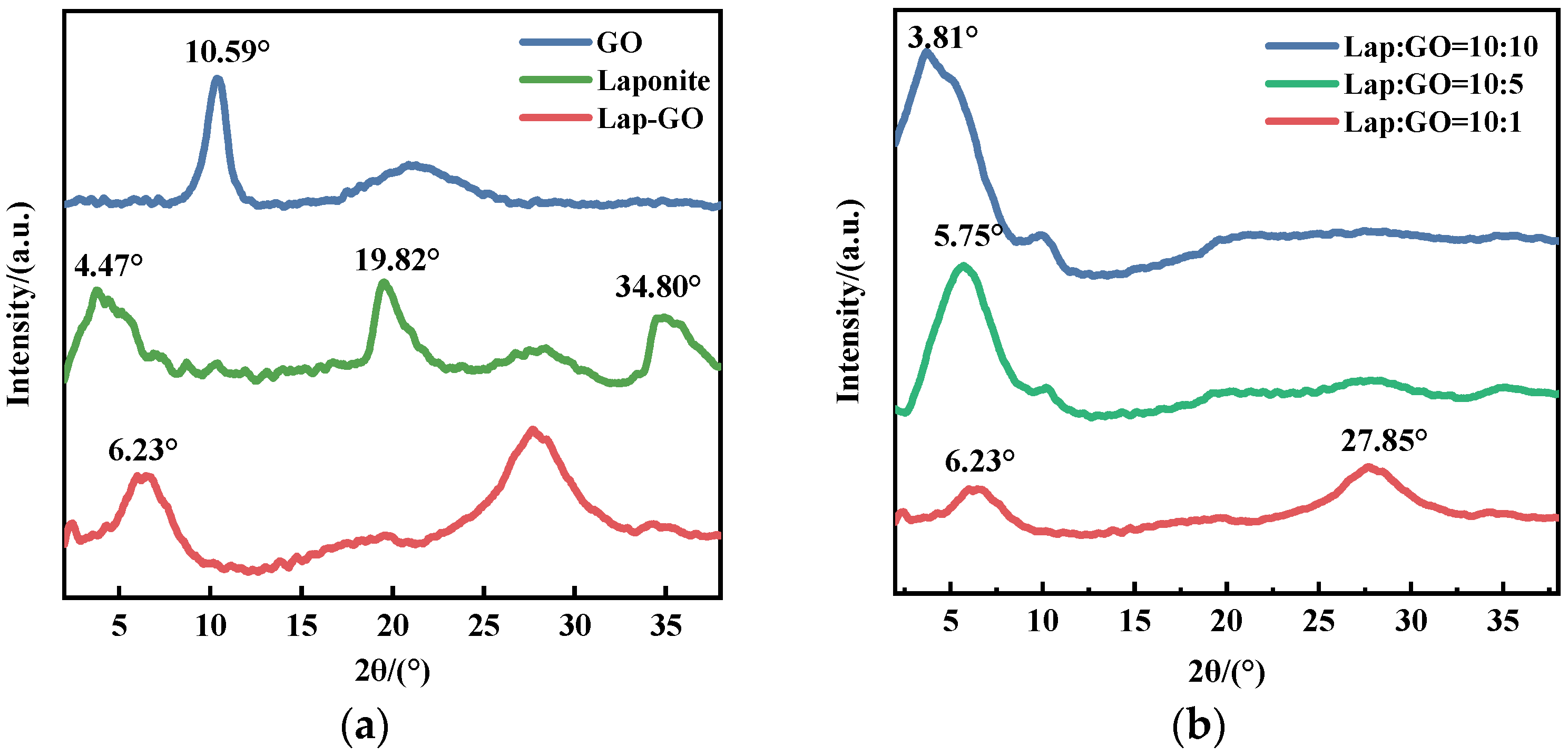
The XRD patterns of Lap-GO, GO, and Laponite powder are shown in Figure 1a. A broad diffraction peak of the Laponite (001) crystal face is reflected at 2θ = 4.47°, and the diffraction peak of GO is reflected at 2θ = 10.48°. The (001) crystal plane diffraction peak of Lap-GO is at 2θ = 6.23°, which is closer to the Laponite (001) crystal plane diffraction peak, and the (001) crystal plane diffraction peak of GO may also shift to 2θ = 6.23°. From the above observations, it is apparent that the layer structure of GO has been disrupted, leading to the layer recombination between GO and Laponite, and there may be intercalation between GO and Laponite [33].
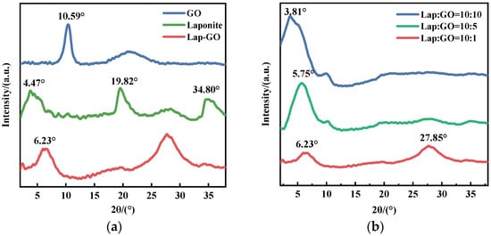
Figure 1.
(a) XRD pattern of Lap-GO dispersion; (b) XRD patterns of Lap-GO dispersions with different mass ratios.
Meanwhile, XRD tests were conducted on Lap-GO dispersions with mass ratios of 10:1, 10:5, and 10:10, and the data are shown in Figure 1b. With the Lap/GO ratio increase, the diffraction peak of the crystal face of the Lap-GO dispersion (001) gradually shifts to the left, suggesting an increased interlayer spacing and a co-stacked structure between Laponite and GO.
3.2. FT-IR Analysis of Lap-GO Dispersion
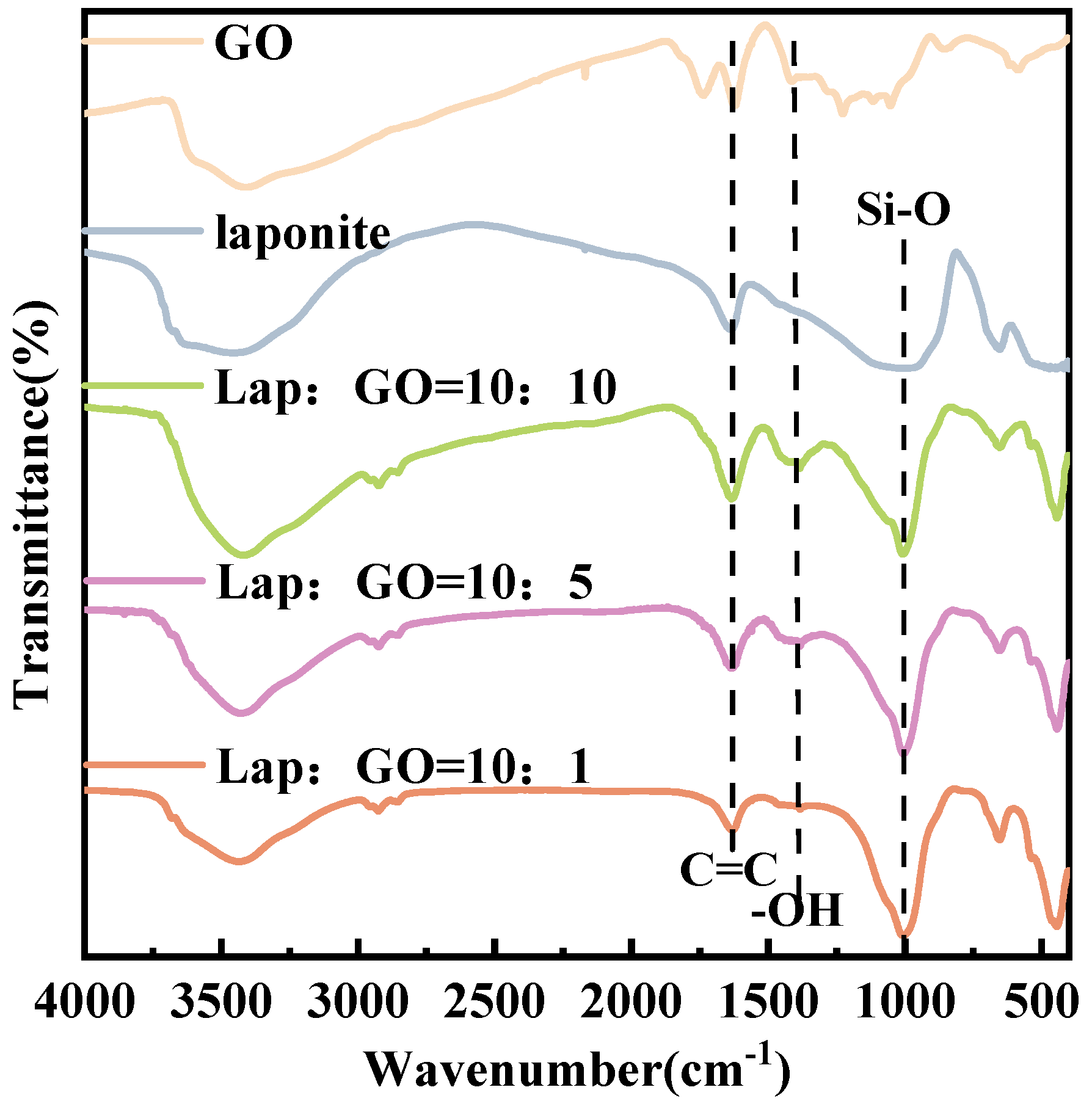
The FT-IR checked the surface groups of GO, Laponite, and Lap-GO samples and the spectra are shown in Figure 2. GO showed very broad peaks ranging from around 3500 cm−1 to 2500 cm−1, corresponding to the -OH stretching vibration. The peaks at 1732 cm−1 belong to the carboxyl C=O group, and the peaks at 1409 cm−1 and 1062 cm−1 correspond to the absorption band of -OH and the absorption peak of the epoxy group stretching vibration in the carbon ring, respectively. After functionalized by Laponite, new absorption peaks appeared at 1000 cm−1, attributed to the Si-O stretching vibrations of the tetrahedron in Laponite [39], and no excess functional groups were generated.
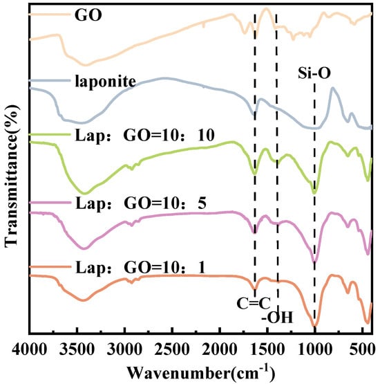
Figure 2.
FT-IR spectra of Lap-GO dispersions with different mass ratios.
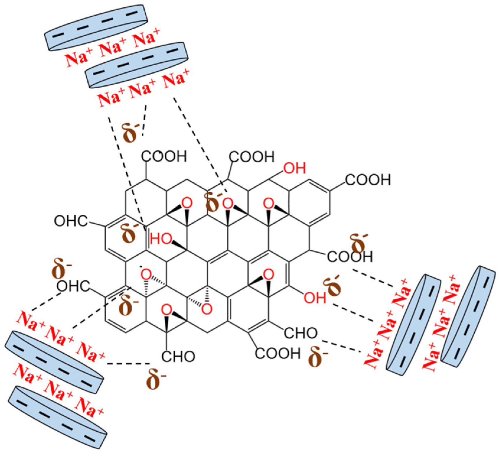
Thus, XRD and FT-IR characterization revealed no significant chemical interaction between Laponite and GO. A holistic appraisal of the results obtained from the above characterization techniques indicated a specific interaction, most likely an electrostatic interaction, between these two components, leading to the formation of a new functional hybrid material. In this case, the formation of Lap-GO dispersion may be due to the Na+ between Laponite layers interacting electrostatically with oxygen-containing functional groups on the GO surface [23], as shown in Figure 3.

Figure 3.
Schematic diagram of electrostatic interaction between Laponite and GO.
3.3. Selection of Mass Ratio of Lap-GO Dispersion
The dispersion of the Lap-GO solution with the different mass ratios of Laponite/GO dispersion immediately after ultrasound and one month after ultrasound are shown in Figure 4a,b. The mass ratios of Laponite/GO in Sample I, Ⅱ, Ⅲ, Ⅳ, and Ⅴ are 10:1, 10:2, 10:4, 10:6, and 10:8, respectively. It is confirmed that with the increase in the specific gravity of GO, the Lap-GO dispersion solution does not easily fall, and its gel is gradually settled.

Figure 4.
Optical photos of Lap-GO dispersions with different mass ratios. (a) Immediately after ultrasound completion; (b) after one month.
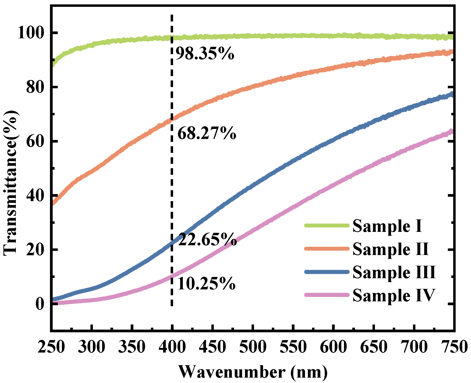
The transmission test results of the three types of Lap-GO dispersions and the Laponite colloidal dispersion are shown in Figure 5. The mass ratios of Laponite/GO in Sample I, Ⅱ, Ⅲ, and Ⅳ are 10:0, 10:1, 10:5, and 10:10, respectively. The Laponite dispersion showed almost 100% transmission ratio, and with the addition of GO, the transmittance of Lap-GO dispersion aqueous solution in the visible light range immediately decreased. At a wavelength of 400 nm, the transmittance of Sample II decreased to 68.27%, Sample III decreased to 22.65%, and Sample IV decreased to 10.25%.
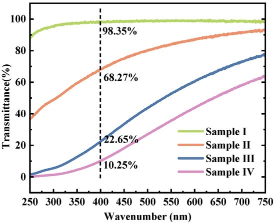
Figure 5.
Transmission spectra of Lap-GO dispersions with different mass ratios. (Ⅰ) Laponite; (Ⅱ) Laponite: GO = 10:1; (Ⅲ) Laponite: GO = 10:5; (Ⅳ) Laponite: GO = 10:10.
The above characterization methods show that with the increase in the specific gravity of GO, the transmission ratio of the obtained Lap-GO dispersion gradually decreases in the visible light range, and the solution gelatinization is settled, making GO difficult to disperse. Therefore, in order to ensure the light transmission of the subsequent test material and the fluidity of the solution as much as possible, the Lap-GO dispersion with a mass ratio of 10:1 of Laponite and GO was selected as the material for subsequent research.
3.4. AFM Analysis of Lap-GO Dispersion
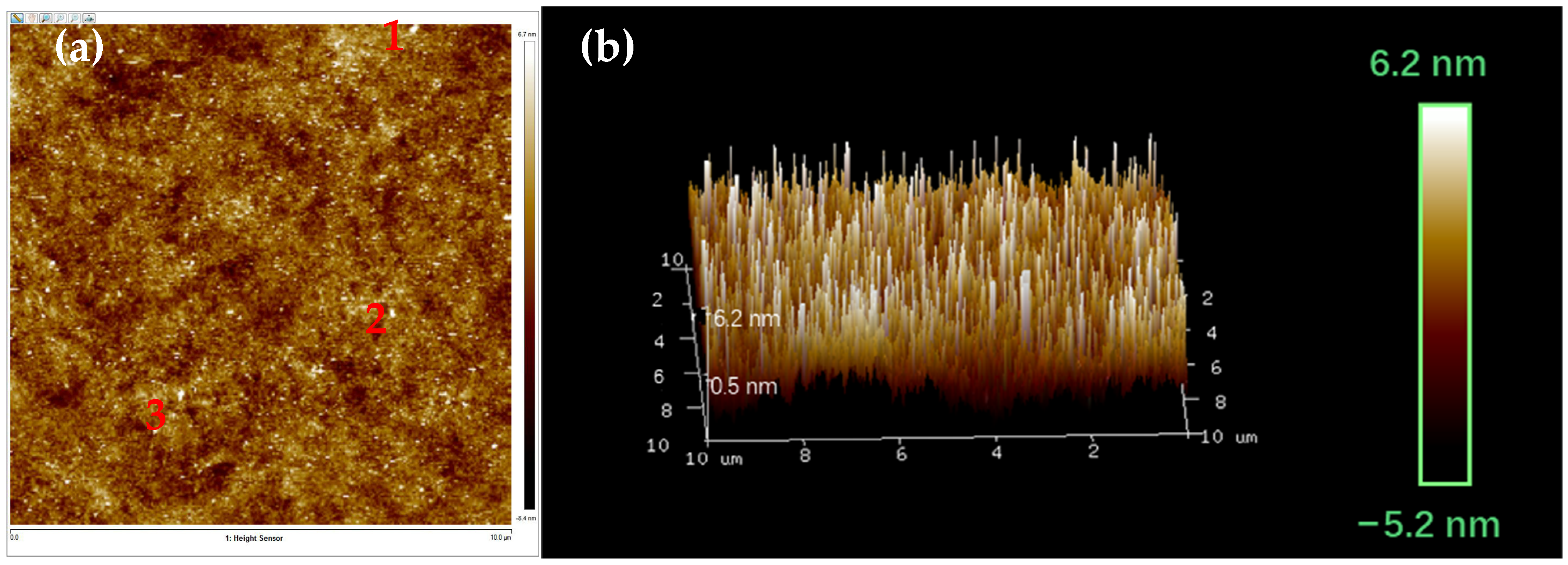
The AFM diagram of the Lap-GO dispersion and its layer thickness after ultrasound are shown in Figure 6. After ultrasonic dispersion, Lap-GO is evenly dispersed and has a uniform layer color with similar thickness, and its shape is an irregular sheet-like structure. In an ideal situation, the thickness of monolayer graphene is 0.34 nm [40]. We selected three representative points (1, 2, and 3) in Figure 6a and confirmed their thickness and slice diameter. The specific data are shown in Table 2. According to AFM data, the thickness of Lap-GO increases compared with the thickness of GO lamella, mainly because the Laponite intercalated in GO increases the thickness of Lap-GO lamella [41], and the Lap-GO dispersion after ultrasound is uniform without agglomeration.

Figure 6.
AFM characterization of Lap-GO dispersion in (a) a two-dimensional image; (b) a 3D image.

Table 2.
AFM two-dimensional image data.
3.5. Analysis of Coating Microstructure
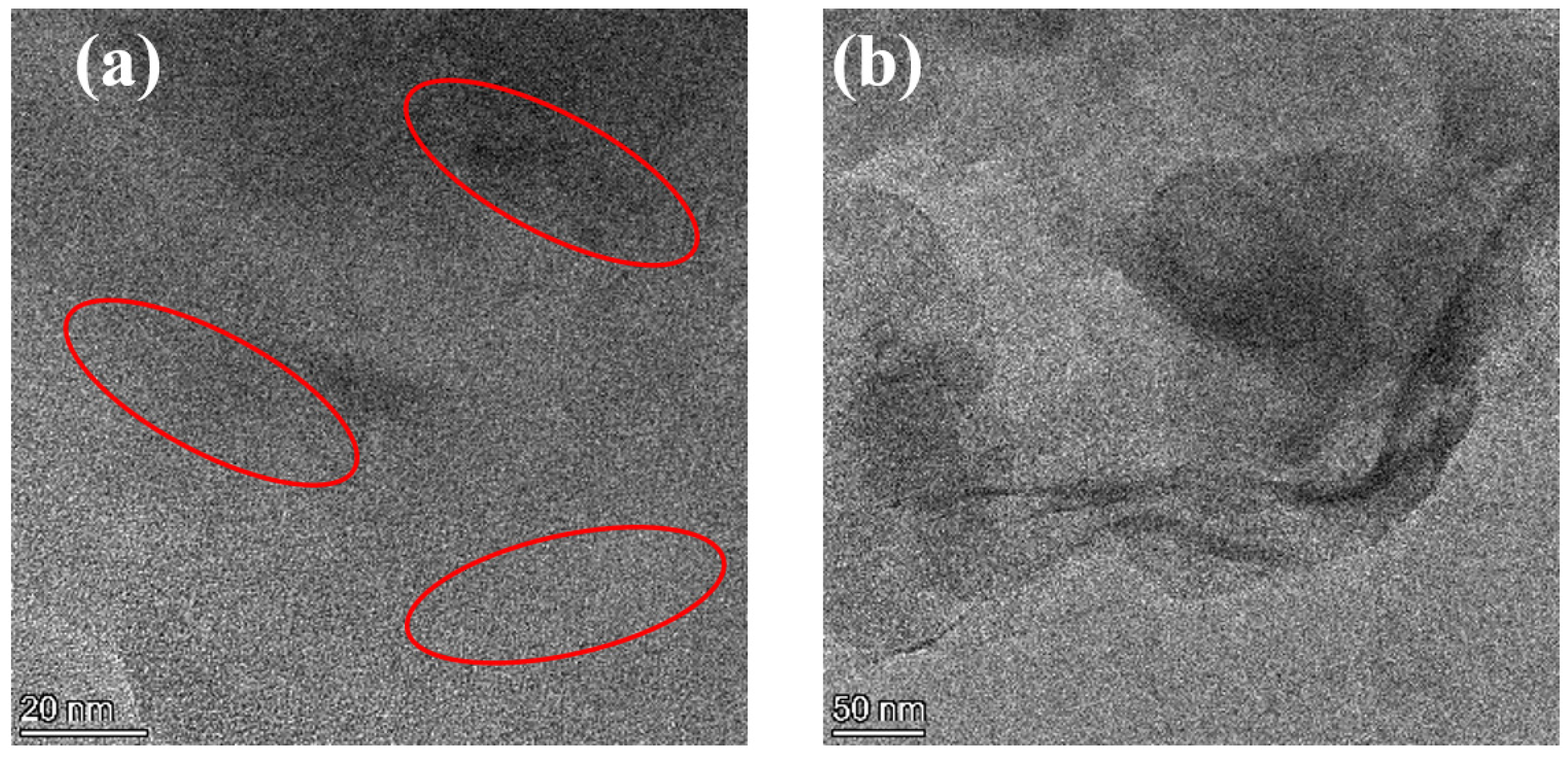
The nanoscopic dispersion of Lap-GO in polyurethane is shown in Figure 7. The dark lines (inside the red circle) represent Lap-GO, while the bright area represents the WPU matrix. For the Lap-GO/polyurethane coatings, the dispersed Lap-GO liner and stacking of multiple layers of material are likely due to Lap-GO dispersed in a layered manner in the polyurethane matrix. In summary, Lap-GO is uniformly dispersed in a few layers in the polyurethane matrix after ultrasonic dispersion.
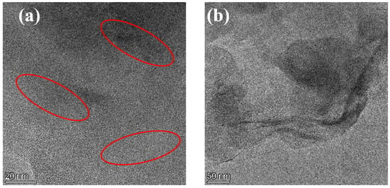
Figure 7.
(a,b) TEM diagram of Lap-GO/polyurethane composite coating.
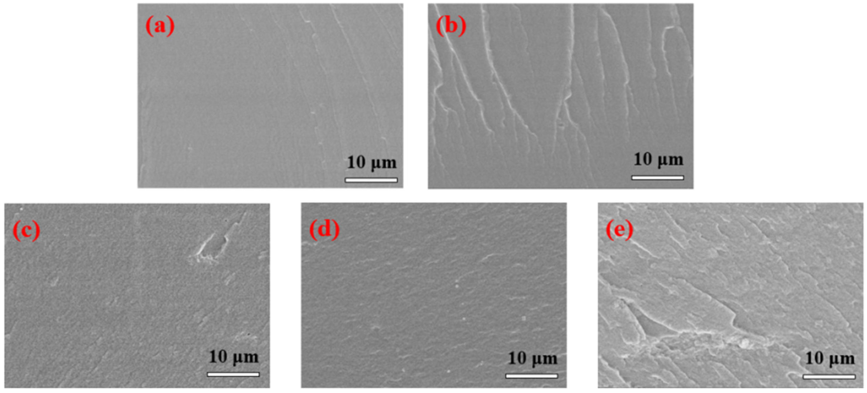
The fracture surfaces of Lap-GO/polyurethane coatings with different Lap-GO content are shown in Figure 8. The pure WPU coatings showed very smooth fracture surfaces in Figure 8a. With the addition of Lap-GO, the fracture surfaces of the composite coatings showed higher roughness than neat WPU (Figure 8b–e), and the content of Lap-GO in composites from (b) to (e) increased successively, but there is no obvious aggregation of fillers. This indicates that Lap-GO has good compatibility with polyurethane matrix, and the material’s microstructure is an important factor determining the material’s physical properties, which is also reflected in the subsequent performance tests of the composite coating [42].
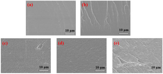
Figure 8.
FESEM diagram of Lap-GO/polyurethane composite coating. (a) PURE; (b) 0.05Lap-GO; (c) 0.1Lap-GO; (d) 0.5Lap-GO; (e) 1Lap-GO.
3.6. Analysis of Coating Hardness
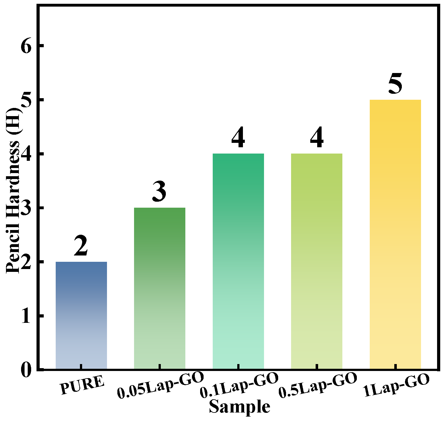
The influence of Lap-GO nanomaterial on the pencil hardness of the polyurethane coating is recorded in Figure 9. From the results, with the addition of Lap-GO, the pencil hardness of the coating increases. For the 1Lap-GO composite coating, the pencil hardness of the composite coating was the highest, and its pencil hardness increased by three orders of magnitude compared to pure polyurethane (PURE). The improvement is attributed to the stress transfer across the interface between Lap-GO and polyurethane due to the Lap-GO cross-linked with polyurethane and residual Laponite intercalated into the polyurethane hard segments.

Figure 9.
Pencil hardness Lap-GO/polyurethane composite coating.
As shown in Figure 10a, during the curing process, the oxygen-containing functional groups on the GO surface react chemically with diisocyanate and polyether polyol in WPU, thus forming a cross-linked network containing Lap-GO, while some Laponite has a strong electrostatic force between it and polyurethane chain segments due to the positive and negative charges on its surface [32]. Moreover, the high matching between Laponite layer diameter and polyurethane hard segment size enables Laponite to better intercalate in the polyurethane hard segment and play a hardening role [33]. After hydrolysis, Laponite has a negative surface charge and a positive edge charge, forming a “card house” structure in an aqueous solution. rGO remains negatively charged due to its surface’s remaining oxygen-containing functional groups [43]. There is electrostatic repulsion between the surface of the Laponite and the GO, and electrostatic attraction between the edges of the two, which allows the Laponite to intercalate between the graphene sheets, preventing the re-accumulation or agglomeration of the graphene [44]. GO, Laponite, Lap-GO, polyurethane (PURE), and 0.05Lap-GO were characterized by infrared, and the results are shown in Figure 10b. In the FT-IR analysis of PURE samples, C-H asymmetric stretching vibration absorption peaks in -CH3 and -CH2 appeared at 2948 cm−1 and 2871 cm−1, while 1536 cm−1 and 1231 cm−1 correspond to C-O stretching vibration peaks in the amido band and acyl group, respectively. In the GO infrared spectrum, the wide absorption peak at 3417 cm−1 is caused by the stretching vibration of hydroxyl groups, and 1732 cm−1 is the absorption band corresponding to C=O in the carboxyl group. The absorption band of -OH bending vibration corresponding to 1409 cm−1 and the absorption peak of the epoxy group stretching vibration in the carbon ring at 1062 cm−1 are the most characteristic peaks of GO in FT-IR spectra. The peaks of about 1000 cm−1 in the Lap-GO dispersion are caused by Si-O vibration of the tetrahedron in the Laponite. For 0.05Lap-GO, the absorption peak of the oxygen-containing functional groups (hydroxyl group, carboxyl group and epoxide group) in the IR spectrum of 0.05Lap-GO was significantly weakened, and the stretching vibration peak of OH at 3324 cm−1 was weakened, indicating that the OH of GO had a chemical reaction with isocyanate in polyurethane. In addition, the stretching vibration peak of C-O-C at about 1100 cm−1 at 0.05Lap-GO was weaker than that of PURE, indicating that some GO reacts with the coating. The peaks at 1000 cm−1 and 1300 cm−1 associated with Laponite coincide with the main characteristic peaks in PU and GO, confirming the mechanism prediction of Lap-GO enhancement of coating hardness.

Figure 10.
(a) Modification mechanism of Lap-GO/polyurethane and (b) corresponding infrared test diagram.
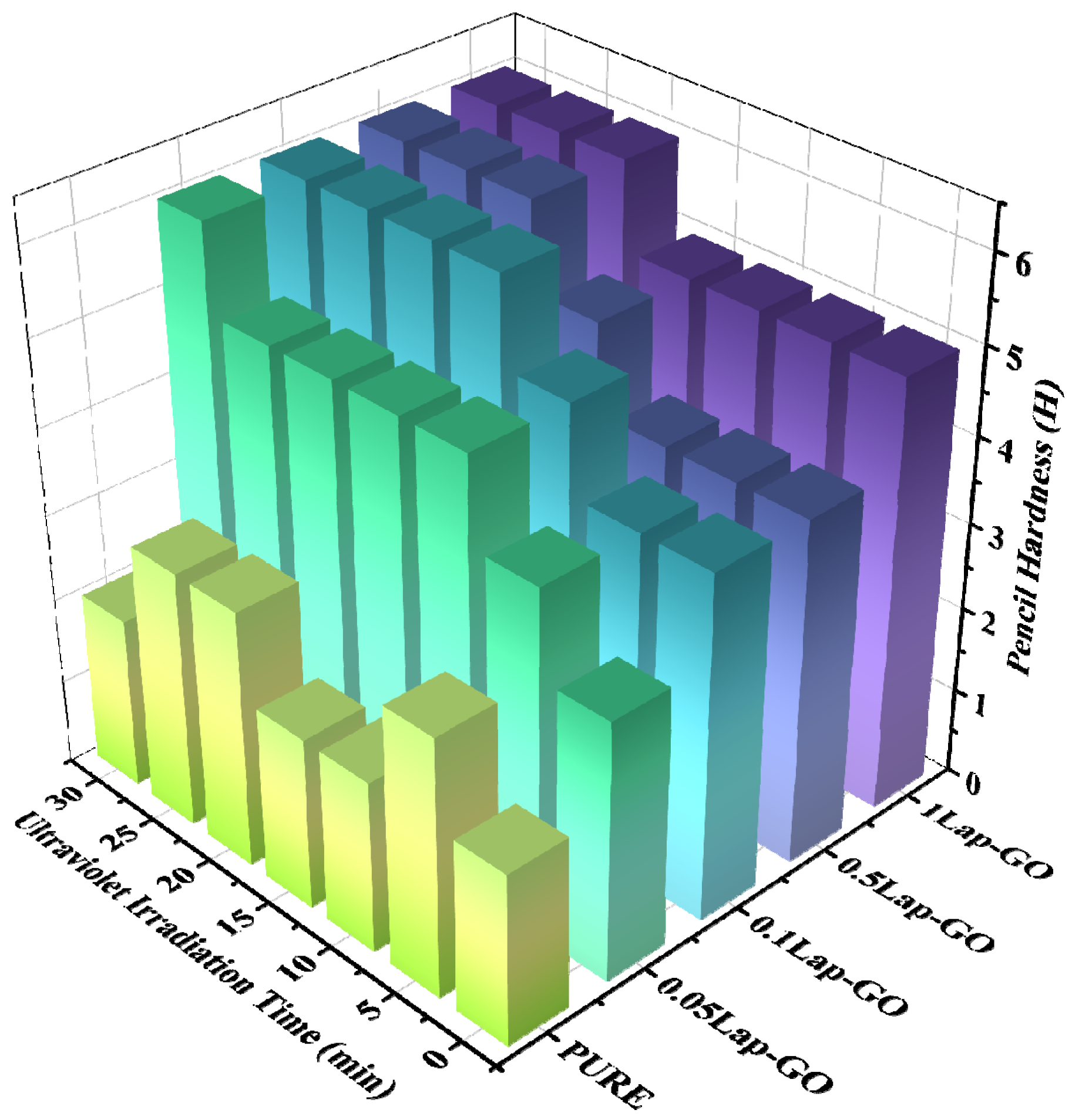
The pencil hardness of Lap-rGO/polyurethane composite coating obtained after UV reduction is shown in Figure 11. The pencil hardness of the coating increases with the increase in UV reduction time. When the Lap-GO content in the coating increases, a longer period of UV reduction results in a more significant improvement in the pencil hardness of the coating. For the 0.05Lap-GO composite coating and UV reduction, which is performed for 10 min, the pencil hardness of the sample increases by three levels compared to the pure sample.
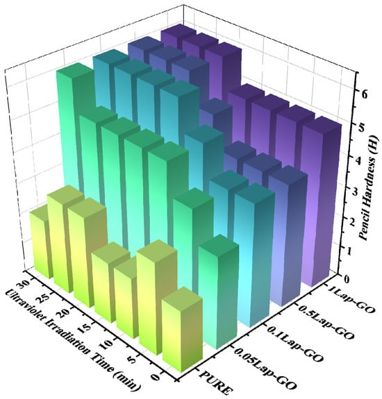
Figure 11.
Pencil hardness comparison of composite coatings with different Lap-GO contents before and after UV reduction.
Furthermore, it is also indicated that the addition of Lap-GO improves the pencil hardness of the coating, which, due to GO in Lap-GO dispersion, undergoes chemical cross-linking with the isocyanate group in the polyurethane matrix, thereby enhancing the scratch resistance of the composite coating. After UV reduction, GO transforms into a rigid rGO, further enhancing its interaction with the polyurethane matrix and improving the scratch resistance of the composite coating.
3.7. Analysis of Coating Transmittance
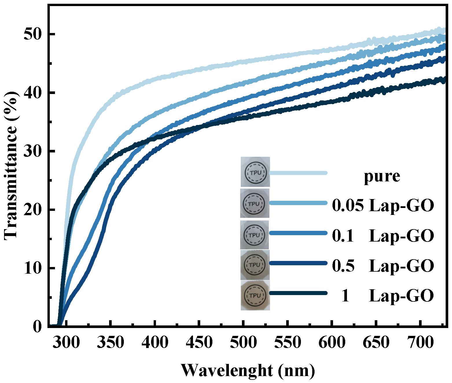
Macroscopic observation and ultraviolet transmittance were conducted on the Lap-GO/polyurethane composite coating with uniform thickness, and the optical photos and data are shown in Figure 12. The visual observation of the coating indicates that the coating quality is high in all cases and there are no surface defects such as bubbles, yellowing, or cracks. For 0.05Lap-GO and 0.1Lap-GO, the optical photos of composite coatings are similar to those of pure polyurethane coatings. For 0.5Lap-GO and 1Lap-GO, the optical photos of composite coatings showed significant color changes.
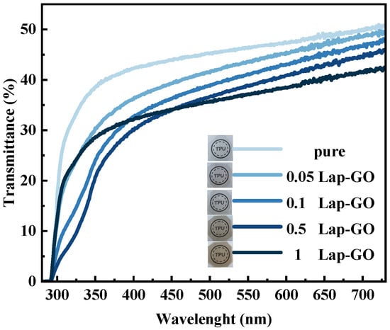
Figure 12.
Transmittance of composite coatings with different Lap-GO content in whole waveband.
The spectrum ((λ)), after testing with a UV-visible spectrophotometer, is integrated to obtain the parameter (), which can be used to determine the relative transmittance () of the composite coating to the transmittance () of the coating without Lap-GO powder [45].
When conducting a transmittance test on the coating with the addition of Lap-GO fillers, as expected, the transmittance of the composite coating is lower than that of the pure polyurethane coating. The relative transmittance () between Lap-GO/polyurethane composite coatings with different contents and pure polyurethane coatings, determined after UV reduction of the composite coating, transmittance testing, and conversion were conducted again to obtain the changes in relative transmittance of the coating, are shown in Table 3. It was found that, for the 0.05Lap-GO composite coating subjected to 10 min of UV irradiation, the transmittance of the composite coating compared to the pure polyurethane coating was above 85%, indicating that the introduction of nanofillers does not significantly reduce the transmittance, and that the addition of low-content Lap-GO and Lap-rGO has no negative impact on the transmittance of the coating. Although the composite coating exhibits a lower relative transmittance (<85%) when the content of nanofillers increases, its relative transmittance is still higher than that of traditional LED and OLED displays (40%), and can still be applied in the field of traditional optics [46].

Table 3.
Relative transmittance of Lap-GO/polyurethane composite coating and Lap-rGO/polyurethane composite coating compared to pure polyurethane coating.
3.8. Analysis of Coating WCA
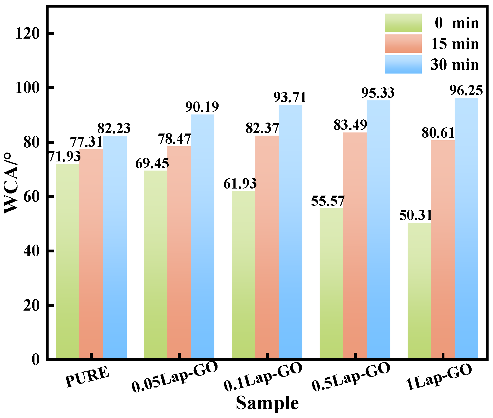
The WCA test results of the Lap-GO/polyurethane composite coating and the coating after UV reduction for different durations (0 min, 15 min, 30 min) are shown in Figure 13. It was found that between the 0.05Lap-GO composite coating and the 1Lap-GO composite coating, the WCA of the composite coating decreased from 71.93° to 50.31° with the increase in Lap-GO content, which was mainly attributed to the oxygen-containing functional groups such as the hydroxyl and carboxyl groups in the added GO, as well as the electrostatic differences between the surface and edge of Laponite. The presence of these hydrophilic groups and Na+ improves the hydrophilicity of the composite coating. UV reduction decreased the oxygen-containing functional groups on the GO surface, and the composite coating gradually changed to hydrophobicity, gradually increasing its WCA.
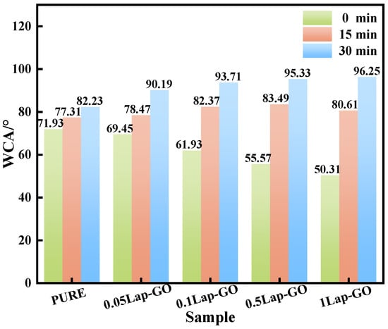
Figure 13.
WCA test of different composite coatings.
3.9. Analysis of Coating Water and Alcohol Resistance
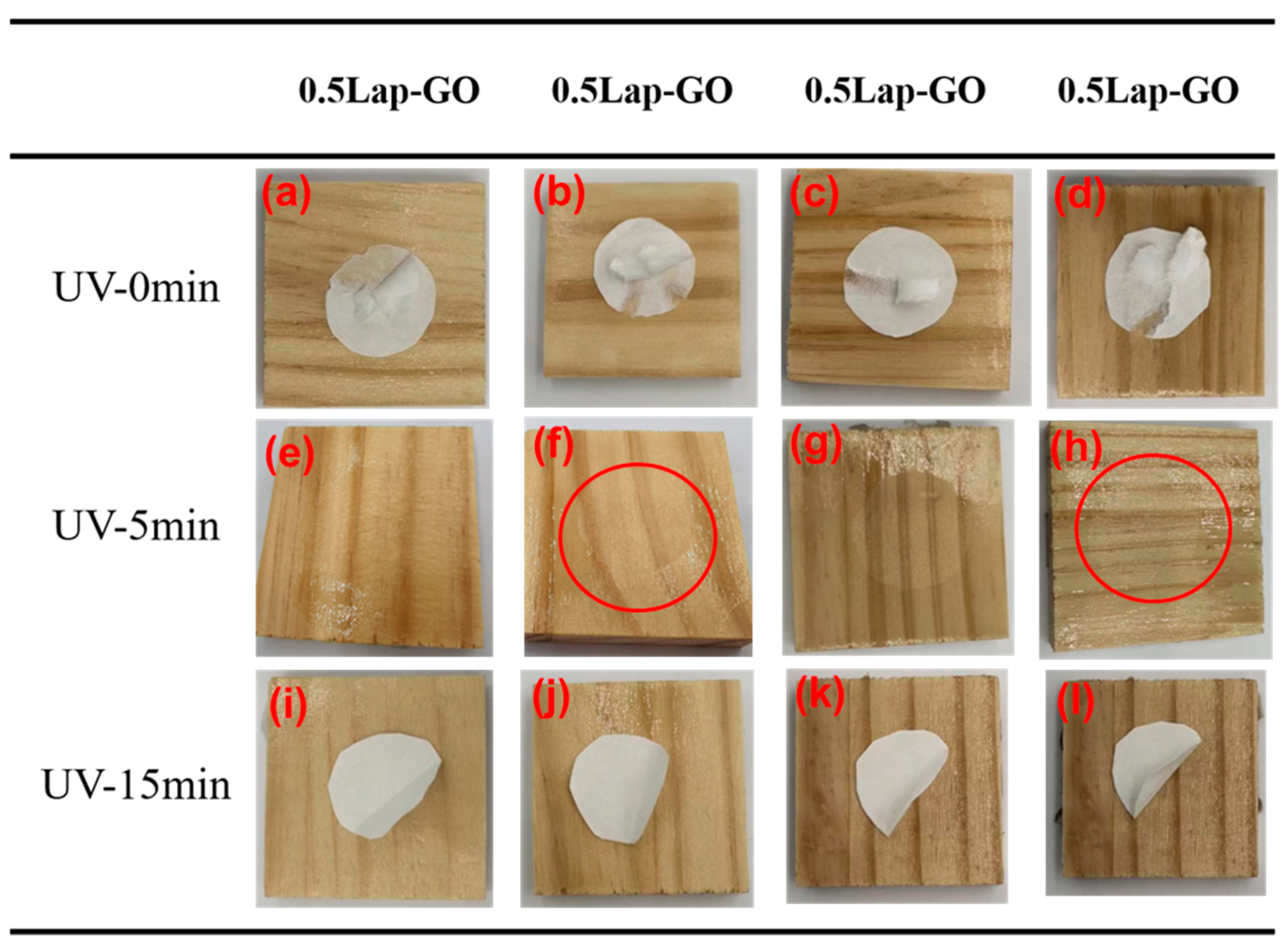
After conducting water resistance tests on the Lap-GO-modified polyurethane coating, there were no changes such as fading, swelling, cracking, or bubbling, indicating that the addition of Lap-GO had no adverse effect on the water resistance of the polyurethane coating. After the alcohol resistance test of the coating, it was found that all filter papers adhered to the surface of the coating. The addition of Lap-GO did not improve the alcohol resistance of polyurethane coatings. However, conducting alcohol resistance tests on Lap-GO/polyurethane composite coatings after UV reduction for a different duration (5 min, 10 min) found that, for high-content Lap-GO/polyurethane composite coatings, long-term UV reduction made the filter paper more prone to detachment; more specifically, after 5 min UV reduction of the composite coating with a content above 0.05 wt‰ Lap-GO, when the alcohol resistance test was carried out, there was some damage on the coating surface, as shown in the circle in the figure, the coating has a certain cracking. However, the coating surface was intact after a corresponding 10 min UV reduction, and the test filter paper fell off easily. This indicates an improvement in the alcohol resistance of the coating after UV reduction, as shown in Figure 14.

Figure 14.
(a–l) Alcohol resistance data of different Laponite/graphene-modified polyurethane composite coatings.
4. Conclusions
In summary, a Lap-GO dispersion was prepared by mixing near-monolayer GO and two-dimensional nano-transparency Laponite, and used as a filler for polyurethane coatings. Due to the electrostatic interaction between the interlayer cation of Laponite and the oxygen-containing functional groups of GO, the Lap-GO forms a co-stacked structure when Laponite is intercalated between GO layers, preventing the re-accumulation or aggregation of graphene, making the Lap-GO dispersion stable for several months without flocculation. Consequently, the synergistic effect of Laponite and GO can not only significantly improve the hardness of the coating, but also keep the coating transparent. The analysis of pencil hardness and light transmittance shows that when the Lap-GO content is 0.05 wt‰ and UV reduction 10 min, the hardness of the coated pencil increases to 5H, and the light transmittance remains above 85%. Furthermore, the Laponite/GO/polyurethane coating also has excellent cold liquid resistance and meets specific usage standards.
Author Contributions
T.J.: Writing—original draft, methodology; L.S.: Writing—review and editing, formal analysis; M.L.: Data curation and editing, conceptualization; W.H.: Writing—review and editing, conceptualization; G.C.: Writing—review and editing, supervision. All authors have read and agreed to the published version of the manuscript.
Funding
This research was funded by the Graphene Powder & Composite Research Center of Fujian Province, grant number 2017H2001, and the Xiamen Key Laboratory of Polymers & Electronic Materials, grant number 2023-01.
Institutional Review Board Statement
Not applicable.
Informed Consent Statement
Not applicable.
Data Availability Statement
Data are contained within the article.
Conflicts of Interest
The authors declare no conflict of interest.
References
- Kausar, A. Polyurethane nanocomposite coatings: State of the art and perspectives. Polym. Int. 2018, 67, 1470–1477. [Google Scholar] [CrossRef]
- Carreño, F.; Gude, M.R.; Calvo, S.; de la Fuente, R.O.; Carmona, N. Design and development of icephobic coatings based on sol-gel/modified polyurethane paints. Mater. Today Commun. 2020, 25, 101616. [Google Scholar] [CrossRef]
- Ou, B.L.; Chen, M.L.; Guo, Y.J.; Kang, Y.H.; Guo, Y.; Zhang, S.G.; Yan, J.H.; Liu, Q.Q.; Li, D.X. Preparation of novel marine antifouling polyurethane coating materials. Polym. Bull. 2018, 75, 5143–5162. [Google Scholar] [CrossRef]
- Golling, F.E.; Pires, R.; Hecking, A.; Weikard, J.; Richter, F.; Danielmeier, K.; Dijkstra, D. Polyurethanes for coatings and adhesives–chemistry and applications. Polym. Int. 2018, 68, 848–855. [Google Scholar] [CrossRef]
- Fan, W.W.; Wang, J.C.; Li, Z.J. Antiglare waterborne polyurethane/modified silica nanocomposite with balanced comprehensive properties. Polym. Test. 2021, 99, 107072. [Google Scholar] [CrossRef]
- Kong, L.L.; Xu, D.D.; He, Z.X.; Wang, F.Q.; Gui, S.H.; Fan, J.L.; Pan, X.Y.; Dai, X.H.; Dong, X.Y.; Liu, B.X.; et al. Nanocellulose-Reinforced Polyurethane for Waterborne Wood Coating. Molecules 2019, 24, 3151. [Google Scholar] [CrossRef] [PubMed]
- Nikolic, M.; Lawther, J.M.; Sanadi, A.R. Use of nanofillers in wood coatings: A scientific review. J. Coat. Technol. Res. 2015, 12, 445–461. [Google Scholar] [CrossRef]
- Cheng, D.; Wen, Y.B.; An, X.Y.; Zhu, X.H.; Ni, Y.H. TEMPO-oxidized cellulose nanofibers (TOCNs) as a green reinforcement for waterborne polyurethane coating (WPU) on wood. Carbohydr. Polym. 2016, 151, 326–334. [Google Scholar] [CrossRef]
- Xia, W.J.; Zhu, N.Q.; Hou, R.J.; Zhong, W.G.; Chen, M.Q. Preparation and Characterization of Fluorinated Hydrophobic UV-Crosslinkable Thiol-Ene Polyurethane Coatings. Coatings 2017, 7, 117. [Google Scholar] [CrossRef]
- Xu, D.D.; Liang, G.T.; Qi, Y.R.; Gong, R.Z.; Zhang, X.Q.; Zhang, Y.M.; Liu, B.X.; Kong, L.L.; Dong, X.Y.; Li, Y.F. Enhancing the Mechanical Properties of Waterborne Polyurethane Paint by Graphene Oxide for Wood Products. Polymer 2022, 14, 5456. [Google Scholar] [CrossRef]
- Re, G.; Croce, A.; D’Angelo, D.; Marchese, L.; Rinaudo, C.; Gatti, G. Application of nano-coating technology for the protection of natural lapideous materials. Surf. Coat. Technol. 2022, 441, 128507. [Google Scholar] [CrossRef]
- Fu, J.C.; Wang, L.; Yu, H.L.; Haroon, M.; Haq, F.; Shi, W.; Wu, B.; Wang, L.B. Research progress of UV-curable polyurethane acrylate-based hardening coatings. Prog. Org. Coat. 2019, 131, 82–99. [Google Scholar] [CrossRef]
- Mohanty, S.R.; Mohanty, S.; Samal, S.K.; Nayak, S.K. Acrylic-ester-polyol based novel two-component polyurethane clear coat: Evaluation of performance characteristics. J. Appl. Polym. Sci. 2021, 138, 50794. [Google Scholar] [CrossRef]
- Ma, X.Y.; Zhang, M.R. Preparation and Properties of Graphene Oxide-Modified Anti-UV Waterborne Polyurethane Nanocomposites. Nano 2020, 15, 2050005. [Google Scholar] [CrossRef]
- Wang, J.; Dai, D.; Xie, H.; Li, D.; Xiong, G.; Zhang, C. Biological Effects, Applications and Design Strategies of Medical Polyurethanes Modified by Nanomaterials. Int. J. Nanomed. 2022, 17, 6791–6819. [Google Scholar] [CrossRef]
- Tiwari, S.K.; Sahoo, S.; Wang, N.; Huczko, A. Graphene research and their outputs: Status and prospect. J. Sci. Adv. Mater. Devices 2020, 5, 10–29. [Google Scholar] [CrossRef]
- Abdel Ghany, N.A.; Elsherif, S.A.; Handal, H.T. Revolution of Graphene for different applications: State-of-the-art. Surf. Interfaces 2017, 9, 93–106. [Google Scholar] [CrossRef]
- Mason, M.J.; Coleman, B.J.; Saha, S.; Mustafa, M.M.; Green, M.J. Graphene signatures: Identifying graphite and Graphene grades via radio frequency heating. Carbon 2021, 182, 564–570. [Google Scholar] [CrossRef]
- Palermo, V.; Kinloch, I.A.; Ligi, S.; Pugno, N.M. Nanoscale Mechanics of Graphene and Graphene Oxide in Composites: A Scientific and Technological Perspective. Adv. Mater. 2016, 28, 6232–6238. [Google Scholar] [CrossRef]
- Vishnyakova, E.; Chen, G.; Brinson, B.E.; Alemany, L.B.; Billups, W.E. Structural Studies of HydroGraphenes. Acc. Chem. Res. 2017, 50, 1351–1358. [Google Scholar] [CrossRef]
- Ma, Q.; Lui, C.H.; Song, J.C.W.; Lin, Y.; Kong, J.F.; Cao, Y.; Dinh, T.H.; Nair, N.L.; Fang, W.; Watanabe, K.; et al. Giant Intrinsic Photoresponse in Pristine Graphene. Nat. Nanotechnol. 2019, 14, 145–150. [Google Scholar] [CrossRef] [PubMed]
- Li, Y.; Yang, Z.; Qiu, H.; Dai, Y.; Zheng, Q.; Li, J.; Yang, J. Self-Aligned Graphene as Anticorrosive Barrier in Waterborne Polyurethane Composite Coatings. J. Mater. Chem. A 2014, 2, 14139–14145. [Google Scholar] [CrossRef]
- Peng, S.; Iroh, J.O. Synthesis and Characterization of Crosslinked Polyurethane/Clay Nanocomposites. J. Appl. Polym. Sci. 2016, 133, 43346. [Google Scholar] [CrossRef]
- Cidonio, G.; Alcala-Orozco, C.R.; Lim, K.S.; Glinka, M.; Mutreja, I.; Kim, Y.-H.; Dawson, J.I.; Woodfield, T.B.F.; Oreffo, R.O.C. Osteogenic and Angiogenic Tissue Formation in High Fidelity Nanocomposite Laponite-Gelatin Bioinks. Biofabrication 2019, 11, 035027. [Google Scholar] [CrossRef] [PubMed]
- Liff, S.M.; Kumar, N.; McKinley, G.H. High-Performance Elastomeric Nanocomposites via Solvent-Exchange Processing. Nat. Mater. 2007, 6, 76–83. [Google Scholar] [CrossRef]
- Choi, H.Y.; Bae, C.Y.; Kim, B.K. Nanoclay Reinforced UV Curable Waterborne Polyurethane Hybrids. Prog. Org. Coat. 2010, 68, 356–362. [Google Scholar] [CrossRef]
- Rahman, M.M.; Kim, H.; Lee, W. Preparation and Characterization of Waterborne Polyurethane/Clay Nanocomposite: Effect on Water Vapor Permeability. J. Appl. Polym. Sci. 2008, 110, 3697–3705. [Google Scholar] [CrossRef]
- Fan, X.; Peng, W.; Li, Y.; Li, X.; Wang, S.; Zhang, G.; Zhang, F. Deoxygenation of Exfoliated Graphite Oxide under Alkaline Conditions: A Green Route to Graphene Preparation. Adv. Mater. 2008, 20, 4490–4493. [Google Scholar] [CrossRef]
- Jin, M.; He, W.; Wang, C.; Yu, F.; Yang, W. Covalent Modification of Graphene Oxide and Applications in Polystyrene Composites. React. Funct. Polym. 2020, 146, 104437. [Google Scholar] [CrossRef]
- Turgut, F.; Chong, C.Y.; Karaman, M.; Lau, W.J.; Gürsoy, M.; Ismail, A.F. Plasma Surface Modification of Graphene Oxide Nanosheets for the Synthesis of GO/PES Nanocomposite Ultrafiltration Membrane for Enhanced Oily Separation. J. Appl. Polym. Sci. 2023, 140, e53410. [Google Scholar] [CrossRef]
- Mishra, A.K.; Chattophadyay, S.; Nando, G.B.; Devadoss, E. Synthesis and Characterization of Elastomeric Polyurethane-Laponite Nanocomposite. Des. Monomers Polym. 2008, 11, 395–407. [Google Scholar] [CrossRef]
- Li, J.; Jiang, Z.; Gan, L.; Qiu, H.; Yang, G.; Yang, J. Functionalized Graphene/Polymer Composite Coatings for Autonomous Early-Warning of Steel Corrosion. Compos. Commun. 2018, 9, 6–10. [Google Scholar] [CrossRef]
- Chouhan, D.K.; Patro, T.U.; Harikrishnan, G.; Kumar, S.; Gupta, S.; Kumar, G.S.; Cohen, H.; Wagner, H.D. Graphene Oxide-Laponite Hybrid from Highly Stable Aqueous Dispersion. Appl. Clay Sci. 2016, 132, 105–113. [Google Scholar] [CrossRef]
- Zhang, Y.; Hu, J. Isocyanate Modified GO Shape-Memory Polyurethane Composite. Polymers 2020, 12, 118. [Google Scholar] [CrossRef] [PubMed]
- GB/T9271-2008; National Coatings and Pigments Standardization Technical Committee. Colorpaint and Varnish, Standard Test Board. China Standards Press: Beijing, China, 2008. (In Chinese)
- GB/T6739-2006; National Coatings and Pigments Standardization Technical Committee. Colorpaintand Varnish, Determination of Pencil Hardness by Pencil Method. China Standards Press: Beijing, China, 2006. (In Chinese)
- GB/T30693-2014; Examination Methods for Key Products of Quality Super-Vision, Measurement of Water Contact Angle of Plastic Film. China Standards Press: Beijing, China, 2015. (In Chinese)
- GB/T4893.1-2021; State Administration for Market Regulation and Standardization Administration of the People’s Republic of China. Test of Surface Coatings of Furniture—Part 1: Determination of Surface Resistance to Cold Liquids. China Standards Press: Beijing, China, 2021. (In Chinese)
- Yoo, J.; Lee, S.B.; Lee, C.K.; Hwang, S.W.; Kim, C.; Fujigaya, T.; Nakashima, N.; Shim, J.K. Graphene Oxide and Laponite Composite Films with High Oxygen-Barrier Properties. Nanoscale 2014, 6, 10824. [Google Scholar] [CrossRef]
- Hernandez, Y.; Nicolosi, V.; Lotya, M.; Blighe, F.M.; Sun, Z.; De, S.; McGovern, I.T.; Holland, B.; Byrne, M.; Gun’Ko, Y.K.; et al. High-Yield Production of Graphene by Liquid-Phase Exfoliation of Graphite. Nat. Nanotechnol. 2008, 3, 563–568. [Google Scholar] [CrossRef]
- Alhassan, S.M.; Qutubuddin, S.; Schiraldi, D.A. Graphene Arrested in Laponite–Water Colloidal Glass. Langmuir 2012, 28, 4009–4015. [Google Scholar] [CrossRef]
- Ding, S.-N.; Zheng, C.-L.; Wan, N.; Cosnier, S. Graphene/Clay Composite Electrode Formed by Exfoliating Graphite with Laponite for Simultaneous Determination of Ascorbic Acid, Dopamine, and Uric Acid. Monatshefte Chem. Chem. Mon. 2014, 145, 1389–1394. [Google Scholar] [CrossRef]
- Wu, W.; Dong, Z.; He, J.; Yu, J.; Zhang, J. Transparent Cellulose/Laponite Nanocomposite Films. J. Mater. Sci. 2016, 51, 4125–4133. [Google Scholar] [CrossRef]
- Li, J.; Cui, J.; Yang, Z.; Qiu, H.; Tang, Z.; Yang, J. Stabilizing Graphene Layers by Intercalating Laponite between Them. New Carbon Mater. 2018, 33, 19–25. [Google Scholar] [CrossRef]
- Domene-López, D.; Sarabia-Riquelme, R.; García-Quesada, J.C.; Martin-Gullon, I. Custom-Made Chemically Modified Graphene Oxide to Improve the Anti-Scratch Resistance of Urethane-Acrylate Transparent Coatings. Coatings 2019, 9, 408. [Google Scholar] [CrossRef]
- Shin, S.; Hwang, B.; Zhao, Z.-J.; Jeon, S.H.; Jung, J.; Lee, J.-H.; Ju, B.-K.; Jeong, J.-H. Transparent Displays Utilizing Nanopatterned Quantum Dot Films. Sci. Rep. 2018, 8, 2463. [Google Scholar] [CrossRef] [PubMed]
Disclaimer/Publisher’s Note: The statements, opinions and data contained in all publications are solely those of the individual author(s) and contributor(s) and not of MDPI and/or the editor(s). MDPI and/or the editor(s) disclaim responsibility for any injury to people or property resulting from any ideas, methods, instructions or products referred to in the content. |
© 2023 by the authors. Licensee MDPI, Basel, Switzerland. This article is an open access article distributed under the terms and conditions of the Creative Commons Attribution (CC BY) license (https://creativecommons.org/licenses/by/4.0/).

