
Optimization of Pavement Structure Using High-Modulus Asphalt Coating Considering the Effects of Base-Course Combinations

Abstract
1. Introduction
2. Calculation Model
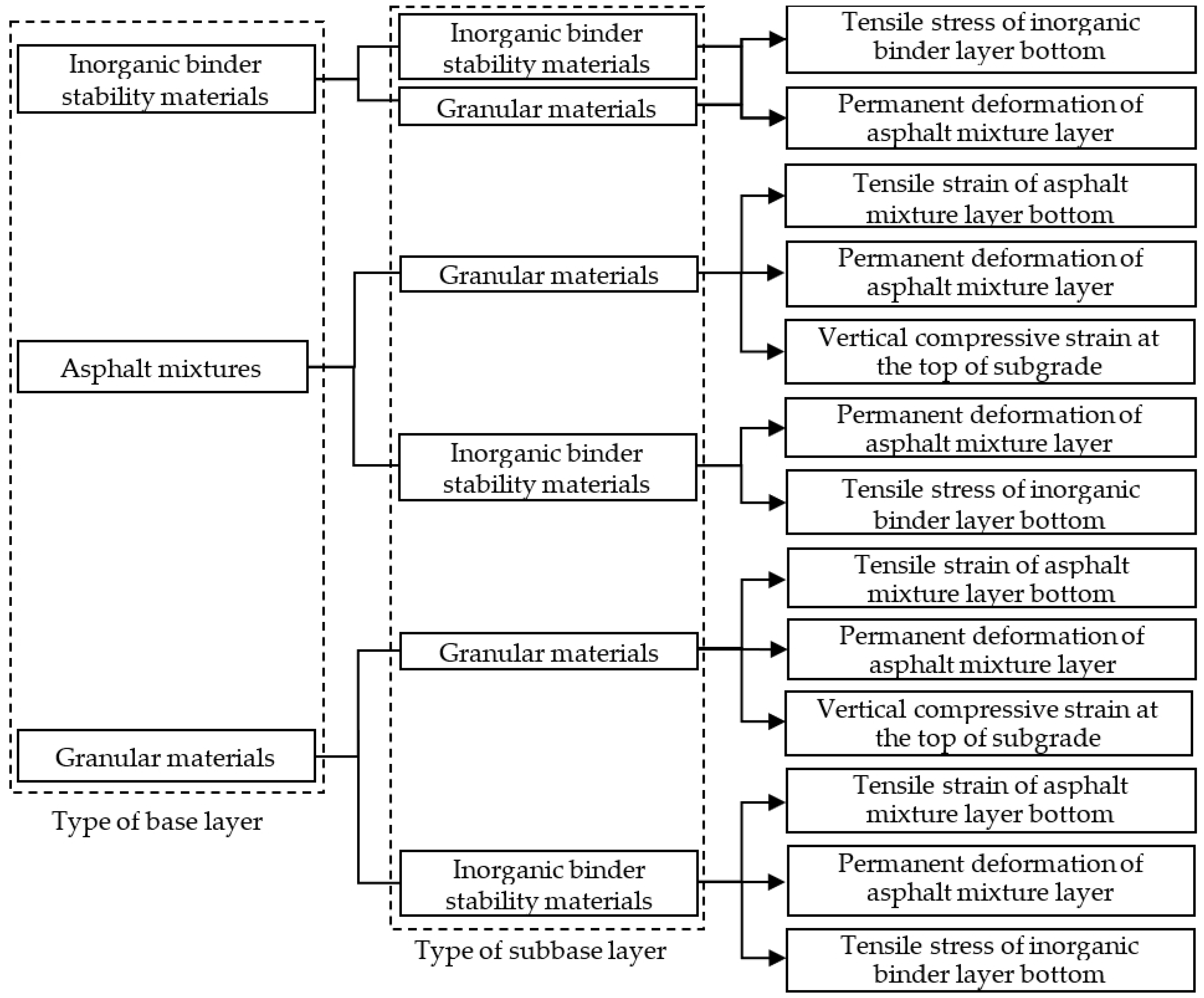
2.1. Pavement Mechanical Index
2.2. HMAC Parameters
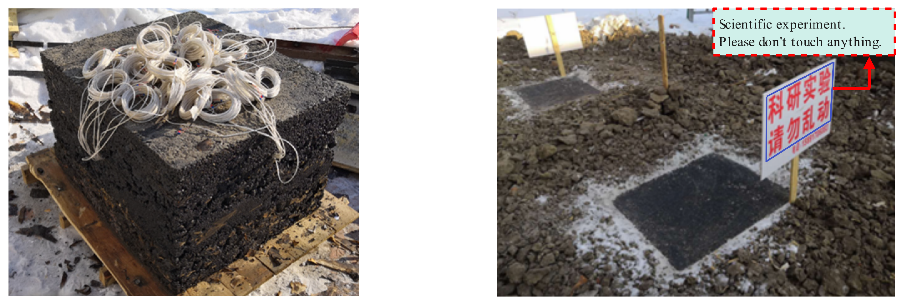
2.3. Verification
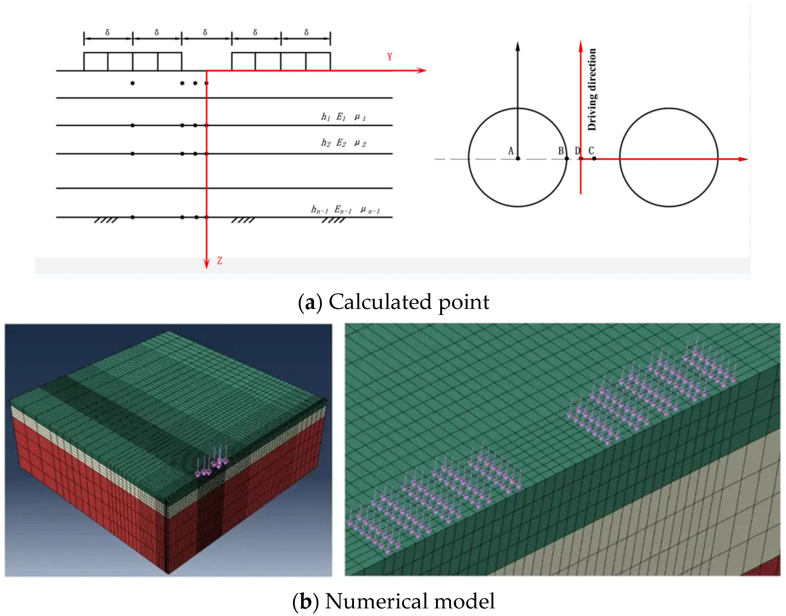
2.4. Pavement Structure Model
3. Mechanical Responses
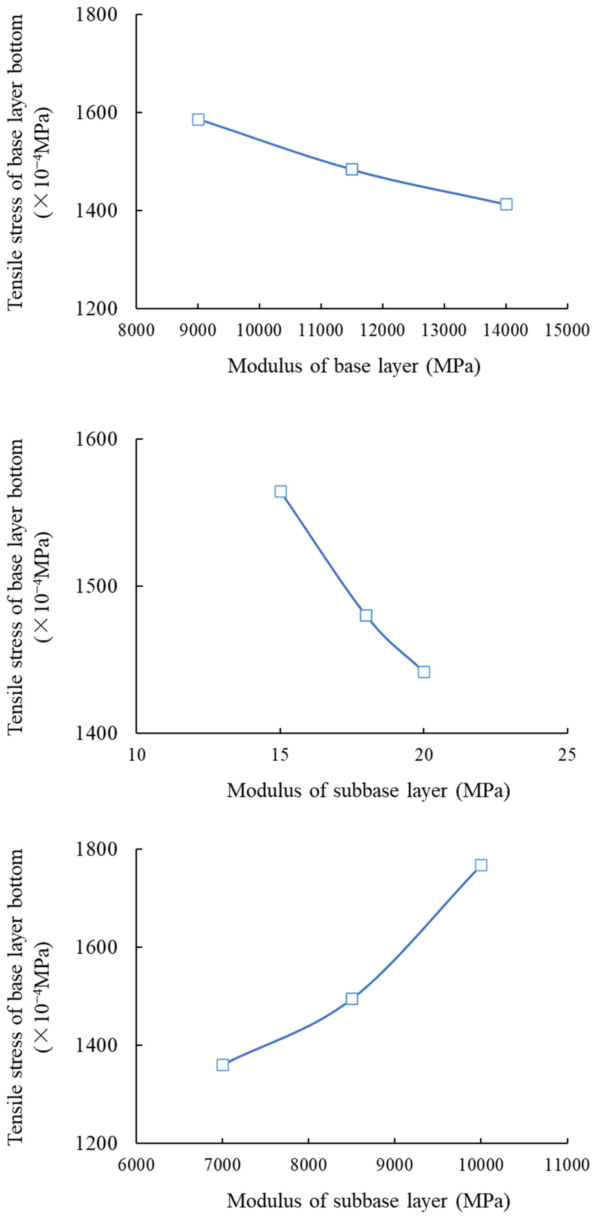
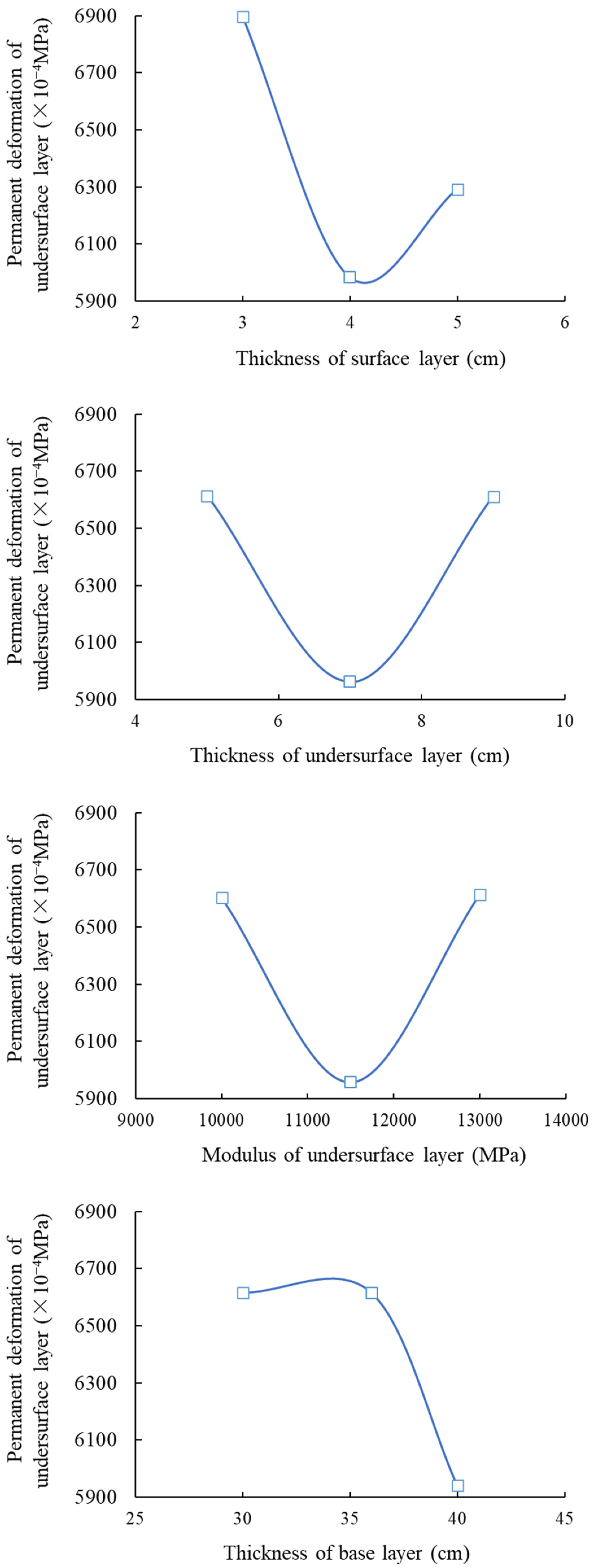
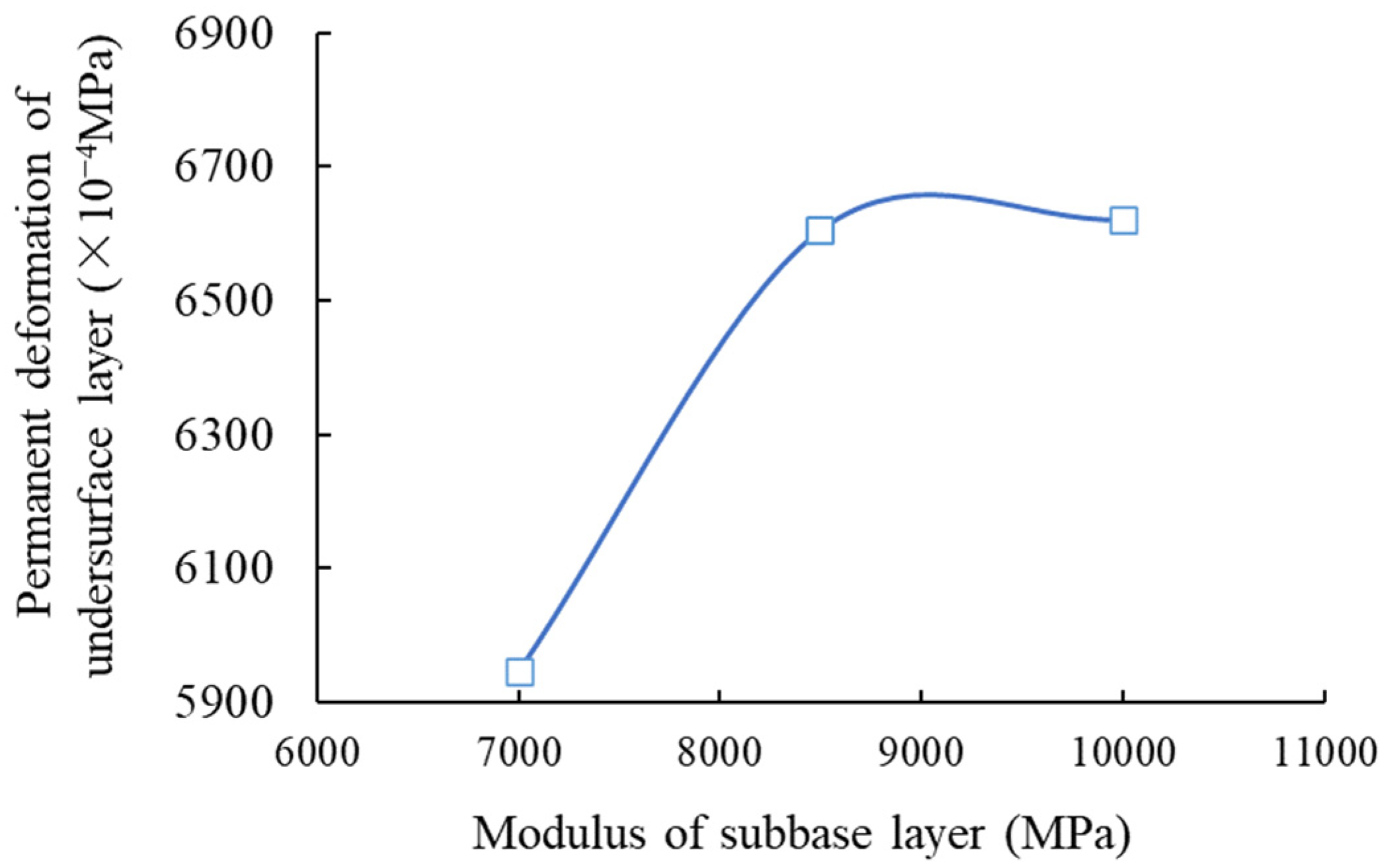
3.1. Condition No. 1 (HMAC Surface Layer + Asphalt Concrete Undersurface Layer + Inorganic Binder Base Layer + Inorganic Binder Subbase Layer)
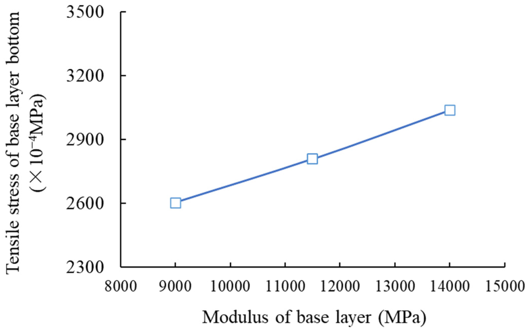
3.2. Condition No. 2 (HMAC Surface Layer + Asphalt Concrete Undersurface Layer + Inorganic Binder Base Layer + Granular Base Subbase)
3.3. Condition No. 3 (HMAC Surface Layer + Asphalt Concrete Undersurface Layer + Asphalt Mixture Base Layer + Granular Subbase Layer)
3.4. Condition No. 4 (HMAC Surface Layer + Asphalt Concrete Undersurface Layer + Asphalt Mixture Base Layer + Inorganic Binder Subbase Layer)
3.5. Condition No. 5 (HMAC Surface Layer + Asphalt Concrete Undersurface Layer + Granular Base Layer + Inorganic Binder Subbase Layer)
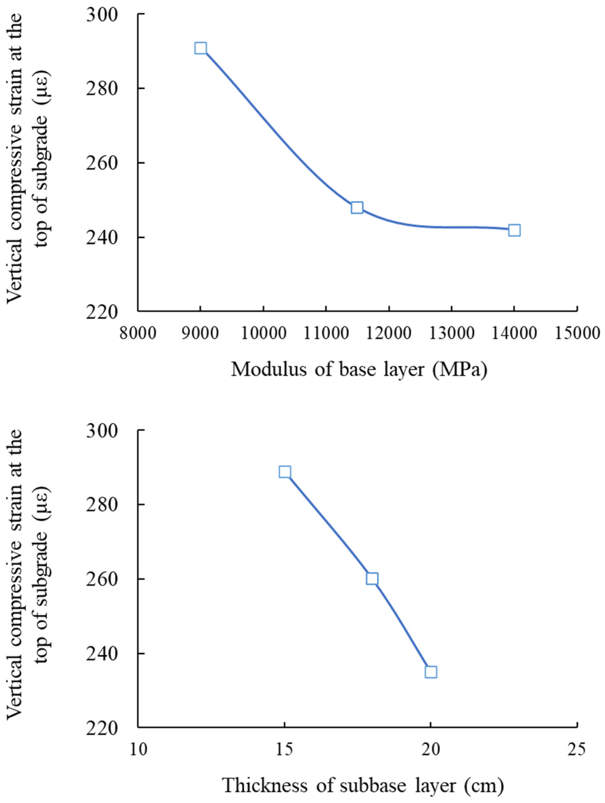
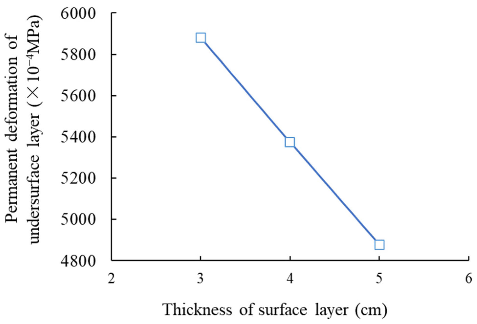
3.6. Condition No. 6 (HMAC Surface Layer + Asphalt Concrete Undersurface Layer + Granular Base Layer + Inorganic Binder Base Layer)
4. Discussion
5. Conclusions
- The influences of pavement thickness and material modulus on the mechanical response of HMAC pavement under different combinations of base and subbase layer are revealed. The effect of base layer type on mechanical response is more significant than that of subbase layer type.
- Based on mechanical response laws, key control indices that affect the mechanical response of HMAC pavement under various base and subbase layer combinations are proposed.
- For a granular material base layer, surface and undersurface layer thickness are the key factors for mechanical response. A thick surface layer and thin undersurface layer are beneficial for the mechanical response of pavement structure.
- For an asphalt mixture base layer, surface and base layer thickness are the key factors for mechanical response. A thick surface layer and base layer provide a low mechanical response in the pavement structure.
- For an inorganic binder mixture base layer, base layer thickness, subbase layer modulus, and base layer modulus are the key factors for mechanical response. A thick base layer and low base and subbase moduli are beneficial for the mechanical response of the pavement structure.
- Based on the principle of optimal mechanical response and considering cost-effectiveness, six recommended HMAC pavement structure configurations for various base-courses are proposed.
Author Contributions
Funding
Informed Consent Statement
Data Availability Statement
Conflicts of Interest
References
- Zhang, C.; Wang, H.; You, Z.; Liu, Y.; Yang, X.; Xiao, J. Prediction on rutting decay curves for asphalt pavement based on the pavement-ME and matter element analysis. Int. J. Pavement Res. Technol. 2017, 10, 466–475. [Google Scholar] [CrossRef]
- Ren, J.; Xue, B.; Zhang, L.; Liu, W.; Li, D.; Xu, Y. Characterization and prediction of rutting resistance of rock asphalt mixture under the coupling effect of water and high-temperature. Constr. Build. Mater. 2020, 254, 119316. [Google Scholar] [CrossRef]
- Nadkarni, V.M.; Shenoy, A.V.; Mathew, J. Thermomechanical behavior of modified asphalts. Ind. Eng. Chem. Prod. Res. Dev. 1985, 24, 478–484. [Google Scholar] [CrossRef]
- Ford, N.M. Rubber modified asphalt concrete pavement. Rubber Chem. Technol. 1983, 56, 279–280. [Google Scholar]
- Qi, X.; Sebaaly, P.E.; Epps, J.A. Evaluation of polymer-modified asphalt concrete mixtures. J. Mater. Civ. Eng. 1995, 7, 117–124. [Google Scholar] [CrossRef]
- Kök, B.V.; Yilmaz, M.; Guler, M. Evaluation of high temperature performance of SBS+ Gilsonite modified binder. Fuel 2011, 90, 3093–3099. [Google Scholar] [CrossRef]
- Moghaddam, T.B.; Baaj, H. Rheological characterization of high-modulus asphalt mix with modified asphalt binders. Constr. Build. Mater. 2018, 193, 142–152. [Google Scholar] [CrossRef]
- Kamran, F.; Ghasemirad, A.; Moghaddam, T.B.; Bayat, A.; Hashemian, L. Performance evaluation of high modulus asphalt concrete (HMAC) prepared using asphaltenes-modified binders. J. Test. Eval. 2022, 50, 2636–2651. [Google Scholar] [CrossRef]
- Si, C.; Cao, H.; Chen, E.; You, Z.; Tian, R.; Zhang, R.; Gao, J. Dynamic response analysis of rutting resistance performance of high modulus asphalt concrete pavement. Appl. Sci. 2018, 8, 2701. [Google Scholar] [CrossRef]
- Ye, F.; Liu, Z.; Zhu, X.; Zhu, W.; Cai, G.; Wang, L. Research on integrated electrical and mechanical response of piezoelectric asphalt pavement material under bidirectional cyclic loads. Constr. Build. Mater. 2023, 375, 130957. [Google Scholar] [CrossRef]
- Norouzi, A.; Kim, D.; Kim, Y.R. Numerical evaluation of pavement design parameters for the fatigue cracking and rutting performance of asphalt pavements. Mater. Struct. 2016, 49, 3619–3634. [Google Scholar] [CrossRef]
- Lv, S.; Yuan, J.; Peng, X.; Zhang, N.; Liu, H.; Luo, X. A structural design for semi-rigid base asphalt pavement based on modulus optimization. Constr. Build. Mater. 2021, 302, 124216. [Google Scholar] [CrossRef]
- Shirzad, S.; Aguirre, M.A.; Bonilla, L.; Elseifi, M.A.; Cooper, S.; Mohammad, L.N. Mechanistic-empirical pavement performance of asphalt mixtures with recycled asphalt shingles. Constr. Build. Mater. 2018, 160, 687–697. [Google Scholar] [CrossRef]
- Pan, Q.; Zheng, C.; Song, X.; Lv, S.; Yu, H.; Zhang, J.; Cabrera, M.B.; Liu, H. Mechanical analysis of asphalt pavement based on bimodulus elasticity theory. Constr. Build. Mater. 2021, 301, 124084. [Google Scholar] [CrossRef]
- Jiang, X.; Zeng, C.; Gao, X.; Liu, Z.; Qiu, Y. 3D FEM analysis of flexible base asphalt pavement structure under non-uniform tyre contact pressure. Int. J. Pavement Eng. 2019, 20, 999–1011. [Google Scholar] [CrossRef]
- Li, Q.; Chen, Z. Numerical analysis and conversion of dynamic and static deflection of asphalt pavement under FWD loading. Constr. Build. Mater. 2023, 367, 129513. [Google Scholar] [CrossRef]
- Liu, H.; Ge, W.; Pan, Q.; Hu, R.; Lv, S.; Huang, T. Characteristics and analysis of dynamic strain response on typical asphalt pavement using Fiber Bragg Grating sensing technology. Constr. Build. Mater. 2021, 310, 125242. [Google Scholar] [CrossRef]
- Rys, D. Consideration of dynamic loads in the determination of axle load spectra for pavement design. Road Mater. Pavement 2021, 22, 1309–1328. [Google Scholar] [CrossRef]
- Assogba, O.C.; Tan, Y.; Zhou, X.; Zhang, C.; Anato, J.N. Numerical investigation of the mechanical response of semi-rigid base asphalt pavement under traffic load and nonlinear temperature gradient effect. Constr. Build. Mater. 2020, 235, 117406. [Google Scholar] [CrossRef]
- Zeiada, W.; Dabous, S.A.; Hamad, K.; Al-Ruzouq, R.; Khalil, M.A. Machine learning for pavement performance modelling in warm climate regions. Arab. J. Sci. Eng. 2020, 45, 4091–4109. [Google Scholar] [CrossRef]
- JTG D50; Specifications for Design of Highway Asphalt Pavement. Ministry of Communications of the People’s Republic of China: Beijing, China, 2017; pp. 21–22.


| Design Index | Mechanical Response | Vertical Position |
|---|---|---|
| Tensile strain of asphalt mixture layer bottom | Horizontal tensile strain along running direction | Asphalt mixture layer bottom |
| Tensile stress of inorganic binder-stabilized material layer bottom | Horizontal tensile stress along the driving direction | Inorganic binder-stabilized material layer bottom |
| Permanent deformation of asphalt mixture layer | Vertical compressive stress | Top surface of each layer of asphalt mixture layer |
| Vertical compressive strain at the top of subgrade | Vertical compressive strain | Subgrade top |
| Working Condition | Surface Layer | Undersurface Layer | Base Layer | Subbase Layer |
|---|---|---|---|---|
| No. 1 | HMAC | AC-25 asphalt mixture | Cement-stabilized macadam | Cement-stabilized macadam |
| No. 2 | Cement-stabilized macadam | Graded broken stone | ||
| No. 3 | Asphalt-treated base | Graded broken stone | ||
| No. 4 | Asphalt-treated base | Cement-stabilized macadam | ||
| No. 5 | Graded broken stone | Cement-stabilized macadam | ||
| No. 6 | Graded broken stone | Graded broken stone |
| Frequency (Hz) | 0.1 | 0.5 | 1 | 5 | 10 | 25 |
| Modulus (MPa) | 8700 | 12,226 | 13,667 | 15,731 | 16,791 | 18,868 |
| Tensile Strength (MPa) | Elongation at Break (%) | Density (g·cm−3) | Melt Flow Rate (g/10 min) | Rockwell Hardness | Vicat Softening Point (°C) | Resin Content (%) | Particle Diameter (mm) |
|---|---|---|---|---|---|---|---|
| 18 | 28 | 0.94 | 1.6 | 62 | 126 | 69 | 4 |
| Working Condition | Design Index | Layer | Test Value | Simulation Value | Error (%) |
|---|---|---|---|---|---|
| No. 1 | Tensile stress of layer bottom (×10−4 MPa) | Subbase layer | 1069 | 976 | 8.7 |
| Base layer | 1480 | 1567 | 5.9 | ||
| Permanent deformation (×10−4 MPa) | Undersurface layer | 7099 | 6453 | 9.1 | |
| No. 2 | Tensile stress of layer bottom (×10−4 MPa) | Base layer | 3212 | 2926 | 8.9 |
| Permanent deformation (×10−4 MPa) | Undersurface layer | 5482 | 6101 | 11.3 | |
| No. 3 | Permanent deformation (×10−4 MPa) | Undersurface layer | 5986 | 6399 | 6.9 |
| Base layer | 3144 | 3370 | 7.2 | ||
| Vertical compressive strain (με) | Subgrade | 19.0 | 20.7 | 8.9 | |
| Tensile strain of layer bottom (με) | Surface layer | 29.2 | 30.8 | 5.3 | |
| Undersurface layer | 60.9 | 58.1 | 4.6 | ||
| Base layer | 46.0 | 49.4 | 7.3 | ||
| No. 4 | Tensile stress of layer bottom (×10−4 MPa) | Subbase layer | 2346 | 2463 | 5.0 |
| Permanent deformation (×10−4 MPa) | Undersurface layer | 7636 | 6590 | 13.7 | |
| Base layer | 3937 | 4414 | 12.1 | ||
| No. 5 | Tensile stress of layer bottom (×10−4 MPa) | Subbase layer | 2733 | 3003 | 9.9 |
| Permanent deformation (×10−4 MPa) | Undersurface layer | 6178 | 5443 | 11.9 | |
| Tensile strain of layer bottom (με) | Surface layer | 22.1 | 19.9 | 9.8 | |
| Undersurface layer | 57.7 | 63.9 | 10.7 | ||
| No. 6 | Tensile strain of layer bottom (με) | Surface layer | 20.0 | 21.9 | 9.7 |
| Undersurface layer | 84.4 | 77.1 | 8.6 | ||
| Vertical compressive strain (με) | Subgrade | 270 | 286 | 6.1 | |
| Permanent deformation (×10−4 MPa) | Undersurface layer | 5788 | 5371 | 7.2 |
| No. | Surface Layer | Undersurface Layer | Base Layer | Subbase Layer | Soil Matrix | ||||
|---|---|---|---|---|---|---|---|---|---|
| Thickness (cm) | Modulus (MPa) | Thickness (cm) | Modulus (MPa) | Thickness (cm) | Modulus (MPa) | Thickness (cm) | Modulus (MPa) | Modulus (MPa) | |
| 1-1 | 3 | 16,791 | 5 | 10,000 | 30 | 9000 | 15 | 7000 | 50 |
| 1-2 | 3 | 7 | 11,500 | 36 | 11,500 | 18 | 8500 | 50 | |
| 1-3 | 3 | 9 | 13,000 | 40 | 14,000 | 20 | 10,000 | 50 | |
| 1-4 | 4 | 5 | 10,000 | 36 | 11,500 | 20 | 10,000 | 50 | |
| 1-5 | 4 | 7 | 11,500 | 40 | 14,000 | 15 | 7000 | 50 | |
| 1-6 | 4 | 9 | 13,000 | 30 | 9000 | 18 | 8500 | 50 | |
| 1-7 | 5 | 5 | 11,500 | 30 | 14,000 | 18 | 10,000 | 50 | |
| 1-8 | 5 | 7 | 13,000 | 36 | 9000 | 20 | 7000 | 50 | |
| 1-9 | 5 | 9 | 10,000 | 40 | 11,500 | 15 | 8500 | 50 | |
| 1-10 | 3 | 5 | 13,000 | 40 | 11,500 | 18 | 7000 | 50 | |
| 1-11 | 3 | 7 | 10,000 | 30 | 14,000 | 20 | 8500 | 50 | |
| 1-12 | 3 | 9 | 11,500 | 36 | 9000 | 15 | 10,000 | 50 | |
| 1-13 | 4 | 5 | 11,500 | 40 | 9000 | 20 | 8500 | 50 | |
| 1-14 | 4 | 7 | 13,000 | 30 | 11,500 | 15 | 10,000 | 50 | |
| 1-15 | 4 | 9 | 10,000 | 36 | 14,000 | 18 | 7000 | 50 | |
| 1-16 | 5 | 5 | 13,000 | 36 | 14,000 | 15 | 8500 | 50 | |
| 1-17 | 5 | 7 | 10,000 | 40 | 9000 | 18 | 10,000 | 50 | |
| 1-18 | 5 | 9 | 11,500 | 30 | 11,500 | 20 | 7000 | 50 | |
| No. | Surface Layer | Undersurface Layer | Base Layer | Subbase Layer | Soil Matrix | ||||
|---|---|---|---|---|---|---|---|---|---|
| Thickness (cm) | Modulus (MPa) | Thickness (cm) | Modulus (MPa) | Thickness (cm) | Modulus (MPa) | Thickness (cm) | Modulus (MPa) | Modulus (MPa) | |
| 2-1 | 3 | 16,791 | 5 | 10,000 | 30 | 9000 | 15 | 200 | 50 |
| 2-2 | 3 | 7 | 11,500 | 36 | 11,500 | 18 | 320 | 50 | |
| 2-3 | 3 | 9 | 13,000 | 40 | 14,000 | 20 | 440 | 50 | |
| 2-4 | 4 | 5 | 10,000 | 36 | 11,500 | 20 | 440 | 50 | |
| 2-5 | 4 | 7 | 11,500 | 40 | 14,000 | 15 | 200 | 50 | |
| 2-6 | 4 | 9 | 13,000 | 30 | 9000 | 18 | 320 | 50 | |
| 2-7 | 5 | 5 | 11,500 | 30 | 14,000 | 18 | 440 | 50 | |
| 2-8 | 5 | 7 | 13,000 | 36 | 9000 | 20 | 200 | 50 | |
| 2-9 | 5 | 9 | 10,000 | 40 | 11,500 | 15 | 320 | 50 | |
| 2-10 | 3 | 5 | 13,000 | 40 | 11,500 | 18 | 200 | 50 | |
| 2-11 | 3 | 7 | 10,000 | 30 | 14,000 | 20 | 320 | 50 | |
| 2-12 | 3 | 9 | 11,500 | 36 | 9000 | 15 | 440 | 50 | |
| 2-13 | 4 | 5 | 11,500 | 40 | 9000 | 20 | 320 | 50 | |
| 2-14 | 4 | 7 | 13,000 | 30 | 11,500 | 15 | 440 | 50 | |
| 2-15 | 4 | 9 | 10,000 | 36 | 14,000 | 18 | 200 | 50 | |
| 2-16 | 5 | 5 | 13,000 | 36 | 14,000 | 15 | 320 | 50 | |
| 2-17 | 5 | 7 | 10,000 | 40 | 9000 | 18 | 440 | 50 | |
| 2-18 | 5 | 9 | 11,500 | 30 | 11,500 | 20 | 200 | 50 | |
| No. | Surface Layer | Undersurface Layer | Base Layer | Subbase Layer | Soil Matrix | ||||
|---|---|---|---|---|---|---|---|---|---|
| Thickness (cm) | Modulus (MPa) | Thickness (cm) | Modulus (MPa) | Thickness (cm) | Modulus (MPa) | Thickness (cm) | Modulus (MPa) | Thickness (cm) | |
| 3-1 | 3 | 16,791 | 5 | 10,000 | 10 | 7000 | 20 | 200 | 50 |
| 3-2 | 3 | 7 | 11,500 | 15 | 9000 | 25 | 320 | 50 | |
| 3-3 | 3 | 9 | 13,000 | 20 | 11,000 | 30 | 440 | 50 | |
| 3-4 | 4 | 5 | 10,000 | 15 | 9000 | 30 | 440 | 50 | |
| 3-5 | 4 | 7 | 11,500 | 20 | 11,000 | 20 | 200 | 50 | |
| 3-6 | 4 | 9 | 13,000 | 10 | 7000 | 25 | 320 | 50 | |
| 3-7 | 5 | 5 | 11,500 | 10 | 11,000 | 25 | 440 | 50 | |
| 3-8 | 5 | 7 | 13,000 | 15 | 7000 | 30 | 200 | 50 | |
| 3-9 | 5 | 9 | 10,000 | 20 | 9000 | 20 | 320 | 50 | |
| 3-10 | 3 | 5 | 13,000 | 20 | 9000 | 25 | 200 | 50 | |
| 3-11 | 3 | 7 | 10,000 | 10 | 11,000 | 30 | 320 | 50 | |
| 3-12 | 3 | 9 | 11,500 | 15 | 7000 | 20 | 440 | 50 | |
| 3-13 | 4 | 5 | 11,500 | 20 | 7000 | 30 | 320 | 50 | |
| 3-14 | 4 | 7 | 13,000 | 10 | 9000 | 20 | 440 | 50 | |
| 3-15 | 4 | 9 | 10,000 | 15 | 11,000 | 25 | 200 | 50 | |
| 3-16 | 5 | 5 | 13,000 | 15 | 11,000 | 20 | 320 | 50 | |
| 3-17 | 5 | 7 | 10,000 | 20 | 7000 | 25 | 440 | 50 | |
| 3-18 | 5 | 9 | 11,500 | 10 | 9000 | 30 | 200 | 50 | |
| No. | Surface Layer | Undersurface Layer | Base Layer | Subbase Layer | Soil Matrix | ||||
|---|---|---|---|---|---|---|---|---|---|
| Thickness (cm) | Modulus (MPa) | Thickness (cm) | Modulus (MPa) | Thickness (cm) | Modulus (MPa) | Thickness (cm) | Modulus (MPa) | Thickness (cm) | |
| 4-1 | 3 | 16,791 | 5 | 10,000 | 10 | 7000 | 20 | 7000 | 50 |
| 4-2 | 3 | 7 | 11,500 | 15 | 9000 | 25 | 8500 | 50 | |
| 4-3 | 3 | 9 | 13,000 | 20 | 11,000 | 30 | 10,000 | 50 | |
| 4-4 | 4 | 5 | 10,000 | 15 | 9000 | 30 | 10,000 | 50 | |
| 4-5 | 4 | 7 | 11,500 | 20 | 11,000 | 20 | 7000 | 50 | |
| 4-6 | 4 | 9 | 13,000 | 10 | 7000 | 25 | 8500 | 50 | |
| 4-7 | 5 | 5 | 11,500 | 10 | 11,000 | 25 | 10,000 | 50 | |
| 4-8 | 5 | 7 | 13,000 | 15 | 7000 | 30 | 7000 | 50 | |
| 4-9 | 5 | 9 | 10,000 | 20 | 9000 | 20 | 8500 | 50 | |
| 4-10 | 3 | 5 | 13,000 | 20 | 9000 | 25 | 7000 | 50 | |
| 4-11 | 3 | 7 | 10,000 | 10 | 11,000 | 30 | 8500 | 50 | |
| 4-12 | 3 | 9 | 11,500 | 15 | 7000 | 20 | 10,000 | 50 | |
| 4-13 | 4 | 5 | 11,500 | 20 | 7000 | 30 | 8500 | 50 | |
| 4-14 | 4 | 7 | 13,000 | 10 | 9000 | 20 | 10,000 | 50 | |
| 4-15 | 4 | 9 | 10,000 | 15 | 11,000 | 25 | 7000 | 50 | |
| 4-16 | 5 | 5 | 13,000 | 15 | 11,000 | 20 | 8500 | 50 | |
| 4-17 | 5 | 7 | 10,000 | 20 | 7000 | 25 | 10,000 | 50 | |
| 4-18 | 5 | 9 | 11,500 | 10 | 9000 | 30 | 7000 | 50 | |
| No. | Surface Layer | Undersurface Layer | Base Layer | Subbase Layer | Soil Matrix | ||||
|---|---|---|---|---|---|---|---|---|---|
| Thickness (cm) | Modulus (MPa) | Thickness (cm) | Modulus (MPa) | Thickness (cm) | Modulus(MPa) | Thickness (cm) | Modulus (MPa) | Thickness (cm) | |
| 5-1 | 3 | 16,791 | 5 | 10,000 | 30 | 300 | 15 | 7000 | 50 |
| 5-2 | 3 | 7 | 11,500 | 36 | 500 | 18 | 8500 | 50 | |
| 5-3 | 3 | 9 | 13,000 | 40 | 700 | 20 | 10,000 | 50 | |
| 5-4 | 4 | 5 | 10,000 | 36 | 500 | 20 | 10,000 | 50 | |
| 5-5 | 4 | 7 | 11,500 | 40 | 700 | 15 | 7000 | 50 | |
| 5-6 | 4 | 9 | 13,000 | 30 | 300 | 18 | 8500 | 50 | |
| 5-7 | 5 | 5 | 11,500 | 30 | 700 | 18 | 10,000 | 50 | |
| 5-8 | 5 | 7 | 13,000 | 36 | 300 | 20 | 7000 | 50 | |
| 5-9 | 5 | 9 | 10,000 | 40 | 500 | 15 | 8500 | 50 | |
| 5-10 | 3 | 5 | 13,000 | 40 | 500 | 18 | 7000 | 50 | |
| 5-11 | 3 | 7 | 10,000 | 30 | 700 | 20 | 8500 | 50 | |
| 5-12 | 3 | 9 | 11,500 | 36 | 300 | 15 | 10,000 | 50 | |
| 5-13 | 4 | 5 | 11,500 | 40 | 300 | 20 | 8500 | 50 | |
| 5-14 | 4 | 7 | 13,000 | 30 | 500 | 15 | 10,000 | 50 | |
| 5-15 | 4 | 9 | 10,000 | 36 | 700 | 18 | 7000 | 50 | |
| 5-16 | 5 | 5 | 13,000 | 36 | 700 | 15 | 8500 | 50 | |
| 5-17 | 5 | 7 | 10,000 | 40 | 300 | 18 | 10,000 | 50 | |
| 5-18 | 5 | 9 | 11,500 | 30 | 500 | 20 | 7000 | 50 | |
| No. | Surface Layer | Undersurface Layer | Base Layer | Subbase Layer | Soil Matrix | ||||
|---|---|---|---|---|---|---|---|---|---|
| Thickness (cm) | Modulus (MPa) | Thickness (cm) | Modulus (MPa) | Thickness (cm) | Modulus (MPa) | Thickness (cm) | Modulus (MPa) | Thickness (cm) | |
| 6-1 | 3 | 16,791 | 5 | 10,000 | 30 | 300 | 15 | 200 | 50 |
| 6-2 | 3 | 7 | 11,500 | 36 | 500 | 18 | 320 | 50 | |
| 6-3 | 3 | 9 | 13,000 | 40 | 700 | 20 | 440 | 50 | |
| 6-4 | 4 | 5 | 10,000 | 36 | 500 | 20 | 440 | 50 | |
| 6-5 | 4 | 7 | 11,500 | 40 | 700 | 15 | 200 | 50 | |
| 6-6 | 4 | 9 | 13,000 | 30 | 300 | 18 | 320 | 50 | |
| 6-7 | 5 | 5 | 11,500 | 30 | 700 | 18 | 440 | 50 | |
| 6-8 | 5 | 7 | 13,000 | 36 | 300 | 20 | 200 | 50 | |
| 6-9 | 5 | 9 | 10,000 | 40 | 500 | 15 | 320 | 50 | |
| 6-10 | 3 | 5 | 13,000 | 40 | 500 | 18 | 200 | 50 | |
| 6-11 | 3 | 7 | 10,000 | 30 | 700 | 20 | 320 | 50 | |
| 6-12 | 3 | 9 | 11,500 | 36 | 300 | 15 | 440 | 50 | |
| 6-13 | 4 | 5 | 11,500 | 40 | 300 | 20 | 320 | 50 | |
| 6-14 | 4 | 7 | 13,000 | 30 | 500 | 15 | 440 | 50 | |
| 6-15 | 4 | 9 | 10,000 | 36 | 700 | 18 | 200 | 50 | |
| 6-16 | 5 | 5 | 13,000 | 36 | 700 | 15 | 320 | 50 | |
| 6-17 | 5 | 7 | 10,000 | 40 | 300 | 18 | 440 | 50 | |
| 6-18 | 5 | 9 | 11,500 | 30 | 500 | 20 | 200 | 50 | |
| Working Condition | Index | Range | ||||||
|---|---|---|---|---|---|---|---|---|
| Thickness of Surface Layer | Thickness of Undersurface Layer | Modulus of Undersurface Layer | Thickness of Base Layer | Modulus of Base Layer | Thickness of Subbase Layer | Modulus of Subbase Layer | ||
| No. 1 | Tensile stress of cement-stabilized macadam subbase layer bottom | 118 | 173 | 27 | 449 | 154 | 203 | 407 |
| Tensile stress of cement-stabilized macadam base layer bottom | 180 | 114 | 5 | 120 | 411 | 270 | 279 | |
| Permanent deformation of asphalt mixture undersurface layer | 914 | 662 | 654 | 675 | 572 | 611 | 675 | |
| No. 2 | Tensile stress of cement-stabilized macadam subbase layer bottom | 220 | 377 | 89 | 968 | 435 | 55 | 105 |
| Permanent deformation of asphalt mixture undersurface layer | 1382 | 334 | 32 | 210 | 166 | 192 | 73 | |
| No. 3 | Tensile strain of surface layer bottom | 12.1 | 1.7 | 4.9 | 4.3 | 1.7 | 1.2 | 2.4 |
| Tensile strain of asphalt mixture undersurface layer bottom | 90 | 51 | 41 | 159 | 37 | 93 | 46 | |
| Tensile strain of asphalt mixture base layer bottom | 13.6 | 11.8 | 3.5 | 23.7 | 3.5 | 9.6 | 4.8 | |
| Permanent deformation of asphalt mixture undersurface layer | 746 | 55 | 46 | 167 | 91 | 66 | 64 | |
| Permanent deformation of asphalt mixture base layer | 567 | 1020 | 313 | 521 | 464 | 281 | 221 | |
| Vertical compressive strain at top of subgrade | 3.2 | 5.5 | 1.3 | 11.4 | 2.3 | 2.3 | 0.9 | |
| No. 4 | Tensile stress of cement-stabilized macadam subbase layer bottom | 201 | 396 | 101 | 664 | 201 | 664 | 357 |
| Permanent deformation of asphalt mixture undersurface layer | 634 | 322 | 11 | 27 | 134 | 22 | 9 | |
| Permanent deformation of asphalt mixture base layer | 861 | 1131 | 331 | 150 | 134 | 1505 | 172 | |
| No. 5 | Tensile stress of cement-stabilized macadam subbase layer bottom | 668 | 320 | 332 | 317 | 697 | 317 | 529 |
| Permanent deformation of asphalt mixture undersurface layer | 855 | 747 | 53 | 196 | 329 | 163 | 105 | |
| Tensile strain of asphalt mixture surface layer bottom | 5.9 | 5.1 | 2.5 | 1.6 | 1.1 | 1.7 | 0.4 | |
| Tensile strain of asphalt mixture undersurface layer bottom | 18.4 | 16.4 | 11.3 | 6.4 | 29.0 | 8.0 | 8.7 | |
| No. 6 | Permanent deformation of asphalt mixture undersurface layer | 1003 | 890 | 51 | 47 | 234 | 35 | 45 |
| Vertical compressive strain at the top of subgrade | 371 | 668 | 294 | 570 | 548 | 483 | 382 | |
| Tensile strain of asphalt mixture surface layer bottom | 8.2 | 6.4 | 2.3 | 2.3 | 0.6 | 1.5 | 0.2 | |
| Tensile strain of asphalt mixture undersurface layer bottom | 12.2 | 22.9 | 1.1 | 4.5 | 3.1 | 24.3 | 5.6 | |
| Working Condition | Design Index | Surface Layer Thickness | Undersurface Layer Thickness | Undersurface Layer Modulus | Base layer Thickness | Base Layer Modulus | Subbase Layer Thickness | Subbase Layer Modulus | |
|---|---|---|---|---|---|---|---|---|---|
| No. 1 | Tensile stress of inorganic binder mixture layer bottom | Subbase layer | ✔ | ✔ | |||||
| Base layer | ✔ | ✔ | ✔ | ||||||
| Permanent deformation of asphalt mixture layer | Undersurface layer | ✔ | ✔ | ✔ | ✔ | ✔ | ✔ | ✔ | |
| No. 2 | Tensile stress of inorganic binder mixture layer bottom | Base layer | ✔ | ✔ | |||||
| Permanent deformation of asphalt concrete layer | Undersurface layer | ✔ | |||||||
| No. 3 | Permanent deformation of asphalt concrete layer | Undersurface layer | ✔ | ||||||
| Base layer | ✔ | ✔ | ✔ | ✔ | |||||
| Vertical compressive strain at top surface | Subgrade | ✔ | |||||||
| Tensile strain of asphalt mixture layer bottom | Surface layer | ✔ | |||||||
| Undersurface layer | ✔ | ✔ | ✔ | ||||||
| Base layer | ✔ | ||||||||
| No. 4 | Tensile stress of inorganic binder mixture layer bottom | Subbase layer | ✔ | ✔ | |||||
| Permanent deformation of asphalt mixture layer | Undersurface layer | ✔ | |||||||
| Base layer | ✔ | ✔ | ✔ | ||||||
| No. 5 | Tensile stress of inorganic binder mixture layer bottom | Subbase layer | ✔ | ✔ | ✔ | ||||
| Permanent deformation of asphalt mixture layer | Undersurface layer | ✔ | |||||||
| Tensile strain of asphalt mixture layer bottom | Surface layer | ✔ | ✔ | ||||||
| Undersurface layer | ✔ | ||||||||
| No. 6 | Tensile strain of asphalt mixture layer bottom | Surface layer | ✔ | ✔ | |||||
| Undersurface layer | ✔ | ✔ | |||||||
| Vertical compressive strain at top surface | Subgrade | ✔ | ✔ | ✔ | ✔ | ||||
| Permanent deformation of asphalt mixture layer | Undersurface layer | ✔ | ✔ | ||||||
| Working Condition | Surface Layer Thickness (cm) | Undersurface Layer Thickness (cm) | Undersurface Layer Modulus (MPa) | Base Layer Thickness (cm) | Base Layer Modulus (MPa) | Subbase Layer Thickness (cm) | Subbase Layer Modulus (MPa) |
|---|---|---|---|---|---|---|---|
| No. 1 | 4 | 7 | Low value | 40 | Low value | 18 | Low value |
| No. 2 | 5 | 5 | Flexible | 40 | Low value | 15 | Flexible |
| No. 3 | 4 | 9 | Medium value | 20 | Flexible | 20 | Flexible |
| No. 4 | 5 | 7 | Flexible | 20 | Flexible | 25 | Low value |
| No. 5 | 5 | 5 | Flexible | 30 | High value | 15 | Low value |
| No. 6 | 4 | 7 | Flexible | 36 | High value | 15 | Flexible |
Disclaimer/Publisher’s Note: The statements, opinions and data contained in all publications are solely those of the individual author(s) and contributor(s) and not of MDPI and/or the editor(s). MDPI and/or the editor(s) disclaim responsibility for any injury to people or property resulting from any ideas, methods, instructions or products referred to in the content. |
© 2024 by the authors. Licensee MDPI, Basel, Switzerland. This article is an open access article distributed under the terms and conditions of the Creative Commons Attribution (CC BY) license (https://creativecommons.org/licenses/by/4.0/).
Share and Cite
Wang, H.; Wei, J.; Guo, J.; Xu, X.; Sun, C.; Hu, J. Optimization of Pavement Structure Using High-Modulus Asphalt Coating Considering the Effects of Base-Course Combinations. Coatings 2024, 14, 1320. https://doi.org/10.3390/coatings14101320
Wang H, Wei J, Guo J, Xu X, Sun C, Hu J. Optimization of Pavement Structure Using High-Modulus Asphalt Coating Considering the Effects of Base-Course Combinations. Coatings. 2024; 14(10):1320. https://doi.org/10.3390/coatings14101320
Chicago/Turabian StyleWang, Hao, Jincheng Wei, Jianmin Guo, Xizhong Xu, Chengji Sun, and Jiabao Hu. 2024. "Optimization of Pavement Structure Using High-Modulus Asphalt Coating Considering the Effects of Base-Course Combinations" Coatings 14, no. 10: 1320. https://doi.org/10.3390/coatings14101320
APA StyleWang, H., Wei, J., Guo, J., Xu, X., Sun, C., & Hu, J. (2024). Optimization of Pavement Structure Using High-Modulus Asphalt Coating Considering the Effects of Base-Course Combinations. Coatings, 14(10), 1320. https://doi.org/10.3390/coatings14101320