Article

Surface Mechanical Property Prediction and Process Optimization of 18CrNiMo7-6 Carburized Steel Stator Guide Based on Radial Basis Function Neural Network and NSGA-II Algorithm

School of Mechanical Engineering, Jiangsu University of Science and Technology, Zhenjiang 212003, China
*
Author to whom correspondence should be addressed.
Coatings 2024, 14(11), 1369; https://doi.org/10.3390/coatings14111369
Submission received: 3 October 2024 / Revised: 23 October 2024 / Accepted: 23 October 2024 / Published: 28 October 2024

Abstract

:
The carburizing process is a key technology that affects the mechanical properties of the surface of the hydraulic motor stator guide rail, and the related process parameters have an important influence on surface hardness, the thickness of the carburized layer, and the deformation of the guide rail. However, at present, the relationship between the carburizing process parameters and the surface mechanical properties of the target is not clear. This paper proposes a “hardness prediction and process parameter optimization” method. Firstly, a finite element model is established, with carburizing time, temperature, and carbon potential as the three input factors; the optimal Latin hypercubic experimental design and sensitivity analysis are applied. Secondly, surface hardness, carburized layer thickness, and deformation are taken as the output values, and an RBF neural network is used to construct the prediction model. The results show that the RBF neural network can be accurately used for the prediction of surface hardness, the thickness of the carburized layer, and deformation, and for the optimization of process parameters. The optimized parameters of surface hardness and the thickness of the carburized layer were increased by 4.2% and 5.1%, respectively, and the deformation amount was reduced to 0.31 mm, achieving the goal of optimal design.

1. Introduction

As the most important hydraulic actuating element of the hydraulic system, the internal curve hydraulic motor is widely used in the engineering field due to its advantages of low rotational speed, high output torque, small size, light weight, and high efficiency. A common failure component during operation is the stator guide. The fatigue performance of the stator guide depends on many factors, including geometry [1,2], material [3,4], and heat treatment [5], of which the carburization process in heat treatment has an important influence on surface hardness and the depth of the carburization layer of the guide [6]. However, the carburization process will produce certain stresses inside the workpiece due to the infiltration and diffusion of carbon elements. Generally speaking, the deeper the carburized layer, the greater the stress generated in the workpiece during the quenching process, thus increasing the amount of deformation. Therefore, it is necessary to strictly control the depth of the carburized layer during the carburizing process in order to reduce the amount of deformation. This is of great significance for the prediction of the mechanical properties of the surface of the stator guide of the 18CrNiMo7-6 carburized steel and the optimization of the relevant parameters.
The heat treatment process parameters that enable the parts to achieve the desired hardness and deformation are usually obtained through small batch tests or numerical simulations. There are three methods for the prediction of hardness: (1) numerical modeling based on a large amount of experimental data [7,8], which is a time-consuming and labor-intensive method; (2) analyzing the results by finite element simulation [9,10], which ignores the effect of carburization on the hardening of the carburized layer, which may lead to lower accuracy; and (3) modeling the multi-physics field of the hardening process of the part [11,12] and performing finite element simulation analysis. Finally, the heat treatment process is verified.
In terms of the effect of the carburizing process on the mechanical properties of materials [13,14] and prediction [15], Wei et al. [16] investigated the effect of short-time carburizing treatment on the microstructure and mechanical properties of bearing steel. The results showed that the hardness of M50 steel without carburizing was 60.1 HRC, the rotational bending fatigue limit was 1100 MPa, and the impact absorbed work was 15.46 J. After carburizing for a short time at 0.6% carbon potential, the maximum hardness, rotational bending fatigue limit, and impact absorption work in the carburized zone were increased to 60.3 HRC, 1210 MPa, and 16.72 J, respectively. Yan et al. [17] investigated the effects of deep-cooling treatment and low-temperature tempering on the organization, mechanical properties, and deformation of 20Cr2Ni4A and 17Cr2Ni2MoVNb carburized gear steels. The results showed that the surface hardness of the experimental steels increased after low-temperature treatment, which was due to the reduction in residual austenite content and the precipitation of tiny carbides. Fang et al. [18] used a hollow cathode ion source diffusion strengthening device for nitriding conventional carburizing quenched samples and investigated the effects of post-ionic carbonitriding treatment on the mechanical and tribological properties of carburizing quenched 18Cr2Ni4WA steel. Long et al. [19] used a three-layer back-propagation (BP) artificial neural network based on the Levenberg–Marquardt algorithm to establish the relationship between carburizing process parameters and the total coating thickness. The relationship between the total coating thickness and the phase thickness of each layer was modeled. Sule Y. Sirin et al. [20] created two predictions for the depth of the ion nitriding layer and surface hardness, both of which were dependent on the treatment time and temperature, and concluded that the experimental data provided sufficient predictability regarding the artificial neural network model.
In the optimization of the carburizing process, Wang et al. [21] used DEFORM to establish a numerical simulation model of the locomotive gear ring, analyzed the characteristics of the carburizing layer and phase transformation of gears during carburizing and quenching, and analyzed the deformation mechanism and law of gears on the teeth based on the results of the carburizing layer and the phase transformation. Zhang et al. [22] established a complete carburizing quenching hardness calculation model and considered the effect of residual austenite (RA) on hardness to optimize the hardness simulation data. Wang et al. [23] used the saturation value method to optimize the carburizing process parameters of aerospace gear materials. Yang et al. [24] optimized the carburizing heat treatment process of bearings according to the hardness gradient curve obtained from the test. Shan et al. [25] used a combination of orthogonal tests and numerical simulation to optimize the standard heat treatment conditions by reducing the deformation of the carburizing quenching. Luo et al. [26] used a vacuum carburizing heat treatment process to study the precipitation behavior of carbides in the carburized layer after pre-tempering and its effect on the friction and wear performance of the carburized layer, and the results showed that, compared with direct quenching, the pre-tempering treatment significantly improves the precipitation morphology and distribution of carbides in the carburized layer, and the treatment effectively prevents the coarsening of carbides and promotes the precipitation of VC carbides.
In summary, the simulation and experimental research on the carburizing process have achieved remarkable results, but due to the complexity and uncertainty of heat treatment, it is difficult to establish the relationship between the carburizing process and surface mechanical properties, and there is a lack of scientific evidence for the optimization of process parameters. In this paper, a method of “hardness prediction and parameter optimization” is proposed. Firstly, a finite element model is established, and the optimal Latin hypercube experimental design and sensitivity analysis are carried out by taking carburizing time, temperature, and carbon potential as the input factors; secondly, surface hardness and carburized layer thickness are taken as the output values, and a prediction model is constructed by using the RBF neural network; finally, the NSGA-II algorithm (Non-dominated Sorting Genetic Algorithm II) is sampled for multi-objective optimization design. The method of “hardness prediction and parameter optimization” can well predict the mechanical properties of the 18CrNiMo7-6 steel stator rail after carburization and can also be used to determine the optimization parameters of the heat treatment process.

2. Numerical Model

2.1. Carburizing Model

This paper adopts gas carburizing, because gas carburizing can accurately control the concentration distribution of the carburized layer and the organizational structure. For the description of the carburizing process, the second Fick’s law [27] is often chosen as the controlling equation:
C t = x D C x
If the diffusion coefficient is independent of concentration, the above equation can be expressed as:
C t = D 2 C 2 x
where t is the diffusion time. D is called the diffusion coefficient, reflecting the diffusion rate of carbon atoms within the material.
With the deeper study of diffusion thermodynamics, researchers have found that carbon concentration is also an important factor affecting the diffusion coefficient [28]. This is because carbon dissolves in the hexahedral interstices of austenite, causing the distortion of the austenite matrix. When the carbon concentration is small, the distortion interaction is small; the diffusion coefficient change is also small. However, when the carbon concentration is greater than a certain value, it may make the two cell constants larger than the distance between the two carbon atoms, which in turn makes the distortion interaction larger and the effect on the diffusion coefficient significantly larger. Therefore, a diffusion coefficient D ( T , C ) that takes into account both temperature and carbon concentration is proposed [29,30].
D ( T , C ) = D 0.4 exp ( Q R T ) exp ( B c ( 0.4 C ) )
where Q is the diffusion activation energy of a carbon atom, Q = 141 KJ/mol. D 0.4 is the diffusion constant when the mass fraction of carbon is 0.4%, which determines the size and distribution of the concentration of the whole percolating layer, D 0.4 = 25.5 mm2/s. B c is a constant reflecting the influence of carbon atoms on the distribution of carbon concentration, mainly affecting the slope of the distribution. B c = 0.8.
The boundary condition of carbon diffusion is written as:
β C e C s = D C
where β is the transfer coefficient of carbon atoms, C e is the atmospheric carbon content in the test chamber, and C s is the surface carbon content.

2.2. Temperature Field Model

The temperature field of the carburizing process refers to the heat transfer process of the heating and carburizing process. The temperature field model is a mathematical model embedded in the finite element software on which the simulation is based. The controlling equation for the temperature field is usually the Fourier heat conduction equation, and for a round bar specimen, the unsteady Fourier equation in three-dimensional cylindrical coordinates is:
λ λ 2 T r 2 + 1 r T r + 1 r 2 2 T φ 2 + 2 T z 2 + q = ρ C p T t
If the axisymmetric model is used, it can be simplified as
λ λ 2 T r 2 + 1 r T r + 2 T z 2 + q = ρ C p T t
where T is the temperature (°C), t is the time of the trip, ρ is the density, which is taken as a constant value of 7850 kg/m3, λ is the heat conduction coefficient, and C p is the specific heat capacity.
The boundary conditions are
λ T n | s = h ( T w T f )
where T w is the surface temperature of the workpiece, T f is the ambient temperature, and h is the heat transfer coefficient, indicating the amount of heat exchanged per unit time and per unit area due to the temperature difference, which determines the speed of heat exchange between the surface of the workpiece and the ambient temperature. Since the change in the heat transfer coefficient during heating and carburizing is not obvious, it is taken as a constant, and its value is shown in Table 1.

2.3. Phase Transition Model

2.3.1. Mathematical Modeling of Austenitization

Austenitization is a heat treatment process for metals in which steel is heated above a critical point so that austenite forms, and since the rate of heating is slow and no other microstructures are produced, a simplified model of the phase transition is used to describe the austenite production process [31].
ξ A = 1 exp A T A c 1 A c 3 A c 1 D
where ξ A is the austenite volume fraction, T is the temperature of the material, and A and D are material constants taken as −4 and 2, respectively; A c 1 and A c 3 are the critical temperatures for the beginning and end of the austenite transformation, i.e., the desired austenitization parameter, which can be measured by the heating expansion curves of the expansion test.

2.3.2. Mathematical Modeling of Martensitization

The martensitic transformation is the process of austenite transformation to martensite when the cooling rate during the quenching stage is fast. The rate of martensite generation is temperature dependent and is also known as the diffusionless transformation, which can be calculated using the equation proposed by Koistinen and Marburger [32], i.e., the K-M equation, for the martensitic phase variable:
ξ M = 1 exp a ( M s T )
where ξ M is the martensite volume fraction, M s is the martensite transformation onset temperature, and a is a scaling factor reflecting the rapidity of the martensite transformation rate, which varies with the chemical composition of the material.

2.3.3. Hardness Field Model

The hardness of a part after quenching depends on its material, metallurgical organization, and cooling rate. Therefore, the total hardness is the sum of the hardness of the different phases, i.e.,
H V = V M H V M + V B H V B + V F H V F + V p H V P
Martensitic hardness is
H V M = N M T
Bainite hardness is
H V B = N B T
Ferrite, pearlite hardness is
H V P = H V F = N F T
The calculations of Equations (11)–(13) are referred to in Ref. [33]. V M , V B , V F , and V P are the volume fractions of each phase; H V M , H V B , H V F and H V P are the hardnesses of each phase.

3. Model Validation

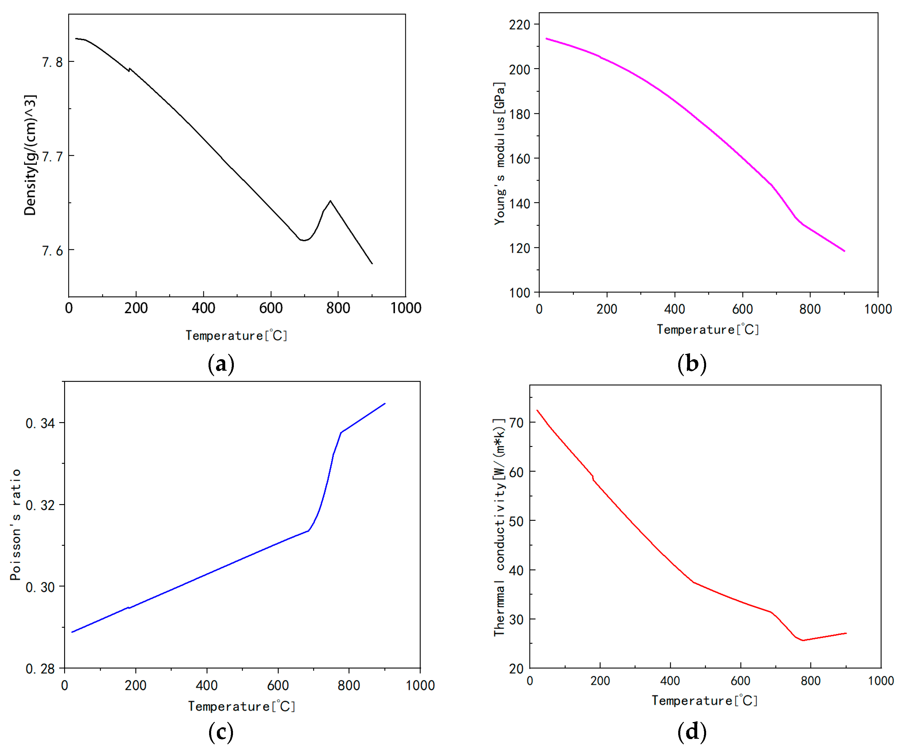
3.1. Stator Guide 18CrNiMo7-6 Carburizing Steel Composition and Thermal Properties

Figure 1 shows the hydraulic motor stator guide; the manufacturer is Zhenjiang Jinding Gearbox Co., Ltd. (Zhenjiang, China), its material is 18CrNiMo7-6, the surface hardness is 59 HRC, the diameter is 264 mm, and its chemical composition and mass fraction are determined as shown in Table 2. The thermophysical properties of the material—density, Young’s modulus, Poisson’s ratio, and thermal conductivity—are needed for heat treatment simulation. At different temperatures, some physical properties of the material will change, which requires the establishment of certain functional relationships to ensure the correctness of the heat treatment simulation. This paper uses JmatPro7.0 software to calculate the thermal properties of the 18CrNiMo7-6 material at different temperatures, as shown in Figure 2.
As shown in Figure 3, the TTT curves were calculated using JMatPro software [34]. The bainite (0.1%) curve represents the transformation curve of bainite in 18CrNiMo7-6 steel, i.e., after holding the steel at a certain temperature for a certain time, the austenite starts to transform to bainite. The bainite (99.9%) curve represents the end transformation curve of 18CrNiMo7-6 steel; i.e., after holding the steel at a certain temperature for a certain period of time, austenite is completely transformed to bainite. The same is true for F (0.01%), P (0.01%), and P (99.9%). MS is the martensitic transformation temperature of 355 °C. The bainite (99.9%) curve represents the transformation of 18CrNiMo7-6 steel to bainite.

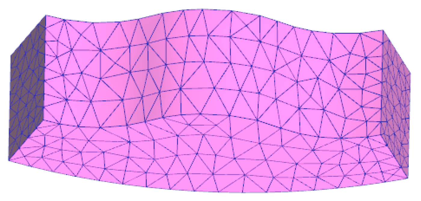
3.2. Finite Element Model

The thermal property parameters of 18CrNiMo7-6 material calculated by JmatPro software were imported into the heat treatment software DEFORM11.0. The heat treatment process of 18CrNiMo7-6 steel for the stator guide is carburizing, quenching, and tempering, and the key parameters of the heat treatment process are shown in Table 3. When carburizing, the stator guide is heated up to 920 °C, and the carbon concentration is kept at 1.1% for 4 h, and then quenching and tempering are carried out.
As shown in Figure 4, within the curve of the radial piston motor structure for the 8-acting 10 plunger, the stator guide has a periodicity. In order to calculate the convenience of taking part of the guide in SolidWorks to establish a three-dimensional geometric model, the three-dimensional model is saved in a format for X-T, imported into DEFORM, and divided into meshes, as shown in Figure 5 for the heat treatment model.

3.3. Numerical Simulation and Experimental Validation of the Carburizing Process for the Stator Guide

Figure 6a is the hardness distribution cloud diagram of the stator guide after carburizing heat treatment, which is one-eighth of the stator guide with a diameter of 264 mm and a height of 32 mm. The type of hardness is Rockwell hardness. It can be seen that the hardness of the surface carburized layer is 59.0 HRC, and the hardness of the core is 43.3 HRC. Since the surface carburized layer has a high martensite content, and the core has less martensite, the hardness decreases from the surface to the core in turn.
This paper adopts the well-type gas heat treatment furnace produced by Wuhan Jiahua Furnace Co., Ltd., Wuhan, China, with a power of 78 kW, and the operating system is the German Stange system. The carburizing conditions of the stator guide are shown in Table 3. In order to verify the hardness of the carburized layer of the stator guide, the stator guide was sampled and experimented using the HVS-1000AT automatic microscopic Vickers hardness tester. The instrument has a test force range of 0.01~1 kg and a hardness test range of 5–5000 HV, and is highly automated and accurate. The test load used in this paper is 1.0 kg, and the holding time is 15 s. The magnification of the microscope during the measurement is 400×, and the minimum resolution of the measurement indentation is 0.1. In order to study the mechanical properties of the inner surface, the inner surface was cut, sampled, cleaned, ground, and polished before the hardness test. As shown in Figure 6b, the hardness measurement result at the surface was 59.7 HRC. The average values of the experiments at three different locations were taken as the experimental results and compared with the simulation results. The simulation conditions are the same as the experimental conditions shown in Table 3, in which the simulation fitting curve utilizes the DEFORM point tracking function to take points perpendicular to the carburized layer in order to determine the hardness of different depth layers. As shown in Figure 6c, the error range is within 4.5%, which shows that the heat treatment model meets the requirements.

4. Mechanical Performance Prediction and Parameter Optimization

4.1. Mechanical Property Prediction Based on RBF Neural Network

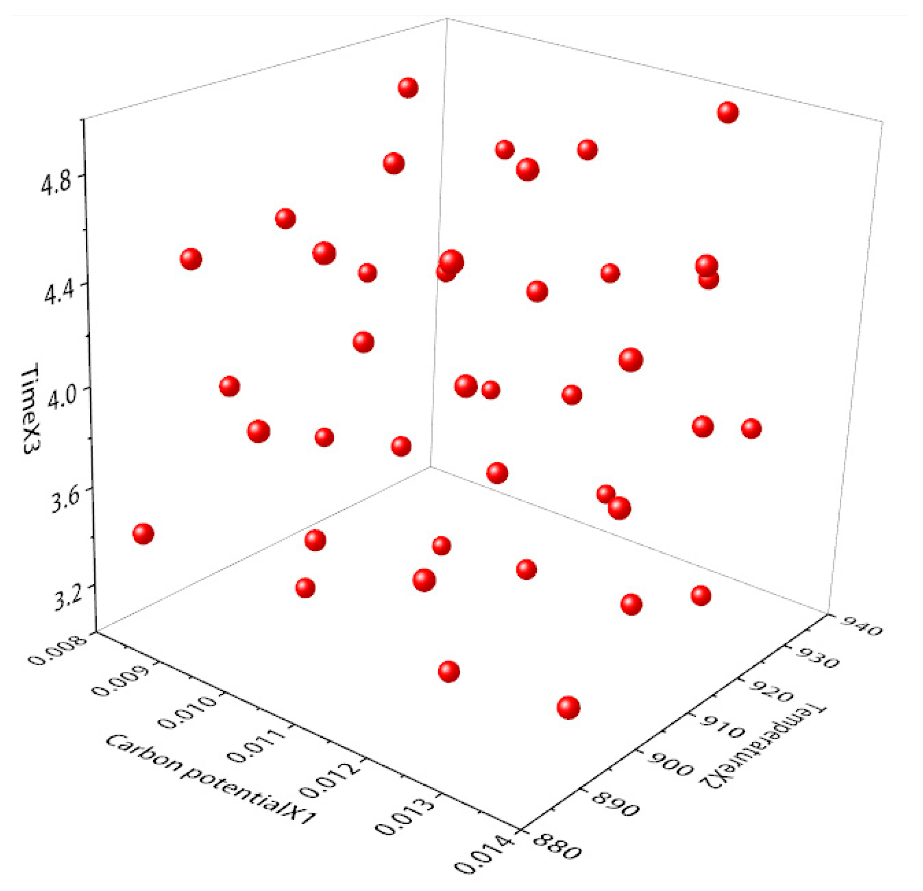
4.1.1. DEFORM-ISIGHT-Based DOE Experimental Design

Design of Experiments is a mathematical and statistical method used to arrange experiments and analyze experimental data [35]. Its main purpose is to obtain ideal experimental results as well as drawing scientific conclusions by rationally arranging experiments with a smaller experimental scale (number of experiments), shorter experimental period, and lower experimental cost. DOE design can not only identify the effects of single factors but also identify the interactive effects of multiple factors, which is an important guarantee for product quality improvement and process improvement.
According to the main parameters in the carburizing process, carburizing carbon potential X1, temperature X2, and time X3 are selected as design variables. The range of values of the variables is defined in the context of the actual situation. The design variables, their initial values, and the set upper and lower limits are shown in Table 4.
This paper establishes an experimental analysis model in Isight2022 software, creates three new design variables, sets up the corresponding variable ranges, and selects the optimal Latin Hypercubic Design method to conduct the test. Optimal Latin hypercubic design has a more uniform distribution of sample points within the design range compared to other test methods, making the approximate model fit more accurate afterwards. In order to ensure a comprehensive analysis, the empirical formula 2(n + 1) × (n + 2) was used to determine the number of samples, where n is the number of variables. Thus, the sample set has the number of samples set to 40, and the final data generated are shown in Table 5. As shown in Figure 7, the sampling points are uniformly distributed in space, with no obvious concentration.
The degree of influence of the design variables on the target values can be visualized and clearly represented using Pareto diagrams. In the Pareto plot, the contribution values produced by the design variables to the output objective are presented in the form of percentages, where the sum is 100%, and the design variables are sorted by their contribution values. As shown in Figure 8, each design variable produces a significant difference in sensitivity to the optimization objective. Figure 8a shows the effect of each variable on the hardness of the carburized layer, and Figure 8b shows the effect of each variable on the depth of the carburized layer, in which the parameter sensitivities of the carbon potential, temperature, and time are all positive, and the degree of influence is in the following order: carburizing temperature X2 > holding time X3 > carburizing carbon potential X1. The reason for the small influence of carbon potential X1 is that its scale is small and the change in value is not obvious, resulting in low sensitivity.

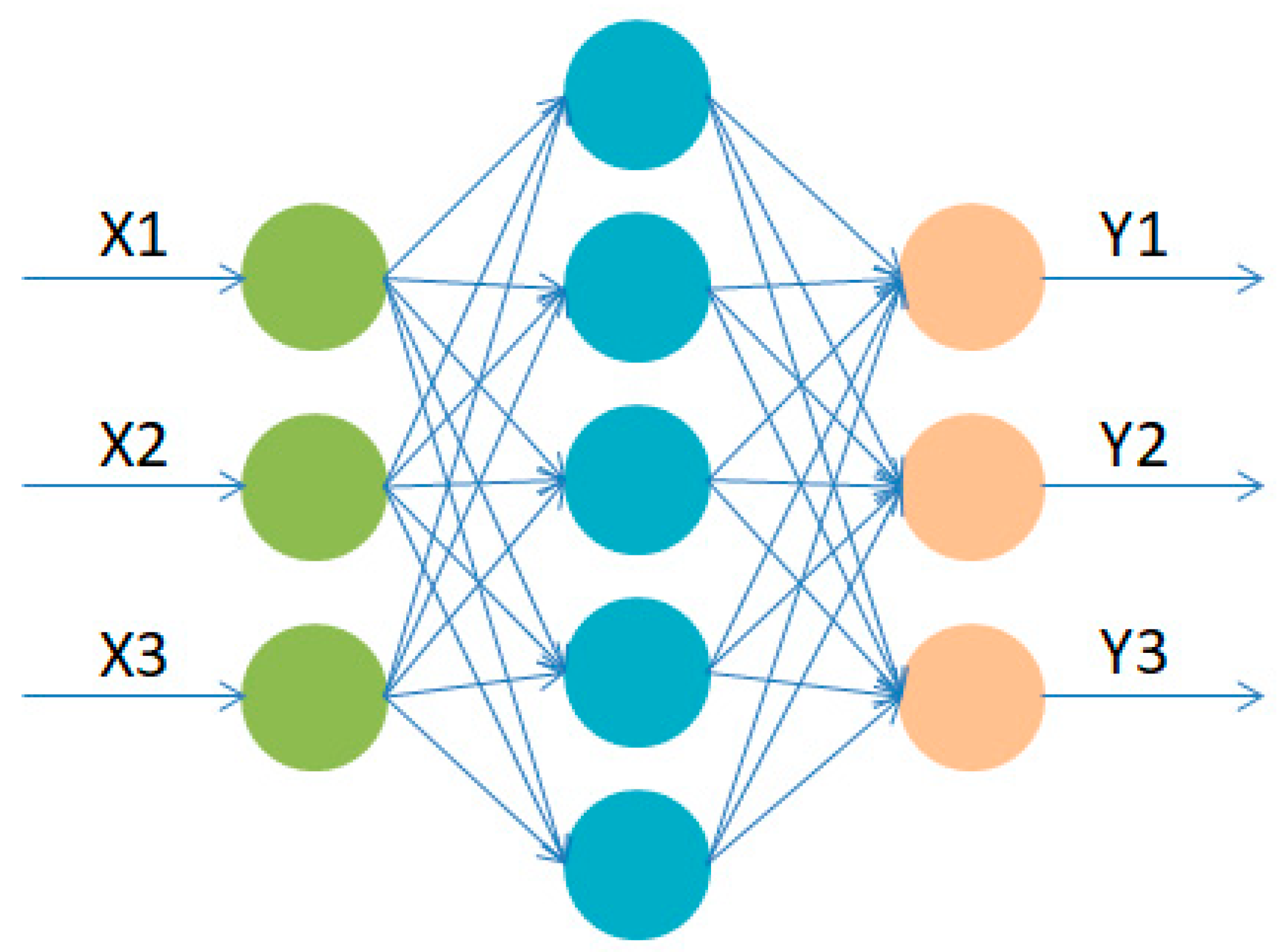
4.1.2. Approximate Modeling Based on RBF Neural Network

RBF neural network [36], i.e., radial basis function neural network, is a kind of artificial neural network based on the radial basis function as the activation function. Due to the local response characteristics of the radial basis function, the RBF neural network has a strong generalization ability and can adapt to complex nonlinear problems; it can approximate any continuous function with arbitrary accuracy, which is especially suitable for solving the classification problem. The training process of the RBF neural network is relatively simple, and the learning convergence speed is fast, which is suitable for large-scale data processing.
To determine the design variables and output response of the model, this paper selects carbon potential X1, temperature X2, and time X3 as the design variables, and hardness Y1, thickness Y2, and deformation Y3 as the response outputs. Among them, the amount of deformation produced by the stator guide in the carburizing process is influenced by carburizing temperature, carburizing time, and carbon potential. The RBF neural network is used to train on the network model, as shown in Figure 9, to establish an agent model between mechanical properties and carburizing process parameters. The 40 groups of data collected by the optimal Latin hypercube are numerically simulated to obtain the response values of the corresponding sample points, and the results are shown in Table 6; 30 groups are used for training and 10 groups are used for validation.
It is found that there is some intrinsic relationship between the design variables and the output response through training. This paper only shows the response relationship between carbon potential and time on hardness and depth of carburization, as shown in Figure 10. Within the design range, as time and carbon potential increase, hardness and depth of carburization also increase.
In order to assess the prediction accuracy of the approximation model, the coefficient of determination R2 is used as the key evaluation index [37]. The coefficient of determination is used to measure the degree of correlation between the two variables or the degree of fit of the regression model, i.e., the model is capable of explaining the percentage of changes in the dependent variable. The value of R2 ranges from 0 to 1, and the closer the value is to 1, the better the model fit. Figure 11 shows the error analysis of the stator guide carburizing simulation approximation model; the R2 values for hardness, thickness, and deformation are 0.94306, 0.90128, and 0.92224, respectively, which all meet the error evaluation standard of 0.9. This result shows that the prediction model based on the RBF neural network has high accuracy, can be used to replace the finite element model for computation, and is capable of the subsequent multi-objective optimization.

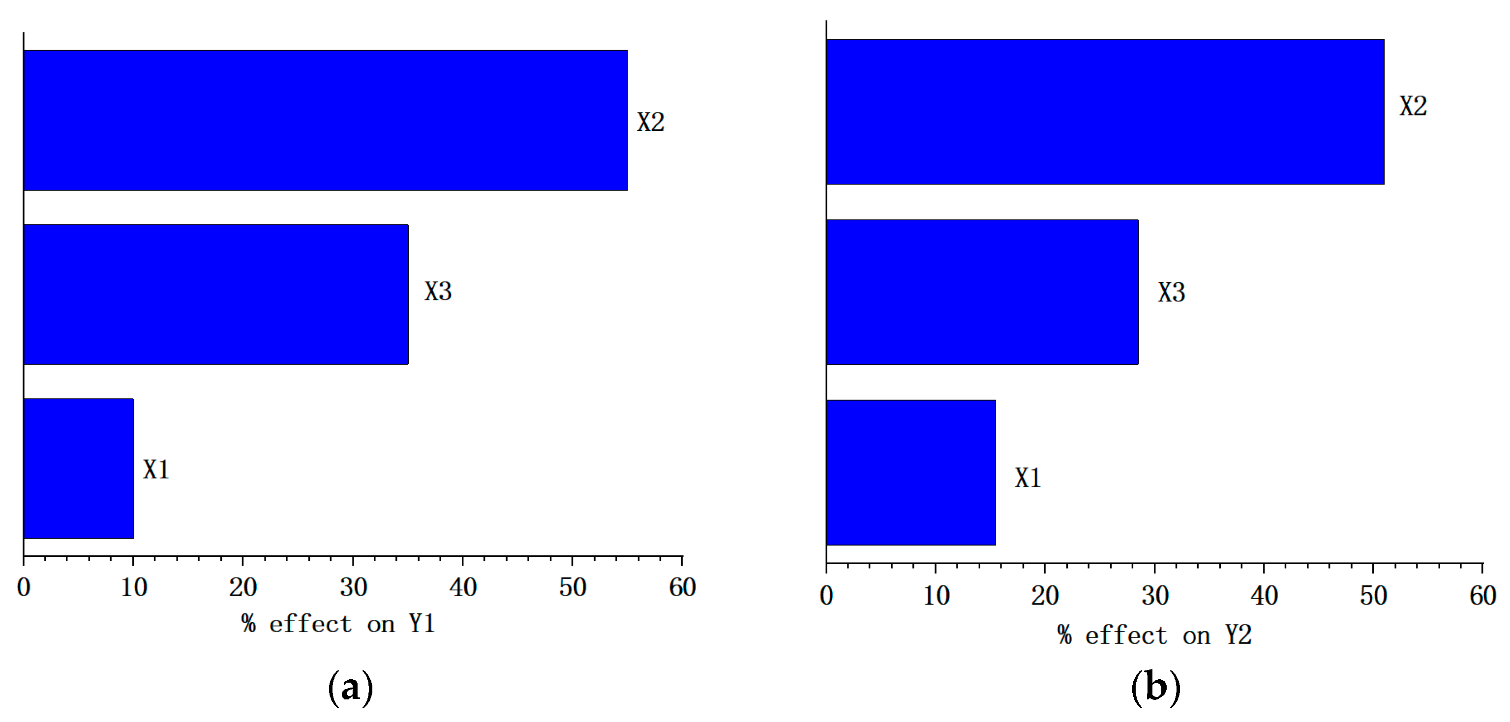
4.1.3. Optimization of Stator Guide Carburizing Process Parameters for Hydraulic Motor Based on NSGA-II Algorithm

The basic principle of multi-objective optimal design lies in the construction of a mathematical model describing the actual problem, which mainly includes the design variables, constraints, and objective function; of these, objective function is the core of the optimal design and represents the performance target pursued by the design. In this paper, carburizing hardness, depth, and workpiece deformation are the main indicators for judging the effect of the carburizing process [38]. In order to make the stator guide surface mechanical properties meet the requirements of the carburized layer which has a minimum depth, the depth of the carburized layer needs to reach 1.2 mm, and the surface hardness should reach 61 HRC. Thus, an approximation model is established based on the RBF neural network, with carburizing hardness, depth, and deformation as the objective function, and carburizing carbon potential X1, temperature X2, and time X3 as the design variables. The multi-objective optimization model based on the above conditions is shown in Equations (13) and (14).
A multi-objective optimization algorithm is used to solve the RBF neural network approximation model to obtain the optimization scheme of the carburizing process. As shown in Figure 12, the NSGA-II algorithm went through multiple measurement iterations to obtain the optimization history of surface hardness, carburizing depth, and workpiece deformation. By analyzing the optimization process, it is found that several groups of data meet the requirements, of which the optimal group is selected as an example. When the optimized values of the carburizing parameters are a carbon potential of 1.35%, a temperature of 900 °C, and a time of 4.1 h, the surface hardness is 61.25 HRC, the carburizing thickness is 1.29 mm, and the deformation is 0.31 mm.
Objective . max H a r d n e s s = m a x f 1 ( X 1 , X 2 , X 3 ) max D e p t h = m a x f 2 X 1 , X 2 , X 3 min D e f o r m a t i o n = m a x f 2 X 1 , X 2 , X 3
Subject   to . X 1 [ 0.8 % , 1.4 % ] X 2 [ 880,940 ] X 3 [ 3,5 ] H a r d n e s s 61 D e p t h 1.2 D e f o r m a t i o n 0.32
In order to verify the effectiveness of the algorithm, the carburization parameters in the finite element model were modified to the optimal solution, and the model was re-simulated and analyzed; the simulation results are shown in Figure 13. The simulation results are also compared with the predicted results, as shown in Table 7. It is found that the simulation results are in high agreement with the predicted results, in which the deformation of the workpiece decreases to 0.31 mm under the condition of increasing the surface hardness by 4.1% and the thickness of the carburized layer by 5.1%. Comparison can be made to show that the optimized results based on the RBF neural network and NSGA-II algorithm are better.

5. Conclusions

In this study, based on the numerical model of stator guide carburizing quenching, a finite element model of stator guide carburizing quenching is established, which can predict the surface hardness, deformation, and depth of the carburized layer of the workpiece after carburizing, and the model is experimentally verified. After that, the agent model of surface hardness, deformation, and depth of the carburized layer is constructed by using the RBF neural network. Finally, on the basis of the agent model, a multi-objective optimization algorithm is used to obtain the heat treatment process parameters that meet the requirements of mechanical properties. The conclusions are as follows:
(1)
Using DEFORM software, the stator guide carburizing model was established; it can simulate the carburizing process and predict the indicated hardness, deformation, and depth of the carburized layer of the workpiece after carburizing. By simulating the actual working conditions, the simulation results and experimental results for hardness were compared; the error range is within 4.5%, which verifies the correctness of the establishment of the finite element model.
(2)
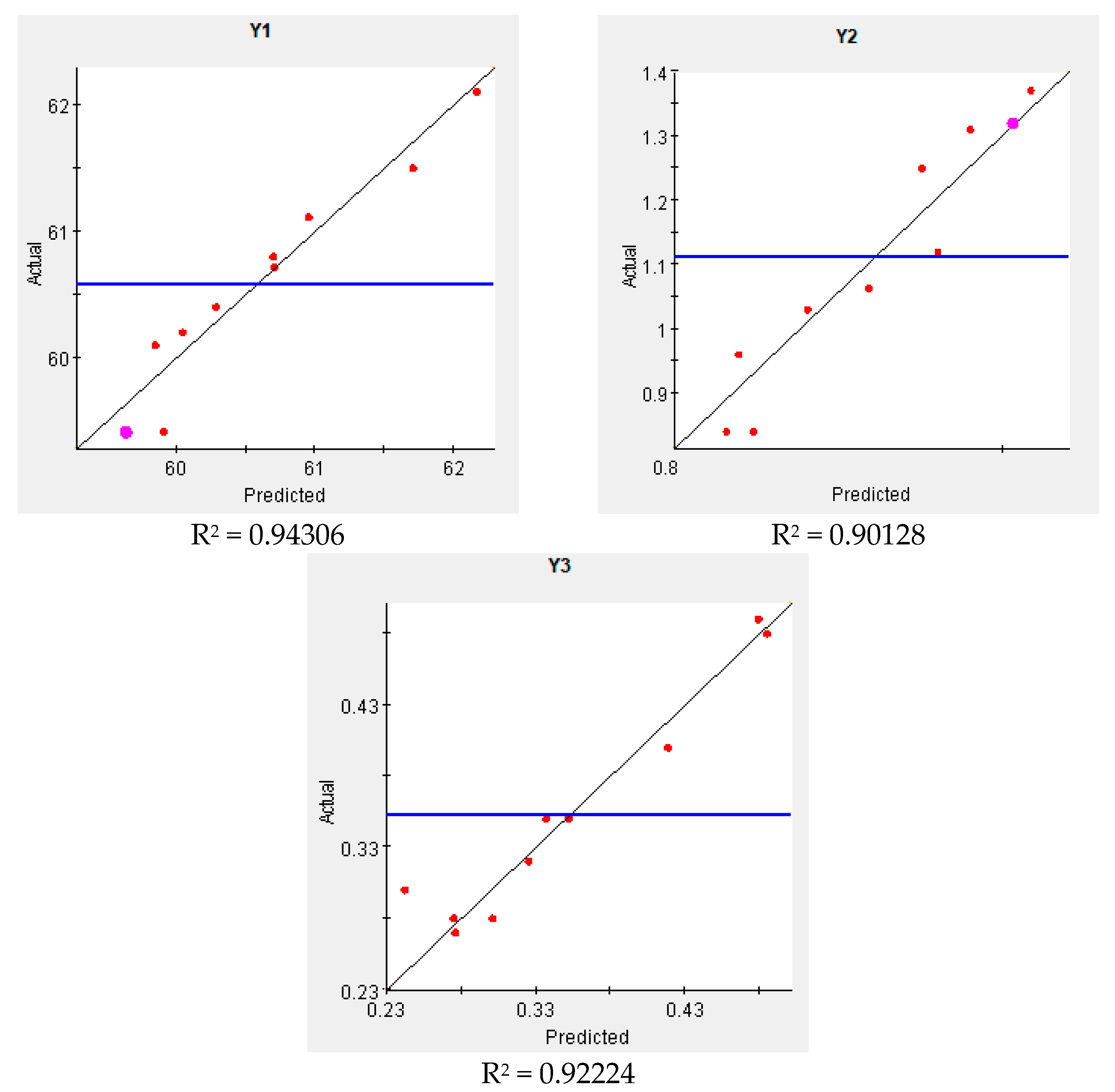
A DOE full factorial test design was carried out for the carburizing process, and carburizing potential, temperature, and time were selected as design variables. The approximate model was established by the RBF neural network, and it was found that the approximate model has high precision and can replace the finite element model analysis and greatly improve the optimization efficiency; the prediction accuracy is greater than 90%.
(3)
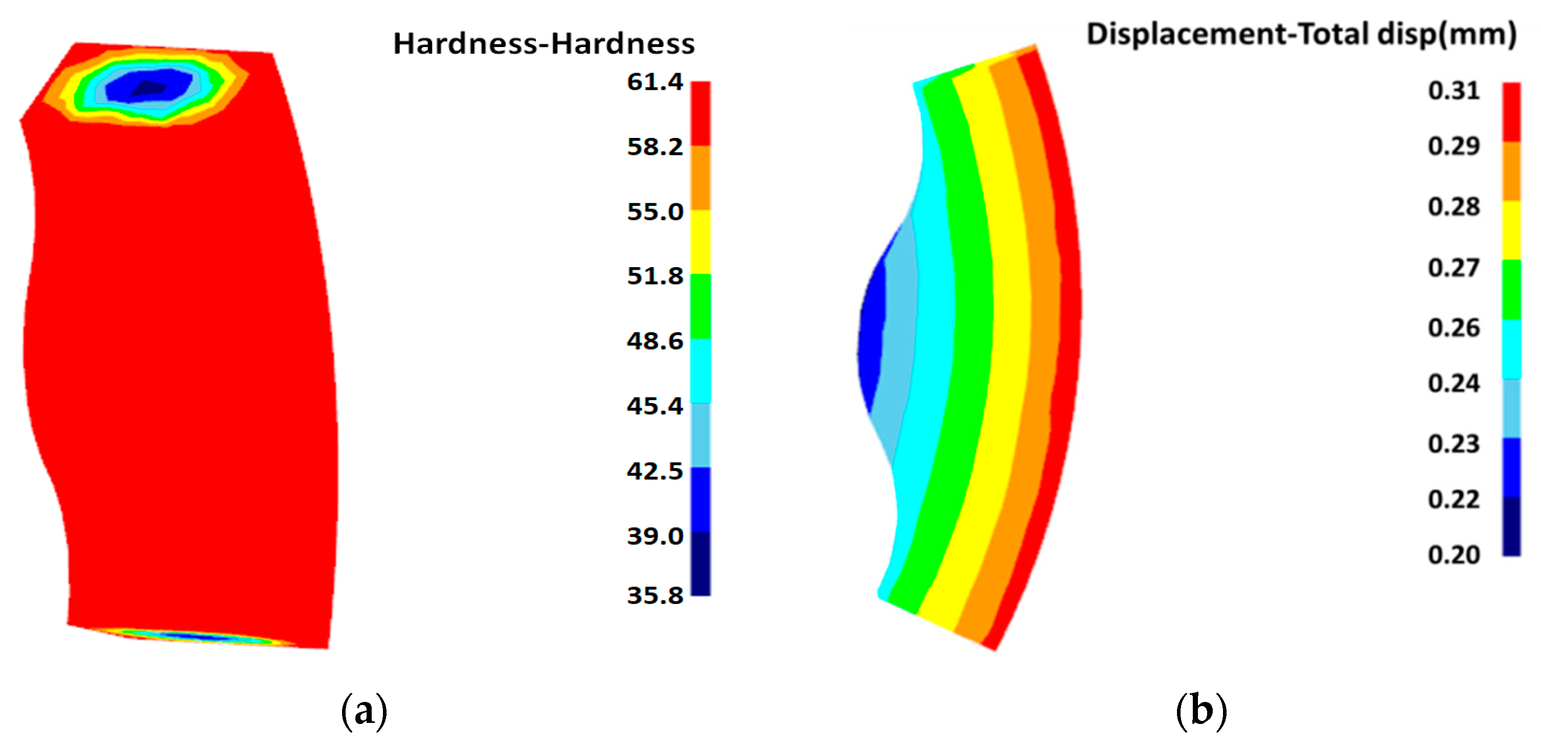
On the basis of the approximation model, the NSGA-II algorithm was used to carry out multi-objective optimization, and the optimized carburization parameters were a carbon potential of 1.35%, a temperature of 900 °C, and a time of 4.1 h. The surface hardness increased from 59 HRC to 61.25 HRC, and the depth of carburization increased from 1.23 mm to 1.29 mm, which is an increase of 4.2% and 5.1%, and at the same time, the amount of deformation decreased to 0.31 mm. Finally, the optimized parameters were substituted into the finite element model, and the simulation results were found to be highly consistent with the optimization results, which verified the correctness of the optimization.

Author Contributions

C.L.: Writing—original draft, Validation, Formal analysis, and Conceptualization. Y.T.: Writing—review and editing, Methodology, and Formal analysis. J.C.: Visualization, Supervision, and Formal analysis. Z.X.: Formal analysis and Data curation. All authors have read and agreed to the published version of the manuscript.

Funding

This work was financially supported by Changzhou Weihai Jingtian Mechanical Equipment Manufacturing Co., Ltd. (BY20231384) and the National Natural Science Foundation of China coded 52305061.

Institutional Review Board Statement

Not applicable.

Informed Consent Statement

Not applicable.

Data Availability Statement

The data presented in this study are available in the article.

Conflicts of Interest

The authors declare no conflicts of interest.

References

  1. Liu, C.; Wei, X.; Yi, Z.; Li, Z.; Zhu, C.; Ma, Z. Strength Analysis and Structure Optimization of the Crankshaft of an Opposed-Power Reciprocating Pump. Machines 2023, 11, 123. [Google Scholar] [CrossRef]
  2. Liu, Z.-J.; Zhao, Y.-C.; Gan, Z.-Q.; Hui, D.-L. Driving shaft fatigue optimization design of Ω type profile twin-screw pumps. J. Mech. Sci. Technol. 2018, 32, 5089–5096. [Google Scholar] [CrossRef]
  3. Zhu, J.; Cao, J.; Guo, W. Three-dimensional fatigue crack growth based method for fatigue reliability of metallic materials. Int. J. Fatigue 2023, 173, 107697. [Google Scholar] [CrossRef]
  4. Klevtsov, G.V.; Valiev, R.Z.; Klevtsova, N.y.A.; Tyurkov, M.N.; Pigaleva, I.N.; Aksenov, D.A. Fracture Kinetics and Mechanisms of Ultrafine-Grained Materials during Fatigue Tests in the Low-Cycle Fatigue Region. Metals 2023, 13, 709. [Google Scholar] [CrossRef]
  5. Goo, B.-C. Effect of post-weld heat treatment on the fatigue behavior of medium-strength carbon steel weldments. Metals 2021, 11, 1700. [Google Scholar] [CrossRef]
  6. Réger, M.; Horváth, R.; Széll, A.; Réti, T.; Gonda, V.; Felde, I. The relationship between surface and in-depth hardness for the nitrocarburizing treatment process. Metals 2021, 11, 812. [Google Scholar] [CrossRef]
  7. Wolff, S.J.; Gan, Z.; Lin, S.; Bennett, J.L.; Yan, W.; Hyatt, G.; Ehmann, K.F.; Wagner, G.J.; Liu, W.K.; Cao, J. Experimentally validated predictions of thermal history and microhardness in laser-deposited Inconel 718 on carbon steel. Addit. Manuf. 2019, 27, 540–551. [Google Scholar] [CrossRef]
  8. Hu, X.; Li, J.; Wang, Z.; Wang, J. A microstructure-informatic strategy for Vickers hardness forecast of austenitic steels from experimental data. Mater. Des. 2021, 201, 109497. [Google Scholar] [CrossRef]
  9. Guo, Y.; Liu, M.; Yan, Y. Hardness prediction of grind-hardening layer based on integrated approach of finite element and cellular automata. Materials 2021, 14, 5651. [Google Scholar] [CrossRef]
  10. Ko, D.-H.; Ko, D.-C.; Kim, B.-M. Novel method for predicting hardness distribution of hot-stamped part using Fe-simulation coupled with quench factor analysis. Metall. Mater. Trans. B 2015, 46, 2072–2083. [Google Scholar] [CrossRef]
  11. Zhang, W.; Chen, X.; Yang, C.; Wang, X.; Zhang, Y.; Li, Y.; Xue, H.; Zheng, Z. A multiphysics model for predicting microstructure changes and microhardness of machined AerMet100 steel. Materials 2022, 15, 4395. [Google Scholar] [CrossRef] [PubMed]
  12. Liu, S.; Hong, K.-M.; Katinas, C.; Shin, Y.C. Multiphysics modeling of phase transformation and microhardness evolution in laser direct deposited Ti6Al4V. J. Manuf. Process. 2019, 45, 579–587. [Google Scholar] [CrossRef]
  13. Umemoto, M.; Ohtsuka, H. Mechanical Properties of Cementite. ISIJ Int. 2022, 62, 1313–1333. [Google Scholar] [CrossRef]
  14. Savrai, R.A.; Skorynina, P.A.; Makarov, A.V.; Osintseva, A.L. Effect of Liquid Carburizing at Lowered Temperature on the Micromechanical Characteristics of Metastable Austenitic Steel. Phys. Met. Metallogr. 2020, 121, 1015–1020. [Google Scholar] [CrossRef]
  15. Deng, Y.; Qiao, L.; Zhu, J.; Yang, B. Mechanical Performance and Microstructure Prediction of Hypereutectoid Rail Steels Based on BP Neural Networks. IEEE Access 2020, 8, 41905–41912. [Google Scholar] [CrossRef]
  16. Wei, Y.; Yu, X.; Wang, S.; Shen, X.; Zhao, W.; Su, Y.; Yang, Y.; Feng, X. Effect of Short-Time Carburizing Treatment on Microstructure and Mechanical Properties of M50 Steel. Met. Mater. Int. 2023, 29, 1586–1595. [Google Scholar] [CrossRef]
  17. Yan, Y.; Liu, K.; Luo, Z.; Wang, M.; Wang, X. Effect of cryogenic treatment on microstructure, mechanical properties and distortion of carburized gear steels. Metals 2021, 11, 1940. [Google Scholar] [CrossRef]
  18. Fang, D.; Lu, J.; Dou, H.; Zhou, Z.; Yan, J.; Li, Y.; He, Y. Effect of Post-Plasma Nitrocarburized Treatment on Mechanical Properties of Carburized and Quenched 18Cr2Ni4WA Steel. Lubricants 2024, 12, 153. [Google Scholar] [CrossRef]
  19. Long, J.B.; Li, X.B.; Zhong, Y.C.; Peng, D. Application of BP Neural Networks on the Thickness Prediction of Sherardizing Coating. Trans. Indian Inst. Met. 2019, 72, 2443–2448. [Google Scholar] [CrossRef]
  20. Sirin, S.Y.; Nal, M. Artificial neural network approach to predict ion nitrided case depth and surface hardness of AISI 4340 steel. Mater. Test. 2019, 61, 567–572. [Google Scholar] [CrossRef]
  21. Wang, X.; Li, D.; Li, P. Analysis and Optimization of Carburizing–Quenching Distortion on Locomotive Gear Ring. JOM 2023, 75, 2441–2450. [Google Scholar] [CrossRef]
  22. Zhang, X.; Tang, J.-y.; Zhang, X.-r. An optimized hardness model for carburizing-quenching of low carbon alloy steel. J. Cent. South Univ. 2017, 24, 9–16. [Google Scholar] [CrossRef]
  23. Wang, H.; Wang, B.; Wang, Z.; Tian, Y.; Misra, R. Optimizing the low-pressure carburizing process of 16Cr3NiWMoVNbE gear steel. J. Mater. Sci. Technol. 2019, 35, 1218–1227. [Google Scholar] [CrossRef]
  24. Yang, Z.; Wei, J.; Liu, T.; Liu, S.; Fang, D.; Li, Z. Influence of carbon layer hardness characteristics on RCF performance of carburized bearing steel and optimization of heat treatment process. Eng. Fail. Anal. 2024, 160, 108164. [Google Scholar] [CrossRef]
  25. Miao, S.; Ju, D.-Y.; Chen, Y.; Liu, Y.-q. Optimization based on orthogonal experiment design and numerical simulation for carburizing quenching process of helical gear. Mater. Perform. Charact. 2019, 8, 66–79. [Google Scholar] [CrossRef]
  26. Luo, A.; Lei, M.; Song, W.; Wan, M.; Chen, G.; Qu, Z. Enhanced Friction and Wear Performance of 297A-Hybridsteel Carburized Layer through Pre-tempering Optimization. J. Mater. Eng. Perform. 2024, 1–9. [Google Scholar] [CrossRef]
  27. LSalawu, E.Y.; Adediran, A.A.; Ajayi, O.O.; Inegbenebor, A.O.; Dirisu, J.O. On the analyses of carbon atom diffused into grey cast iron during carburisation process. Sci. Rep. 2022, 12, 18303. [Google Scholar]
  28. Wei, L.; Meng, W.-D.; Sun, L.-C.; Cao, X.-F.; Pu, X.-Y. Measurement and verification of concentration-dependent diffusion coefficient: Ray tracing imagery of diffusion process. Chin. Phys. B 2020, 29, 084206. [Google Scholar] [CrossRef]
  29. Liang, R.; Wang, Z.; Yang, S.; Chen, W. Study on hardness prediction and parameter optimization for carburizing and quenching: An approach based on FEM, ANN and GA. Mater. Res. Express 2021, 8, 116501. [Google Scholar] [CrossRef]
  30. Wen, G.; Du, C. Research on Key Technology of Finite Element Simulation of 12CrNi3 Helical Gear Carburizing and Quenching Process. New Technol. New Process 2019, 06, 20–26. [Google Scholar]
  31. Sugianto, A.; Narazaki, M.; Kogawara, M.; Shirayori, A.; Kim, S.-Y.; Kubota, S. Numerical simulation and experimental verification of carburizing-quenching process of SCr420H steel helical gear. J. Mater. Process. Technol. 2009, 209, 3597–3609. [Google Scholar] [CrossRef]
  32. Tong, D.; Gu, J.; Yang, F. Numerical simulation on induction heat treatment process of a shaft part: Involving induction hardening and tempering. J. Mater. Process. Technol. 2018, 262, 277–289. [Google Scholar] [CrossRef]
  33. Khan, D.; Gautham, B. Integrated modeling of carburizing-quenching-tempering of steel gears for an ICME framework. Integr. Mater. Manuf. Innov. 2018, 7, 28–41. [Google Scholar] [CrossRef]
  34. Zhang, Y.; Wang, T.; Fu, J.; Sun, H.; Li, J.; Liu, H. Research on microstructure evolution and mechanical properties of steering shaft teeth after pre-heat treatment and carburizing-quenching processes. In Proceedings of the 2021 7th International Forum on Manufacturing Technology and Engineering Materials (IFEMMT 2021), Dali, China, 18–20 June 2021; IOP Publishing: Bristol, UK, 2021; Volume 1965, p. 012051. [Google Scholar]
  35. Wang, Z.; Feng, Y.; Yang, Y.; Wang, J.; Xu, S.; Qin, J. Multi-objective optimization of rectangular cooling channel design using Design of Experiments (DOE). Appl. Therm. Eng. 2024, 242, 122507. [Google Scholar] [CrossRef]
  36. Guo, S.; Li, C.; Shi, J.; Luan, F.; Song, X. Effect of quenching media and tempering temperature on fatigue property and fatigue life estimation based on RBF neural network of 0.44% carbon steel. Mech. Sci. 2019, 10, 273–286. [Google Scholar] [CrossRef]
  37. Piepho, H.P. An adjusted coefficient of determination (R2) for generalized linear mixed models in one go. Biom. J. 2023, 65, 2200290. [Google Scholar] [CrossRef]
  38. Liu, S.; Yang, Z.; Liu, T.; Li, Z.; Cong, T. Effect of Case Depth and Hardness Distribution on the Rolling Contact Fatigue Performance of G20CrNi2MoA Carburized Steel. Steel Res. Int. 2024, 95, 2300875. [Google Scholar] [CrossRef]
Figure 1. Hydraulic motor stator guide.
Coatings 14 01369 g001
Figure 2. Thermal property parameters of 18CrNiMo7-6 steel at different temperatures. (a) Density, (b) Young’s modulus, (c) Poisson’s ratio, and (d) thermal conductivity.
Coatings 14 01369 g002
Figure 3. 18CrNiMo7-6 TTT curve.
Coatings 14 01369 g003
Figure 4. Stator guide structure.
Coatings 14 01369 g004
Figure 5. Heat treatment model.
Coatings 14 01369 g005
Figure 6. Stator guide carburizing simulation and hardness test. (a) Hardness simulation. (b) Hardness test results. (c) Comparison of simulation and experiment.
Coatings 14 01369 g006
Figure 7. Spatial distribution of samples.
Coatings 14 01369 g007
Figure 8. Sensitivity analysis of the variables. (a) the effect of each variable on the hardness of the carburized layer. (b) the effect of each variable on the depth of the carburized layer.
Coatings 14 01369 g008
Figure 9. RBF neural network model.
Coatings 14 01369 g009
Figure 10. Approximate model of carburizing hardness and depth.
Coatings 14 01369 g010
Figure 11. Approximate model error analysis.
Coatings 14 01369 g011
Figure 12. Stator guide carburizing process optimization history. (a) Surface hardness, (b) carburizing depth, and (c) deformation.
Coatings 14 01369 g012
Figure 13. Simulation results after optimization of carburizing process. (a) Hardness simulation and (b) deformation.
Coatings 14 01369 g013
Table 1. Heat transfer coefficients for heating and carburizing processes.
Heat Treatment StateHeat Transfer Coefficient [J/(S∙mm∙°C)]
heating stage0.1
carburizing stage0.05
Table 2. Chemical composition of 18CrNiMo7-6 steel (wt%).
CSiMnSPCrNiMoFe
0.210.340.720.0040.011.581.40.26Bal.
Table 3. Heat treatment process parameters of stator guide.
Heat TreatmentProcessT [°C]Time [s]Carbon Potential [%]Type of Cooling
CarburizationIntensive carburizing93014,4001.2-
QuenchingOil quenching2514400.6Oil cooling
TemperingLow tempering180720-Air cooling
Table 4. Stator guide carburizing process design variables.
Variable NameLower ValueInitial ValueUpper Value
Carbon Potential X10.8%1.1%1.4%
Temperature X2880 °C920 °C940 °C
Time X33 h4 h5 h
Table 5. Simulation test table.
Test NumberCarbon Potential X1Temperature X2/[°C]Time X3/[h]
10.954923.083
20.815916.923.41
30.923901.543.051
41.323909.233.359
51.031890.773.513
60.862881.543.462
71.246932.314.333
81906.154.795
91.123924.623.821
101.092929.234.744
111.262930.775
121.154912.314.385
131.185895.383.103
141.169904.623.769
150.985910.773.615
161.077886.154.692
170.831907.694.436
181.338918.463.974
191.308926.153.154
201.0159004.179
211.108935.383.256
221.231884.623.667
230.877887.694.487
241.4893.854.538
251.262883.084.846
260.8926.154.026
271.2903.084.949
280.9699204.231
290.846896.923.872
301.138915.383.205
310.892921.544.897
321.354913.854.641
331.369898.463.923
341.0629404.128
350.938933.853.564
361.292936.923.718
371.215892.314.282
381.385889.233.308
391.0468804.077
400.908938.464.538
Table 6. Sample data points.
Test
Number
Carbon Potential
X1
Temperature
X2/[°C]
Time
X3/[h]
Hardness
Y1/[HRC]
Carburizing Depth Y2/[mm]Deformation Y3/[mm]
1923.08359.50.950.290.954
2916.923.4160.41.070.350.815
3901.543.05158.60.780.250.923
4909.233.35960.21.070.341.323
5890.773.51358.50.830.271.031
6881.543.46258.30.840.250.862
7932.314.33361.71.290.421.246
8906.154.79560.41.120.331
9924.623.82161.21.280.371.123
10929.234.74461.61.30.441.092
11930.77561.81.310.451.262
12912.314.38560.51.130.361.154
13895.383.10358.80.810.271.185
14904.623.76960.11.090.341.169
15910.773.61560.21.080.350.985
16886.154.692601.120.321.077
17907.694.43660.31.140.350.831
18918.463.97460.81.040.381.338
19926.153.15459.70.980.281.308
209004.17960.11.040.321.015
21935.383.25661.51.250.41.108
22884.623.66758.60.840.251.231
23887.694.48758.70.880.260.877
24893.854.53858.90.870.281.4
25883.084.84658.80.880.271.262
26926.154.026601.060.320.8
27903.084.94960.31.060.351.2
289204.23161.11.210.370.969
29896.923.87258.60.820.260.846
30915.383.20560.51.060.361.138
31921.544.89761.21.250.380.892
32913.854.64160.41.140.361.354
33898.463.923601.040.311.369
349404.12862.11.320.491.062
35933.853.56461.51.270.410.938
36936.923.71861.81.280.451.292
37892.314.282590.880.321.215
38889.233.30858.80.840.311.385
398804.07758.40.80.31.046
40938.464.538621.30.480.908
Table 7. Comparison of results before and after optimization.
Type of ResultCarbon PotentialTemperature/°CTime/hSurface Hardness/HRCCarburizing Depth/mmDeformation/mm
Preliminary design1.1920459.01.230.39
Optimized forecasting1.359004.161.251.290.31
Simulation verification1.359004.161.41.280.30
Disclaimer/Publisher’s Note: The statements, opinions and data contained in all publications are solely those of the individual author(s) and contributor(s) and not of MDPI and/or the editor(s). MDPI and/or the editor(s) disclaim responsibility for any injury to people or property resulting from any ideas, methods, instructions or products referred to in the content.

