Abstract
In this paper, 4 mm thick 7075 aluminum alloy was utilized for conducting laser-MIG hybrid welding tests to investigate the correlation between the dynamic behavior of keyholes and process-induced porosity. Additionally, the generation and inhibition mechanisms of process porosity were elucidated. Utilizing a high-speed camera test system of our own design, the formation position and movement characteristics of keyholes in the molten pool under different welding parameters were captured using a “sandwich” method. The dynamic behavior of keyholes during the hybrid welding process was analyzed, and the porosity of each welded joint was quantified, revealing an intrinsic relationship between keyhole dynamics and aluminum alloy laser-MIG hybrid welding porosity. The findings indicate that variations in the defocusing amount can influence both the morphology and stability of keyholes in the molten pool, consequently impacting welding porosity. The dynamic behavior of keyholes under different defocusing amounts can be categorized into five types: no keyhole formation, collapse of the keyhole root, complete instability of the keyhole, instability of the keyhole root, and stability of the keyhole. At a defocus of +12 mm, stable keyholes were observed, and no defects in the welded joints were identified.
1. Introduction
Aluminum alloys, with their low melting point, low density, easy processing, high specific strength, and excellent corrosion resistance, have become the preferred material for the development of lightweight products. They are widely used in automobiles, rail transit, aerospace, and other fields. laser-MIG hybrid welding technology combines laser and arc heat sources, offering advantages such as high welding speed, high efficiency, low heat input, and minimal workpiece deformation after welding. However, the complex welding parameters and high sensitivity to welding porosity in aluminum alloy laser-MIG hybrid welding limit its widespread application. In the 1980s, British scholar M. Teen first proposed laser-arc hybrid welding technology [1]. Since then, as an emerging material joining technology, it has been widely utilized in high-end manufacturing industries such as automobiles, aircraft, and rail transit due to its advantages of high welding adaptability and efficiency [2,3,4]. laser-MIG hybrid welding integrates laser welding and MIG welding, with the two heat sources superimposed and mutually influencing each other, resulting in a complex coupling effect. This approach not only leverages the advantages of both laser welding and MIG welding but also effectively compensates for their respective shortcomings. Reputable researchers all over the world have conducted extensive studies on laser-MIG hybrid welding technology since its inception. P. Leo et al. [5] investigated the impact of the proportions of laser and arc heat sources on the microstructural properties of laser-MIG-welded aluminum alloy joints. The findings indicate that the ratio of the laser heat source to the arc heat source significantly influences the macroscopic formation of welds, grain size, porosity, and magnesium burning loss in joints. In addition, it was found [6] that post-welding heat treatment can reduce the segregation of the element Mg, and the microhardness and tensile strength of the fusion zone can be increased when the heat treatment temperature is 350 °C. Aluminum alloys have physical properties such as high reflectivity and large linear expansion coefficients, which have a great impact on the formation of welds, the generation of welding defects, and the mechanical properties of joints [7,8].
Porosity is the predominant welding defect in laser-MIG hybrid welding of aluminum alloys and represents a critical challenge in the welding process. Its presence leads to a reduction in the effective cross-sectional area of welded joints, induces stress concentration, and has an impact on the mechanical properties and service performance of welded joints [9]. The formation of porosity is mainly affected by three factors: the solidification rate of liquid metal in the molten pool, the presence of hydrogen, and the stability of the keyhole. Domestic and foreign scholars have classified aluminum alloy welding porosity into “metallurgical” and “process” porosity [10]. The main reason for the formation of “metallurgical” porosity is that during the solidification process of hydrogen in the molten pool, its solubility decreases sharply with the decrease in temperature, forming pores with sizes of 50–200 μm, also known as hydrogen pores. Such pores are spherical, with small pore size and smooth inner walls, and can be eliminated by cleaning before welding and adjusting the protective atmosphere [11].
The main reason for “process” porosity is the instability of the keyhole during the welding process, also known as “keyhole” porosity. The shape of such pores is irregular, the apertures are large, and the inner walls are rough, which seriously affects the mechanical properties of the joint [12,13,14]. Huang et al. [15] conducted laser-MIG hybrid welding of 5083 aluminum alloy with the laser in front and the arc in front, respectively, and studied the influence of the sequence of laser and arc on the stability of the welding process and the mechanical properties of the joint. The results showed that the laser-arc hybrid welding (LAHW) mode had a more diffuse arc and a more stable keyhole, which was conducive to the escape of bubbles from the molten pool. Compared with the arc–laser hybrid welding (ALHW) mode, the porosity in the joint was reduced. The mechanical properties of the welded joints obtained from LAHW were also better, and the tensile strength could reach 90.3% of that of the base material.
Xu Guoxiang et al. [16,17] of Jiangsu University of Science and Technology established a three-dimensional model that can directly calculate the dynamic behavior of keyholes and the formation of process porosity after considering many factors such as joint geometric characteristics, droplet transition, molten pool flow, and heat source mode, and they studied the formation process of keyhole porosity in laser-MIG hybrid welding of aluminum alloy material. The results showed that the laser beam dissolved the liquid metal in the molten pool on the surface of the test plate to form a keyhole, and the stable keyhole could provide a “channel” for the bubble to escape, which was conducive to the escape of the bubble from the molten pool. The root of the unstable keyhole was stressed unevenly, the wall of the keyhole was easy to collapse, and the liquid metal of the molten pool was backfilled, preventing the escape of bubbles at the bottom of the keyhole. However, the molten pool created during welding flowed clockwise under the action of the MIG arc’s force, and the unescaped bubbles at the bottom of the molten pool were carried by the fluid to the rear of the molten pool to form pores.
Simulation technology must also be based on the actual motion of the keyhole in the molten pool to establish a correct three-dimensional model. In addition, due to many factors such as changes in temperature and humidity during welding and the actual power of laser irradiation on the workpiece surface, the results obtained through simulation technology also have certain deviations from the actual results [18,19]. To accurately observe the dynamic behavior of keyholes in the molten pool, Matsunawa and Miyagi et al. [20,21,22] of Osaka University successfully obtained dynamic images of keyholes in the molten pool during laser welding of an aluminum alloy through X-Ray synchrotron radiation technology. However, the application of X-Ray synchrotron radiation technology is limited by its high cost, complex operation, and unclear image acquisition. Researchers from Hunan University [23,24,25,26] designed a “sandwich” welding specimen based on high-speed camera technology to observe the dynamic behavior of keyholes in the molten pool. The specimen is composed of 304 stainless steel and GG17 quartz glass. The laser beam welds the metal along the bonding line, and the dynamic behavior of the keyhole in the welding process is captured by a high-speed camera through the quartz glass.
Therefore, in order to analyze the porosity suppression mechanism of the laser-MIG hybrid welding process for an aluminum alloy, a laser-MIG hybrid welding test of 7075 aluminum alloy was carried out under different defocus quantities, and the porosity of each welded joint was calculated. A high-speed camera test system was designed and built, and the formation position and movement characteristics of keyholes in the molten pool under different defocusing amounts were captured by the “sandwich” method. The dynamic behavior of keyholes in the hybrid welding process was analyzed, and the interrelation between the dynamic behavior of keyholes and stomata in an aluminum alloy during the laser-MIG hybrid welding process was expounded upon.
2. Experimental Procedure
2.1. Hybrid Welding System
The laser-MIG hybrid welding test equipment used in this paper is shown in Figure 1. The fiber laser is a YLS-10000-SS4 laser produced by IPG Company in the United States (New York, NY, USA); it is paired with the corresponding water-cooling device to stably emit a laser with the set power level. The MIG welding machine is the TPS500i-PLUSE welding machine produced by Fronius Company in Wels, Austria, with the corresponding wire-feeding mechanism and a special graphite wire-feeding tube for the aluminum alloy, which can achieve stable MIG welding. An integrated KUKA six-axis robot and three-axis gantry were used to build the laser-MIG hybrid welding test system, which enables precise welding of complex welding paths and allows the integrated equipment to control the laser power, welding current, welding voltage, and welding speed.
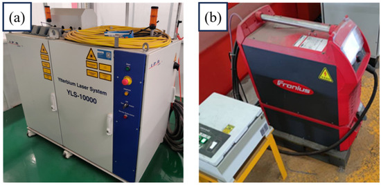
Figure 1.
Hybrid welding system: (a) fiber laser; (b) Fronius welding machine.
The base material for the test was a 7075-T6 aluminum alloy sheet with a thickness of 6 mm, and the welding wire was ER5356. The chemical composition of each material is shown in Table 1. The test employed the butt-welding method, and the test plate specification was 150 × 100 × 6 mm3.

Table 1.
Chemical composition of the 7075 base material and ER5356 welding wire (wt.%).
Aluminum alloys exposed to the air are prone to an oxidation reaction to produce a dense oxide film; due to the high melting point of the Al2O3 film, the weld will develop a large oxide inclusion and non-fusion deficiency. In this experiment, the pretreatment method of mechanical cleaning was adopted. The specific scheme was as follows: First, the edge of the test plate was machined and cleaned with acetone solution to remove the oil on the surface of the test plate. Then, the area to be welded was carefully polished with sandpaper. Finally, the test board was wiped with silk and anhydrous ethanol before welding to remove dust from the surface of the test board. Welding was performed after the anhydrous ethanol was completely volatilized.
A schematic diagram of laser-MIG hybrid welding is shown in Figure 2. In this process, the keyhole shape is greatly affected by the amount of laser defocus. Therefore, the fixed laser power (P) was set to 3.2 kW, the welding speed (v) was 17 mm/s, the welding current (I) was 120 A, and the distance between the laser and the arc (DLA) was 2 mm. The keyhole shape during the welding process was studied by changing the defocusing amount (∆f).
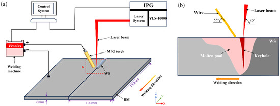
Figure 2.
Schematic diagram of laser-MIG hybrid welding. (a) Welding system diagram; (b) Welding schematic diagram.
2.2. High-Speed Camera System
To observe the change in keyholes’ dynamic behavior in the laser-MIG hybrid welding process for an aluminum alloy and study the influence of keyhole shape change on the porosity in the weld, a high-speed camera test system was established as shown in Figure 3. The Acuteye high-speed camera system consists of a camera lens, a CoaXPress high-speed camera, a CoaXPress coaxial cable, PC memory, and a laser-assisted background light source. Because high-speed photography can only capture the opening and closing behavior of the keyhole in the molten pool formed on the workpiece surface in the welding process, the dynamic change in the keyhole’s shape inside the weld is unknown, and so this approach provides very limited information on the dynamic behavior of the keyhole and the relationship between the keyhole and the porosity of the weld. Therefore, a new “sandwich” method developed by scholars from Hunan University was selected to observe the dynamic changes in the complete shape of keyholes in the welding process with high-speed camera equipment. The so-called “sandwich” method is to use a piece of quartz glass that has a high light transmission rate and can withstand the action of welding heat instead of the 7075 aluminum alloy base material on one side; the two are closely bonded to form a “sandwich” structure from the aluminum alloy and glass sheet, and the light transmission of quartz glass is used to observe the dynamic behavior of the keyhole inside the weld. The quartz glass selected in this paper is 6 mm thick JGS1, and its physical properties are shown in Table 2. Two-thirds of the laser beam focus was preset on the 7075-aluminum alloy test plate, and the other 1/3 was preset on the JGS1 quartz glass, as shown in Figure 4.
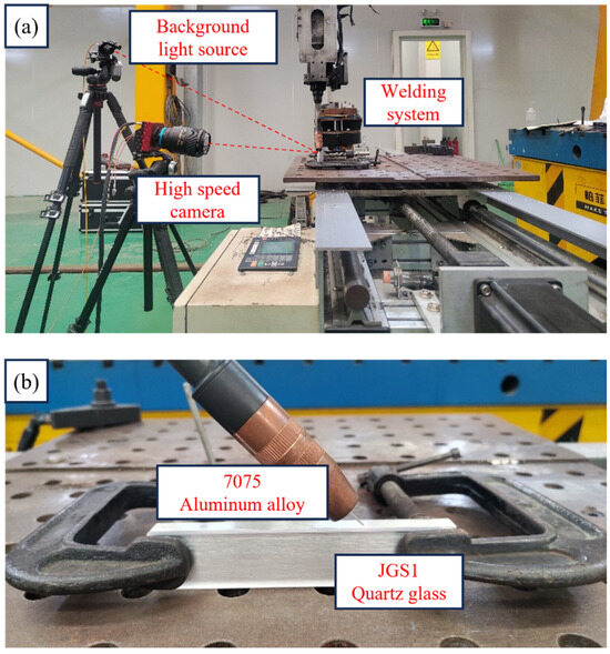
Figure 3.
Experimental system: (a) system platform; (b) local magnification.

Table 2.
Physical properties of JGS1 quartz glass.
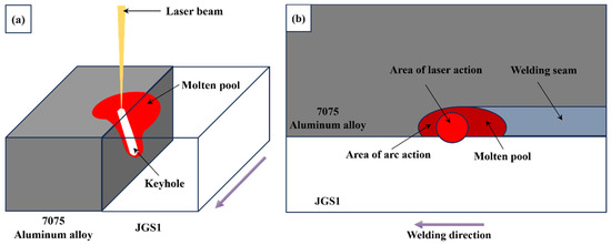
Figure 4.
Diagram of the “sandwich” method. (a) “Sandwich” method for shooting keyholes; (b) preset position of the laser beam focus point.
2.3. Detection and Analysis Equipment
The tensile performance of welded joints was tested using an electronic universal testing machine, as shown in Figure 5a, and the tensile performance test was conducted at room temperature in accordance with GB/T228-2002 “Metallic materials—Tensile testing at ambient temperature” [27]. As shown in Figure 5b, a field emission scanning electron microscope was used to capture the microstructure of various areas in the welded joint, observe the distribution and morphological characteristics of the tensile fracture pores, and determine the types of pores. An XT-3005D X-Ray detector was used for X-Ray detection of weld seams to observe the internal pore distribution of weld seams. The device uses AGFA-C7 film and Lucaid G-39P as the developer.
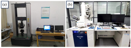
Figure 5.
Detection and analysis equipment. (a) Electronic universal testing machine; (b) field emission scanning electron microscope.
3. Results and Discussion
3.1. Influence of Defocusing Amount on Porosity of Weld
In this paper, a laser power of 3.2 kW, welding speed of 17 mm/s, welding current of 120 A, distance between laser and arc of 2 mm, and defocus of 0 mm were used as the process parameters. X-Ray inspection was performed on the weld made with these parameters, and a large number of pores were found, as shown in Figure 6. To further observe the pore morphology and identify pore types, a tensile sample was taken on the weld, and the position of the tensile fracture was in the center of the weld. There were numerous pores in the fracture, and the porosity was concentrated in the lower part of the weld. The fracture was observed by scanning electron microscopy, and the porosity distribution and morphology of the fracture are shown in Figure 7.

Figure 6.
X-Ray film.
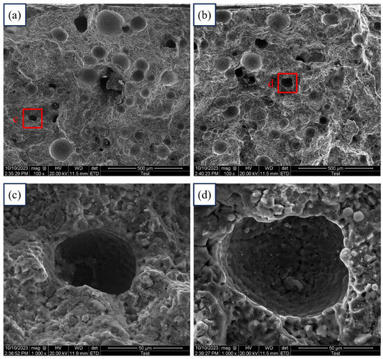
Figure 7.
Porosity distribution and morphology on the fracture surface: (a,b) distribution of pores; (c,d) morphological characteristics of pores.
As can be seen from Figure 7, the pore inside the laser-MIG hybrid-welded joint of the aluminum alloy is large in size and irregular in shape; the pores inside are full of folds and not smooth, and there are traces of liquid metal flow. Therefore, it was determined that the porosity is process porosity caused by the instability of keyholes formed by laser beam irradiation in the molten pool. The existence of pore defects will cause the hardness, tensile strength, and corrosion resistance of welded joints to decrease and will seriously affect the service performance of welded joints. The porosity defects formed during laser welding of aluminum alloys have always been an important research topic for domestic and foreign scholars [28,29].
As a high-energy, high-density, and highly penetrating heat source, the laser produces a typical keyhole effect during the welding process. Only a stable keyhole can provide an effective escape channel for bubbles. The pressure from the laser beam irradiation causes the molten pool of metal to arrange itself into a keyhole shape; the keyhole remains stable by balancing the force of gravity on the liquid metal with the force of its surface tension. For the keyhole to maintain a stable state, it must achieve force equilibrium. In laser-MIG hybrid welding, the addition of the MIG arc facilitates the disruption of stress equilibrium in the keyhole, leading to keyhole collapse and the formation of process porosity. Through the literature published by other researchers and our own preliminary tests, we found that the porosity of aluminum alloy laser-MIG composite welding is affected by the influence of welding parameters such as laser power, welding current, and defocusing amount. The main reason for the formation of stomata is the unstable state of keyholes. The change in defocus will affect the shape and stability of the keyhole in the weld pool and thus affect the porosity of the weld. No porosity defect can be found in the weld after welding if the defocusing amount is adjusted appropriately. Therefore, ensuring the stability of keyholes is the key to avoiding the formation of process porosity in aluminum alloy laser-MIG hybrid welding. In this study, the defocusing amount was varied while keeping the laser power, welding speed, welding current, and distance between laser and arc constant. Nine sets of laser-MIG hybrid welding tests were conducted on 7075 aluminum alloy butt plates with different defocusing amounts to investigate the impact of the defocusing amount on welding pores. The test process parameters for the influence of the defocusing amount on the porosity and keyhole morphology of welding seam are shown in Table 3. After welding, X-Ray flaw detection was carried out on the weld corresponding to each defocus quantity, and the distribution of porosity in the weld was observed. After the X-Ray film photography, the local threshold method was adopted to clearly observe the location of porosity distribution in the weld and accurately calculate the proportion of porosity in the weld. After the local threshold method, the film was white as a whole, and the pores were black. For different defocus quantities, the X-Ray films and their processing results are shown in Table 4.

Table 3.
The defocusing amount affects the tested technological parameters of porosity and keyhole morphology.

Table 4.
Porosity detection results in welds under different defocus conditions.
Table 4 illustrates that at a defocus of −3 mm, a high density of porosity can be observed in the weld, with both the number and size reaching their maximum. As the defocus shifts from −3 mm towards positive values, there is a noticeable decrease in both the quantity and dimensions of pores within the weld. Notably, at a defocus of +12 mm, no pores are detected in the weld. During testing, when the defocus value exceeds +12 or falls below −12, the quality of weld formation is compromised, resulting in the re-emergence of pores within the welded joint. This occurs because non-optimal defocus—whether too large or too small—leads to a reduction in laser energy density, causing the keyhole to lose its stable state without collapsing and consequently generating a limited number of pores. To accurately quantify porosity within the weld, this study utilizes software to measure pore area on the welded plate and subsequently calculates porosity under varying defocus conditions using Equation (1).
In Equation (1), where n represents porosity, SP denotes the area of a single pore, and SW stands for weld area. Due to the presence of both the weld and a portion of the base material in the X-Ray test negative image, the value of SW in this study is defined as half of the area covered by the X-Ray test negative.
The statistical observations on weld porosity under varying defocus conditions are depicted in Figure 8. At a defocus of −3 mm, the weld exhibits maximum porosity at 5.9%. Conversely, at a defocus of +12 mm, no discernible porosity is evident in the weld. As the defocus decreases from −3 mm to −6 mm and then increases to 0 mm, there is a notable reduction in weld porosity to 60% and 45%, respectively; however, it remains relatively high. Furthermore, across nine preset groups of different defocus tests, when the defocus is either −12 mm or +12 mm, resulting in scattered laser beam focus, the porosity in the weld measures less than 1%.
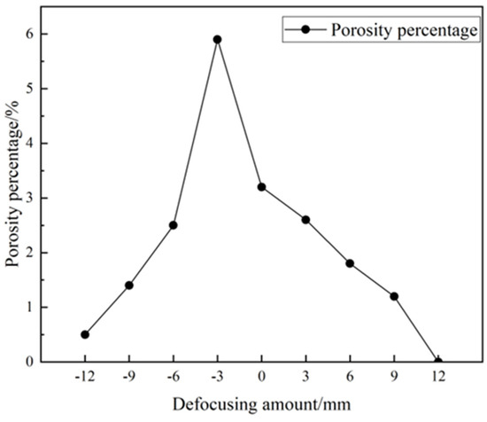
Figure 8.
Influence of defocusing amount on porosity.
3.2. Influence of Defocusing Amount on Keyhole Morphology
The dynamic changes in keyhole morphology in nine groups of “sandwich”-structured laser-MIG hybrid welds under varying defocusing amounts as listed in Table 3 were captured using high-speed camera equipment. The keyholes’ dynamic behavior was categorized into five types: no keyhole formation, collapse of the keyhole root, complete instability of the keyhole, instability of the keyhole root, and stability of the keyhole.
3.2.1. No Keyhole Formed
When the defocus is −3 mm, no discernible keyhole can be observed in the high-speed camera-captured image, as depicted in Figure 9. Among these images, those taken at t + 6 ms, t + 8 ms, and t + 10 ms exhibit slight keyhole formation; however, it is notably unstable. The keyhole collapses at t + 12 ms and does not provide sufficient support for bubble release within its brief duration of existence, leading to the detection of numerous pores in the butt joint.
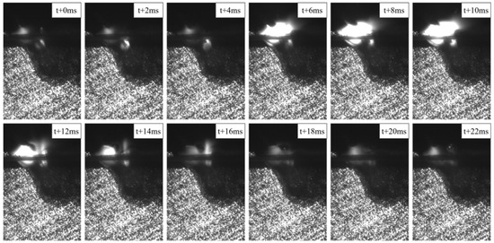
Figure 9.
No keyhole is formed when the defocusing amount is −3 mm.
3.2.2. Collapse of Keyhole Root
When the defocus is 0 mm, +3 mm, or −6 mm, the dynamic behavior changes of the keyholes captured by high-speed photography are similar. During the whole welding process, the root keyhole cannot take shape and is always in a collapsing state, while the upper keyhole is always in a stable open state; this situation is called collapse of the keyhole root, as shown in Figure 10. The morphology of the keyhole at a defocus of 0 mm is depicted in Figure 10a. The laser beam is precisely focused on the surface of the test plate, resulting in minimal width and depth of the keyhole. When the defocus is increased to +3 mm, the depth of the keyhole becomes significantly greater, as shown in Figure 10b. When the defocus is reduced to −6 mm, the width of the keyhole becomes significantly greater, as shown in Figure 10c. The collapse of the keyhole at its base can serve as an effective escape pathway for bubbles in the upper region of the molten pool while impeding the release of bubbles in the lower region, thereby accounting for the elevated porosity in welds made under these defocusing conditions.
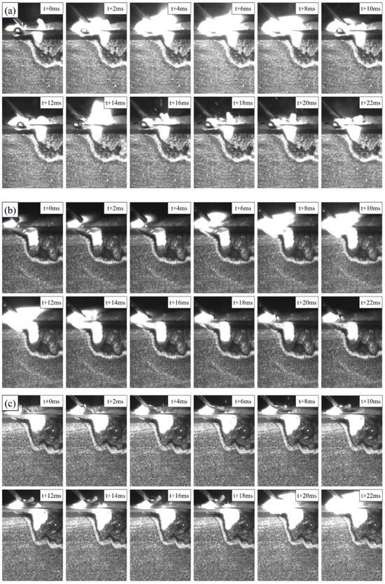
Figure 10.
Collapse of the keyhole root. (a) The defocus is 0 mm. (b) The defocus is +3 mm. (c) The defocus is −6 mm.
3.2.3. Complete Instability of the Keyhole
When the defocus increased to +6 mm or decreased to −9 mm, the keyhole shape inside the weld was completely unstable under high-speed photography, as shown in Figure 11. Complete instability of the keyhole means that the keyhole can hardly maintain a stable state during the welding process, and with the movement of the laser beam, the keyhole may completely collapse at any time. When the defocus is +6 mm, as depicted in Figure 11a, the keyhole begins to collapse at t + 4 ms due to sidewall folding, and by t + 10 ms, it has fully collapsed. The condensed metal vapor and protective gas rapidly cool, trapping weld bubbles within the channel and forming a small air mass at the base of the molten pool. The collapsed keyhole begins to be rebuilt until t + 22 ms, during which the small air mass at the bottom of the molten pool is driven by the force of the metal vapor towards the rear of the molten pool to form pores. As shown in Figure 11b, at a defocus of −9 mm, the keyhole collapse process exhibits complete instability; however, the resulting keyhole width and depth are greater, rendering the keyhole relatively more stable. The time of complete keyhole collapse is earlier, ranging from t + 12 ms to t + 16 ms. This observation suggests that the residence time of the keyhole before collapse decreases with an increase in the diameter of the spot illuminated by the laser beam on the test plate surface. Furthermore, it elucidates that the porosity in the weld is lower at a defocus of −9 mm than at −6 mm, as illustrated in Figure 8.
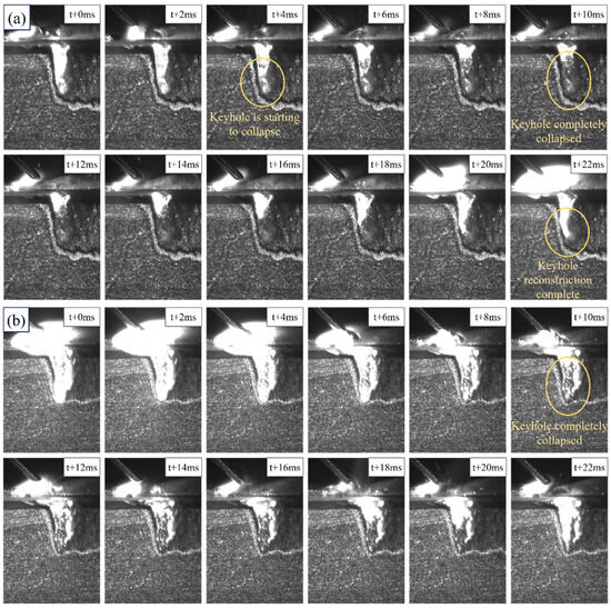
Figure 11.
Complete instability of the keyhole. (a) The defocus is +6 mm. (b) The defocus is −9 mm.
3.2.4. Instability of the Keyhole Root
With a further increase or decrease in defocus, when the defocus is +9 mm or −12 mm, the keyhole morphology is unstable at the root, as shown in Figure 12. In contrast to complete instability of the keyhole, the upper part of the keyhole with the root instability remains in a stable open state; only the lower part of the keyhole collapses with the movement of the laser beam. In contrast to collapse of the keyhole root, the lower part of the unstable keyhole is no longer closed, thus providing a channel for the escape of bubbles at the bottom of the molten pool. Keyholes with root instability neck in the middle, the volumes of trapped metal vapor and protective gas decrease, and the size of the air mass formed at the bottom of the molten pool decreases. With the reconstruction of the keyhole, the number and size of air masses formed by the violent rushing of metal vapor to the rear of the molten pool decreased. The number of pores formed in the weld due to the instability of the keyhole root is small, and the porosity is usually less than 1%.
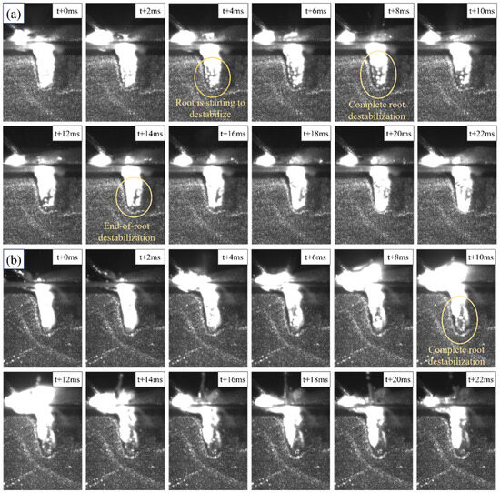
Figure 12.
Instability of the keyhole root. (a) The defocus is +9 mm. (b) The defocus is −12 mm.
3.2.5. Stability of the Keyhole
When the defocus is +12 mm, the keyhole is in a stable open state during the entire welding process, as shown in Figure 13. The stable keyhole can provide an escape channel for the bubbles, which is conducive to the escape of the bubbles behind the molten pool. Under this condition, the joint has a good macroscopic shape, and no porosity defects are detected in the weld.
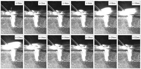
Figure 13.
Stability of the keyhole when the defocusing amount is +12 mm.
3.3. Mechanism Whereby the Defocusing Quantity Affects Keyhole Shape
Through the above tests, it is found that the change of the keyhole shape in the weld under different defocusing quantities has a direct effect on the porosity of the weld. During the process of laser-MIG hybrid welding of aluminum alloys, the formation of process porosity is a common occurrence. This can be attributed to the high energy, density, and penetration of the laser as a heat source, which creates stable keyholes in the molten pool. These keyholes play a crucial role in providing effective escape channels for bubbles, as illustrated in Figure 14. From a mechanical point of view, a keyhole comes from the pressure of the laser beam shining on the molten pool to push the molten pool metal to all four sides, but the liquid metal tends to close the keyhole under the action of its own weight, and in order for the keyhole to maintain a stable state, its forces must maintain balance. In laser-MIG hybrid welding, the addition of the MIG arc makes it easier to break the stress balance of the keyhole, and the root of the keyhole or the entire keyhole is unstable, leading to its collapse [30], preventing the escape of bubbles from the molten pool and thus forming pores in the weld.
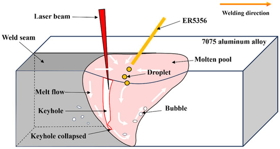
Figure 14.
Schematic diagram of the principle of “process porosity” formation.
The main factors affecting the shape of the keyhole are the metal vapor pressure on the inner wall of the keyhole and the pressure of the liquid metal on the outer wall of the keyhole under gravity [31]. To maintain the keyhole in a stable open state and provide an escape channel for bubbles during welding, the metal vapor pressure on the keyhole and the pressure applied by the liquid molten pool under gravity must be balanced [32]. These two forces are only related to the thermal action of the complex heat source, i.e., the laser and the MIG arc, on the molten pool. The thermal action of the keyhole in the molten pool is modeled and analyzed as follows.
The keyhole is placed in a three-dimensional coordinate system represented by (r, φ, z), where r represents the radial coordinate centered on the laser beam, φ represents the azimuth angle, and z represents the axial coordinate. Assuming that there is no heat loss before the laser beam illuminates the molten pool and that all the energy of the laser beam acts on the molten pool formed by the MIG arc, the temperature field distribution in the keyhole of the molten pool formed by laser-MIG hybrid welding can be expressed by Equation (2) [33].
In the equation, represents the metal melting point, denotes the thermal conductivity of the material, stands for laser power absorbed per unit depth, refers to the second class of zero-order Bessel functions, and signifies the Peclet number.
The Peclet number is a dimensionless parameter associated with welding speed and the thermal physical properties of materials; it can be expressed by Equation (3) [33].
In the equation, represents the thermal diffusion coefficient of the material.
Because the inner wall of the keyhole is subjected to the heat action of metal vapor and the outer wall is subjected to the heat action of liquid metal, the temperature of the keyhole wall should be between the metal’s melting point, , and the metal’s boiling, point . Assuming that the temperature of the keyhole wall is raised from the metal melting point to the metal boiling point, in Equation (2) can be expressed as follows:
When the laser beam irradiates to the surface of the molten pool, part of the heat is lost due to the reflection of the light, and part of the heat is lost due to the refraction of the light; only the remaining heat will be absorbed by the molten pool. This part of the heat absorbed by the molten pool can be described by the Fresnel absorption power [34,35], and the Fresnel absorption power () of the keyhole wall per unit depth can be expressed by Equation (5).
In Equation (5), represents the power density of the laser beam, and denotes the reflectivity of the liquid metal surface in the molten pool to the thermal energy of the laser beam. If the laser power absorbed by the molten pool per unit depth is equivalent to the Fresnel power absorbed by the keyhole wall per unit depth, Equations (4) and (5) can be combined to derive the following:
In Equation (6), the variable represents the radius of the keyhole at depth . When , the value of denotes the focusing radius of the laser beam. Conversely, when , the variable signifies the maximum depth of the keyhole. Since the base material used in this test is 7075 aluminum alloy and the welding material is ER5356 aluminum alloy, the parameters representing the thermal physical properties of the materials mentioned above should be constant. In this test, the laser power, welding speed, and laser incidence angle did not change, and the welding process parameters in the above tables should also be constant except for the defocusing amount. By combining all the constants into a single constant , Equation (6) can be simplified to the following:
According to Equation (7), if the above conditions remain unchanged, the shape of the keyhole is only related to the radius of the spot where the laser beam reaches the workpiece surface, and the parameter that affects the size of the spot where the laser beam illuminates the workpiece surface is the defocusing amount. The equation explains that the change in the defocusing amount is the fundamental reason for the changes in keyhole shape and porosity in a weld.
4. Conclusions
In this paper, the “sandwich” technique was employed, utilizing quartz glass for lateral observation of the formation position and movement characteristics of the keyhole in the molten pool. The dynamic behavior of the keyhole under nine different defocusing conditions was captured through high-resolution photography, and an analysis was conducted on how varying degrees of defocusing influence keyhole morphology. Furthermore, the porosity of welded joints under varying defocusing levels was quantified and computed to elucidate the intrinsic relationship between keyholes’ dynamic behavior and joint porosity. The following conclusions were drawn:
1. The keyhole is formed in the liquid molten pool formed by the laser beam, and the stability of the keyhole directly affects the porosity of the weld. A stable keyhole can provide a “channel” for bubbles to escape, which is conducive to the escape of bubbles from the molten pool. The side wall of an unstable keyhole is stressed unevenly; the root of the keyhole or even the whole keyhole is prone to collapse, and the liquid metal of the molten pool is backfilled, preventing the escape of bubbles from the bottom of the keyhole.
2. With an increase in the positive or negative defocusing amount, the dynamic behavior of the keyhole in the molten pool changes, and the porosity of the weld decreases. When the defocus is −3 mm, no keyhole is formed in the molten pool, and the porosity of the weld is the highest, at 5.9%. When the defocus is 0 mm, +3 mm, or −6 mm, the keyhole root collapses. When the defocus is +6 mm or −9 mm, the keyhole is completely unstable. When the defocus is +9 mm or −12 mm, the keyhole root is unstable. When the defocus is +12 mm, the keyhole is in a stable open state, and the porosity of the weld is 0%.
Author Contributions
Conceptualization, Y.X.; Investigation, Y.X., F.W. and Y.Z; Data curation, Y.X. and Y.Z.; Writing—original draft, Y.X.; Writing—review and editing, F.W., Y.Z., J.F., Z.S. and D.Z.; Supervision, F.W., Y.Z. and J.F.; Funding acquisition, F.W. All authors have read and agreed to the published version of the manuscript.
Funding
This research was funded by the Natural Science Foundation of Jiangsu Province Grant No. BK20241010.
Institutional Review Board Statement
Not applicable.
Informed Consent Statement
Not applicable.
Data Availability Statement
Data are contained within the article.
Acknowledgments
The authors gratefully acknowledge the financial support of the Natural Science Foundation of Jiangsu Province (Grant No. BK20241010).
Conflicts of Interest
The authors declare that they have no known competing financial interests or personal relationships that could have appeared to influence the work reported in this paper.
References
- Steen, W.M. Arc augmented laser processing of materials. J. Appl. Phys. 1980, 51, 5636–5641. [Google Scholar] [CrossRef]
- Duan, C.F.; Yang, S.L.; Gu, J.X.; Xiong, Q.; Wang, Y. Microstructure and ratcheting behavior of 6061 aluminum alloy laser-MIG hybrid welding joint. Mater. Res. Express 2019, 6, 086534. [Google Scholar] [CrossRef]
- Cai, C.; He, Y.; Xie, J.; Yu, J.; Xu, L.D.; Chen, Z.; Li, Z.X.; Wang, E.H.; Chen, H. Porosity suppression mechanism analysis in narrow-gap oscillating laser-MIG hybrid welding of aluminum alloys based on keyhole stability and molten pool flow behavior. J. Mater. Res. Technol. 2024, 32, 502–518. [Google Scholar] [CrossRef]
- Shibata, K.; Sakamoto, H.; Iwase, T. Laser-MIG hybrid welding of aluminum alloys. Weld World 2006, 50, 28–34. [Google Scholar] [CrossRef]
- Leo, P.; Renna, G.; Casalino, G.; Olabi, A.G. Effect of power distribution on the weld quality during hybrid laser welding of an Al–Mg alloy. Opt. Laser Technol. 2015, 73, 118–126. [Google Scholar] [CrossRef]
- Leo, P.; D’Ostuni, S.; Casalino, G. Hybrid welding of AA5754 annealed alloy: Role of post weld heat treatment on microstructure and mechanical properties. Mater Design 2016, 90, 777–786. [Google Scholar] [CrossRef]
- Sun, Z.; Salminen, A.S.; Moisio, T.J. Quality improvement of laser beam welds by plasma control. J. Mater. Sci. Lett. 1993, 12, 1131–1133. [Google Scholar] [CrossRef]
- Çam, G.; İpekoğlu, G. Recent developments in joining of aluminum alloys. Int. J. Adv. Manuf. Tech. 2017, 91, 1851–1866. [Google Scholar] [CrossRef]
- Jin, X.Z.; Zeng, L.C.; Cheng, Y.Y. Direct observation of keyhole plasma characteristics in deep penetration laser welding of aluminum alloy 6016. J. Phys. D Appl. Phys. 2012, 45, 245205. [Google Scholar] [CrossRef]
- Yan, J.; Gao, M.; Li, G.; Zhang, C.; Zeng, X.Y.; Jiang, M. Microstructure and mechanical properties of laser-MIG hybrid welding of 1420 Al-Li alloy. Int. J. Adv. Manuf. Tech. 2013, 66, 1467–1473. [Google Scholar] [CrossRef]
- Bai, P.C.; Dong, T.S.; Hou, X.H.; Zhao, C.W.; Xing, Y.M. Microstructure and mechanical properties of spray-deposited Mg–12.55 Al–3.33 Zn–0.58 Ca–1Nd alloy. Mater. Charact. 2010, 61, 756–760. [Google Scholar]
- Yan, S.H.; Xing, B.B.; Zhou, H.Y.; Xiao, Y.; Qin, Q.H.; Chen, H. Effect of filling materials on the microstructure and properties of hybrid laser welded Al-Mg-Si alloys joints. Mater. Charact. 2018, 144, 205–218. [Google Scholar] [CrossRef]
- Lin, R.Q.; Wang, H.P.; Lu, F.G.; Solomon, J.; Carlson, B.E. Numerical study of keyhole dynamics and keyhole-induced porosity formation in remote laser welding of Al alloys. Int. J. Heat Mass. Tran. 2017, 108, 244–256. [Google Scholar] [CrossRef]
- Tammas-Williams, S.; Withers, P.J.; Todd, I.; Prangnell, P.B. The influence of porosity on fatigue crack initiation in additively manufactured titanium components. Sci. Rep. 2017, 7, 7308. [Google Scholar]
- Huang, L.J.; Wu, D.S.; Hua, X.M.; Liu, S.C.; Jiang, Z.; Li, F.; Wang, H.; Shi, S.J. Effect of the welding direction on the microstructural characterization in fiber laser-GMAW hybrid welding of 5083 aluminum alloy. J. Manuf. Process. 2018, 31, 514–522. [Google Scholar] [CrossRef]
- Xu, G.X.; Zheng, Z.Q.; Cao, Q.N.; Hu, Q.X.; Li, L.; Guo, Q.H.; Du, B.S. Numerical and experimental investigation on weld formation during laser+ MIG hybrid fillet welding of aluminum alloy in horizontal position. Int. J. Adv. Manuf. Tech. 2019, 102, 2683–2694. [Google Scholar] [CrossRef]
- Xu, G.X.; Li, L.; Wang, H.X.; Li, P.F.; Guo, Q.H.; Hu, Q.X.; Du, B.S. Simulation and experimental studies of keyhole induced porosity in laser-MIG hybrid fillet welding of aluminum alloy in the horizontal position. Opt. Laser Technol. 2019, 119, 105667. [Google Scholar] [CrossRef]
- Li, Y.; Zhao, Y.Q.; Zhou, X.D.; Zhan, X.H. Effect of droplet transition on the dynamic behavior of the keyhole during 6061 aluminum alloy laser-MIG hybrid welding. Int. J. Adv. Manuf. Tech. 2022, 119, 897–909. [Google Scholar] [CrossRef]
- Huang, S.; Xu, L.D.; Lou, M.; Chen, H.; Zhang, K.; Li, Y.B. Keyhole-induced pore formation mechanism in laser-MIG hybrid welding of aluminum alloy based on experiment and multiphase numerical model. J. Mater. Process. Tech. 2023, 314, 117903. [Google Scholar] [CrossRef]
- Matsunawa, A.; Mizutani, M.; Katayama, S. Porosity formation mechanism and its prevention in laser welding. Weld. Int. 2003, 17, 431–437. [Google Scholar] [CrossRef]
- Matsunawa, A.; Kim, J.D.; Seto, N.; Mizutani, M.; Katayama, S. Dynamics of keyhole and molten pool in laser welding. J. Laser Appl. 1998, 10, 247–254. [Google Scholar] [CrossRef]
- Miyagi, M.; Kawahito, Y.; Kawakami, H.; Shoubu, T. Dynamics of solid-liquid interface and porosity formation determined through X-Ray phase-contrast in laser welding of pure Al. J. Mater. Process. Tech. 2017, 250, 9–15. [Google Scholar] [CrossRef]
- Zhang, Y.; Chen, G.Y.; Wei, H.Y.; Zhang, J. A novel “sandwich” method for observation of the keyhole in deep penetration laser welding. Opt. Lasers Eng. 2008, 46, 133–139. [Google Scholar] [CrossRef]
- Zhang, Y.; Li, S.C.; Chen, G.Y.; Zhang, H.R.; Zhang, M.J. Characteristics of zinc behavior during laser welding of zinc “sandwich” sample. Opt. Laser Technol. 2012, 44, 2340–2346. [Google Scholar] [CrossRef]
- Chen, G.Y.; Zhang, M.J.; Zhao, Z.; Zhang, Y.; Li, S.C. Measurements of laser-induced plasma temperature field in deep penetration laser welding. Opt. Laser Technol. 2013, 45, 551–557. [Google Scholar] [CrossRef]
- Jin, X.Z.; Cheng, Y.Y.; Zeng, L.C.; Zou, Y.F.; Zhang, H.G. Multiple Reflections and Fresnel Absorption of Gaussian Laser Beam in an Actual 3D Keyhole during Deep-Penetration Laser Welding. Int. J. Opt. 2012, 1, 361818. [Google Scholar] [CrossRef]
- GB/T228-2002; Metallic Materials-Tensile Testing at Ambient temperature. General Administration of Quality Supervision, Inspection and Quarantine of the People's Republic of China: Beijing, China, 2002.
- Huang, L.J.; Hua, X.M.; Wu, D.S.; Li, F. Numerical study of keyhole instability and porosity formation mechanism in laser welding of aluminum alloy and steel. J. Mater. Process. Tech. 2018, 252, 421–431. [Google Scholar] [CrossRef]
- Zhao, Y.Q.; Zhou, X.D.; Liu, T.; Kang, Y.; Zhan, X.H. Investigate on the porosity morphology and formation mechanism in laser-MIG hybrid welded joint for 5A06 aluminum alloy with Y-shaped groove. J. Manuf. Process. 2020, 57, 847–856. [Google Scholar] [CrossRef]
- Zhu, B.Q.; Zhao, Y.; Chen, F.G.; Fu, J.; Wang, F.Y.; Chen, G.Q.; Qin, Y.H. Mechanism of pore suppression in aluminum alloy laser-MIG hybrid welding based on alternating magnetic field. J. Laser Appl. 2024, 36, 022016. [Google Scholar] [CrossRef]
- Zhang, Z.H.; Dong, S.Y.; Wang, Y.J.; Xu, B.S.; Fang, J.X.; He, P. Study on microstructures and mechanical properties of super narrow gap joints of thick and high strength aluminum alloy plates welded by fiber laser. Int. J. Adv. Manuf. Tech. 2016, 82, 99–109. [Google Scholar] [CrossRef]
- Zhan, X.H.; Zhao, Y.Q.; Liu, Z.M.; Gao, Q.Y.; Bu, H.C. Microstructure and porosity characteristics of 5A06 aluminum alloy joints using laser-MIG hybrid welding. J. Manuf. Process. 2018, 35, 437–445. [Google Scholar]
- Feng, Y.; Gao, X.; Zhang, Y.; Peng, C.; Gui, X.; Sun, Y.; Xiao, X. Simulation and experiment for dynamics of laser welding keyhole and molten pool at different penetration status. Int. J. Adv. Manuf. Tech. 2021, 112, 2301–2312. [Google Scholar]
- Wang, L.; Liu, Y.; Yang, C.G.; Gao, M. Study of porosity suppression in oscillating laser-MIG hybrid welding of AA6082 aluminum alloy. J. Mater. Process. Tech. 2021, 292, 117053. [Google Scholar]
- Salminen, A.; Piili, H.; Purtonen, T. The characteristics of high power fibre laser welding. Proc. Inst. Mech. Eng. Part C J. Mech. 2010, 224, 1019–1029. [Google Scholar]
Disclaimer/Publisher’s Note: The statements, opinions and data contained in all publications are solely those of the individual author(s) and contributor(s) and not of MDPI and/or the editor(s). MDPI and/or the editor(s) disclaim responsibility for any injury to people or property resulting from any ideas, methods, instructions or products referred to in the content. |
© 2024 by the authors. Licensee MDPI, Basel, Switzerland. This article is an open access article distributed under the terms and conditions of the Creative Commons Attribution (CC BY) license (https://creativecommons.org/licenses/by/4.0/).


