Article

The Influence of Nano-Silicon Carbide on the Properties of Aluminum Alloy Under Salt Dry–Wet Alternations

1
School of Mechanical Engineering, Xinjiang Industry Technical College, Urumqi 830021, China
2
Khorgos Guosheng Auto Mach Technology Co., Ltd., Khorgos 835000, China
3
School of Civil Engineering and Geographic Environment, Ningbo University, Ningbo 315000, China
4
School of Civil Engineering, Harbin Institute of Technology, Harbin 150090, China
*
Authors to whom correspondence should be addressed.
Coatings 2024, 14(11), 1472; https://doi.org/10.3390/coatings14111472
Submission received: 22 October 2024 / Revised: 14 November 2024 / Accepted: 19 November 2024 / Published: 20 November 2024

Abstract

:
In this study, the influence of silicon carbide on an aluminum alloy’s yield tensile strength, ultimate tensile strength, compressive strength, tensile toughness and impact toughness were investigated. Meanwhile, the aluminum alloy specimens were exposed to the dry–wet alternations with a 3% NaCl solution or 3% Na2SO4 solution. Scanning electron microscope (SEM) photos and scanning electron microscopy energy spectra (SEM-EDS) were obtained. The results indicate that the silicon carbide with a mass ratio of 0%~8% of the total mass of the aluminum alloy can increase the yield tensile strength, the ultimate tensile strength, and the compressive strength by rates of 0%~30.4%, 0%~14.1% and 0%~13.1%. However, when the mass ratio of the silicon carbide increased from 8% to 10%, the yield tensile strength, the ultimate tensile strength and the compressive strength decreased by rates of 0%~3.2%, 0%~2.6% and 0%~0.43%. The tensile toughness and the impact toughness decreased when silicon carbide was added, with reduction rates of 0%~15.3% and 0%~12.8%. The NaCl dry–wet alternations led to decreases in the yield tensile strength, the ultimate tensile strength, the compressive strength, the tensile toughness and the impact toughness by rates of 0%~7.3%, 0%~6.7%, 0%~13.9%, 0%~12.7% and 0%~11.2%, respectively. After the Na2SO4 dry–wet alternations, the corresponding decreasing rates were 0%~5.1%, 0%~5.4%, 0%~1.73%, 0%~11.4% and 0%~9.7%. The addition of silicon carbide resulted in a decrease in the effect on the mechanical strength by the NaCl and Na2SO4 dry–wet alternations. The elements carbon, oxygen, magnesium, aluminum and silicon were observed in the aluminum alloy. The structures of the aluminum alloy with 8% silicon carbide were the highest.

1. Introduction

Aluminum alloy is a widely used metal material in the aerospace industry, electronic packaging, the automotive industry, the rail industry, the navigation industry, and the fields of transportation and building materials [1,2]. In anti-corrosion technology, aluminum alloy has been used as a coating material to protect metals from corrosion. Vu et al. have reported that aluminum–zinc alloy and calcium aluminum alloy coatings on steel can protect the steel from corrosion [3,4]. Unlike non-metallic materials, aluminum alloys show good heat resistance and compactness, a high specific strength, a high specific modulus, good thermal conductivity, high wear resistance, low thermal conductivity and an excellent coefficient of expansion [5,6]. Compared with steel and copper, aluminum alloys is more lightweight [7,8]. Additionally, when aluminum alloys are exposed to air, a dense oxide film will form on the surface of the aluminum alloy, which can protect the material from further corrosion [9,10]. However, when aluminum alloys are used in special environments, such as those exposed to marine erosion, their performance may deteriorate due to the corrosive effect of salts [11,12]. Therefore, it is necessary to add substances that can enhance the performance of aluminum alloys in order to improve their mechanical and durable properties.
Nano-silicon carbide is a nanoscale semiconductor filling material and has been used as a kind of effective filler for enhancing aluminum alloys [13,14]. Titanium carbide, titanium boride and aluminum oxide have been used to enhance the mechanical properties and the corrosion resistance of aluminum alloys [15,16,17]. Compared with these materials, nano-silicon carbide has a lower coefficient of thermal expansion which is beneficial for improving its durability. Moreover, nano-silicon carbide possesses higher hardness and wear resistance, and better mechanical performance and thermal stability. The incorporation of aluminum nano-silicon carbide particles has been shown to significantly enhance an aluminum alloy’s compressive and tensile strengths [18,19,20]. Wang et al. [21,22,23] have reported that nano-silicon carbide at a mass ratio of 9.3% can increase an aluminum alloy’s tensile strength to 213 MPa and the compressive strength to 425 MPa, increases of 31.6% and 24.2%. However, the aluminum alloy’s tensile toughness was decreased by the addition of nano-silicon carbide [24,25,26,27]. Although the influence of nano-silicon carbide on aluminum alloys’ mechanical properties has been investigated by several scholars, little attention has been paid to the mechanical strength of aluminum alloys with nano-silicon carbide that have been exposed to NaCl and Na2SO4 dry–wet alternations.
Due to being a kind of metal material, aluminum alloys can easily corrode due to the loss of electrons [28,29]. Aluminum alloys encounter the erosive effect of salts when exposed to marine engineering environments. The corrosive effect of salts can damage the passivation film on the surface of aluminum alloys, causing corrosion of the aluminum alloys [30,31]. Zhao et al. [32,33] found that SiC can improve aluminum alloys’ corrosion resistance by decreasing the corrosion current and electrochemical corrosion action. SiC has been reported to improve aluminum alloys’ service life [34,35]. However, the attenuation law of the mechanical properties of aluminum alloys in salt environments has rarely been studied by researchers. Dry–wet alternations of NaCl and Na2SO4 are common salt erosion conditions that are encountered by aluminum alloy materials in coastal environments [36,37,38]. Hence, in this study, dry–wet alternations of NaCl and Na2SO4 were selected as the typical erosive environments.
The influence of nano-silicon carbide on an aluminum alloy’s properties was investigated in this study. The mechanical performances, including the yield tensile strength, the ultimate tensile strength, the compressive strength, the tensile toughness and the impact toughness, were investigated in this study. The mass ratio of the nano-silicon carbide added to the aluminum alloy varied from 0% to 10%. The specimens were exposed to dry–wet alternations of a 3% NaCl solution or 3% Na2SO4 solution. Scanning electron microscopy energy spectra (SEM-EDS) were obtained to reveal the variation in the mechanical properties of the aluminum alloy with nano-silicon carbide. The innovation of this study is the development of a new metal material: a nano-silicon carbide aluminum alloy. Moreover, the system’s mechanical performances including the static and impact performances when exposed to a typical simulated marine environment were investigated. This research provides new materials for the application of aluminum alloys in salt environments.

2. Experimental

2.1. Raw Materials

The 6061 aluminum alloy was selected as the base material for this study. The composition is shown in Table 1. Commercially available green silicon carbide (content ≥ 97%) with an average particle diameter of 500 nm, a density of 3.21 g/cm3, a high melting point of 2545 °C, an elastic modulus of 420 GPa, a thermal conductivity of 41.0 W·m−1·K−1, and a linear expansion coefficient of 5.12 × 10⁻⁶ °C−1 was used as the reinforcing material. The material exhibited a Mohs hardness of 9.5, making it extremely resistant to scratching and abrasion.

2.2. Specimen Preparation

The mass fractions of the aluminum alloy are shown in Table 2.
The composite slurry was prepared as follows. The roasted oxidation process was used to pretreat the SiC particles. First, the SiC particles were put into a preheated quartz crucible. The temperature was raised to 600 °C, and the holding time was 2~3 h. Next, the temperature was raised to 1000 °C for 6 h with constant stirring to ensure that the SiC particles were fully oxidized. An electronic scale was used to weigh the proportions of the 6061 aluminum alloy and silicon carbide particles. The silicon carbide particles were put into the prepared corundum crucible at 300 °C for the second preheating step to enhance its activity. The prepared 6061 aluminum alloy was put into the graphite crucible, and, at the same time, the temperature was raised to 700 °C for melting. After the alloy was melted, the surface was decontaminated and the temperature was lowered to 650 °C. The stirring temperature was set at 640 °C. The stirring paddle was made of high-temperature- and corrosion-resistant 316 stainless steel with four blades. The graphite coating on the surface after preheating could reduce corrosion. The stirring commenced, with argon introduced for protection, starting with the addition of particles at 300 rpm, and subsequently increasing to 700 rpm for complete integration of the particles. When stirring out of the vortex, a small amount of secondary preheated particles was added through the V-shaped groove. The second addition was made when they were fully saturated. The mixing time was controlled to be above 15 min. After the mixing was finished, the stirring was started at 680 °C~720 °C.
When the temperature rose to 680 °C~720 °C, the composite slurry could be casted. The experimental double-roll casting mill developed by Yanshan University was used for cooling casting and rolling in this study. The cloth flow device designed by the laboratory was used to ensure the homogeneity of the composite slurry. The surface of the casting rolls was coated with a layer of fine graphite emulsion to prevent the melt from sticking to the rolls. The roll gap was set at 2 mm. When preparing SiC/Al composite strips with a plate thickness of 2 mm, the height of the molten pool was controlled at about 30 mm, and the roll speed ranged from 1.4 mm/min to 3.6 mm/min. Thermocouples were used to measure the temperature inside the composite slurry and to remove the oxidized slag on the surface. The preparation and measurement procedures are shown in Figure 1.

2.3. Measurement Methods

2.3.1. Quasi-Static Tensile Test

For the details of the quasi-static tensile test process, refer to the Chinese standard GB/T 228-2002 [39]. The prepared SiC/Al composite cast-rolled sheet and strip were cut by wire cutting to obtain I-beam tensile specimens which were used to determine the tensile strength. The shape and dimensions of the specimens are shown in Figure 2. The INSPEKT TABLE 100, electronic universal testing machine provided by Beijing Yizun Times Technology Co., Ltd., Beijing, China, was used for the tensile strength tests in this study, using a maximum test force of 100 kN, test speed of 0.01 mm/min~400 mm/min and resolution of less than 1 μm. A wire strain gauge was attached to the specimen at the axial position, and then the strain gauge was connected to the strain-measuring instrument and the tensile force value was applied to the specimen at a speed of 5 mm/min until the specimen fractured. The force and strain values were recorded synchronously in the tensile test process. The final displacement of the specimen was obtained by multiplying the length of the specimen by the strain value of the specimen. Then, the force–displacement curves of the SiC/Al composite cast strip were obtained.

2.3.2. Compressive Strength Test

The INSPEKT TABLE 100 electronic universal testing machine was used to measure the compressive strength in this study. A compressive force was applied to a Φ15 mm × 20 mm aluminum alloy cylinder at a speed of 2 mm/min until the specimen was damaged. The details of the compressive strength test process are described in the Chinese standard GB/T 7314-2017 [40]. The average of 6 specimens for each set of compressive strength experiments was used as the final result.

2.3.3. Pendulum Impact Test

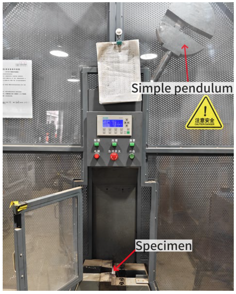
The pendulum impact test was performed in accordance with the GB/T 229-2020 standard [41]. The equipment used in this study was a ZBC-2302-2 impact tester with a maximum impact energy of 300 J. The specimen was placed on the test bench and clamped using a fixture. Before the beginning of the experiment, the starting position of the pendulum, the impact angle and the starting impact energy were adjusted. Then, the pendulum was released to impact the specimen. At the same time, the toughness of the material was quickly assessed by reading the data from the instrument. Figure 3 shows the equipment used for the pendulum impact test.

2.3.4. Tensile Toughness Test

The tensile toughness test was conducted using a 1.6 mm thickness pre-cracked aluminum alloy sample according to the American standard ASTM E399, i.e., “Standard Test Method for Linear-Elastic Plane-Strain Fracture Toughness of Metallic Materials” [42]. A WAW-1000B servo-hydraulic testing machine was used to test the tensile toughness. The specimen was placed on the tensile fixture and connected to the double cantilever displacement gauge. A load was applied at a speed of 2 mm/min until the specimen fractured. The force–displacement curves were derived synchronously using the tensile transducer and the displacement gauge. The tensile toughness was obtained from the integral of the tensile force vs. displacement. The lower limit of the integral was at the beginning of loading, and the upper limit was at the point of maximum stress.

2.3.5. Dry–Wet Alternations of NaCl and Na2SO4

The aluminum alloy specimens were immersed in 3% NaCl or 3% Na2SO4 solutions for 4 d before performing the dry–wet alternation experiment. The three steps were carried out as follows. The specimens were dried in an HZ-2014C electric blast drying oven (manufactured by Dongguan Lixian Instrument Technology Co., Ltd., Dongguan, China) at 80 °C for 12 h. Then, they were cooled to 20 °C for 2 h, and then fully immersed in a 3% NaCl or 3% Na2SO4 solution for 10 h at ambient temperature. When the immersion in the NaCl or Na2SO4 solution was finished, the water on the surface of the specimens was wiped with a damp cloth. The duration of each dry–wet alternation cycle was 24 h.

2.3.6. The Mass Loss Rate

The mass loss rate of the aluminum alloy was measured using the following steps. First, the mass of the aluminum alloy was measured using an electronic balance with a mass range of 3000 g and measurement accuracy of 0.01 g. The aluminum alloy’s mass was measured after immersion in the 3% NaCl or 3% Na2SO4 for two days. After 10 NaCl or 10 Na2SO4 dry–wet alternations, the rust on the surface was sanded clean with sandpaper. Then, the mass of the specimens was determined after each 10 NaCl or 10 Na2SO4 dry–wet alternation. The aluminum alloy’s mass loss rate (MLR) was calculated using Equation (1).
M L R = m m 0 m 0
where m0 and m are the mass before the dry–wet alternation and the mass after being exposed to 10 NaCl or 10 Na2SO4 dry–wet alternations. In this study, six specimens were selected for each test to ensure reproducibility.

2.3.7. Experiments to Measure Microscopic Properties

For the scanning electron microscopy and energy dispersive spectroscopy (SEM-EDS) experiments, a sample of a flat, rice-sized area was taken. A Nova Nano SEM with a resolution of 3.5 nm, an acceleration voltage of 500 V to 30,000 V, a magnification of 18 to 30,000 and a sample stage diameter of 30 mm, and a Brooke Quantum EDS spectrometer for micro-analysis were used to observe the microstructure and determine the elemental composition.

3. Results and Discussions

3.1. Mechanical Strengths

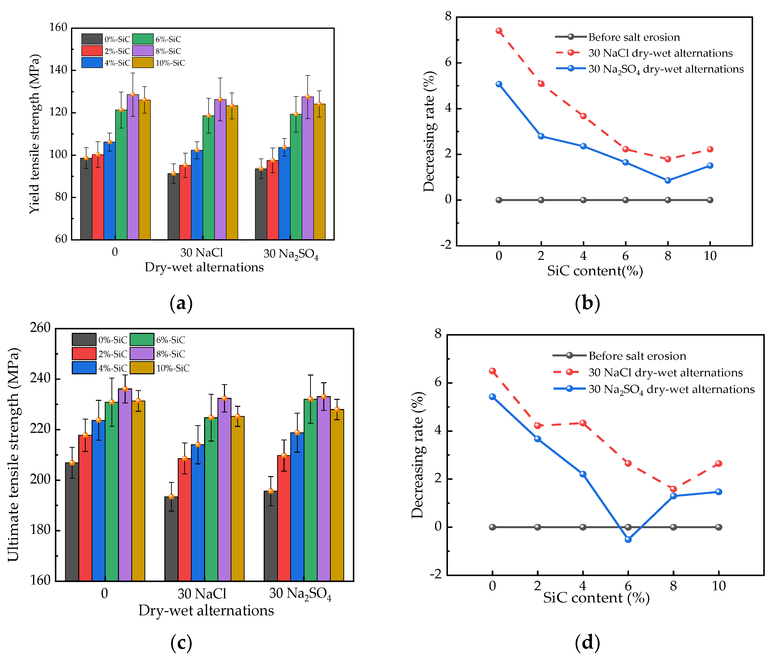
The yield tensile strength and the ultimate tensile strength results of the aluminum alloy are shown in Figure 4. As illustrated in Figure 4, the addition of silicon carbide produced a positive effect on the aluminum alloy’s yield tensile strength and ultimate tensile strength when the mass ratio of the silicon carbide was 0% to 8%. At this stage, the yield tensile strength and the ultimate tensile strength increased by rates of 0%~30.4% and 0%~14.1%, respectively. This was attributed to the fact that SiC, as an atomic crystal, has a higher strength than aluminum, thus improving the mechanical strength [43,44]. Moreover, SiC in an aluminum alloy can restrict the cracking of the aluminum alloy under stress, resulting in an increase in its mechanical strength [45,46]. Therefore, the addition of SiC at a mass ratio of 0%~8% increased the aluminum alloy’s tensile strength. However, when the SiC dosage was higher than 8%, the agglomeration of the SiC in the aluminum alloy led to a decrease in the strength of the aluminum alloy. Particle aggregation sites are prone to defects such as pores and looseness. Additionally, the particle aggregation area is highly susceptible to losing the load and the ability to withstand external loads [47,48]. Consequently, when the mass ratio of silicon carbide was 10%, the silicon carbide showed a negative effect on the yield tensile strength and the ultimate tensile strength. Moreover, as shown in Figure 4, the yield tensile strength and the ultimate tensile strength decreased by rates of 3.2% and 2.6%, respectively, compared with the yield tensile strength and the ultimate tensile strength of the aluminum alloy with 5% silicon carbide. Compared with the yield tensile strength and the ultimate tensile strength of the aluminum alloys with TiB2, Al2O3 and TiC, the yield tensile strength and ultimate tensile strength of the aluminum alloy with SiC were 11.3%~16.7% and 14.1%~16.2% higher [47,49]. Additionally, 30 NaCl dry–wet alternations reduced the yield tensile strength and the ultimate tensile strength by rates of 0%~7.3% and 0%~6.7%, respectively. Meanwhile, 30 Na2SO4 dry–wet alternations reduced the yield tensile strength and the ultimate tensile strength by rates of 0%~5.1% and 0%~5.4%, respectively. This can be explained by the fact that NaCl and Na2SO4 dry–wet alternations cause frequent contact between O2 and the aluminum metal. Meanwhile, the ionization speed and degree of electron loss in metals are accelerated [50]. Consequently, the NaCl and Na2SO4 dry–wet alternations corroded the aluminum metal, leading to a decrease in the tensile strength of the aluminum alloy. The increasing dosages of silicon carbide in the aluminum alloy decreased the reduction in yield tensile strength and the ultimate tensile strength by 30 NaCl dry–wet alternations and 30 Na2SO4 dry–wet alternations by 0%~2.8% and 0%~3.6%.
The compressive strength of the aluminum alloy is shown in Figure 5. As exhibited in Figure 5, the silicon carbide at a mass ratio of 2%~8% increased the aluminum alloy’s compressive strength by rates of 0%~13.1% due to the fact that silicon carbide has a higher mechanical strength than aluminum. Silicon carbide is also able to limit the cracking of aluminum alloys during loading [51,52]. Therefore, the aluminum alloy’s compressive strength increased with 2%~8% silicon carbide. When the mass ratio of silicon carbide increased from 8% to 10%, the aluminum alloy’s compressive strength decreased by a rate of 0%~0.43%. This can be explained by the weakness caused by the aggregation of silicon carbide, forming defects in the aluminum alloy [53,54]. Therefore, the mechanical strength and the corrosion of the aluminum alloy with silicon carbide at a mass ratio higher than 8% decreased. NaCl dry–wet alternations and Na2SO4 dry–wet alternations can decrease the compressive strength of aluminum alloys. The aluminum alloy’s compressive strength decreased by rates of 0%~2.01% and 0%~1.73% after 30 NaCl dry–wet alternations and Na2SO4 dry–wet alternations, respectively. This can be ascribed to the blocking effect of silicon carbide on electron ionization [55,56]. Therefore, the addition of silicon carbide can decrease the loss of compressive strength of aluminum alloys caused by NaCl and Na2SO4 dry–wet alternations. Compared with the compressive strength of aluminum alloys with TiB2, Al2O3 and TiC, the compressive strength of the aluminum alloy with SiC was 21.3%~36.1% higher [57].
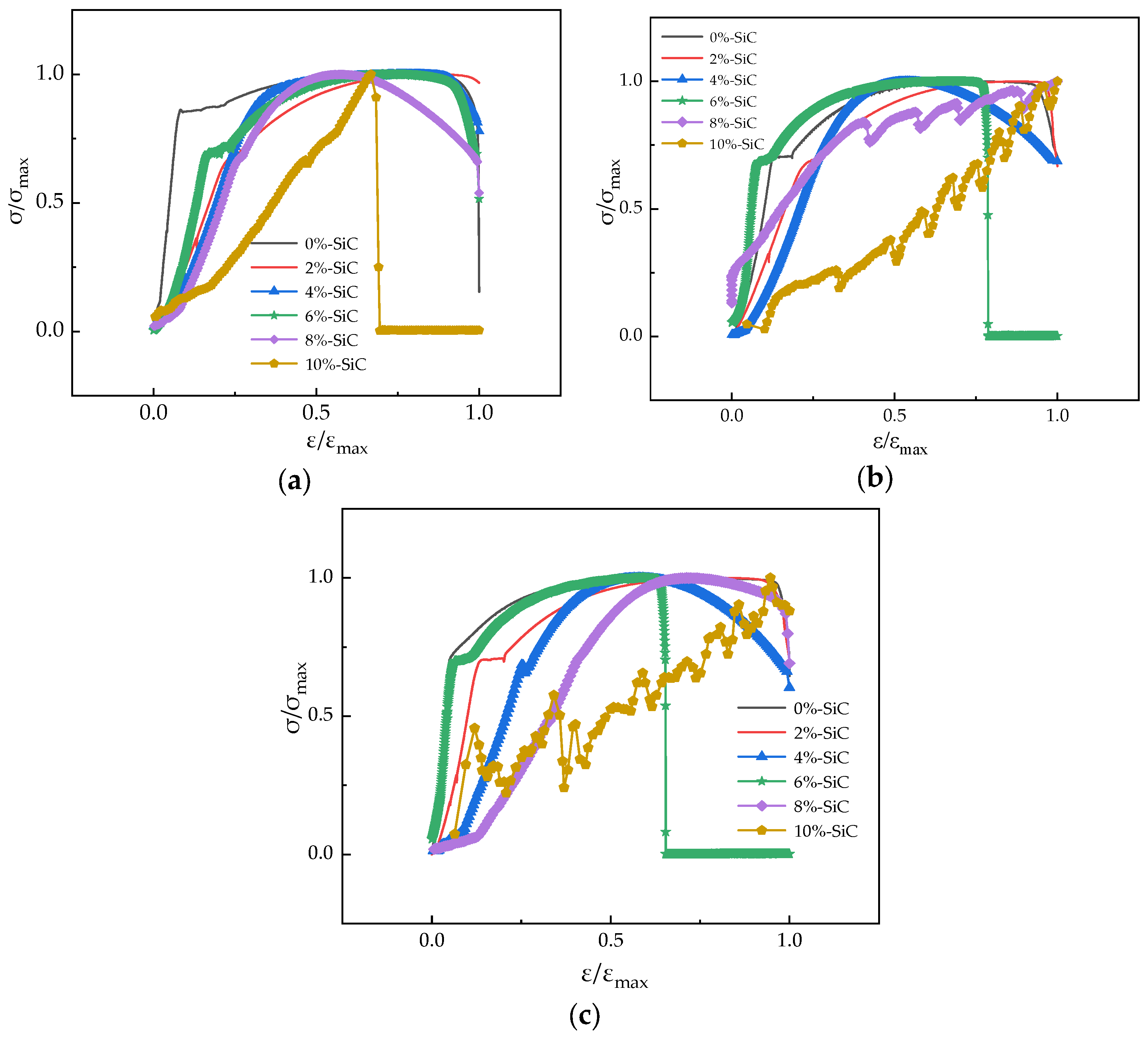
The stress ratio and strain ratio displacement curves are shown in Figure 6. As can be observed in Figure 6, the stress ratio increased linearly with the increase in strain ratio due to the aluminum alloy’s plasticity [58]. Meanwhile, when the tensile strain ratio continued to increase, the curves increased non-linearly with the increasing tensile stress. Finally, the tensile stress ratio decreased with increasing displacement when the ratio reached 100%. The addition of silicon carbide increased the tensile stress ratio’s increasing rate with the increase in displacement. This is ascribed to the fact that the silicon carbide particles can prevent the movement of dislocations, causing pinning effects, and thus improving the deformation ability and toughness [6]. Meanwhile, the NaCl and Na2SO4 dry–wet alternations led to increases in the rate of increase of the tensile stress ratio with the displacement. This can be explained by the fact that NaCl and Na2SO4 dry–wet alternations can promote the electrochemical reaction of aluminum alloys, resulting in the formation of loose substances [59]. Therefore, the aluminum alloy’s resilience decreased, while the corresponding brittleness increased.

3.2. Toughness

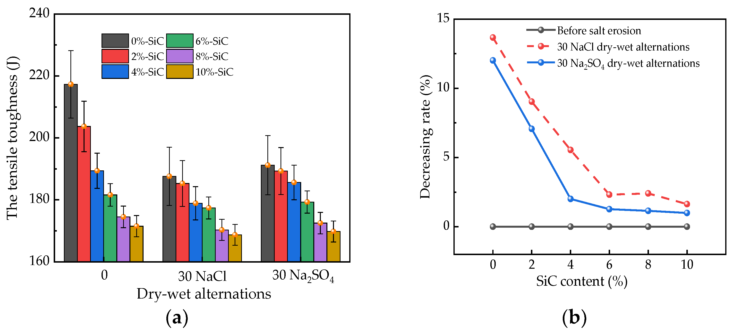
The tensile toughness of the aluminum alloy is shown in Figure 7. As illustrated in Figure 7, the tensile toughness decreased by rates of 0%~21.1% when the silicon carbide mass ratio increased from 0% to 10%. This can be ascribed to the fact that the mismatch in thermal expansion coefficients between the silicon carbide particles and aluminum alloy matrix results in a low interfacial bonding strength. When an external force is applied to the composite material, the harder silicon carbide particles become the sites of stress concentration, causing cracks to form and propagate around the particles, thereby reducing the material’s tensile toughness [60]. Additionally, the NaCl and Na2SO4 dry–wet alternations reduced the aluminum alloy’s tensile toughness. After the 30 NaCl dry–wet alternations and 30 Na2SO4 dry–wet alternations, the tensile toughness of the aluminum alloy decreased by rates of 0%~13.9% and 0%~11.8%. This can be explained by the fact that the thermal expansion coefficient of silicon carbide particles cannot match that of the aluminum alloy matrix, resulting in a low interfacial bonding strength. When an external force is applied to the composite material, the stress concentrates in the harder silicon carbide particles, causing cracks to form and propagate around the particles [61]. Consequently, the tensile toughness of the material decreases. Meanwhile, the addition of silicon carbide decreased the reduction in the aluminum alloy’s tensile toughness by 0%~12.7% and 0%~11.4% after 30 NaCl dry–wet alternations and 30 Na2SO4 dry–wet alternations. This can be attributed to the fact that the addition of silicon carbide can enhance the interfacial bonding strength. Moreover, the addition of silicon carbide hinders the migration of electrons in aluminum alloys, leading to an improvement in corrosion resistance [62]. Therefore, the addition of silicon carbide can decrease the reduction in the aluminum alloy’s tensile toughness.
Figure 8 shows the impact toughness of the aluminum alloy. As can be observed from Figure 8, the impact toughness of the aluminum alloy decreased by rates of 0%~26.6% when the mass ratio of silicon carbide increased from 0% to 10%. This can be explained by the fact that the thermal expansion coefficient of silicon carbide particles does not match that of the aluminum alloy matrix, resulting in a low interfacial bonding strength. When an external force is applied to the composite material, the harder silicon carbide particles become the site of stress concentration, causing cracks to form and propagate around the particles, thereby reducing the tensile toughness of the material [63]. The NaCl dry–wet alternations and Na2SO4 dry–wet alternations had a reducing effect on the aluminum alloy’s impact toughness, with decreasing rates of 0%~15.3% and 0%~12.8%, respectively. The addition of SiC particles can enhance the interfacial bonding between SiC and the aluminum alloy, slowing down the tensile toughness degradation caused by the NaCl and Na2SO4 dry–wet alternations [64]. Adding silicon carbide reduced the decrease in the aluminum alloy’s impact toughness by the NaCl dry–wet alternations and Na2SO4 dry–wet alternations by 0%~11.2% and 0%~9.7%, respectively. The decreasing rate of the impact toughness was higher after the 30 NaCl dry–wet alternations than after the 30 Na2SO4 dry–wet alternations. Compared with the tensile toughness and the impact toughness of the aluminum alloys with TiB2, Al2O3 and TiC, the tensile toughness and the impact toughness of the aluminum alloy with SiC were 17.1%~21.8% and 15.3%~18.9% higher [65].

3.3. Mass Loss Rates

The mass loss rates of the aluminum alloy with different dosages of silicon carbide are shown in Figure 9. As depicted in Figure 9, the mass loss rates increased with the number of NaCl and Na2SO4 dry–wet alternations. When the number of NaCl and Na2SO4 dry–wet alternations increased from 0 to 30, the mass loss rates increased from 0% to 1.32% and 1.26%, respectively. This can be explained by the fact that the corrosion of aluminum by sodium sulfate and sodium chloride is an electrochemical corrosion process that involves redox reactions between the aluminum and water. After the NaCl or Na2SO4 dry–wet alternations, aluminum oxide formed on the aluminum alloy. Therefore, the mass was decreased by the dry–wet alternations with the NaCl and Na2SO4 solutions [66]. Hence, the aluminum alloy’s mass decreased with the number of NaCl and Na2SO4 dry–wet alternations. Adding silicon carbide decreased the mass loss caused by the 30 NaCl or 30 Na2SO4 dry–wet alternations by rates of 0%~37.1% and 0%~37.3%, respectively. Silicon carbide can block the migration of electrons during NaCl and Na2SO4 dry–wet alternations. Therefore, the silicon carbide led to a decrease in the mass loss rates of the aluminum alloy. When the mass ratio of silicon carbide was 8%, the mass loss rate was the lowest.

3.4. Scanning Electron Microscope Photos

Figure 10 shows the scanning electron microscope (SEM) photos of the aluminum alloy with silicon carbide at mass ratios of 2%, 8% and 10%. Figure 10 illustrates the SiC particles, cracks and compact parts. When the added dosages of SiC increased from 2% to 8%, the number of cracks in the specimens decreased. However, when the mass ratio of SiC increased from 8% to 10%, the SiC increased the number of cracks in the specimens.
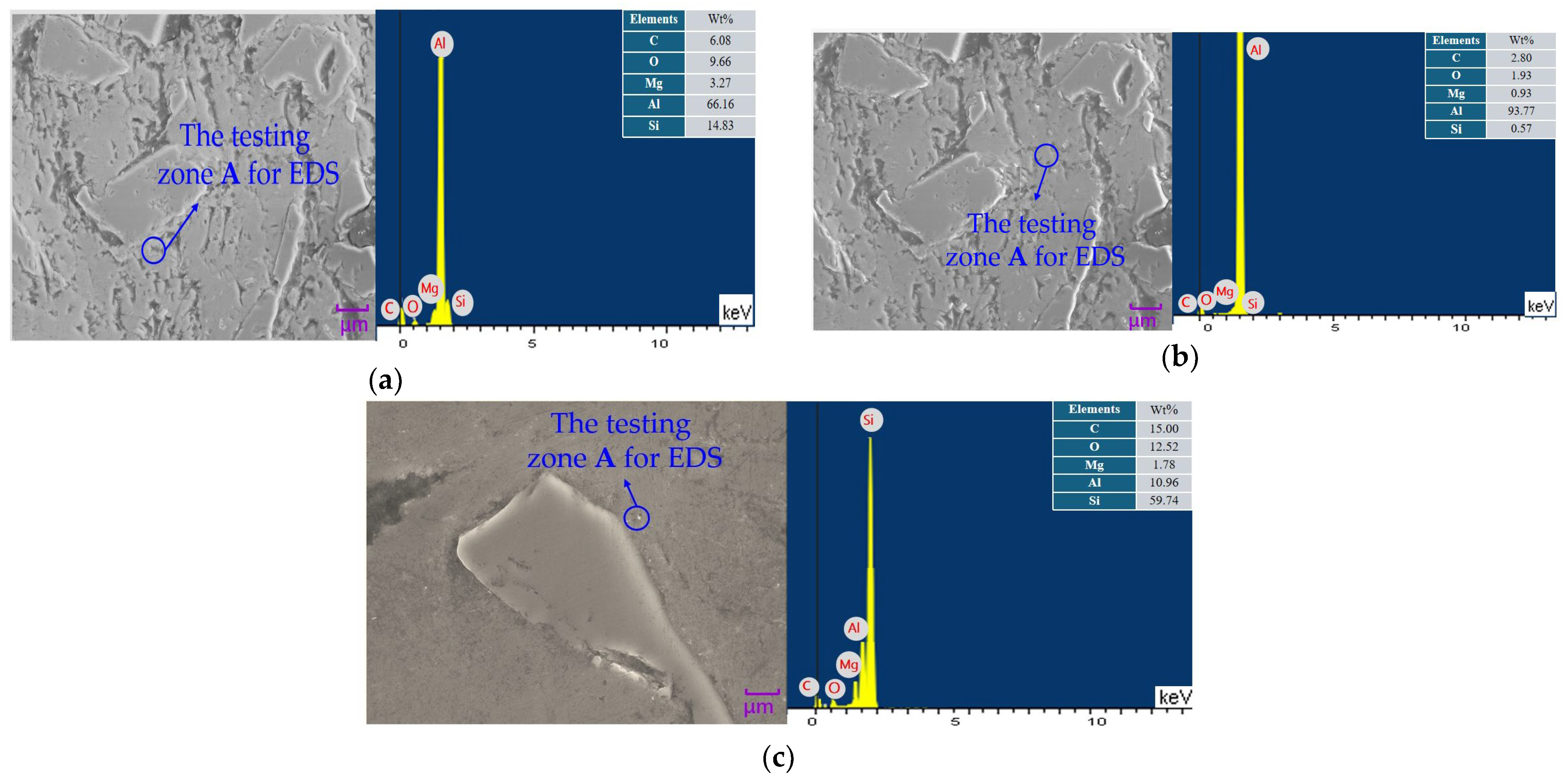
The SEM-EDS photos of the aluminum alloy with silicon carbide at mass ratios of 2%, 8% and 10% are shown in Figure 11. As shown in Figure 11, the elements C, O, Mg, Al and Si were found. The amounts of the elements Si and C were increased by adding silicon carbide. The elements C and Si were provided by the added nano-silicon carbide powder while O may have come from the oxide generated by the reaction of aluminum alloy with oxygen in the air. The element Mg may be a trace element in the aluminum alloy.

4. Conclusions

In this study, the influence of silicon carbide on an aluminum alloy’s mechanical properties was studied. The specimens were exposed to the NaCl and Na2SO4 dry–wet alternations. The conclusions can be summarized as follows.
The yield tensile strength, the ultimate tensile strength and the compressive strength increased by rates of 0%~30.4%, 0%~14.1% and 0%~13.1% when 0%~8% silicon carbide (by mass) of the aluminum alloy’s total mass was added. The added silicon carbide at rates of 8%~10% decreased the mechanical strengths by rates of 0%~3.2%, 0%~2.6% and 0%~0.43%. However, the silicon carbide decreased the tensile toughness and the impact toughness by rates of 0%~15.3% and 0%~12.8%, respectively.
The yield tensile strength, the ultimate tensile strength, the compressive strength, the tensile toughness and the impact toughness decreased by rates of 0%~7.3%, 0%~6.7%, 0%~13.9%, 0%~12.7% and 0%~11.2% after 30 NaCl dry–wet alternations, while after 30 Na2SO4 dry–wet alternations, the corresponding decreasing rates were 0%~5.1%, 0%~5.4%, 0%~1.73%, 0%~11.4% and 0%~9.7%. The addition of silicon carbide decreased the reduction in mechanical strength by the NaCl and Na2SO4 dry–wet alternations.
The mass loss rates of the aluminum alloy decreased by 0% to 1.32% and 0% to 1.26% after 30 NaCl dry–wet alternations and 30 Na2SO4 dry–wet alternations. The aluminum alloy with 8% silicon carbide showed the highest compactness.

Author Contributions

Methodology and origin writing, S.S.; Software, C.L.; Validation, W.C.; Formal analysis and revision, Z.W. and H.W.; Investigation, C.W. and F.S.; Data curation, Z.C. All authors have read and agreed to the published version of the manuscript.

Funding

Ningbo Natural Science Foundation 2023J086.

Institutional Review Board Statement

Not applicable.

Informed Consent Statement

Not applicable.

Data Availability Statement

Data are contained within the article.

Conflicts of Interest

Author Chuanyuan Liu was employed by the company Khorgos Guosheng Auto Mach Technology Co., Ltd. The remaining authors declare that the research was conducted in the absence of any commercial or financial relationships that could be construed as a potential conflict of interest.

References

  1. Chen, D.; Li, J.; Sun, K.; Fan, J. Graphene-Reinforced Metal Matrix Composites: Fabrication, Properties, and Challenges. Int. J. Adv. Manuf. Technol. 2023, 125, 2925–2965. [Google Scholar] [CrossRef]
  2. Lei, X.-F.; Ding, W.-F.; Zhao, B.; Qian, C.; Liu, Z.-A.; Liu, Q.; Xu, D.-D.; Zhao, Y.-J.; Zhu, J.-H. Grinding of Particle-Reinforced Metal Matrix Composite Materials: Current Status and Prospects. Adv. Manuf. 2024, 1–26. [Google Scholar] [CrossRef]
  3. Vu, A.Q.; Vuillemin, B.; Oltra, R.; Allély, C. Cut-edge corrosion of a Zn− 55Al-coated steel: A comparison between sulphate and chloride solutions. Corros. Sci. 2011, 53, 3016–3025. [Google Scholar] [CrossRef]
  4. Grandhi, S.; Oh, M.S. Investigated the effect of the Ca content on the microstructures and electrochemical properties of hot-dip aluminizing coatings on commercial quality steel. Mater. Lett. 2023, 353, 135278. [Google Scholar] [CrossRef]
  5. Rativa-Parada, W.; Nilufar, S. Nanocarbon-Infused Metal Matrix Composites: A Review. JOM 2023, 75, 4009–4023. [Google Scholar] [CrossRef]
  6. Taylor, A.; Klimša, L.; Kopeček, J.; Remeš, Z.; Vronka, M.; Čtvrtlík, R.; Tomáštík, J.; Mortet, V. Synthesis and Properties of Diamond - Silicon Carbide Composite Layers. J. Alloys Compd. 2019, 800, 327–333. [Google Scholar] [CrossRef]
  7. Ren, Q.; Yue, Z.; Soyarslan, C.; Tan, Z.; Yuan, F.; Li, Z. A Coupled Ductile Damage Model for Metal Matrix Composites: Development and Application. Compos. Part B Eng. 2024, 272, 111229. [Google Scholar] [CrossRef]
  8. Maity, J. An Analytical Model to Ascertain A.C. Electrical Conductivity of Metal Matrix Composites. Philos. Mag. 2024, 104, 1052–1075. [Google Scholar] [CrossRef]
  9. Yan, A.; Zhang, H.; Deng, B.; Peng, F.; Yan, R.; Cui, F. Analytical Modeling of Subsurface Damage in Laser-Assisted Machining of Metal Matrix Composites Based on the Reinforcement Fracture Probability. J. Manuf. Process. 2023, 109, 300–312. [Google Scholar] [CrossRef]
  10. Tajdary, P.; Dorhmi, K.; Morin, L.; Derrien, K.; Hadjem-Hamouche, Z.; Braham, C.; Chevalier, J.-P. Characterization and Modeling of the Damage Mechanisms in Ductile Steel Metal-Matrix Composites: Application to Virtual Forming. Mech. Mater. 2023, 184, 104741. [Google Scholar] [CrossRef]
  11. Kosaba, T.; Muto, I.; Sugawara, Y. Effect of anodizing on galvanic corrosion resistance of Al coupled to Fe or type 430 stainless steel in diluted synthetic seawater. Corros. Sci. 2021, 179, 109145. [Google Scholar] [CrossRef]
  12. Bai, L.-J.; Kou, G.; Zhao, K.; Chen, G.-T.; Yan, F.-X. Effect of in-situ micro-arc oxidation coating on the galvanic corrosion of AZ31Mg coupled to aluminum alloys. J. Alloys Compd. 2019, 775, 1077–1085. [Google Scholar] [CrossRef]
  13. Bagheri, M.; Alizadeh, M.; Ahmadi, A.; Hajizamani, M. A Quantitative Hot Tearing Criterion for Aluminum Alloys. Eng. Res. Express 2024, 6, 035545. [Google Scholar] [CrossRef]
  14. Wang, L.; Huang, X.; Li, R.; Tang, Z.; Li, J.; Chen, D. Collision Study on New Aluminum Alloy W-Beam Guardrail. Appl. Sci. 2024, 14, 5266. [Google Scholar] [CrossRef]
  15. Han, F.; Li, C.; Wang, Y.; Pai, Z.; Meng, Y.; Cao, M.; Liu, Y.; He, P.; Ma, X.; Xue, L.; et al. Comparative Study on Corrosion Property of 2219 Aluminum Alloy Sheet and Additively Manufactured 2319 Aluminum Alloy. J. Mater. Res. Technol. 2024, 30, 3178–3185. [Google Scholar] [CrossRef]
  16. Jayasathyakawin, S.; Ravichandran, M. Experimental Investigations on Effect of Silicon Carbide on Microstructure and Mechanical Properties in Mg-3 Wt% Al Alloy Matrix Using Powder Metallurgy. Silicon 2022, 14, 9163–9173. [Google Scholar] [CrossRef]
  17. Tang, M.; Liu, Y.; Liu, L.; Lin, T.; Liu, X. Microstructure and Mechanical Properties of SiC/SiC Joints Reinforced by in-Situ Growth SiC Nanowires. Mater. Charact. 2021, 179, 111315. [Google Scholar] [CrossRef]
  18. Özdemir, İ.; Cöcen, Ü.; Önel, K. The Effect of Forging on the Properties of Particulate-SiC-Reinforced Aluminium-Alloy Composites. Compos. Sci. Technol. 2000, 60, 411–419. [Google Scholar] [CrossRef]
  19. Sornakumar, T.; Kathiresan, M. Machining Studies of Die Cast Aluminum Alloy-Silicon Carbide Composites. Int. J. Miner. Metall. Mater. 2010, 17, 648–653. [Google Scholar] [CrossRef]
  20. Zuo, L.; Zhao, X.; Li, Z.; Zuo, D.; Wang, H. A Review of Friction Stir Joining of SiCp/Al Composites. Chin. J. Aeronaut. 2020, 33, 792–804. [Google Scholar] [CrossRef]
  21. Wang, W.; Li, Q.; Du, A.; Zhao, X.; Fan, Y.; Ma, R.; Cao, X. Excellent Thermal Shock Resistance of Al Alloy-Infiltrated SiC Composites. J. Mater. Process. Technol. 2019, 269, 16–25. [Google Scholar] [CrossRef]
  22. Huang, S.; Yu, X. A Study of Grinding Forces of SiCp/Al Composites. Int. J. Adv. Manuf. Technol. 2017, 94, 3633–3639. [Google Scholar] [CrossRef]
  23. Seah, K.H.W.; Sharma, S.C.; Rao, P.R.; Girish, B.M. Mechanical Properties of As-Cast and Heat-Treated ZA-27/Silicon Carbide Particulate Composites. Mater. Des. 1995, 16, 277–281. [Google Scholar] [CrossRef]
  24. Winiczenko, R.; Skibicki, A.; Skoczylas, P. The Experimental and FEM Studies of Friction Welding Process of Tungsten Heavy Alloy with Aluminium Alloy. Appl. Sci. 2024, 14, 2038. [Google Scholar] [CrossRef]
  25. Fan, J.; Xu, S. Aluminum Oxide Particles/Silicon Carbide Whiskers’ Synergistic Effect on Thermal Conductivity of High-Density Polyethylene Composites. Iran. Polym. J. 2018, 27, 339–347. [Google Scholar] [CrossRef]
  26. Shen, D.; Zhan, Z.; Liu, Z.; Cao, Y.; Zhou, L.; Liu, Y.; Dai, W.; Nishimura, K.; Li, C.; Lin, C.-T.; et al. Enhanced Thermal Conductivity of Epoxy Composites Filled with Silicon Carbide Nanowires. Sci. Rep. 2017, 7, 2606. [Google Scholar] [CrossRef]
  27. Kong, W.; Wang, Z.; Casey, N.; Korah, M.M.; Uppal, A.; Green, M.D.; Rykaczewski, K.; Wang, R.Y. High Thermal Conductivity in Multiphase Liquid Metal and Silicon Carbide Soft Composites. Adv. Mater. Interfaces 2021, 8, 2100069. [Google Scholar] [CrossRef]
  28. Amirkhanlou, S.; Ji, S.A. Review on High Stiffness Aluminum-Based Composites and Bimetallics. Crit. Rev. Solid State Mater. Sci. 2019, 45, 1–21. [Google Scholar] [CrossRef]
  29. Sudherson, D.P.S.; Anandkumar, P.P.; Jinu, G.R.; Balasubramanian, K.A.; Vettivel, S.C. Experimental Investigation on Corrosion Behavior of Friction Surfaced Mild Steel with Aluminum Alloy 5083-Cadmium Composite. Mater. Res. Express 2019, 6, 086587. [Google Scholar] [CrossRef]
  30. Tong, Z.; Jiao, J.; Zhou, W.; Yang, Y.; Chen, L.; Liu, H.; Sun, Y.; Ren, X. Improvement in Cavitation Erosion Resistance of AA5083 Aluminium Alloy by Laser Shock Processing. Surf. Coat. Technol. 2019, 377, 124799. [Google Scholar] [CrossRef]
  31. Chandrasekar, P.; Nagaraju, D. Improvement of Bonding Strength at the Interfaces in Scrap Al Alloy Composites Using Electroless Ni-P Coated SiC. Silicon 2021, 14, 2941–2952. [Google Scholar] [CrossRef]
  32. Zhao, H.; Yin, Y.; Wu, Y.; Zhang, S.; Mingers, A.M.; Ponge, D.; Gault, B.; Rohwerder, M.; Raabe, D. How Solute Atoms Control Aqueous Corrosion of Al-Alloys. Nat. Commun. 2024, 15, 561. [Google Scholar] [CrossRef] [PubMed]
  33. Zou, S. Galvanic corrosion behavior of aluminum alloy (2219 and ZL205A) coupled to carbon fiber-reinforced epoxy composites. Int. J. Electrochem. Sci. 2016, 11, 9625–9633. [Google Scholar] [CrossRef]
  34. Huang, Y.; Hong, S.; Huang, H.; Daugherty, J.; Wu, S.; Ramanathan, S.; Chang, C.; Mansfeld, F. Evaluation of the corrosion resistance of anodized aluminum 6061 using electrochemical impedance spectroscopy (EIS). Corros. Sci. 2008, 50, 3569–3575. [Google Scholar] [CrossRef]
  35. He, Q.-Q.; Zhou, M.-J.; Hu, J.-M. Electrodeposited Zn-Al layered double hydroxide films for corrosion protection of aluminum alloys. Electrochim. Acta 2020, 355, 136796. [Google Scholar] [CrossRef]
  36. Yi, G.; Sun, B.; Poplawsky, J.D.; Zhu, Y.; Free, M.L. Investigation of pre-existing particles in Al 5083 alloys. J. Alloys Compd. 2018, 740, 461–469. [Google Scholar] [CrossRef]
  37. Xiao, L.; Yun, H.; Shu, Z.; Xiao, W.; Ya, H.; Ming, L. Corrosion Behavior of 2219 Aluminum Alloy Base Metal and Welding Joints. Corros. Prot. 2016, 37, 618–622. [Google Scholar]
  38. Shariat, A.H.; Moghimi, H.; Giyahchi, M.; Ebrahim-Habibi, M.-B.; Tirandaz, H. Comprehensive Evaluation of Fungal-Induced Corrosion in Aluminum Alloys by Amorphotheca Resinae. Sci. Rep. 2024, 14, 19096. [Google Scholar] [CrossRef]
  39. GB/T 228-2002; Methods for Testing Tensile Strength of Metallic Materials. Standardization Administration of China: Beijing, China, 2002.
  40. GB/T 7314-2017; Methods for Ultrasonic Testing of Steel Plates. Standardization Administration of China: Beijing, China, 2017.
  41. GB/T 229-2020; Methods for Testing Impact Resistance of Metals. Standardization Administration of China: Beijing, China, 2020.
  42. ASTM E399; Standard Test Method for Linear-Elastic Plane-Strain Fracture Toughness KIc of Metallic Materials. ASTM International: West Conshohocken, PA, USA, 2019.
  43. Ruiz-Garcia, A.; Esquivel-Peña, V.; Godínez, F.A.; Montoya, R. Corrosion Modeling of Aluminum Alloys: A Brief Review. ChemElectroChem 2024, 11, e202300712. [Google Scholar] [CrossRef]
  44. Wang, Y.; Chen, X.; Zhao, H.; Sun, W.; Zhang, Q.; Gault, B.; Hutchinson, C. Effect of Cluster Chemistry on the Strengthening of Al Alloys. Acta Mater. 2024, 269, 119809. [Google Scholar] [CrossRef]
  45. Wu, X.; Sun, M.; Hong, L.; Wen, S.; Wei, W.; Gao, K.; Rong, L.; Xiong, X.; Huang, H.; Nie, Z. Er-Containing Microalloyed Aluminum Alloys: A Review. J. Mater. Sci. 2024, 59, 9685–9696. [Google Scholar] [CrossRef]
  46. Xue, H.; Yang, C.; Zhang, P.; Wu, S.H.; Liu, G.; Sun, J. Heat-Resistant Al Alloys: Microstructural Design and Microalloying Effect. J. Mater. Sci. 2024, 59, 9749–9767. [Google Scholar] [CrossRef]
  47. Chen, Z.; Wang, T.; Zheng, Y.; Zhao, Y.; Kang, H.; Gao, L. Development of TiB2 reinforced Aluminum foundry alloy based in situ composites: Part I: An improved halide salt route to fabricate Al-5 wt.% TiB2 master composite. Mater. Sci. Eng. A 2014, 605, 301–309. [Google Scholar] [CrossRef]
  48. Peng, L.; Yang, D.; Zhang, J.; Xin, Y.; Liu, Y.; Ai, M. Research on the Composite Performance of Aluminum Alloy Plate and Concrete-Based Material. Sustainability 2022, 14, 1999. [Google Scholar] [CrossRef]
  49. Wang, M.; Wang, S.; Liu, Z.; Liu, Z.; Song, T.; Zuo, X. Effect of B/Ti mass ratio on grain refining of low-titanium aluminum produced by electrolysis. Mater. Sci. Eng. A. 2006, 416, 312–316. [Google Scholar] [CrossRef]
  50. Gurevich, L.M.; Pronichev, D.V.; Kulevich, V.P.; Slautin, O.V.; Naumenko, V.A.; Kharlamov, V.O. Investigation of Aluminized Intermetallic Coatings on Fe–Cr–Al System Alloy Corrosion Resistance. Metallurgist 2023, 67, 70–78. [Google Scholar] [CrossRef]
  51. Sathees Kumar, S.; Kanagaraj, G. Effect of Graphite and Silicon Carbide Fillers on Mechanical Properties of PA6 Polymer Composites. J. Polym. Eng. 2017, 37, 547–557. [Google Scholar] [CrossRef]
  52. Feng, D.; Ren, Q.; Ru, H.; Wang, W.; Jiang, Y.; Ren, S.; Zhang, C. Effect of Oxygen Content on the Sintering Behaviour and Mechanical Properties of SiC Ceramics. Ceram. Int. 2019, 45, 23984–23992. [Google Scholar] [CrossRef]
  53. Liu, C.; Chen, B.; Li, X.; Zhao, Y. Effects of Proton Irradiation on the Microstructure and Mechanical Properties of Amosic-3 Silicon Carbide Minicomposites. J. Mater. Sci. Technol. 2019, 35, 2935–2941. [Google Scholar] [CrossRef]
  54. Faghihnasiri, M.; Rezvani, M.; Shabani, M.; Firouzian, A.H. The Temperature Effect on Mechanical Properties of Silicon Carbide Sheet Based on Density Functional Treatment. Solid State Commun. 2016, 227, 40–44. [Google Scholar] [CrossRef]
  55. Tao, H.; Cai, Q.; Chen, M.; Zhang, W.; Cao, G.; Zhang, H. Effect of heat treatment on the microstructure and corrosion performance of 2219 Al alloy cold sprayed coatings. Corros. Sci. 2024, 241, 112526. [Google Scholar] [CrossRef]
  56. Wang, W.; Zhu, Z.; Yang, L.; Lu, J.; Huang, J.; Tan, J.; Kuang, W. Superior corrosion resistance of a slurry FeAl coating on 316LN stainless steel in 550 °C liquid lead-bismuth eutectic. Corros. Sci. 2024, 227, 111757. [Google Scholar] [CrossRef]
  57. Bara, M.; Niedźwiedź, M.; Skoneczny, W.; Barylski, A. Nanostructure and morphology of the surface as well as micromechanical and sclerometric properties of Al2O3 layers subjected to thermo-chemical treatment. Materials 2022, 15, 1051. [Google Scholar] [CrossRef] [PubMed]
  58. Wang, H.; Zhang, H.; Bi, Y.; Li, H.; Chen, Y.; Jia, Q. Synthesis of SiC Whiskers via Catalytic Reaction Method in Self-Bonded SiC Composites. Ceram. Int. 2020, 46, 12975–12985. [Google Scholar] [CrossRef]
  59. Grandhi, S.; Oh, M.S. Influence of calcium on the morphology and corrosion performance of hot-dip Al–Si coatings. Mater. Lett. 2023, 353, 135278. [Google Scholar] [CrossRef]
  60. Yang, L.W.; Liu, H.T.; Cheng, H.F. Processing-Temperature Dependent Micro- and Macro-Mechanical Properties of SiC Fiber Reinforced SiC Matrix Composites. Compos. Part B Eng. 2017, 129, 152–161. [Google Scholar] [CrossRef]
  61. Li, S.; Fang, Y.; Cheng, L.; Li, Z.; Wang, J.; Tu, J. Porous Silicon Carbide Ceramics with Directional Pore Structures by CVI Combined with Sacrificial Template Method. Ceram. Int. 2022, 49, 8331–8338. [Google Scholar] [CrossRef]
  62. Liu, Y.; Fu, Q.; Li, L.; Shen, Q.; Li, H.; Li, K. Microstructure and Mechanical Properties of SiC Fibres after Exposure at Elevated Temperature. Adv. Appl. Ceram. 2016, 115, 449–456. [Google Scholar] [CrossRef]
  63. Nouri, M.; Li, D.Y. The Yttrium-Incorporated Aluminizing of Mg-3% Al Alloy for Improved Tribological and Corrosion Properties. J. Mater. Eng. Perform. 2022, 31, 3218–3227. [Google Scholar] [CrossRef]
  64. Huang, X.; Wang, D.; Dong, Y. Corrosion resistance phosphate coating formed by steam assisted curing on cast AlSi alloy. Surf. Coat. Technol. 2020, 382, 125242. [Google Scholar] [CrossRef]
  65. Pan, S.; Yuan, J.; Linsley, C.; Liu, J.; Li, X. Corrosion behavior of nano-treated AA7075 alloy with TiC and TiB2 nanoparticles. Corros. Sci. 2022, 206, 110479. [Google Scholar] [CrossRef]
  66. Shukla, A.K.; Mondal, D.P.; Madapana, D.; Majumdar, J.D. Surface degradation behavior of aluminium cenosphere composite foam developed by powder metallurgy route. Mater. Chem. Phys. 2023, 295, 127107. [Google Scholar] [CrossRef]
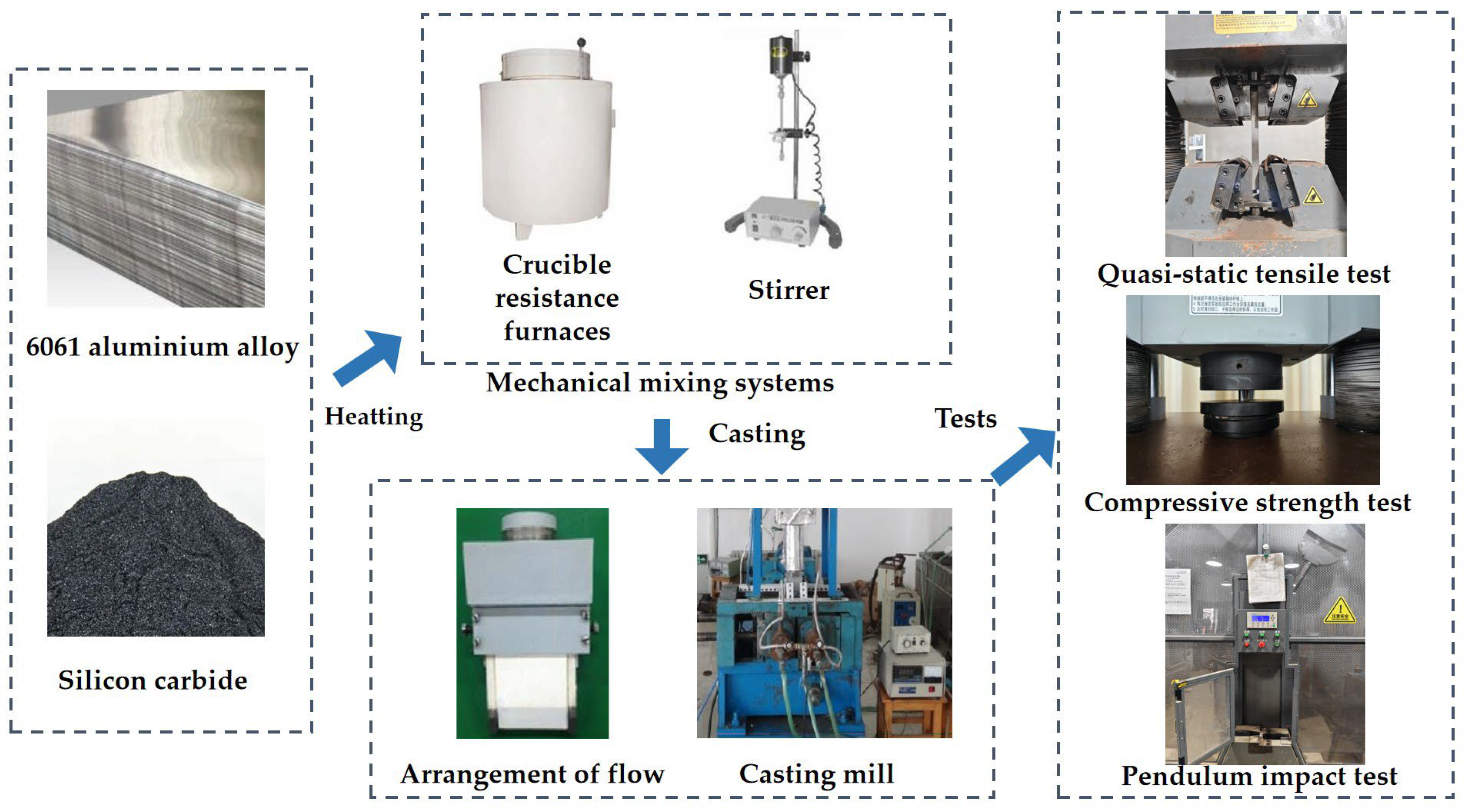
Figure 1. The preparation procedure.
Coatings 14 01472 g001
Figure 2. The dimensions of the specimens.
Coatings 14 01472 g002
Figure 3. The equipment used for the pendulum impact test.
Coatings 14 01472 g003
Figure 4. The aluminum alloy’s yield and ultimate tensile strengths. (a) The yield tensile strength. (b) Decreasing rate of yield tensile strength. (c) The ultimate tensile strength. (d) Decreasing rate of yield ultimate strength.
Coatings 14 01472 g004
Figure 5. The aluminum alloy’s compressive strength. (a) The compressive strength. (b) Decreasing rate of compressive strength.
Coatings 14 01472 g005
Figure 6. The aluminum alloy’s compressive strength (a) before dry–wet alternations; (b) after NaCl dry–wet alternations; (c) after Na2SO4 dry–wet alternations.
Coatings 14 01472 g006
Figure 7. The aluminum alloy’s tensile toughness. (a) The tensile toughness. (b) Decreasing rate of tensile toughness.
Coatings 14 01472 g007
Figure 8. The aluminum alloy’s impact toughness. (a) The impact toughness. (b) Decreasing rate of impact toughness.
Coatings 14 01472 g008
Figure 9. The aluminum alloy’s mass loss rate vs. the mass ratio of SiC after 30 dry–wet alternations with NaCl or Na2SO4 solution.
Coatings 14 01472 g009
Figure 10. The SEM photos of the aluminum alloy with silicon carbide. (a) Specimen with 2% silicon carbide. (b) Specimen with 8% silicon carbide. (c) Specimen with 10% silicon carbide.
Coatings 14 01472 g010
Figure 11. The SEM-EDS photos of the aluminum alloy with silicon carbide. (a) Specimen with 2% silicon carbide. (b) Specimen with 8% silicon carbide. (c) Specimen with 10% silicon carbide.
Coatings 14 01472 g011
Table 1. Composition (by mass fraction) of 6061 aluminum alloy (%).
ElementSiFeCuMnMgCrZnTiAl
Mass percentage0.7580.5690.1700.0180.8050.0470.0310.01597.587
Table 2. Mass fractions of the aluminum alloy (%).
GroupSilicon Carbide6061 Aluminum Alloy
C10%100%
C22%98%
C34%96%
C46%94%
C58%92%
C610%90%
Disclaimer/Publisher’s Note: The statements, opinions and data contained in all publications are solely those of the individual author(s) and contributor(s) and not of MDPI and/or the editor(s). MDPI and/or the editor(s) disclaim responsibility for any injury to people or property resulting from any ideas, methods, instructions or products referred to in the content.