Article

Extended Lifetime of Dual-Layer Yttria-Stabilized Zirconia APS/Gadolinium Zirconate SPS Thermal Barrier Coatings in Furnace Cycle Tests

1
Forschungszentrum Jülich GmbH, Institute of Energy Materials and Devices—Werkstoffsynthese und Herstellungsverfahren (IMD-2), Wilhelm-Johnen-Straße, 52428 Juelich, Germany
2
Jülich Aachen Research Alliance, JARA-Energy, Wilhelm-Johnen-Straße, 52428 Juelich, Germany
3
Institut für Werkstoffe, Ruhr-Universität Bochum, Universitätsstraße 150, 44801 Bochum, Germany
*
Author to whom correspondence should be addressed.
Coatings 2024, 14(12), 1566; https://doi.org/10.3390/coatings14121566
Submission received: 4 November 2024 / Revised: 28 November 2024 / Accepted: 7 December 2024 / Published: 13 December 2024
(This article belongs to the Special Issue Smart Coatings)

Abstract

:
Gadolinium zirconate (Gd2Zr2O7, GZO) has been investigated for two decades as a thermal barrier coating (TBC) material in gas turbines. The advantages of this material over conventional yttria-stabilized zirconia (YSZ) are its lower thermal conductivity, phase stability, and low sintering tendency at elevated temperatures above 1200 °C. However, a major disadvantage is the low fracture toughness of the material and the reaction with the thermally growing oxide layer (TGO). As a result, single-layer GZO coatings cannot be used as TBCs. To overcome these challenges, the present study focuses on the development of double-layer TBC systems, produced with a single gun to keep the manufacturing time low. The respective layers were optimized for specific requirements using a porous atmospheric plasma spray (APS)-YSZ interlayer covered by a suspension plasma sprayed (SPS)-GZO top layer. In furnace cycling tests at 1100 °C, the double-layer systems developed in this study were able to achieve a significant increase in thermal cycle life compared to single-layer APS-YSZ coatings. In addition, the failure mechanism after thermal cycling was investigated, and phase analysis was performed using XRD. The examination of Young’s modulus and the hardness of the layers revealed sintering in the GZO layer due to thermal cycling, while the APS layer showed only minor changes.

1. Introduction

Thermal barrier coatings (TBCs) are a key part of protecting structural components in aircraft and stationary gas turbines for power generation for decades. Their importance results from maximizing the efficiency of gas turbines and minimizing emissions [1,2]. This optimization is realized by increasing combustion temperatures, which today exceed the melting point of the nickel-based superalloys from which the structural turbine components are made [3]. To achieve this, a metallic bond coat and a ceramic top coat are applied to the components in the hot section of the turbine. The metallic bond coat protects against oxidation and provides an adhesive base for the ceramic top coat. The ceramic top coat is the actual thermal insulator [4]. Since this study investigates the ceramic coating, the following discussion will focus on them.
Common manufacturing processes for ceramic coatings include electron beam physical vapor deposition (EB-PVD) [5,6] for the production of columnar structured coatings for aircraft turbines or the atmospheric plasma spraying (APS) process for the production of lamellar structured coatings for large components in aircraft gas turbines, such as the combustion chamber, or in industrial gas turbines [7,8]. Since the late 1970s, zirconia stabilized with 6–8 wt.% yttria (YSZ = yttrium stabilized zirconium) has become an established material [9]. It is characterized by a high melting point (~2700 °C) and a relatively low thermal conductivity of 2.6–2.7 W/mK for fully dense 5.8 wt.% YSZ from RT to 1000 °C [10]. In thermal barrier coatings, however, these values can be reduced to 1.4–1.9 W/mK for EB-PVD coatings and 0.8–1.3 W/mK for APS coatings due to the microstructure of the coatings [10,11,12]. Further advantages are the high coefficient of thermal expansion for an oxide ceramic (CTE 10–11 × 10−6 K−1 [3,13]) and the high fracture toughness (~2 MPa∙m−0.5) [14]. Since the CTE is close to that of the metallic substrate alloy, which is typically temperature dependent and lies in the range of 14–16 × 10−6 K−1 [3,13], the thermally induced stresses due to temperature changes in turbine operation are reduced. Furthermore, the material exhibits excellent thermal stability, withstanding temperatures of at least 1200 °C, thus making it suitable for prolonged operation at this level and, moreover, it may even withstand higher temperatures.
Nevertheless, sintering and the remaining discrepancy in the CTE lead to stress development in the thermal barrier coating during operation. At operating temperature, the stresses build up in the ceramic typically relax at these high temperatures, increasing the compressive stresses in the coating during cooling. If this elastically stored energy exceeds a critical value, cracks can propagate and lead to the spallation of the ceramic [15]. This failure typically occurs in or above the thermally grown oxide layer (TGO, mostly Al2O3), which forms on top of the bond coat at elevated temperatures. The growth of this layer also increases the stresses in the layer due to the increase in volume [16,17].
However, a significant disadvantage of YSZ only occurs at elevated temperatures above 1200 °C. Above these temperatures, the material suffers from accelerated sintering and an undesirable phase transformation. The sintering reduces the porosity and thus the thermal insulation performance [18,19] and increases Young’s modulus of the coating [20], whereby the higher stresses lead to faster coating spalling [13]. The undesired transformation from the tetragonal to the monoclinic phase is associated with an increase in the volume of around 3%–5%, which additionally increases the stresses in the coating [21,22,23]. For this reason, alternative materials are being considered for the thermal barrier top coatings at operating temperatures above 1200 °C.
In the last two decades, pyrochlores have become a research focus for alternative ceramic materials [24,25,26]. These are characterized by an equally high melting point, lower thermal conductivity, low sintering tendency, and phase stability at elevated temperatures [27]. The gadolinium zirconate (Gd2Zr2O7, GZO) used in this study has a melting point of about 2570 °C, which close to that of YSZ [28]. The CTE of GZO (10.5 × 10⁻⁶ K−1) is also similar to that of YSZ [29]. Compared to YSZ, GZO has improved properties due to its lower thermal conductivity (1.2 W/mK in dense material) [30] as well as a low sintering rate and high phase stability at elevated temperatures [31]. At high temperatures around 1530 to 1550 °C, GZO undergoes a transition from the fluorite defect structure (Fm3m) to the pyrochlore structure (Fd3m), but this does not have a detrimental effect on the service life of the coating, as is the case with the volume expansion in YSZ [32,33]. However, GZO also has disadvantages. On the one hand, reactions occur between GZO and the TGO layer. This leads to the formation of a GdAlO3 phase, which consumes the protective oxide layer and can cause an internal oxidation of the bond coat [34,35]. In addition, GZO has a relatively low fracture toughness, leading to crack propagation, even at low stresses in the material. As a result, GZO monolayers have a lower thermal cycling life than YSZ monolayers [36].
To take advantage of the high thermal stability and low thermal conductivity of GZO while avoiding the disadvantages of low fracture toughness and chemical reactivity with the TGO, double-layer systems can be used. Such double-layer systems were introduced by Vaßen et al. They applied a YSZ layer with a high fracture toughness between the bond coat and the GZO top coat to reduce the growth of cracks due to stresses and prevent the detrimental reaction with the TGO layer. With this approach, they were able to increase the service life in burner rig tests compared to single-layer APS coatings or achieve the same service life at around 100 K higher surface temperatures [36].
Bakan et al. and Vaßen et al. reported an extended service life of APS YSZ/GZO double or multilayer systems in gas burner test rigs (1400 °C surface temperature) compared to single-layer APS YSZ coatings. The microstructure and Young’s modulus of the coatings also influence the service life. It has been shown that longer service lives can be achieved for the same cumulative porosity if Young’s modulus of the coatings is lower. Conversely, dense GZO coatings (porosity 10%–11%) lead to premature spalling of the GZO top layer, resulting in faster failure than single-layer APS-YSZ coatings [37]. It has also been observed that at elevated temperatures (1550 °C surface temperature), the main cause of failure of YSZ coatings is not sintering and phase transformation but the high energy release rates at the beginning of a cooling cycle [15]. For this reason, the investigation of coating microstructures with high strain tolerance, such as dense vertically cracked (DVC) or columnar coatings, is of interest.
A study on DVC coatings by Viswanathan et al. has shown that a high Young’s modulus induces early coating failure. In addition, the coating design has a significant influence on the failure mechanism. For example, if the thickness of the tough YSZ layer is sufficient (150 µm in a total coating thickness of 300 µm), the failure location could be shifted from the GZO layer (cohesive failure) to the interface at the TGO (adhesive failure), thereby increasing the lifetime of the coatings [38].
Multilayer systems produced entirely using the SPS process also showed a longer service life than single-layer APS-YSZ coatings in thermal cyclic fatigue tests and gas burner tests [39,40]. Zhou et al. investigated the performance of APS-YSZ/SPS-GZO multilayer systems under burner rig test conditions and showed an improved cyclic lifetime compared to APS-YSZ monolayers [35].
These studies underline the potential of YSZ/GZO multilayer systems at elevated temperatures. In particular, the combination of APS-YSZ and SPS-GZO layers appears to be an interesting approach, as it combines the positive properties of both layers. The lamellar YSZ offers high fracture toughness with a low modulus of elasticity and excellent insulation due to its porous microcracked structure. The GZO layer, on the other hand, can be deposited in a DVC or columnar structure using the SPS process, giving it a high strain tolerance. This type of coating design is examined in more detail in this study, taking the thermal cyclability in furnace tests into account. Furthermore, the goal is to deposit both ceramic layers with a single torch on a single production system. From an industrial point of view, this is an important opportunity to minimize setup costs and times. Furthermore, such a coating system has not been tested in furnace cycle tests, which results in higher cumulative stresses than gradient tests due to the different thermal expansions of the coatings. Therefore, this test is a particularly suitable way of investigating the strain tolerance of the coating systems examined in this study.

2. Experimental Methods

2.1. Materials of Ceramic Coatings

To produce the double-layer TBC, an 8YSZ powder and a GZO suspension were used to create the desired coating microstructures. The YSZ interlayer was produced with the commercial powder Metco 204NS (Oerlikon Metco, Wohlen, Switzerland). It is a HOSP powder with the particle size distribution (PSD) shown in Table 1 and the chemical composition given in Table 2. The GZO top coat was produced using a non-commercial suspension from the research and development department of Oerlikon Metco, Westbury, USA. This was a suspension with a solid content of 25 wt.% mixed with ethanol. The chemical composition of the GZO powder is shown in Table 2. This powder is milled for the suspension to the PSD specified in Table 1. The fine particle size distribution of the suspension is necessary to produce columnar coatings. The GZO suspension is listed at Oerlikon Metco with the research number AE12088 and is to be launched later this year as a commercial product.

2.2. Sample Preparation

For furnace thermal cycling tests and the results described in this study, button-shaped Inconel738 substrates (diameter 30 mm, thickness 3 mm) with rounded outer edges were used to reduce the stress level and avoid failure at the edges. The substrates were coated with an approximately 200 µm thick CoNiCrAlY Amdry9954 bond coat using the HVOF process. The metallic bond coat was applied using a Diamond Jet DJ spray gun (Oerlikon Metco) on a MultiCoat system (Oerlikon Metco, Wohlen, Switzerland). Prior to further processing, the cycling buttons were annealed under vacuum at 1120 °C for 2 h and at 845 °C for 24 h. This diffusion bonding improves the bond between the substrate and the bond coat. In addition, it allows an Al-rich β-phase to precipitate, which acts as an aluminum reservoir for Al2O3 TGO formation.
The two ceramic top layers were also produced on the MultiCoat system using a TriplexProTM 210 three-cathode cascaded gun (Oerlikon Metco). In the APS process, the powder was radially injected into the plasma. The short injector mount and a 1.8 mm diameter injector were used. The short injector mount was also used in the SPS process. For the SPS process, however, a feeding system developed by Forschungszentrum Jülich GmbH, Germany, was used to feed the suspension to the torch. In this system, the suspension is fed to the torch from a tank using overpressure [42]. As a result, the feed rate is determined by the pressure in the tank. The suspension was then radially injected into the plasma using 120 µm diameter continuous stream injection nozzles without atomization (Oerlikon Metco). Both ceramic layers were applied with a thickness of around 200 µm each.
Three different APS interlayers were used to investigate the effect of their surface roughness on the SPS-GZO microstructure. The manufacturing parameters are shown in Table 3. On the one hand, APS layers were produced with spray parameters that generate a relatively high porosity and have already been used in many studies on thermal cycling (APS1) [43]. For the other surface structures, the same parameters as for APS1 were used for the first layers to guarantee the same thermal insulation and fracture toughness. However, the parameters were adjusted for the last four passes. For one parameter set, the last layers were produced with increased deposition temperatures to produce a smooth APS-YSZ surface. Therefore, the power output of the torch was increased by raising the current to 500 A. Furthermore, the spraying distance was decreased to reduce the particles cooling in flight, so a dense and smooth coating can be produced (APS2). In the other parameter set, the current was reduced for the last four passes. The cooler deposition conditions should cause the particles to melt less and flatten less on impact with the substrate, resulting in increased roughness (APS3).
The parameters in Table 4 were used for the GZO top layers. These generate the same torch output power with different process gas fluxes and current densities (~47 kW). The different process gas flows were used to evaluate their influence on the atomization of the radially injected suspension. The amount of plasma gas affects the atomization of the suspension and thus the droplet size. This is particularly important when the suspension is injected radially into the plasma, as no additional gas is used for atomization. The size of the droplets, in turn, affects their trajectory, which has an effect on the microstructure of the resulting coatings 45, 46, and 47. The GZO LP parameter has a lower process gas flow, reducing the atomization of the suspension and thus affecting the resulting microstructure. The GZO HP instead uses the high-process gas flow. The feed pressure was set to 1.5 bar, resulting in an average total feed rate of 47.6 ± 10.2 g/min, corresponding to a solids content of 11.9 ± 2.5 g/min.
With these parameters, six different coating systems could be produced. These were evaluated on the basis of the resulting coating microstructures, and four promising coating systems were then selected for thermal cycling tests in a furnace.

2.3. Characterization

Metallographic cross-sections were prepared from all samples produced in this study. These were examined by scanning electron microscopy (Hitachi TM3000, (Hitachi Hightechnologies Europe GmbH, Krefeld, Germany) or Gemini SEM 450 (Carl Zeiss AG, Oberkochen, Germany)). The general microstructure (porous, densely vertically cracked, columnar) and its microstructural properties (porosity, defects, crack/columnar density) were examined. The porosity of the APS coatings was measured with ten images each at 1000× magnification, and the porosity of the SPS coatings within the columns was measured with ten images, each at 2000× magnification. The crack and column density were determined from stitched images over a distance of approximately 5 mm. The coating thickness was measured at 20 different points along this length. The coating systems cycled in the furnace were analyzed both as sprayed and after thermal exposure to determine the failure mechanism and the thickness of the thermally grown oxide layer after cycling. The TGO thickness was determined from 150 measurements per sample on a total of 10 different images. Fiji software (1.54g) was used for the image analysis of all the measurements presented here.
The surface properties of the three different APS-YSZ interlayers were determined using a confocal laser microscope (VK9700, Keyence, Neu-Isenburg, Germany) and a white light topographer (Profilometer CT 350T, Cyber Technologies, Eching, Germany). The laser microscope images were taken at 20× magnification, and the surface roughness of three sample surfaces per coating system was determined in the x- and y-directions using the white light topographer.
In addition, X-ray diffraction was used to determine the phase composition of the suspension powder and the GZO coatings before and after thermal exposure. A Bruker AXS D4 Endeavor was used with CuKα radiation. The 2θ range was set from 10° to 80° with a step size of 0.02° and a counting time of 0.75 s/step.
The mechanical properties of the coatings determined in this study are hardness and Young’s modulus, which are important properties of TBCs. These were also determined on the cross-sections for the ceramic coatings before and after thermal exposure. The measurements were made using a Vickers H-100 Fischerscope microindenter (Helmut Fischer GmbH, Sindelfingen, Germany). The Enhanced Stiffness Procedure (ESP), in which the indenter is progressively loaded and unloaded, was used. In this procedure, 8 load steps were used, with 50% relief after each step before the next higher load was applied. A maximum load of 500 mN was defined. This method can determine the elastic indentation modulus EIT, Vickers hardness HV, and indentation hardness HIT for different load ranges at the same specimen location. For each sample, seven indentations were made in the APS and SPS layers.

2.4. Furnace Cycling Tests

In this study, the furnace cycling test was preferred to the thermal cycling with temperature gradient in the burner rig. The reason for this is that the furnace cycling test produces higher accumulated stresses due to the thermal expansion mismatch. Therefore, the strain tolerance of the coating systems investigated in this study can be examined particularly well. The furnace cycling was performed in the air in an SPLF 12882 furnace (Fa. Carbolite). The heating cycle lasted for 120 min at 1100 °C. Then, the samples were removed from the furnace and cooled in air with a fan for 15 min. The failure criterion for the coating was defined as 30% or more spallation of the ceramic coatings. As it is an automated process, samples were reviewed for failure every 20 cycles. In addition to the double-layer systems, single-layer APS-YSZ coatings were also tested as a reference. These APS-YSZ coatings were deposited using the APS1 parameters described above, with no changes to the settings during the process. A total of three samples from each of the bilayer systems and two APS monolayer samples were tested.

3. Results and Discussion

3.1. Microstructure of As-Sprayed Double-Layer Systems

The coating microstructures of the six samples, produced with the different APS and SPS parameters, are shown in Figure 1. These show different coating microstructures, especially in the SPS-GZO layers. According to these, the influence of the investigated parameters is analyzed. Furthermore, tests were carried out on the three different APS surfaces for detailed analysis.
The APS coating’s surface roughness was analyzed using the white light topographer. The standard APS-YSZ (APS1) coating without a modified surface showed an Ra value of 9.4 ± 0.4 µm. The APS coatings deposited with the reduced torch power (APS3) had a comparable value of Ra = 9.5 ± 0.4 µm. By increasing the torch power (APS2), however, the roughness value could be reduced to Ra = 7.6 ± 0.1 µm.
In addition to the roughness measurements, images of the surface topographies were taken with the confocal laser microscope. Joeris et al. and Zhou et al. showed that even with comparable Ra values, different SPS microstructures can form with different topographies of the underlying surface. They found an increased column density with a higher number of roughness peaks [44]. The confocal laser microscope images showed a more uniform surface on the high-power deposited APS2 coating (Figure 2b) compared to the unmodified APS1 coating (Figure 2a). This correlates with the lower Ra value. The elevations in the profile of the APS2 coating have a more spherical surface with fewer roughness peaks. A comparison between the unmodified coating APS1 and the reduced-power coating APS3 shows no significant differences in the Ra values.
On top of the different APS interlayers, different SPS-GZO microstructures were formed. With the smoother APS2 interlayer, column formation was almost non-existent, as shown in Figure 1c,d. This is because the low number and rounded shape of the peaks inhibit column formation since the fine particles carried by the plasma gas stream deflected in front of the substrate cannot deposit laterally on these roughness peaks [45]. Furthermore, in the case of the smoother APS-YSZ interlayer, vertical cracks form in the coatings. Due to the small number of microcracks in the coating, tensile stresses build up as the splats cool down after impact, leading to the formation of segmentation cracks [46]. Coatings with segmentation cracks are also suitable for strain-tolerant coatings. However, in this case, the vertical cracks are combined with horizontal cracks along the interpass porosity of the coatings, especially in the SPS coating with the high-process gas fluxes. These horizontal cracks originating from the vertical cracks are also referred to in the literature as branching cracks. They have been observed in a large number of studies, [44,47,48]. To better visualize the formation of the horizontal cracks, images (c) and (d) in Figure 1 were shown at a higher magnification. Comparing the occurrence of these cracks, it is noticeable that they always appear in coatings deposited on rather smooth substrates. In addition, they always grow in the porous interlayers of the SPS GZO coatings. Deposition on the smooth surfaces results in the formation of DVC structures, which also have a uniform top coat surface without large differences in height. Therefore, the porosity bands run parallel to the interface and are not waved, providing an easy path for crack propagation. In addition to the poor bonding of the coatings within the porosity bands, the low fracture toughness of GZO can also affect crack propagation within the coating. The branching cracks can have a negative effect on the thermal cycling capability of the coating. Therefore, it was decided to produce the cycling samples only with the APS1 and APS3 interlayers.

3.2. Microstructure of Thermal Cycling Samples in the As-Sprayed Condition

For furnace cycling tests, a total of four combinations of APS-YSZ and SPS-GZO were produced. The as-sprayed microstructures are shown in Figure 1a,b,e,f, and Table 5 shows the parameters used to produce the different dual-layer systems and the resulting coating thicknesses. In this table, there is also a name given for each of the systems, which will be used in the following. System A consists of the standard APS1 interlayer and the GZO LP layer produced with the low-process gas flow. System B also consists of the standard APS1 layer and the GZO HP produced with the high-process gas flow. Systems C and D consist of the reduced-power APS3 layer and the low- (GZO LP) and high-process gas flow (GZO HP) top layers, respectively. All of the ceramic layers produced have a comparable thickness. The porosity of the YSZ interlayers is approximately 14.6 ± 0.9% in all systems. No effect of the parameter variation on the porosity could be determined, as most of the layers were sprayed with the APS1 parameter. In contrast, an effect of the process parameters on the porosity could be determined for the SPS-GZO coatings. For the low-process gas flux coatings (GZO LP), the porosity within the columns was higher, with a value of 11.1 ± 1.4%, than for the high-process gas flux coatings (GZO HP), where the porosity value was 8.8 ± 0.8%.
The higher density of the GZO HP coatings might be due to the faster melting of the particles, which can be explained by the atomization of the suspension droplets into finer particles in the faster plasma due to the higher gas flow. This results in smaller agglomerates that melt faster. This effect is in contrast to the shorter dwell time of the particles in the hot plasma, whereby the finer atomization seems to have the greater effect.
As expected, columns grew on the roughness peaks. In contrast, vertical cracks formed in areas with few roughness peaks (Figure 1). The microstructures of the samples always contained a mixture of columnar and vertical cracked structures. Therefore, all cracks and gaps in the columnar microstructure were counted to determine the crack and column density. Overall, the crack and column densities measured in the systems ranged from 9 to 11 mm−1, which is not a large difference.
The APS reference system had a porosity of about 14%, as well as the APS interlayer of the double-layer systems. However, the coating thickness of the monolayer system was slightly lower at 382.3 ± 17.0 µm.

3.3. Furnace Cycling

3.3.1. Coating Lifetime

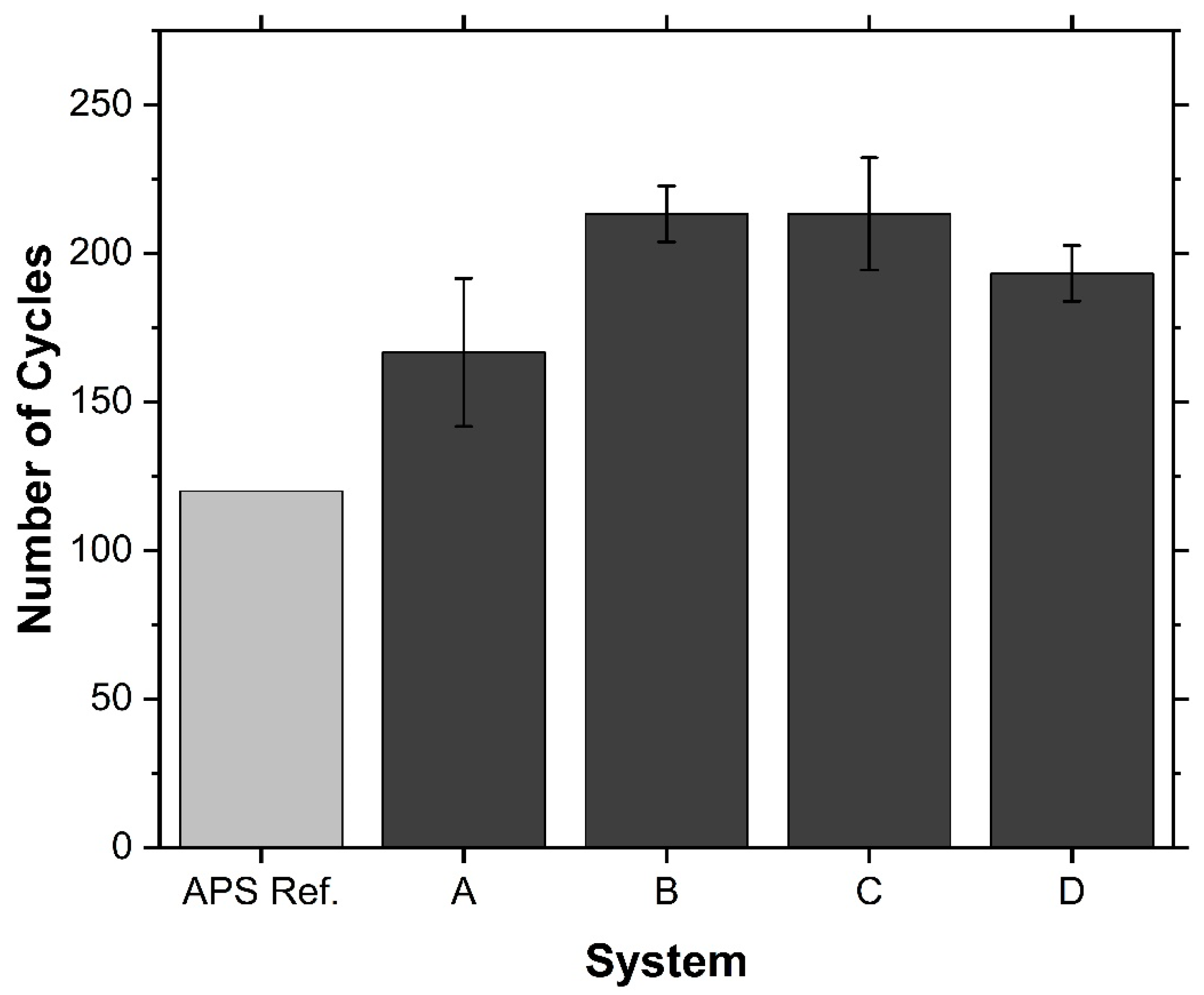
The lifetime of the different coating systems in the furnace cycling tests is shown in Figure 3. The values used in the graph are always the number of cycles after which the system was still intact. Failure then occurred within the next 20 cycles. The figure shows that all double-layer systems had a longer lifetime than the APS reference coatings. The two APS-YSZ monolayer reference coatings both failed between 120 and 140 cycles. System A had a lifetime of 166.7 ± 24.9 cycles, system B had a lifetime of 213.3 ± 9.4 cycles, system C had a lifetime of 213.3 ± 18.9 cycles, and system D had a lifetime of 193.3 ± 9.4 cycles. The best performance was achieved by a sample from system C, which was still intact after 240 cycles. This represents a doubling of the lifetime compared to the reference coatings. It also needs to be noted that the coating thicknesses of the double-layer systems were higher than those of the reference system. This increases the elastic energy stored in the ceramic caused by thermal cycling, which promotes spalling of the ceramic. The mixture of segmentation cracks and columns within the SPS-GZO top coat seems, therefore, to reduce the amount of elastically stored energy in the coating, increasing the cyclability.
However, based on these experimental data, it is not possible to interpret the effects of the APS surface and the GZO microstructure on lifetime separately. Further testing would be required to determine which has the most significant effect on lifetime. Nevertheless, it can be stated that the two-layer structure of lamellar, porous YSZ intermediate layer and columnar/vertical cracked GZO top layer prolongs the life of TBCs in furnace cycling tests and also at intermediate temperatures.

3.3.2. Failure Mode

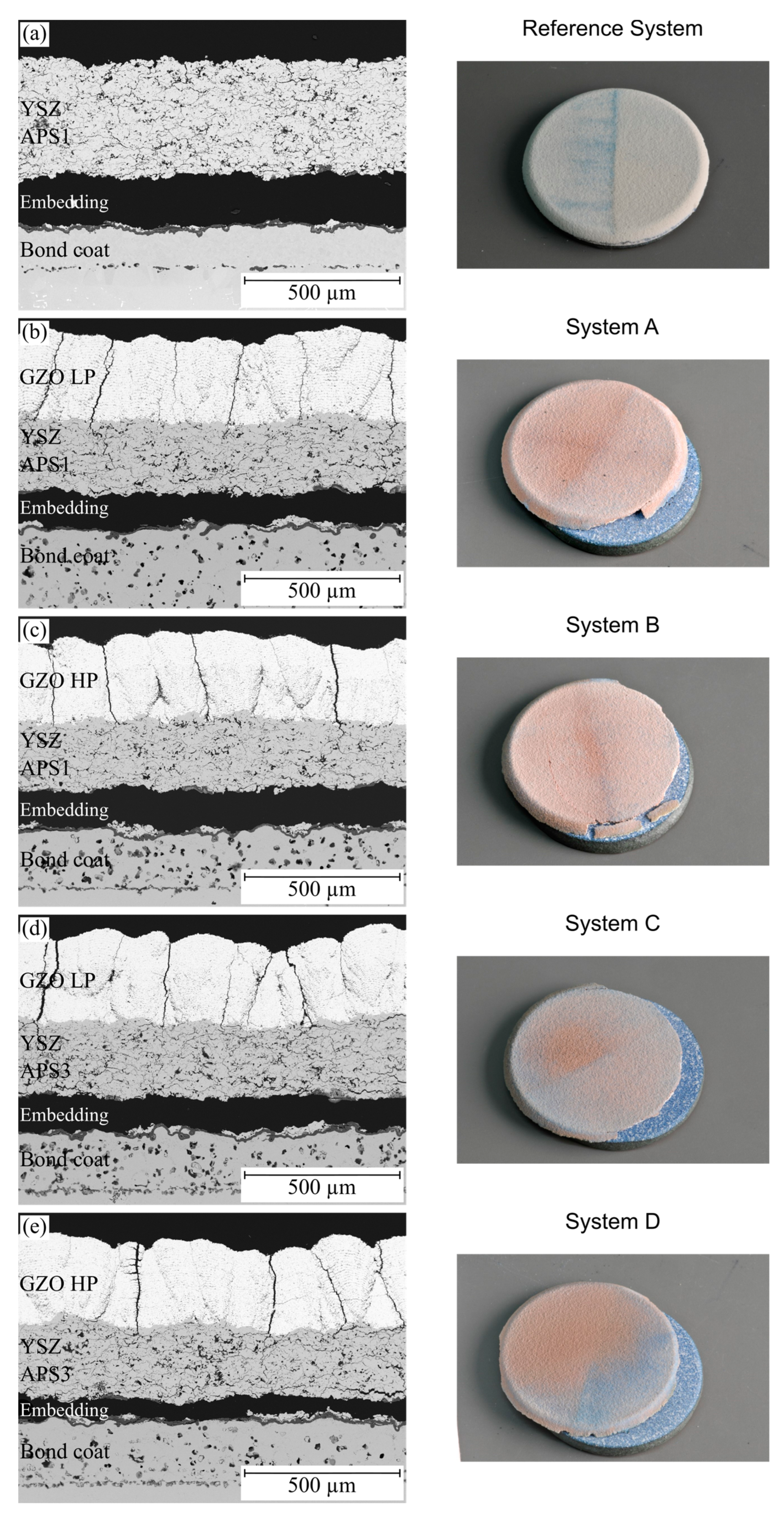
The cracks leading to failure of the APS monolayer systems propagated in the ceramic near the TGO, in the TGO itself, or between the TGO and the top or bond coat, as shown in Figure 4a. A mixture of these three localization zones was present in both reference samples. In both cases, nearly the entire coating detached from the bond coat and the substrate. The thickness of the TGO was 9.0 ± 2.2 µm. This Al2O3 layer was formed from the Al-rich phase of the bond coat and led to a depletion of the bond coat near the TGO. In addition, yttrium oxides were found in the Al2O3 film, and spinels grew on the TGO. However, small amounts of the β-phase were preserved in the bond coat. The porosity of the ceramic layer remained almost unchanged at 13.5 ± 1.4%.
The cross-sections in Figure 4 also show that the double-layer concept is effective in preventing crack propagation. The vertical cracks present in the as-sprayed GZO expand to the interface at the APS-YSZ layer. But, when these cracks encounter YSZ with its high fracture toughness, their growth is directly inhibited, and the cracks do not propagate further. In addition, no cracks were found at the interface between YSZ and GZO, indicating good bonding between the APS and SPS layers. In the GZO layer, some horizontal cracks were formed, which originated from the vertical cracks and ran through the porous areas between the layers of the GZO coating (Figure 4d). However, no part of the GZO top coat ever spalled off.
The twelve double-layer specimens all showed the same failure mode as the two reference samples. SEM cross-sections and photographs of a failed sample of each system are shown in Figure 4. Again, in all samples, the entire coating at the interface between the bond and top coat spalled off. There was no significant difference in the thickness of the oxide layer, even though the bilayer systems had longer lifetimes than the samples of the reference system. The thickness of the TGO layers for systems A to D was 8.7 ± 3.6 µm, 8.4 ±3.4 µm, 8.0 ± 3.3 µm, and 8.2 ± 3.6 µm, respectively. Nevertheless, the trend is even below the TGO thickness of the reference monolayer system. The measured error, on the other hand, is higher for the double layers.
A possible explanation for this is that the oxide layer grows rapidly at the beginning of thermal cycling but then forms a dense oxygen diffusion barrier, causing the oxide layer to continue to grow slowly. Therefore, the thickness difference is low, even though the service life differed significantly. Another explanation is that the bond coat of the reference system is already almost completely depleted of the aluminum-rich β-phase, which means that hardly any aluminum is available for the formation of the Al2O3 TGO, and thus it cannot grow beyond the thickness identified here. This indicates that the oxide thickness is not the driving force of failure of the coating systems. It is suggested that the increased lifetime of the bilayer systems is due to the increased strain tolerance of the bilayer composite. In addition to the Al2O3 layer, more oxide layers with a lighter color were identified in the cross-sections of the dual layer compared to the spinels in the reference systems; these are Co, Cr, and Ni spinels. Their growth indicates an Al depletion in the bond coat due to TGO formation, as these typically form when the Al content in the bond coat has dropped below a critical value [49]. This is confirmed by the fact that no Al-rich β-phase could be observed in the bond coat.
In addition, dispersed pores formed in the bond coat layer of the double-layer systems. This phenomenon, known as Kirkendall porosity, occurs when the bond coat is depleted of alloying elements due to TGO growth and interdiffusion typically during long-term operation. The different diffusion coefficients of the alloying elements lead to the accumulation of vacancies that grow into pores [50,51]. Since these pores often occur at the interface between the substrate and the bond coat, as shown in the cross-sections in Figure 4, they compromise the adhesion of the coating and can lead to failure [52].
However, there are also pores that, contrary to the assumption, have formed in the middle of the bond coat or even in the area near the TGO. Therefore, it must be clarified how the pores are formed there. To investigate a possible loss of material in the bond coat, EDX point measurements were taken before and after furnace cycling at a bond coat of a double-layer system. The measured points are marked in Figure 5 for the as-sprayed state in (a) and for the cycled state in (b). The area investigated was in the middle of the bond coats. The respective measured values of the spectra are listed in Table 6. In the left image (a), the β-phase is clearly visible. This is also reflected in the measured values. In the dark β-phases (Spectrum 3–5), the Al concentration of ~12 wt.% is higher than in the light-colored matrix, where the Al concentration is only 7 wt.%. The calculation of the mean values of the individual point measurements leads to a composition of Co 32Ni 21Cr 9Al 0.1Y wt.%. To validate the mean values calculated from the point measurements, two EDX mappings were also carried out to determine the phase fractions over larger bond coat areas of the sample in the as-sprayed state. The mean values of the samples from the point measurements correspond well with the mean values of the mappings, which are also given in Table 6 (Map1&2). In addition, the values determined with the EDX are within the composition ranges specified in the alloy datasheet.
The Al concentration decreases as expected during thermal cycling due to the formation of Al2O3. Therefore, it is, on average, around 4 wt.% after cycling instead of the ~9 wt.% in the as-sprayed state. However, it is also noticeable that there is a considerable loss of Co. The main element of the alloy, which was present at around 38 wt.% in the as-sprayed state, is only present at around 33 wt.% in the bond coat after thermal cycling. The different contrasts in the SEM image do not appear to represent different phases, but crystal orientation contrasts, as all the measured values are very similar. Due to the loss of Co, the relative proportions of Cr and Ni increase, and Ni becomes the main component of the bond coat.
Even if the results of a quantitative EDX analysis must be treated with caution due to a high error probability with inhomogeneous material compositions, a cobalt loss caused by thermal cycling can be clearly identified on the basis of the measurements, in addition to the aluminum loss. However, exact quantification is not possible. Furthermore, at the time, it was not yet clear how the cobalt reduction occurred. Cobalt can either diffuse towards the substrate or towards the TGO and form spinels there. An indication of upward diffusion is provided on the one hand by the spinels found above the TGO and on the other hand by a blue coloring on top of the furnace-cycled samples after failure, which is attributed to co-oxides. However, no SEM images or EDX measurements were taken of the surface before embedding in epoxy. The surfaces were only analyzed with XRD after cycling. No oxide peaks could be identified with this technique, as they are below the detection limit, if present. No oxide deposits on the surface can be seen in the cross-sections in the SEM either. The reason for the loss of the cobalt is, therefore, not clear, but it is seen as a possible cause of the pore formation, which should be investigated in further tests.

3.4. Phase Composition

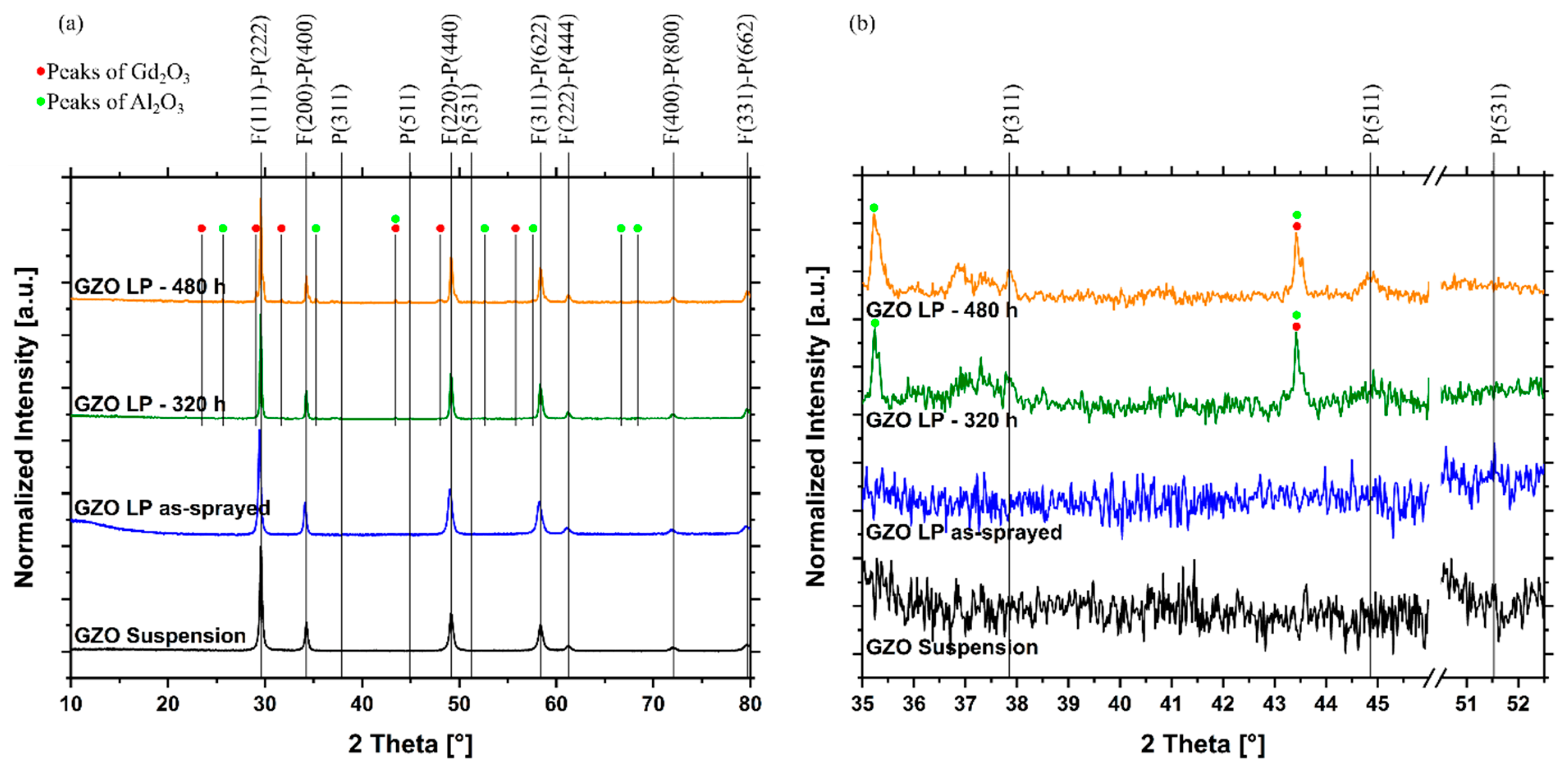
The XRD diffractograms of the powder from the dried suspension, one GZO layer after spraying, and two GZO layers after cycling are shown in Figure 6. In this figure, the measurements on samples produced with the GZO LP parameter are compared. The measurements on the raw powder and the sprayed coating do not show any characteristic pyrochlore peaks (331, 511, 531, etc.), indicating the presence of a defective fluorite phase. The rearrangement of the GZO pyrochlore phase to the metastable defect fluorite phase during plasma spraying has been reported in other studies [36,37]. The rapid cooling of the molten particles on the cool substrate prevents the formation of the ordered pyrochlore structure, resulting in the metastable defect fluorite phase. However, in the studies mentioned above, the powder itself was present in the ordered pyrochlore structure, which is not the case for the suspension used in this study. This is probably due to the manufacturing process of the powder used in the suspension.
After thermal cycling, slight peaks are present in the measurements at the locations characteristic of the pyrochlore phase, indicating the transformation of some of the fluoride phase into the pyrochlore phase (Figure 6b). However, these peaks are very small and may indicate only a slow transition rate due to temperatures of only 1100 °C during cycling. The main phase, nevertheless, is still present as defect fluorite. However, the amount of the transformed phase is not of great importance, as it is not associated with a significant change in the volume or thermal conductivity of the material [53]. Therefore, the phase transformation is not expected to affect the cycling lifetime of the coatings. In addition to the peaks of the pyrochlore phase, other secondary peaks occurred in the cycled samples. These are the peaks marked with the red and green dots, which were identified as Gd2O3 and Al2O3 (Figure 6a,b). Al2O3 originates from a deposit of the sample holder, which is made of this material.

3.5. Change in Microstructural and Mechanical Properties by Thermal Exposure

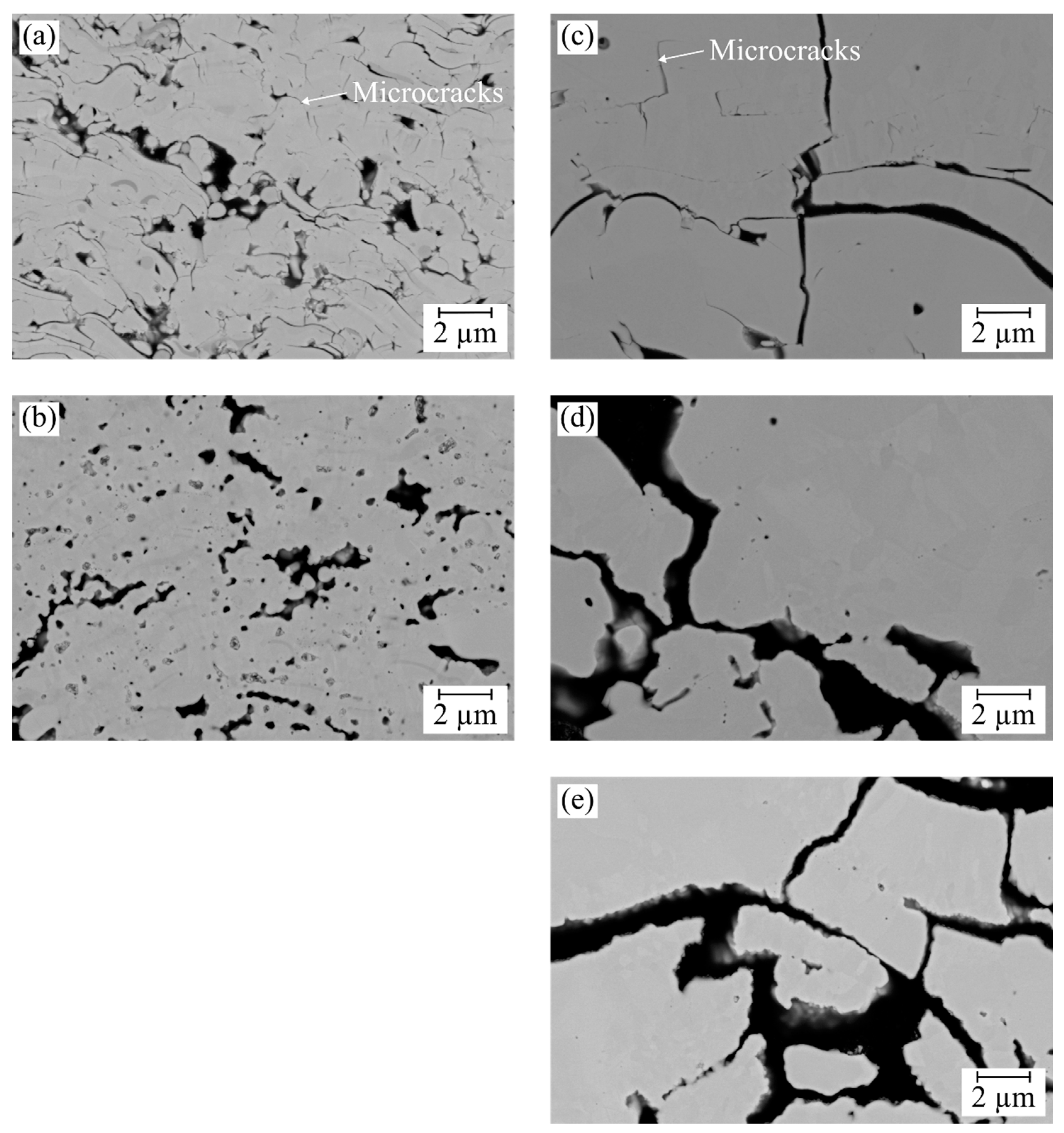
Sintering the material at 1100 °C resulted in changes in the layer microstructures, mainly affecting GZO. The APS coatings did not change and maintained a porosity of 14.2 ± 1.4%. For GZO, the porosity values for the low gas flow deposited layers (GZO LP) decreased from 11.1 ± 1.4% to 9.0 ± 1.3%, and the high gas flow deposited layers (GZO HP) decreased from 8.8 ± 0.8% to 8.0 ± 1.0%. Since the GZO material is considered to have a lower sintering tendency [31], the microstructural effect dominates the sintering of the materials. This effect can also be seen in the high-magnification images of the respective layers of the coatings before and after cycling in Figure 7. In the as-sprayed state, a large number of finely distributed microcracks can be seen in the GZO layer (a). After thermal cycling, these are closed due to the sintering processes, and some larger pores remain (b). In the APS layers instead, only a few of the very fine microcracks are present in the as-sprayed coating, and there are some wider cracks between the dense regions (c). After thermal cycling, the few fine microcracks disappear, but the large cracks are not closed as a result of sintering. A change in the crack surface can be seen, but no bonding between the separated areas is formed.
Another visual indication of a change in the GZO top layer is the width of the cracks in the cross-sections after thermal cycling. Compared to the cracks and gaps next to the columns of the samples in the as-sprayed state (Figure 1), these are significantly wider after thermal cycling (Figure 4). This indicates a shrinkage and densification of the segments between the cracks, causing the gaps to grow.
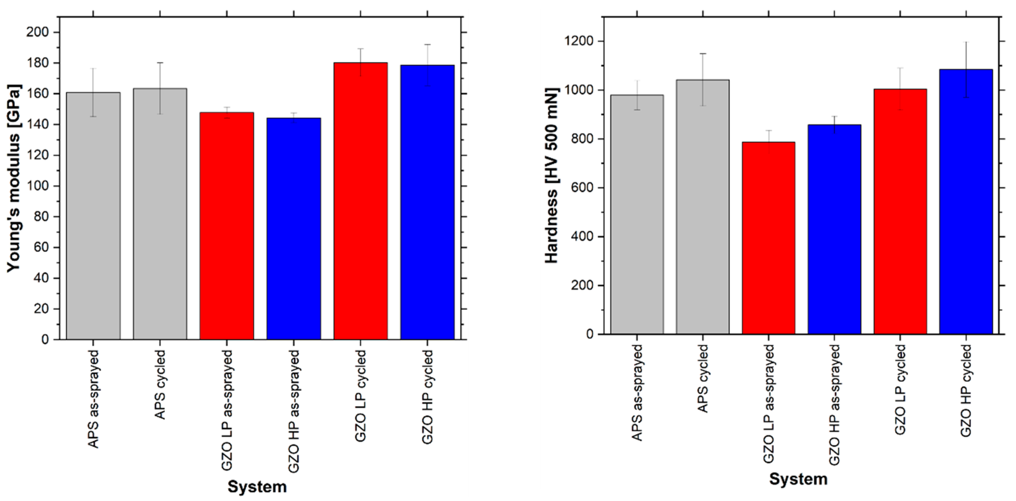
This change due to sintering is also reflected in the mechanical properties of the coatings. Young’s modulus measurements in Figure 8 also show an effect of the heat treatment on the GZO layer. Young’s modulus value has increased by about 30 to 40 GPa on average in all systems. This increase raises the stress level in the coating systems during thermal cycling. However, a direct influence of the process parameters used and the resulting coating microstructures cannot be deduced from this measurement. In contrast, as with the porosity measurements, the APS coatings show no significant change in Young’s modulus due to thermal cycling.
This behavior is also shown in the hardness measurements shown in Figure 8, as the hardness only increased significantly in the GZO layers as a result of thermal exposure. It can, therefore, be concluded that contrary to the assumption of a generally higher sintering tendency of YSZ, changes only occurred in the GZO as a result of the heat treatment. These findings are consistent with the results of Frommherz et al. They showed for APS-GZO structures that GZO sintered more than YSZ at 1100 °C. At 1300 °C, on the other hand, GZO showed a lower sintering tendency than YSZ. The authors were able to explain this by the specific microstructure of the GZO layers, which, in their case, had a higher defect density than YSZ [54].

4. Conclusions

In this study, double-layer APS-YSZ/SPS-GZO TBCs were developed and deposited. A special focus has been put on the deposition of strain-tolerant GZO top layers. The microstructures, mechanical properties, and thermal cycling resistance of the TBC systems were investigated and compared with a reference system. The main conclusions are as follows:
  • The developed GZO suspension and the radial injection of the suspension by nozzles without atomization allow for the manufacture of a double-layer system with a single plasma torch in one facility. Different microstructures can be produced in this way. The APS-YSZ layers were deposited with a porous lamellar structure, and the SPS-GZO layers were deposited with a strain-tolerant columnar and vertically cracked microstructure. In the future, it may be possible to produce such double-layer systems in a single coating run without modifying the hardware, which is interesting from an economic point of view. In addition, the performance of gas turbines can be improved with the developed coating systems. The GZO top coat allows for very high combustion temperatures due to the high phase stability, and the combination of microstructures enables flexible operation of the turbines with fast-changing loads.
  • The columnar and vertically cracked GZO top layers showed good cyclability and, in the best case, doubled the lifetime compared to the reference system. This is due to the high strain tolerance of the top layer combined with the high fracture toughness of the ceramic interlayer.
  • A change in the microstructure and mechanical properties due to the heat treatment in the furnace test can be observed especially in the GZO layer, which should have a higher sintering resistance than the APS-YSZ layer. This can be explained by the different microstructures produced by the two processes. The much finer distributed porosity in the SPS-GZO layer seems to have a significant influence on the material change during heat treatment.
For further studies, it is proposed to also test these coatings in gas burner rig tests to investigate the performance at high temperatures of ≥1400 °C with a thermal gradient. This more closely simulates the actual conditions in a turbine, although the thermal stresses after cooling down are not as extreme as in the furnace tests. In addition, the benefit of the high phase stability of the GZO coatings can be tested at these temperatures.

Author Contributions

Conceptualization, J.I. and R.V.; Methodology, J.I.; Formal analysis, J.I. and D.E.M.; Investigation, J.I., R.A.R. and D.E.M.; Data curation, R.A.R.; Writing—original draft, J.I.; Writing—review & editing, R.A.R., D.E.M., O.G. and R.V.; Visualization, J.I.; Supervision, R.V.; Project administra-tion, R.V.; Funding acquisition, J.I. and R.V. All authors have read and agreed to the published version of the manuscript.

Funding

This research was funded by the Federal Ministry of Economic Affairs and Climate Action (BMWK), Germany, within the framework of the 7th Energy Research Program with the grant number FKZ 03EE5045A. In addition, parts of the research from this study were funded by the MatKat-Foundation, which supported the first author of this study with a grant under the registration number ArL LG.06-11741/526.

Institutional Review Board Statement

Not applicable.

Informed Consent Statement

Not applicable.

Data Availability Statement

If you wish to view additional data, please contact the authors of this manuscript.

Acknowledgments

This work is part of the LaBeGa project, which was funded by the Federal Ministry of Economic Affairs and Climate Action (BMWK), Germany, within the framework of the 7th Energy Research Program (FKZ 03EE5045A). In addition, parts of the research from this study were funded by the MatKat-Foundation, which supported the first author of this study with a grant under registration number ArL LG.06-11741/526. Furthermore, the authors would like to thank the project partners Oerlikon Metco WOKA GmbH and Oerlikon Metco Surface Solutions, USA, for providing materials. Furthermore, the authors would like to thank the following employees of the institute for their support: Karl-Heinz Rauwald, Frank Kurze, and Ralf Laufs for the production of the coatings, Martin Tandler for his support regarding the furnace cycling tests, and Doris Sebold for some of the SEM images and EDX measurements. We would also like to thank Jürgen Gross from IEK-2 at Forschungszentrum Jülich GmbH for his support in performing the indentation tests.

Conflicts of Interest

Authors Jens Igel, Raseem Ahmed Razak, Daniel Emil Mack, Olivier Guillon and Robert Vaßen were employed by the company Forschungszentrum Jülich GmbH. The remaining authors declare that the research was conducted in the absence of any commercial or financial relationships that could be construed as a potential conflict of interest.

References

  1. Mehta, A.; Vasudev, H.; Singh, S. Recent developments in the designing of deposition of thermal barrier coatings—A review. Mater. Today Proc. 2020, 26, 1336–1342. [Google Scholar] [CrossRef]
  2. Feuerstein, A.; Knapp, J.; Taylor, T.; Ashary, A.; Bolcavage, A.; Hitchman, N. Technical and Economical Aspects of Current Thermal Barrier Coating Systems for Gas Turbine Engines by Thermal Spray and EBPVD: A Review. J. Therm. Spray Technol. 2008, 17, 199–213. [Google Scholar] [CrossRef]
  3. Padture, N.P.; Gell, M.; Jordan, E.H. Thermal barrier coatings for gas-turbine engine applications. Science 2002, 296, 280–284. [Google Scholar] [CrossRef]
  4. Clarke, D.R.; Oechsner, M.; Padture, N.P. Thermal-barrier coatings for more efficient gas-turbine engines. MRS Bull. 2012, 37, 891–898. [Google Scholar] [CrossRef]
  5. Maricocchi, A.; Barz, A.; Wortman, D. PVD TBC Experience on GE Aircraft Engines. In Thermal Barrier Coating Workshop; NASA Conference Publication: Leveland, OH, USA, 1995; pp. 79–90. [Google Scholar]
  6. Rigney, D.V.; Viguie, R.; Wortman, D.J.; Skelly, D.W. PVD thermal barrier coating applications and process development for aircraft engines. J. Therm. Spray Technol. 1997, 6, 167–175. [Google Scholar] [CrossRef]
  7. Clarke, D.R.; Levi, C.G. Materials Design for the Next Generation Thermal Barrier Coatings. Annu. Rev. Mater. Res. 2003, 33, 383–417. [Google Scholar] [CrossRef]
  8. Bernard, B.; Quet, A.; Bianchi, L.; Joulia, A.; Malié, A.; Schick, V.; Rémy, B. Thermal insulation properties of YSZ coatings: Suspension Plasma Spraying (SPS) versus Electron Beam Physical Vapor Deposition (EB-PVD) and Atmospheric Plasma Spraying (APS). Surf. Coat. Technol. 2017, 318, 122–128. [Google Scholar] [CrossRef]
  9. Stecura, S. Effects of Compositional Changes on the Performance of a Thermal Barrier Coating System. Technical Report, NASA TM-78976; National Aeronautics and Space Administration: Cleveland, OH, USA, 1978. [Google Scholar]
  10. Raghavan, S.; Wang, H.; Dinwiddie, R.B.; Porter, W.D.; Mayo, M.J. The effect of grain size, porosity and yttria content on the thermal conductivity of nanocrystalline zirconia. Scr. Mater. 1998, 39, 1119–1125. [Google Scholar] [CrossRef]
  11. Nicholls, J.R.; Lawson, K.J.; Rickerby, D.S.; Morrell, P. Advanced Processing of TBC’s for Reduced Thermal Conductivity; Advisory Group for Aerospace Research & Development Conference Publication: Aalborg, Denmark, 1998; Available online: https://apps.dtic.mil/sti/pdfs/ADA344715.pdf (accessed on 1 December 2024).
  12. Nicholls, J.R.; Lawson, K.J.; Johnstone, A.; Rickerby, D. Low Thermal Conductivity EB-PVD Thermal Barrier Coatings. Mater. Sci. Forum 2001, 369–372, 595–606. [Google Scholar] [CrossRef]
  13. Vaßen, R.; Kerkhoff, G.; Stöver, D. Development of a micromechanical life prediction model for plasma sprayed thermal barrier coatings. Mater. Sci. Eng. A 2001, 303, 100–109. [Google Scholar] [CrossRef]
  14. Sakuma, T.; Yoshizawa, Y.-I.; Suto, H. The microstructure and mechanical properties of yttria-stabilized zirconia prepared by arc-melting. J. Mater. Sci. 1985, 20, 2399–2407. [Google Scholar] [CrossRef]
  15. Vaßen, R.; Bakan, E.; Mack, D.; Schwartz-Lückge, S.; Sebold, D.; Sohn, Y.J.; Zhou, D.; Guillon, O. Performance of YSZ and Gd2Zr2O7/YSZ double layer thermal barrier coatings in burner rig tests. J. Eur. Ceram. Soc. 2020, 40, 480–490. [Google Scholar] [CrossRef]
  16. Naumenko, D.; Shemet, V.; Singheiser, L.; Quadakkers, W.J. Failure mechanisms of thermal barrier coatings on MCrAlY-type bondcoats associated with the formation of the thermally grown oxide. J. Mater. Sci. 2009, 44, 1687–1703. [Google Scholar] [CrossRef]
  17. Liu, X.; Wang, T.; Li, C.; Zheng, Z.; Li, Q. Microstructural evolution and growth kinetics of thermally grown oxides in plasma sprayed thermal barrier coatings. Prog. Nat. Sci. Mater. Int. 2016, 26, 103–111. [Google Scholar] [CrossRef]
  18. Rätzer-Scheibe, H.-J.; Schulz, U. The effects of heat treatment and gas atmosphere on the thermal conductivity of APS and EB-PVD PYSZ thermal barrier coatings. Surf. Coat. Technol. 2007, 201, 7880–7888. [Google Scholar] [CrossRef]
  19. Trice, R.W.; Su, Y.J.; Mawdsley, J.R.; Faber, K.T.; de Arellano-López, A.R.; Wang, H.; Porter, W.D. Effect of heat treatment on phase stability, microstructure, and thermal conductivity of plasma-sprayed YSZ. J. Mater. Sci. 2002, 37, 2359–2365. [Google Scholar] [CrossRef]
  20. Choi, S.R.; Zhu, D.; Miller, R.A. Effect of Sintering on Mechanical and Physical Properties of Plasma-Sprayed Thermal Barrier Coatings. NASA/TM—2004-212625. Available online: https://ntrs.nasa.gov/api/citations/20040058073/downloads/20040058073.pdf (accessed on 1 December 2024).
  21. Chevalier, J.; Gremillard, L.; Virkar, A.V.; Clarke, D.R. The Tetragonal-Monoclinic Transformation in Zirconia: Lessons Learned and Future Trends. J. Am. Ceram. Soc. 2009, 92, 1901–1920. [Google Scholar] [CrossRef]
  22. Langjahr, P.A.; Oberacker, R.; Hoffmann, M.J. Long-Term Behavior and Application Limits of Plasma-Sprayed Zirconia Thermal Barrier Coatings. J. Am. Ceram. Soc. 2001, 84, 1301–1308. [Google Scholar] [CrossRef]
  23. Scott, H.G. Phase relationships in the zirconia-yttria system. J. Mater. Sci. 1975, 10, 1527–1535. [Google Scholar] [CrossRef]
  24. Vaßen, R. Entwicklung Neuer Oxidischer Wärmedämmschichten für Anwendungen in Stationären und Flug-Gasturbinen; Forschungszentrum Jülich: Jülich, Germany, 2004. [Google Scholar]
  25. Saruhan, B.; Francois, P.; Fritscher, K.; Schulz, U. EB-PVD processing of pyrochlore-structured La2Zr2O7-based TBCs. Surf. Coat. Technol. 2004, 182, 175–183. [Google Scholar] [CrossRef]
  26. Bansal, N.P.; Zhu, D.-M. Low-Thermal-Conductivity Pyrochlore Oxide Materials Developed for Advanced Thermal Barrier Coatings. Res. Technol. 2005. Available online: https://ntrs.nasa.gov/citations/20050217193 (accessed on 1 December 2024).
  27. Virkar, A.V.; Matsumoto, R.L.K. Ferroelastic Domain Switching as a Toughening Mechanism in Tetragonal Zirconia. J. Am. Ceram. Soc. 1986, 69, C-224–C-226. [Google Scholar] [CrossRef]
  28. Karaulov, A.G.; Zoz, E.I. Phase formation in the ZrO2—HfO2—Gd2O3 and ZrO2—HfO2—Yb2O3 systems. Refract. Ind. Ceram. 1999, 40, 479–483. [Google Scholar] [CrossRef]
  29. Lehmann, H.; Pitzer, D.; Pracht, G.; Vassen, R.; Stöver, D. Thermal Conductivity and Thermal Expansion Coefficients of the Lanthanum Rare-Earth-Element Zirconate System. J. Am. Ceram. Soc. 2003, 86, 1338–1344. [Google Scholar] [CrossRef]
  30. Guo, L.; Guo, H.; Peng, H.; Gong, S. Thermophysical properties of Yb2O3 doped Gd2Zr2O7 and thermal cycling durability of (Gd0.9Yb0.1)2Zr2O7/YSZ thermal barrier coatings. J. Eur. Ceram. Soc. 2014, 34, 1255–1263. [Google Scholar] [CrossRef]
  31. Bast, U.; Schumann, E. Development of Novel Oxide Materials for TBC’s. In Advances in Ceramic Coatings and Ceramic-Metal Systems: Ceramic Engineering and Science Proceedings; Zhu, D., Plucknett, K., Eds.; John Wiley & Sons, Inc.: Hoboken, NJ, USA, 2005; Volume 26, pp. 525–532. [Google Scholar]
  32. Lian, J.; Wang, L.; Chen, J.; Sun, K.; Ewing, R.C.; Farmer, J.M.; Boatner, L.A. The order–disorder transition in ion-irradiated pyrochlore. Acta Mater. 2003, 51, 1493–1502. [Google Scholar] [CrossRef]
  33. Wuensch, B. Connection between oxygen-ion conductivity of pyrochlore fuel-cell materials and structural change with composition and temperature. Solid. State Ion. 2000, 129, 111–133. [Google Scholar] [CrossRef]
  34. Leckie, R.M.; Krämer, S.; Rühle, M.; Levi, C.G. Thermochemical compatibility between alumina and ZrO2–GdO3/2 thermal barrier coatings. Acta Mater. 2005, 53, 3281–3292. [Google Scholar] [CrossRef]
  35. Zhou, D.; Mack, D.E.; Bakan, E.; Mauer, G.; Sebold, D.; Guillon, O.; Vaßen, R. Thermal cycling performances of multilayered yttria-stabilized zirconia/gadolinium zirconate thermal barrier coatings. J. Am. Ceram. Soc. 2020, 103, 2048–2061. [Google Scholar] [CrossRef]
  36. Vaßen, R.; Traeger, F.; Stöver, D. New Thermal Barrier Coatings Based on Pyrochlore/YSZ Double-Layer Systems. Int. J. Appl. Ceram. Technol. 2004, 1, 351–361. [Google Scholar] [CrossRef]
  37. Bakan, E.; Mack, D.E.; Mauer, G.; Vaßen, R. Gadolinium Zirconate/YSZ Thermal Barrier Coatings: Plasma Spraying, Microstructure, and Thermal Cycling Behavior. J. Am. Ceram. Soc. 2014, 97, 4045–4051. [Google Scholar] [CrossRef]
  38. Viswanathan, V.; Dwivedi, G.; Sampath, S. Multilayer, Multimaterial Thermal Barrier Coating Systems: Design, Synthesis, and Performance Assessment. J. Am. Ceram. Soc. 2015, 98, 1769–1777. [Google Scholar] [CrossRef]
  39. Mahade, S.; Curry, N.; Björklund, S.; Markocsan, N.; Nylén, P. Thermal conductivity and thermal cyclic fatigue of multilayered Gd2Zr2O7/YSZ thermal barrier coatings processed by suspension plasma spray. Surf. Coat. Technol. 2015, 283, 329–336. [Google Scholar] [CrossRef]
  40. Mahade, S.; Curry, N.; Björklund, S.; Markocsan, N.; Nylén, P.; Vaßen, R. Functional performance of Gd2Zr2O7/YSZ multi-layered thermal barrier coatings deposited by suspension plasma spray. Surf. Coat. Technol. 2017, 318, 208–216. [Google Scholar] [CrossRef]
  41. Oerlikon Metco. Material Product Data Sheet: 8% Yttria Stabilized Zirconia Agglomerated and HOSP Powders. Available online: https://mymetco-europe.oerlikon.com/en-us/product/metco204ns?isRegionSelection (accessed on 1 December 2024).
  42. Guignard, A.; Mauer, G.; Vaßen, R.; Stöver, D. Deposition and Characteristics of Submicrometer-Structured Thermal Barrier Coatings by Suspension Plasma Spraying. J. Therm. Spray. Technol. 2012, 21, 416–424. [Google Scholar] [CrossRef]
  43. Vaßen, R.; Mack, D.E.; Tandler, M.; Sohn, Y.J.; Sebold, D.; Guillon, O. Unique performance of thermal barrier coatings made of yttria-stabilized zirconia at extreme temperatures (>1500° C). J. Am. Ceram. Soc. 2021, 104, 463–471. [Google Scholar] [CrossRef]
  44. Zhou, D.; Guillon, O.; Vaßen, R. Development of YSZ Thermal Barrier Coatings Using Axial Suspension Plasma Spraying. Coatings 2017, 7, 120. [Google Scholar] [CrossRef]
  45. Ganvir, A.; Calinas, R.F.; Markocsan, N.; Curry, N.; Joshi, S. Experimental visualization of microstructure evolution during suspension plasma spraying of thermal barrier coatings. J. Eur. Ceram. Soc. 2019, 39, 470–481. [Google Scholar] [CrossRef]
  46. Vaßen, R.; Kaßner, H.; Mauer, G.; Stöver, D. Suspension Plasma Spraying: Process Characteristics and Applications. J. Therm. Spray. Technol. 2010, 19, 219–225. [Google Scholar] [CrossRef]
  47. Curry, N.; VanEvery, K.; Snyder, T.; Susnjar, J.; Bjorklund, S. Performance Testing of Suspension Plasma Sprayed Thermal Barrier Coatings Produced with Varied Suspension Parameters. Coatings 2015, 5, 338–356. [Google Scholar] [CrossRef]
  48. Bellippady, M.; Florent, M.; Björklund, S.; Li, X.H.; Robert, F.; Kjellman, B.; Joshi, S.; Markocsan, N. Characteristics and performance of suspension plasma sprayed thermal barrier coatings on additively manufactured superalloy substrates. Surf. Coat. Technol. 2023, 472, 129926. [Google Scholar] [CrossRef]
  49. Renusch, D.; Schorr, M.; Schütze, M. The role that bond coat depletion of aluminum has on the lifetime of APS-TBC under oxidizing conditions. Mater. Corros. 2008, 59, 547–555. [Google Scholar] [CrossRef]
  50. Elsaß, M.; Frommherz, M.; Scholz, A.; Oechsner, M. Interdiffusion in MCrAlY coated nickel-base superalloys. Surf. Coat. Technol. 2016, 307, 565–573. [Google Scholar] [CrossRef]
  51. Elsaß, M.; Frommherz, M.; Oechsner, M. The Influence of the Coating Deposition Process on the Interdiffusion Behavior Between Nickel-Based Superalloys and MCrAlY Bond Coats. J. Therm. Spray. Technol. 2018, 27, 379–390. [Google Scholar] [CrossRef]
  52. Nesbitt, J.A.; Heckel, R.W. Modeling degradation and failure of Ni-Cr-Al overlay coatings. Thin Solid. Film. 1984, 119, 281–290. [Google Scholar] [CrossRef]
  53. Rushton, M.; Stanek, C.R.; Cleave, A.R.; Uberuaga, B.P.; Sickafus, K.E.; Grimes, R.W. Simulation of defects and defect processes in fluorite and fluorite related oxides: Implications for radiation tolerance. Nucl. Instrum. Methods Phys. Res. Sect. B Beam Interact. Mater. At. 2007, 255, 151–157. [Google Scholar] [CrossRef]
  54. Frommherz, M.; Scholz, A.; Oechsner, M.; Bakan, E.; Vaßen, R. Gadolinium zirconate/YSZ thermal barrier coatings: Mixed-mode interfacial fracture toughness and sintering behavior. Surf. Coat. Technol. 2016, 286, 119–128. [Google Scholar] [CrossRef]
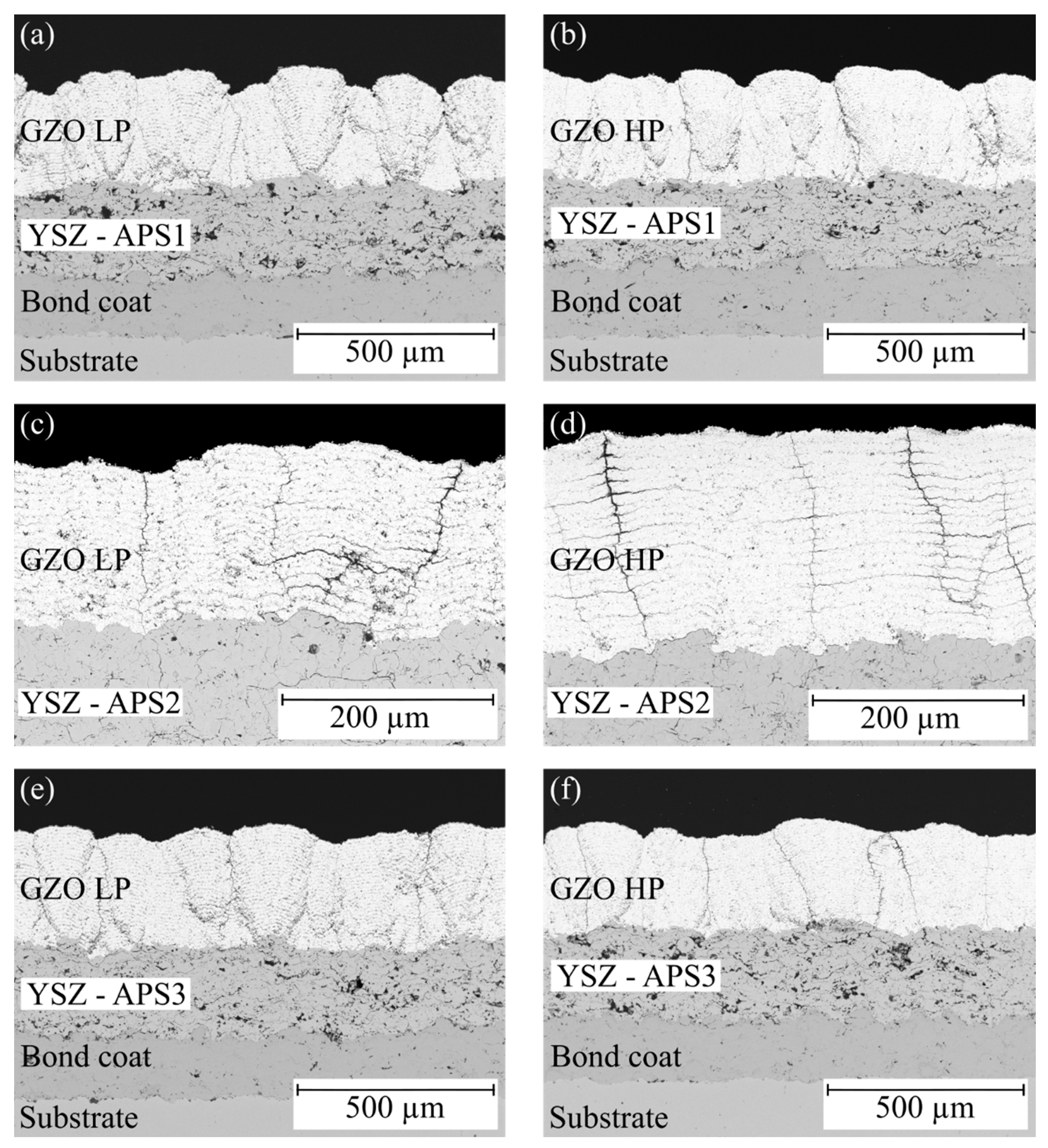
Figure 1. Cross-sections of different double-layer systems in the as-sprayed state: (a,b) with the standard APS coating, (c,d) with the APS coating with a smooth surface, and (e,f) with a rough APS surface coated with a GZO coating produced with a low-process gas flow in the left column and a high-process gas flow in the right column.
Coatings 14 01566 g001
Figure 2. Surface topography of the APS interlayers produced with (a) the standard parameter APS1, (b) increased power and reduced spray distance APS2, and (c) reduced power APS3.
Coatings 14 01566 g002
Figure 3. Lifetime of the reference system and the four different double-layer systems.
Coatings 14 01566 g003
Figure 4. SEM cross-sections of the four different double-layer systems on the left side and the corresponding photos of the samples after failure on the right side. (a) APS monolayer reference system, (b) System A, (c) System B, (d) System (C) and (e) System (D).
Coatings 14 01566 g004
Figure 5. SEM images of the bond with measuring points of EDX analysis (a) in the as-sprayed state and (b) in the cycled state.
Coatings 14 01566 g005
Figure 6. XRD diffractograms of the raw powder of the suspension, GZO layer sprayed with the GZO LP parameter, and two GZO LP samples after different thermal cycle times of 320 and 480 h: (a) Bragg angle from 10 to 80°, (b) zoomed on characteristic pyrochlore peak positions.
Coatings 14 01566 g006
Figure 7. High-magnification SEM images of (a) GZO LP as sprayed, (b) GZO LP after thermal cycling (~180 h), (c) APS1 as sprayed, (d) APS1 after thermal cycling (~180 h), and (e) APS1 monolayer after thermal cycling (~140 h); the cycling temperature is 1100 °C.
Coatings 14 01566 g007
Figure 8. Young’s modulus (left) and hardness (right) of APS, GZO LP, and GZO HP coatings in the as-sprayed state and after thermal cycling at 1100 °C.
Coatings 14 01566 g008
Table 1. Particle size distribution of the YSZ powder and GZO suspensions as well as further characteristics of the suspensions.
Particle Size Distribution [µm]ViscositySurface Tension
d90d50d1010−3 [Pa×s][mN/m]
Metco 204NS98.364.931.4--
GZO Batch 14.51.30.41.4 ± 0.0821.5
GZO Batch 25.31.70.31.4 ± 0.0821.7
Table 2. Chemical composition in wt.% of the YSZ powder according to the datasheet [41] and the GZO suspensions measured by Oerlikon Metco using ICP-.OE.
ZrO2Y2O3Gd2O3SiO2TiO2Al2O3Fe2O3Other OxidesPhases
Metco 204 NSBal. a7.0–8.0-<0.3<0.2<0.2<0.2<1.010% Monoclinic
GZO Batch 1Bal. b-58.14<0.01<0.01<0.020.01<0.04100% Cubic
GZO Batch 2Bal. c-58.37<0.01<0.010.040.01<0.04100% Cubic
a Maximum 2.5% HfO2 included in this value, b 0.89 HfO2 included in this value, c 0.86 HfO2 included in this value.
Table 3. Spray parameter of APS-YSZ interlayers.
Current
[A]
Argon
[nlpm]
Helium
[nlpm]
Standoff
[mm]
Robot Speed
[mm/s]
Meander
[mm]
Total Passes
APS142046420050029
APS2 a50046415050025 + 4
APS3 a38046420050028 + 4
a Parameter only used for the last four passes of the APS coating (before APS1).
Table 4. Spray parameter of SPS-GZO top layers.
Current
[A]
Argon
[nlpm]
Helium
[nlpm]
Standoff
[mm]
Robot Speed
[mm/s]
Meander
[mm]
GZO LP5004647010002
GZO HP4508087010002
Table 5. The parameter set for the production of the double-layered furnace cycle samples according to the images in Figure 1 and the achieved coating thicknesses.
Coating Thickness [µm]
Image in Figure 1System NameParameter UsedAPSGZO
(a)AAPS1 + GZO LP233.3 ± 17.5265.5 ± 19.1
(b)BAPS1 + GZO HP223.9 ± 19.2263.6 ± 22.8
(e)CAPS3 + GZO LP223.3 ± 20.9281.5 ± 11.4
(f)DAPS3 + GZO HP223.5 ± 20.6254.0 ± 16.2
Table 6. Chemical composition at EDX measuring points in Figure; spectra 1–7 are the as-sprayed samples.
AlCrCoNiY
Spectrum 172241300
Spectrum 272241300
Spectrum 3131834350
Spectrum 4121932361
Spectrum 5102137311
Spectrum 672241300
Spectrum 772241300
Mean values92138320.3
Map 192138320
Map 282138321
Spectrum c142233400
Spectrum c242232400
Spectrum c342233400
Spectrum c442233390
Spectrum c542233390
Disclaimer/Publisher’s Note: The statements, opinions and data contained in all publications are solely those of the individual author(s) and contributor(s) and not of MDPI and/or the editor(s). MDPI and/or the editor(s) disclaim responsibility for any injury to people or property resulting from any ideas, methods, instructions or products referred to in the content.