Article

Effects of Bias Voltages on the Tribological Behaviors of DLC Coatings

1
School of Mechanical and Automotive Engineering, Qingdao University of Technology, Qingdao 266520, China
2
Valve Intelligent Equipment Engineering Research Center, Department of Mechanical and Electrical Engineering, Hebei Vocational University of Technology and Engineering, Xingtai 054035, China
3
School of Mechanical Engineering, Ningxia University, Yinchuan 750021, China
4
Qingdao Choho Industrial Co., Ltd., Qingdao 266520, China
*
Author to whom correspondence should be addressed.
Coatings 2024, 14(2), 176; https://doi.org/10.3390/coatings14020176
Submission received: 31 December 2023 / Revised: 28 January 2024 / Accepted: 29 January 2024 / Published: 30 January 2024
(This article belongs to the Section Tribology)

Abstract

:
Ti/TiN/(Ti,N)-DLC/Ti-DLC/DLC coatings were deposited on 431 stainless steel using direct current magnetron sputtering technology under different bias voltages(0 V, −100 V, −200 V and −300 V). The microstructure and tribocorrosion performance of these DLC coatings in seawater was investigated. The results indicated that under the bias voltages, a denser and smoother surface of DLC coatings with a higher bonding strength between coatings and substrates was observed related to the increased incident kinetic energy of deposited ionized atoms. When the bias voltage was −200 V, the surface roughness reduced from 9.81 nm to 7.03 nm, and the bonding strength enhanced from 8.23 N to 8.86 N. What is more, the sp3 bond proportion and the disorder degree in DLC coatings both increased, which resulted in improved hardness and deformation resistance. However, when the bias voltage was −300 V, the increase of the amorphization was associated with a simultaneous rise in internal stress, which reduced the hardness and bond strength a little (8.72 N). DLC coatings can effectively improve the tribocorrosion properties of 431 stainless steel in seawater. When the voltage was −200 V, the average friction coefficient decreased from 0.35 to 0.07, with shallower wear traces and the wear loss of the DLC coating also being the smallest. The abrasive wear caused by metal oxides falling off the grinding ball, and the plastic deformation of the DLC coatings are the main wear forms. The high-density structure of DLC coatings under bias voltages can not only prevent the rapid expansion of cracks during deformation, but also provides a physical barrier to the erosion, which improves the corrosion and friction resistance in seawater. The optimization of bias voltage can improve the tribological performance of DLC coatings by regulating the carbon chain bond and microstructure. These results provide reference for DLC preparation and their potential engineering applications in stainless steel.

1. Introduction

Type 431 stainless steel is an engineering and decorative material combined with high hardness, high strength, and excellent corrosion resistance [1]. Components such as shafts, pumps, valves, bolts, nuts, washers, and other mechanical parts made of this material are widely employed in the mechanical industry [2,3]. However, with the continuous development of the equipment manufacturing industry, the service environment for stainless steel is becoming increasingly harsh, such as chemical, acidic, alkaline, and high-temperature environments. The failure of components caused by serious wear is a key factor influencing their service life. Surface engineering is essential for stainless steel to meet the performance requirements under different working conditions. The application of coatings is an effective method to improve surface morphology, corrosion performance, and mechanical properties [4].
Diamond-like carbon (DLC) coating represents an amorphous structure combined with sp2 and sp3 carbon bonds with a minimal presence of sp1 bonds [5]. Consequently, these coatings exhibit properties of graphite and diamond. The mechanical properties of the coating are predominantly determined by the portion of sp3 bonds, while the physical properties are primarily influenced by the sp2 bonds. These amorphous carbon coatings also have outstanding properties, including a low coefficient of friction, high hardness, and excellent wear resistance with potential application towards forming lubricant-free devices [6]. DLC are considered ideal coatings for diverse applications, including press joint components [7], combustion engine piston pins [8], high-speed steel tools [9], medical devices [10] and rubber seals [11]. However, the mismatch of thermal expansion coefficients and the elastic module between the metallic matrix and the DLC coatings, as well as the poor interfacial atomic affinity, results in high residual stress [4]. And the brittleness of DLC coatings also limits their thickness, adhesion, and load-bearing capability. The presence of various metallic elements in stainless steel has a catalytic effect during the DLC preparation, which results in the mass formation of graphite phase and decreases the hardness of DLC coatings [12]. It is also revealed that a dimple texture induces graphitization when DLC coating is deposited on steel, and wear rate would decrease significantly as the dimple density increases [4]. Element doping and transition layer structures are developed to improve the performance of DLC coatings. It is found that Ti [13], Cr [14], W [15] and Si [16,17] are carbide-forming elements that could form nano-carbide embedded in the DLC coatings to release the initial stress and improve the bonding strength. For example, Ti content of the Ti-DLC coatings was prepared to determine the microstructural characteristics, and it was found that at low Ti content (<2.8 at. %) some amorphous titanium carbide phase would form, and with the increase in Ti content, TiC nano-crystallite may form [18]. Shen [13] et al. have deposited Ti-doping DLC coatings onto 304L stainless steel and found that the doped Ti elements can relax the structure as pivot sites and decrease the residual stress. Y. Uzun [19] has deposited Ti-DLC coatings onto 316L stainless steel and found that the incorporation of Ti elements significantly enhances the bonding strength between the coating and the substrate. Cai [20] et al. have investigated the source current on Cr-doping DLC performance deposited on stainless steel and found that the hollow cathode ion source current can promote tribological properties due to the formation of chromium carbide. When the content of sp3 bond and the CrC phase in the coating increases, the hardness and the elastic modulus of DLC improve. Song [21] et al. have prepared W-DLC coatings and demonstrated that the formation of tungsten nano-carbide phases in the W-DLC coatings in the amorphous carbon matrix, constituting a composite nanocrystalline/amorphous structure facilitates stress release. And W doping has increased the interfacial bonding strength, with improved hardness and elastic modulus, which also enhances the tribological properties. However, too many carbolic grains in DLC reduces the coordination number of C atoms in the amorphous carbon matrix and leads to the increase in sp2 bonds and decreases the hardness of coatings. Zhao et al. [22] created Si-DLC coatings and found that as the Si content increases, the proportion of sp3/sp2 improves. Then, the hardness and the degree of disorder are both increased in Si/N-DLC coatings due to the co-operation of Si and N. The high electronegativity of N has a trend to form C-N bond in Si/N-DLC coatings, which makes the uneven distribution of C-C bonds and leads to a decrease in the order of structure. Zhang [23] et al. have investigated the effect of target currents on the Ti-DLC coatings and found coatings deposited at lower Ti target currents have a denser structure with the highest hardness. But too high target currents lead to more carbon ions with higher energy which increases the collision probability and reduces the energy before deposition and may produce ion aggregation, resulting in a decrease in surface quality and hardness.
In addition to doping elements, the transition layer has also been widely used to improve DLC properties. Dalibon [24] et al. have investigated the monolayer and multilayer Si-doped DLC coatings and found that multilayer coatings have better bond strength. The presence of multi-layer structures can reduce the crack propagation and the peeling phenomenon also improves the toughness of the coatings. Guo [25] et al. prepared (Cr,N)-DLC/DLC coatings and investigated the effect of intermediate layers on tribological properties. They found that (Cr, N)-DLC intermediate layers encompass the composite structures of amorphous carbon film phase containing a small amount of nanocrystalline chromium compounds. Although the content of nanocrystalline chromium is small, part of the internal stress of the coating is released, which improves the bonding strength between the substrate and the coating, and the performance of DLC coatings. The design of transition layers, optimizing coating deposition parameters, and multilayer structures may improve the performance of DLC coatings [26,27].
Although there have been methods proposed to reduce the internal stress of DLC coatings, the thickness and bonding strength of DLC coating still need to be further improved for wide applications. With the development of marine industry and deep-sea technology processes, tribocorrosion properties becomes an important performance factor. Therefore, in this paper, DLC coatings containing Ti/TiN/(Ti,N)-DLC/Ti-DLC/DLC mutilayers are deposited using the magnetron sputtering technique on 431 stainless steel, and the effects of bias voltage on their microstructure and tribocorrosion properties are investigated in seawater. This research holds significant value in elucidating the relationship between the structure and properties of DLC coatings.

2. Experiment Details

2.1. Preparation of DLC Coatings

DLC coatings are prepared on the surface of 431 stainless steel substrates using DC magnetron sputtering. The 431 stainless steel and silicon wafers are ultrasonically cleaned in anhydrous ethanol for 15 min before deposition and then dried in a dust-free cloth to remove surface grease and impurities to further improve the quality of DLC coatings. The targets are pure graphite and titanium (99.99 at. %), and the working gases are argon and nitrogen with 99.99% purity. Before deposition, the vacuum is drawn to 3 × 10⁻³ Pa and the cleaning glow is carried out at a high bias voltage of −800 V for 15 min. The transition layers are pure Ti, TiN, TiN-DLC and Ti-doping DLC are successively deposited on the substrate.
In the process of deposition, the temperature in the vacuum is maintained at 100 °C, and the continuous injection of Ar is 50 sccm. The current is 3A, the voltage is 300 V, and the targets are cooled by circulating water. The bias voltage is applied to the substrate and maintained during the total deposition process. Firstly, the Ti target is started and the first Ti transition layer is formed. Then, N2 (20 sccm) is injected to form the second transition layer of TiN. Subsequently, the C target starts to form the third transition layer of TiNC, and then the injection of N2 is turned off. Fourthly, the Ti-doped carbon layer is formed by continuous deposition, and then the Ti target is turned off. The deposition time of each transition layer is kept for 25 min. After those four transition layers are deposited, the individual graphite target begins to deposit the outer carbon film with the deposition time of 2 h. Both the transition layers and the outer DLC coatings are prepared under the same bias voltages. Different coatings are deposited at 0 V, −100 V, −200 V and −300 V. The deposition parameters are shown in Table 1. After the coatings’ deposition, they are cooled in the vacuum chamber to room temperature.

2.2. Characterization and Analysis Methods

The coatings’ structure is characterized using a high-resolution dispersive Raman spectrometer (Thermo Fischer DXR, Waltham, MA, USA). The Raman measurement is performed using 532 nm of the wavelength laser source, and the spectra in the range of 800 to 1800 cm−1 are recorded at room temperature. X-ray diffraction (XRD) analysis is performed for identifying phases that exist within the coatings (Bruker D8 Advance, Bremen, Germany). Using a continuous scanning mode, with copper Kα, and the diffraction angle ranges from 20° to 90° with the scanning speed of 5°/min. XRD data are analyzed by Jade6 software. The surface morphology and coating thickness (by the cross-sectional observation) are examined by the field emission scanning electron microscopy, SEM (MERLIN Compact, Forchtenberg, Germany). The atomic force microscopy, AFM (Bruker Nana, Goleta, CA, USA) in tapping mode is used to characterize the surface topography and the average roughness (Ra) of the DLC coatings with a square area of 5 × 5 µm, and the scan is carried on with sharp tips in dynamic mode. The hardness and elastic modulus of different coatings are measured by a nanoindenter instrument (Bruker Hysitron TI980, Bremen, Germany). The penetration depths of the indenter are set as about 300 nm. And the indentation depth is not exceeded to 1/10 of the total coating thickness to avoid the influence of the substrate. The plateau values in the range of 50–100 nm are selected as the hardness and elastic modulus. The measurements are produced at 5 random locations throughout the surface to ensure repeatability. The average value of these 5 points is taken as the experimental value of nanohardness and elastic modulus. The nano-indentation tests are also performed under a load of 5 N to evaluate the fracture toughness of the DLC coatings. The adhesion strength of the coatings is measured using a progressive load mode technique with a nano scratch tester (UNHT, Geneva, Switzerland). The test is performed with a scratch length of 3 mm and a gradual loading from 0 to 20 N. A continuous load with the speed of 5 N/min is carried out. Three scratch tests are performed on each coating to ensure the reliability of the experimental data. The scratch morphology of the coating is observed by an optical microscope, OM (DM1750M, Wetzlar, Germany), and the critical load is measured. The tribotest is carried out at room temperature using a reciprocating friction and wear tester (Bruker UMT-3, Goleta, CA, USA). The counter-grinding balls are made of GCr15 steel with a diameter of 9 mm. During the test, the load of 5N is applied at a stable frequency of 2 Hz for 30 min. The wear track of DLC coatings is observed by SEM. Then, the wear loss of the coatings is calculated by the Archard Equation (1) [28].
Q = K F D H
where Q is the wear rate (mm·N/Pa), K is the friction coefficient, F is the normal load (N), D is the wear sliding distance (mm), and H is the surface hardness of the coatings (Pa).

3. Results and Discussion

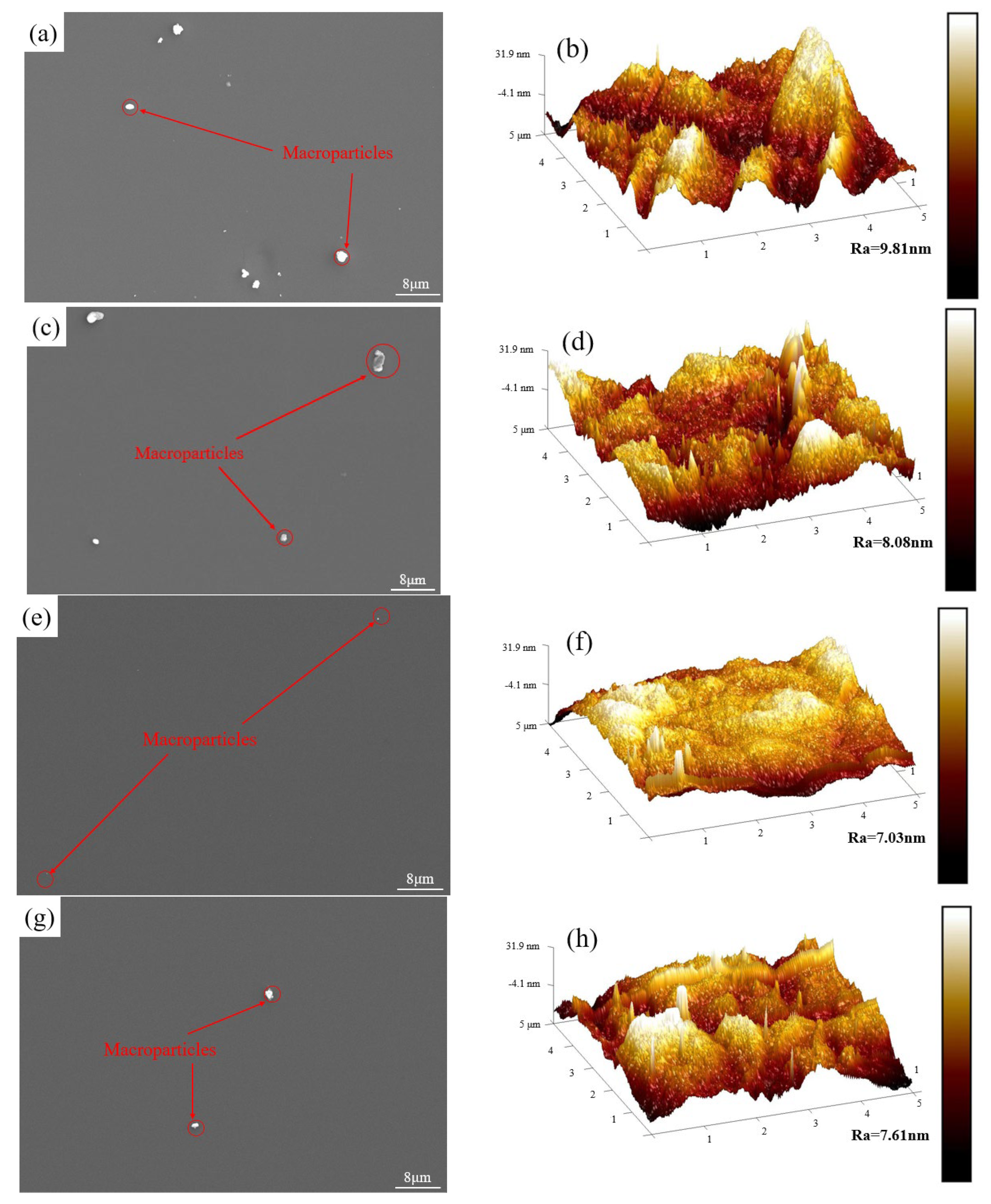
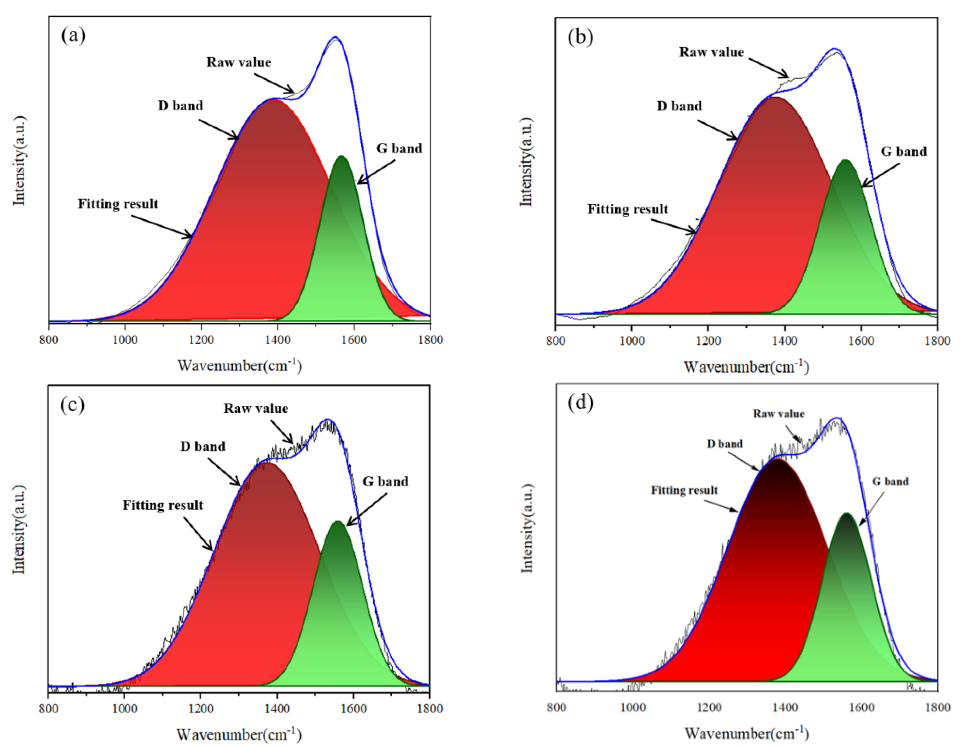
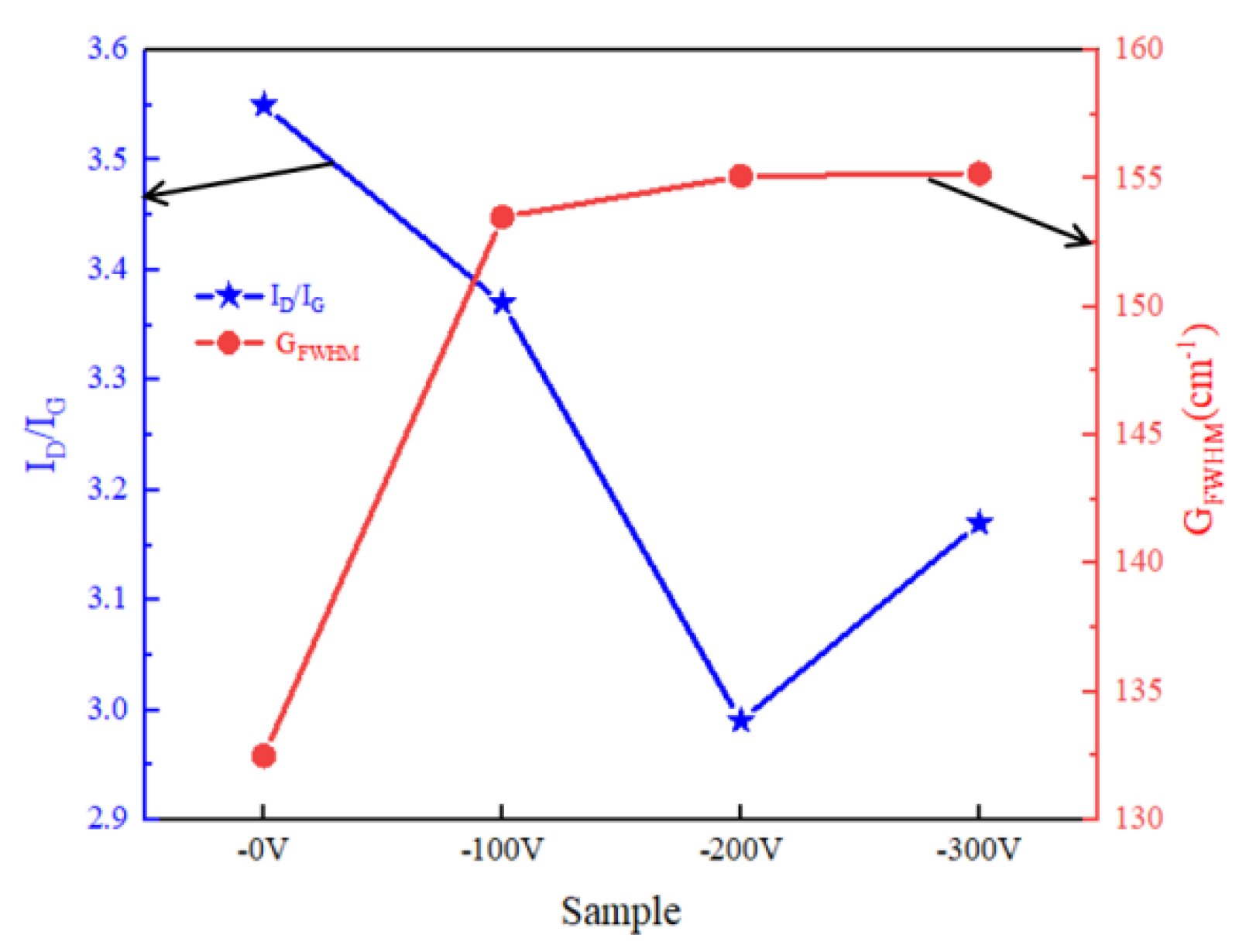
3.1. Morphological and Structure of DLC Coatings

Figure 1 shows the SEM and AFM surface morphology and the average roughness (Ra) of different coatings. The surface morphology shows that the surface is composed of small macroparticles, and their number and size decrease with bias voltage. What is more, the Ra values are 9.81 nm, 8.08 nm, 7.03 nm and 7.61 nm. The bias voltage can enhance the mobility of ionized atoms on the growing coating surface, which may reduce the magnitude of voids and particles, and make the coating surfaces much smoother [20]. Notably, the surfaces of coatings deposited at −200 V are the smoothest ones with fewer macroparticles. The roughness of DLC coatings is determined mainly by the atomic diffusion and argon ion-etching. Under low-bias voltage, the energy of the sputtered carbon atoms is insufficient for long atomic migration and penetrating depth. These carbon atoms with limited mobility energy would accumulate in the coating growing process contributing to the formation of clusters or macroparticles on the surface [29].
Figure 2 shows the cross-sectional morphology of DLC coatings under varying bias voltages. The total thickness is approximately 4 μm for coatings prepared at four bias voltages. And the thickness decreases slightly from 4.47 μm to 4.07 μm when the bias voltages increase to −300 V. The increased bias voltage increases the strength of the electric field between the substrate and the targets, then the ionized atoms are accelerated before deposition thus increasing their kinetic energy. At the same time, the ionization rate is also improved which facilitates the formation of strong carbon bonds in the coating structure. The intensified ions with high energy, significantly heighten the bombardment and the deposited ions are further compacted. Additionally, those deposited atoms with poor or not high enough adhesion strength may be washed away for the etching effect. Consequently, surface roughness is reduced and the structure is dense.
However, too high bias voltage results in excessive acceleration of ionized atoms, then the ion-etching rate and re-sputtering effect are both increased which would cause the separation of atoms from the growing coatings. The etched ions aggregate to form macroparticles under the action of surface energy. And the existence of etching can also lead to local defects and an uneven surface of the coating [30]. As a result, the surface roughness is further increased.
Figure 3 is the XRD pattern of DLC coatings prepared under the bias voltage of −200 V. There is a diffraction peak at 2θ = 43.9° which may correspond to the ferrites from the substrate. But there may also be a diamond phase contribution. Then the TiN phase and the graphite phase diffraction peaks are situated at 2θ = 64.2° and 2θ = 82.9°, respectively. Additionally, a diffraction peak may be related to the phase of TiCN is also observed at 2θ = 41.7°. The observed peaks correspond to the steel substrate, intermediate layers, nitrides, and carbides that possibly formed during Ti doping on the DLC surface or DLC nanoparticles. What is more, the appearance of the diffraction peak of the metal compound phase is related to the X-ray penetration which is strong enough to penetrate the surface of the carbon coatings.
Raman spectroscopy is an effective technique for the analysis of the detailed bonding structure of amorphous carbon coatings [31]. Figure 4 shows the Raman spectra of DLC coatings deposited under different deposition bias voltages. Two strong peaks at 1380 cm−1 (D band) and 1560 cm−1 (G band) or so are simulated from Gaussian distribution curves. Their G peaks are at 1567.4 cm−1, 1559.9 cm−1, 1561.3 cm−1 and 1560.7 cm−1. It is known that the broad skewed peak at 1560 cm−1 in Raman spectrum is a characteristic of DLC coatings, which is also described as the fingerprint of DLC coatings [32,33]. The G (graphite) and D (disorder) modes are dominated in the Raman spectra of the disordered carbon structure. The D peak is related to the breathing vibrations covering only the sp2 sites in rings but the G mode peak corresponds to the vibration of any sp2 sites in both rings and chains [31]. The sp2/sp3 is inferred via the intensity ratio of the D and G modes (ID/IG) based on Ferrari’s work [25]. The ID and IG is calculated by the areas of the D and G bands, respectively, reflecting the content of sp2 bonds in DLC coatings. The decrease of the ID/IG ratio indicates a gradual reduction of the sp2 bond in the amorphous carbon structure. Both the trend of ID/IG and the full width of the G peak at the half maximum value (GFWHM) are presented in Figure 5. The minimum of ID/IG appears at sample −200 V, indicating that DLC coatings prepared with a bias voltage of −200 V had the highest content of sp3 bonds.
It is known that the G peak shifting to a lower wave number, and the GFWHM gradually broadening, is also associated with the decrease of sp2/sp3 [30]. When there is no bias voltage, the ID/IG ratio is 3.55 and GFWHM is 132.5 cm−1 with the G peak located at 1567.4 cm−1. When the bias voltage increases to −200 V, the ID/IG ratio decreases to 2.99 and the GFWHM shifts to 152.6 cm−1, indicating that there is a higher proportion of sp3-C bonds in the DLC coating structure. A G peak shift to 1561.3 cm−1 means that the disorder degree is also increased in DLC coatings. Based on the above analysis, the decrease of ID/IG with the increase of GFWHM means that the DLC coatings prepared under a bias voltage of −200 V have a more disordered structure with a higher fraction of sp3 bonds. This phenomenon can be explained through the subsurface injection model of coatings’ growth mechanism [30]. The increase of bias voltage provides sufficient energy to incident ions, enabling them to penetrate the outer atomic layer of the growing coatings. This penetration disrupts the net structure of sp2 bonds, leading to the formation of sp3 bonds. As it is known that when carbon ions have high enough kinetic energy and penetrating ability, sp2 bonds would transform to sp3 bonds [34]. Also, the amorphization is also strengthened for the coating forming process under the higher bias voltages, which would lead to higher disorder. Meanwhile, that amount of graphite-like structure may result in a macroparticle structure on the coating surface due to the high surface energy.

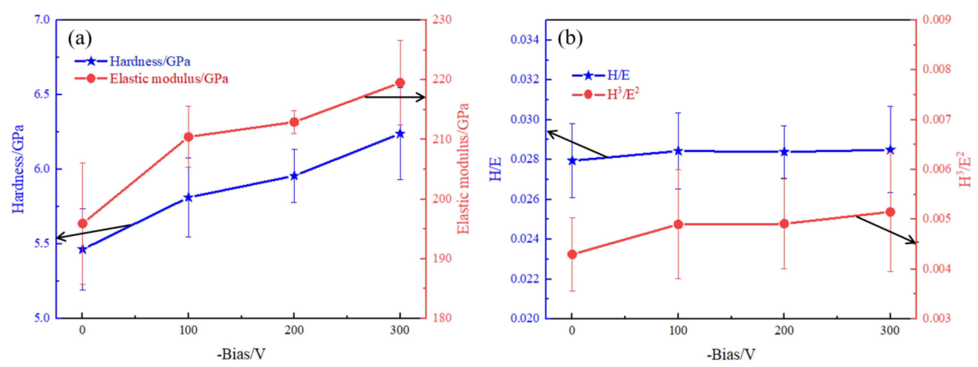
3.2. Mechanical Properties of DLC Coatings

Figure 6a shows the nano-hardness and elastic modulus of DLC coatings. The hardness of the 431 stainless steel is measured to be 1.91 GPa. The hardness of DLC coatings increases from 5.46 GPa to 6.25 GPa and the elastic modulus also rises from 195.26 GPa to 219.53 GPa when the bias voltage changes to −300 V which corresponds to the decrease of sp3 bonds in the structure and the increase of disorder degree under the bias voltages, as analyzed above. Figure 6b presents the H/E and H3/E2 ratios of DLC coatings, which describe the elastic strain to failure capability and the resistance to plastic deformation, respectively [29]. It can be observed that both H/E and H3/E2 ratios increase revealing that the ability of preventing crack formation and propagation is improved when there are bias voltages in the coating’s deposition process. The changing trend of GFWHM is much closer to that of hardness and elastic modulus. This indicates that the disorder of the DLC structure affects the coating’s mechanical properties. Disorder generates limited local distortion in the microstructure and enhances the ability to resist deformation, which improves coating hardness and elastic modulus [30].
It is noteworthy that the sample prepared under the bias of −300 V shows a slight reduction in sp3 content, but the hardness appears to be stable. Despite the slight decrease in sp3 bond content, the number and the size of macroparticles on the surface of DLC coatings have shown an apparent increase. In the test process, the indenter may contact with these macroparticles, and this will lead to an improvement in average hardness. Furthermore, the increased disorder of the sp2 bond also causes the high initial stress, which leads to the improved deformation resistance and higher hardness. The above experimental result proves that the existence of bias changes the structure of DLC coatings by influencing the sp2 bond and disorder and results in the changing mechanical performance.
The scratch test can analyze the bonding strength of the coatings. The load associated with peeling or delamination is called the critical load (LC). Among them, LC1 and LC2 are the critical loads corresponding to the occurrence of first cracking and successive peeling, respectively. Figure 7 shows the scratch track images and information of the DLC coatings deposited under different bias voltages. These four coatings have typical scratch trajectories with a large number of cracks and spalling damage with increasing normal load. It is generally believed that LC2 is the bond strength of the coatings and the substrate. The LC2 of these four coatings are 8.23 N, 8.42 N, 8.86 N and 8.72 N, indicating that supplying bias voltages during the preparation process has enhanced the bond strength and load-bearing capacity of the top DLC coatings. There is no obvious layer-by-layer rupture observed in the scratch morphology, which means that there is a good bond between transition layers. What is more, as the load steadily increases, the cracking of the scratched edge is weakened indicating the better plastic deformation capacity of these DLC coatings. Nevertheless, when the bias voltage reaches −300 V, the adhesion strength declines slightly. The light cracks are observed at the scratch edges with bright spots emerging in the substrate, revealing the crack propagation and a certain brittleness of the coatings, which may be due to the increase of disorder degree and the initial stress in these DLC coatings.
Figure 8 shows the coefficient of friction (COF) DLC coatings in seawater. There are fluctuations in COF of the substrate which is primarily attributed to the hydrophilicity of the stainless steel material. This property facilitates the formation of a water film between the substrate and the grinding ball. The presence of Cl−1 in seawater would destroy this film, leading to the formation of corrosion pits and accumulation of loose corrosion products. The variation of hardness of surfaces contacted with the grinding ball yields the fluctuation of COF. The graphite phases in DLC coatings are good solid lubrications and can reduce the COF. As a result, the average COF of the substrate is 0.35, but after depositing DLC coatings, it decreases, as shown in Figure 8b. The lowest value of 0.07 is observed when DLC coatings are prepared at −200 V. This reveals that the existence of DLC coatings can decreases the COF and the bias voltage also has influence on the tribological properties. Meanwhile, COF of DLC coatings prepared without bias voltage or with a bias voltage of −100 V exhibit fluctuation and temporal instability. As aforementioned, the DLC coatings prepared under lower bias voltages have relatively higher surface roughness and more randomly distributed macroparticles, which decreases the effective contact area between the grinding ball and the DLC coatings, and leads to an extended running-in period and fluctuating COF during the wear process. However, when the bias voltage increases to −200 V or −300 V, the sample exhibits a lower and more stable COF, which may be due to the dense and smooth surface with a higher hardness.
The wear loss analysis is shown in Figure 9, and it can be found that the wear resistance of 431 stainless steel is significantly improved after the deposition of DLC coatings. Type 431 stainless steel has the highest wear rate of 5.49 × 10⁻⁹ mmN/Pa. The DLC prepared at −200 V has a wear loss of 3.64 × 10⁻¹⁰ mmN/Pa, which is the lowest one showing better wear resistance. Moreover, the wear loss decreases with the bias voltage, which is related to the change of hardness and COF of coatings as discussed above. The amorphous structure of DLC coatings can effectively increases the resistance of crack propagation, and the denser structure further hinders the development of deformation. But when the bias voltage is −300 V, macroparticles shedding on the DLC surfaces increase friction and act as abrasives to create a relatively serious wear.
The wear track morphology of DLC coatings in seawater is shown in Figure 10. The labeled positions 1–8 represent the locations of EDS scanning tests, shown in Figure 11. It can be observed from Figure 10 that the width of the wear track decreases from 253.3 μm to 146.6 μm, correlated with the increase of hardness of the DLC coatings. With increasing reciprocating cycles during the 30-min sliding wear process, the most severe wear damage is observed in the non-biased voltage coatings. In addition, the presence of debris, grooves, and scratches are all presented in the wear track. Seawater may enter inner coatings through the pores or cracks, which makes coatings peel off during the sliding process. The surface is also scratched by debris from the grinding balls during the prolonged wear process. These results show that the abrasive wear and the plastic deformation are the main wear mechanisms.
Figure 11a shows the EDS results of points labeled 2 in Figure 10a. The increased Fe, Cr and O elements are presented on the wear track indicating the shedding off and formation of metal oxides on the grinding ball in seawater. The significant increase of carbon elements along the wear track and the stable COF throughout the experiment, confirms that DLC coatings are not peeling off in the wear process. When the bias voltage is −300 V, though the width of the wear track is 146.6 μm, there is no obvious debris on the surface. But small corrosive pits can be observed, as shown in Figure 10d, indicating that the corrosion wear and oxidation wear appear.
The presence of macroparticles on the surface of the coatings contributes to the fluctuations of friction in the beginning of the friction process in seawater. With the friction process going on, it is easy for seawater to enter the inner transition layers through gaps and vacancies in the coating structures, which accelerates the internal corrosion of the coating and even causes the partial peeling off of coatings from the substrate. Then the dense structure can delay the corrosion rate. Meanwhile, metal oxides, and hydroxides are formed in the worn surfaces under the chemical action of seawater and friction stress. As aforementioned, the structure of coatings deposited under higher bias voltages are much denser and the surface defects are reduced with high amorphization. The dense and compacted structure can not only reduce the defects but can also hinder the rapid development of corrosion by preventing seawater penetration. And the disordered microstructure reduces the number of grain boundaries and also increases friction crack propagation and deformation development barriers which further increases tribocorrosion performance. Therefore, the wear loss of the coatings prepared at the bias voltage of −200 V is relatively small, showing excellent tribocorrosion resistance. Combined with changes in the coefficient of friction, the result further indicates that the bias voltage during the DLC coating preparation further affects the tribological properties by influencing the microstructure of the DLC coatings.

4. Conclusions

The effects of supplying bias voltage to the substrate on the microstructure and tribological properties of the DLC coatings containing titanium transition layers were investigated. Although the existence of bias voltage has a weak influence on the overall thickness of DLC, it has a profound effect on the microstructure and mechanical properties of coatings. When the bias voltage increases from 0 V to −200 V, the magnitude of the gathered carbon macroparticles on the coating surface decreases. The bonding strength of DLC coatings also increases from 8.23 N to 8.86 N with decreased roughness. And the sp3-C bond content and disorder degree in DCL coatings are both enhanced inducing the improved hardness and deformation resistance. As bias further increases to −300 V, the etching effect is non-negligible which makes the accumulation of carbon ions and the improvement of surface roughness. During the friction experiment, though there is abrasive wear caused by oxides and debris shedding off the grinding ball, DLC coatings are not worn off which effectively protects the substrate and improves the tribocorrosion resistance of 431 stainless steels in seawater. Also, the friction coefficient could be reduced to 1/5 and the wear loss decline to 1/15 by supplying DLC coatings prepared at −200V, indicating the potential engineering applications. The bias voltage stimulates the amorphization in DLC coatings which increase the seawater corrosion resistance and normal stress deformation. These results prove that the optimization of bias voltage can improve the comprehensive tribological properties of DLC coatings by regulating the carbon bonds and the microstructure.

Author Contributions

Investigation, X.Y.; Resources, S.S., S.W., F.G., B.Z. and L.D.; Data curation, T.H.; Writing—original draft, S.Z. All authors have read and agreed to the published version of the manuscript.

Funding

This research was funded by the Natural Science Foundation of China (Grant No. 51861031).

Institutional Review Board Statement

Not applicable.

Informed Consent Statement

Not applicable.

Data Availability Statement

The data from this study are available from the corresponding author upon reasonable request.

Conflicts of Interest

Author Longjie Dai was employed by the company Qingdao Choho Industrial Co. The remaining authors declare that the research was conducted in the absence of any commercial or financial relationships that could be construed as a potential conflict of interest.

References

  1. Liu, Y.; Li, A.; Cheng, X.; Zhang, S.Q.; Wang, H.M. Effects of heat treatment on microstructure and tensile properties of laser melting deposited AISI 431 martensitic stainless steel. Mater. Sci. Eng. A Struct. 2016, 666, 27–33. [Google Scholar] [CrossRef]
  2. Hemmati, I.; Ocelík, V.; De Hosson, J.T.M. The effect of cladding speed on phase constitution and properties of AISI 431 stainless steel laser deposited coatings. Surf. Coat. Technol. 2011, 205, 5235–5239. [Google Scholar] [CrossRef]
  3. Khorram, A.; Jamaloei, A.D.; Jafari, A.; Moradi, M. Nd:YAG laser surface hardening of AISI 431 stainless steel; mechanical and metallurgical investigation. Opt. Laser Technol. 2019, 119, 105617. [Google Scholar] [CrossRef]
  4. Tyagi, A.; Walia, R.S.; Murtaza, Q.; Pandey, S.M.; Tyagi, P.K.; Bajaj, B. A critical review of diamond like carbon coating for wear resistance applications. Int. J. Refract. Met. Hard Mater. 2019, 78, 107–122. [Google Scholar] [CrossRef]
  5. Deng, Q.Y.; Wang, C.M.; Zhang, T.F.; Yang, W.M.; Li, X.Y.; Huang, N.; Leng, Y.X. Regulating the uniformity of DLC films in ECR plasma with negative substrate biasing. Surf. Coat. Technol. 2019, 365, 15–23. [Google Scholar] [CrossRef]
  6. Mosayebi, M.J.; Hosseini, S.R. Structural and tribological properties of TiC-DLC coatings deposited by RCAE-PVD at various bias voltages. Surf. Eng. 2015, 31, 96–102. [Google Scholar] [CrossRef]
  7. Kowalski, S. Influence of diamond-like carbon coatings on the wear of the press joint components. Wear 2021, 486, 204076. [Google Scholar] [CrossRef]
  8. Kowalski, S.; Cieslikowski, B.; Barta, D.; Dizo, J.; Dittrich, A. Analysis of the Operational Wear of the Combustion Engine Piston Pin. Lubricants 2023, 11, 100. [Google Scholar] [CrossRef]
  9. Talibouya, B.E.C.; Sérgio, M.P.; Eduardo, D.S.C.; Andrade, M.L.H.; Wanderson, B.J.; Rosa, D.M. Study of the behavior of skewness (Rsk) and kurtosis (Rku) parameters in the dry drilling process of Al-Mg-Si alloy 6351 T6 using a Diamond-Like Carbon coated high-speed steel tool. Tribol. Int. 2024, 191, 109149. [Google Scholar]
  10. Kaneko, M.; Hiratsuka, M.; Alanazi, A.; Nakamori, H.; Namiki, K.; Hirakuri, K. Surface Reformation of Medical Devices with DLC Coating. Materials 2021, 14, 376. [Google Scholar] [CrossRef]
  11. Pei, Y.T.; Bui, X.L.; Zhou, X.B.; De Hosson, J.T.M. Tribological behavior of W-DLC coated rubber seals. Surf. Coat. Technol. 2008, 202, 1869–1875. [Google Scholar] [CrossRef]
  12. Borges, C.F.M.; Pfender, E.; Heberlein, J. Influence of nitrided and carbonitrided interlayers on enhanced nucleation of diamond on stainless steel 304. Diam. Relat. Mater. 2001, 10, 1983–1990. [Google Scholar] [CrossRef]
  13. Shen, Y.Q.; Luo, J.; Liao, B.; Zhang, X.; Zhao, Y.Y.; Zeng, X.M.; Chen, L.; Pang, P.; Bao, F. Tribocorrosion and tribological behavior of Ti-DLC coatings deposited by filtered cathodic vacuum arc. Diam. Relat. Mater. 2022, 125, 108985. [Google Scholar] [CrossRef]
  14. Zhong, W.; Wang, H.Y.; Ma, L.; Zhang, C.H. Impact Abrasive Wear of Cr/W-DLC/DLC Multilayer Films at Various Temperatures. Metals 2022, 12, 1981. [Google Scholar] [CrossRef]
  15. Li, D.S.; Kong, N.; Li, R.S.; Zhang, B.Y.; Zhang, Y.S.; Wu, Z.G.; Zhang, Q.D. The tribological performance of W-DLC in solid-liquid lubrication system addivated with Cu nanoparticles. Surf. Topogr. Metrol. Prop. 2021, 9, 045043. [Google Scholar] [CrossRef]
  16. Gao, M.; Kim, S.B.; Li, Y.H.; Ramaswamy, S.H.; Choi, J. Triboelectric nanogenerator with enhanced output and durability based on Si-DLC films. Nano Energy 2023, 105, 107997. [Google Scholar] [CrossRef]
  17. Shang, L.L.; Gou, C.X.; Li, W.S.; He, D.Q.; Wang, S.H. Effect of microstructure and mechanical properties on the tribological and electrochemical performances of Si/DLC films under HCl corrosive environment. Diam. Relat. Mater. 2021, 116, 108385. [Google Scholar] [CrossRef]
  18. Jo, Y.J.; Zhang, T.F.; Son, M.J.; Kim, K.H. Synthesis and electrochemical properties of Ti-doped DLC films by a hybrid PVD/PECVD process. Appl. Surf. Sci. 2018, 433, 1184–1191. [Google Scholar] [CrossRef]
  19. Uzun, Y. Tribocorrosion properties of plasma nitrided, Ti-DLC coated and duplex surface treated AISI 316L stainless steel. Surf. Coat. Technol. 2022, 441, 128587. [Google Scholar] [CrossRef]
  20. Cai, Y.; Liu, H.D.; Ma, Y.; Wan, Q.; Chen, H.; Liu, Y.; Chen, Y.M.; Mei, Q.S.; Yang, B. Effect of Ion Source Current on the Microstructure and Properties of Cr-DLC Coatings Prepared by Ion Beam-Assisted Arc Ion Plating. NANO 2017, 12, 1750053. [Google Scholar] [CrossRef]
  21. Song, R.W.; Chen, S.; Liu, Z.W.; Huo, C.Q.; Chen, Q. Effect of W-doping on the structure and properties of DLC films prepared by combining physical and chemical vapor deposition. Diam. Relat. Mater. 2023, 132, 109687. [Google Scholar] [CrossRef]
  22. Zhao, Q.P.; Kang, S.M.; Zou, F.Z.; Huo, Z.K. Structure and properties of Si and N co-doping on DLC film corrosion resistance. Ceram. Int. 2023, 49, 2121–2129. [Google Scholar] [CrossRef]
  23. Zhang, S.D.; Yan, M.F.; Yang, Y.; Zhang, Y.X.; Yan, F.Y.; Li, H.T. Excellent mechanical, tribological and anti-corrosive performance of novel Ti-DLC nanocomposite thin films prepared via magnetron sputtering method. Carbon 2019, 151, 136–147. [Google Scholar] [CrossRef]
  24. Dalibon, E.L.; Moreira, R.D.; Guitar, M.A.; Trava-Airoldi, V.J.; Bruhl, S.P. Influence of the substrate pre-treatment on the mechanical and corrosion response of multilayer DLC coatings. Diam. Relat. Mater. 2021, 118, 108507. [Google Scholar] [CrossRef]
  25. Guo, C.Q.; Pei, Z.L.; Fan, D.; Gong, J.; Sun, C. Microstructure and tribomechanical properties of (Cr, N)-DLC/DLC multilayer films deposited by a combination of filtered and direct cathodic vacuum arcs. Diam. Relat. Mater. 2015, 60, 66–74. [Google Scholar] [CrossRef]
  26. Lara, L.C.; Costa, H.; de Mello, J.D.B. Influence of layer thickness on sliding wear of multifunctional tribological coatings. Ind. Lubr. Tribol. 2015, 67, 460–467. [Google Scholar] [CrossRef]
  27. Radi, P.A.; Vieira, A.; Manfroi, L.; Nass, K.C.D.; Ramos, M.A.R.; Leite, P.; Martins, G.V.; Jofre, J.B.F.; Vieira, L. Tribocorrosion and corrosion behavior of stainless steel coated with DLC films in ethanol with different concentrations of water. Ceram. Int. 2019, 45, 9686–9693. [Google Scholar] [CrossRef]
  28. Mazaheri, Y.; Jalilvand, M.M.; Heidarpour, A.; Jahani, A.R. Tribological behavior of AZ31/ZrO2 surface nanocomposites developed by friction stir processing. Tribol. Int. 2020, 143, 106062. [Google Scholar] [CrossRef]
  29. Guo, C.Q.; Li, H.Q.; Peng, Y.L.; Dai, M.J.; Lin, S.S.; Shi, Q.; Wei, C.B. Residual stress and tribological behavior of hydrogen-free Al-DLC films prepared by HiPIMS under different bias voltages. Surf. Coat. Technol. 2022, 445, 128713. [Google Scholar] [CrossRef]
  30. Wang, L.J.; Liu, Y.; Chen, H.; Wang, M.C. Nanoindentation-induced deformation behaviors of tetrahedral amorphous carbon film deposited by cathodic vacuum arc with different substrate bias voltages. Appl. Surf. Sci. 2022, 576, 151741. [Google Scholar] [CrossRef]
  31. Chu, P.K.; Li, L. Characterization of amorphous and nanocrystalline carbon films. Mater. Chem. Phys. 2006, 96, 253–277. [Google Scholar] [CrossRef]
  32. Yoon, S.F.; Yang, H.; Rusli, A.; Ahn, J.; Zhang, Q. The effects of self-generated DC bias on the characteristics of diamond-like carbon films prepared using ECR-CVD. Diam. Relat. Mater. 1998, 7, 70–76. [Google Scholar] [CrossRef]
  33. Qi, J.W.; Wang, L.P.; Yan, F.Y.; Xue, Q.J. The tribological performance of DLC-based coating under the solid-liquid lubrication system with sand-dust particles. Wear 2013, 297, 972–985. [Google Scholar] [CrossRef]
  34. Lifshitz, Y.; Lempert, G.D.; Grossman, E. Substantiation of subplantation model for diamondlike film growth by atomic force microscopy. Phys. Rev. Lett. 1994, 72, 2753–2756. [Google Scholar] [CrossRef]
Figure 1. Surface morphology of DLC coatings: (a,b) 0 V; (c,d) −100 V; (e,f) −200 V; (g,h) −300 V.
Coatings 14 00176 g001
Figure 2. Cross-section of DLC coatings prepared under different bias voltages: (a) 0 V; (b) −100 V; (c) −200 V; (d) −300 V.
Coatings 14 00176 g002
Figure 3. XRD pattern of DLC coatings.
Coatings 14 00176 g003
Figure 4. Raman spectra of DLC coatings prepared under different bias voltages: (a) 0 V; (b) −100 V; (c) −200 V; (d) −300 V.
Coatings 14 00176 g004
Figure 5. ID/IG ratio and GFWHM value of DLC coatings prepared by different bias voltages.
Coatings 14 00176 g005
Figure 6. Hardness and elastic modulus of DLC coatings: (a) Hardness and elastic modulus (b) H/E and H3/E2 values.
Coatings 14 00176 g006
Figure 7. Scratch morphology and bond strength of DLC coatings: (a) 0 V (b) −100 V (c) −200 V (d) −300 V.
Coatings 14 00176 g007
Figure 8. Friction coefficient curves and average values of DLC coatings: (a) Friction coefficient curves (b) Average values.
Coatings 14 00176 g008
Figure 9. Wear loss of DLC coatings and the substrate.
Coatings 14 00176 g009
Figure 10. Wear trace of DLC coatings prepared by different bias voltages: (a) 0 V (b) −100 V (c) −200 V (d) −300 V.
Coatings 14 00176 g010
Figure 11. EDS spectra of DLC coatings: (a) 0 V (b) −100 V (c) −200 V (d) −300 V.
Coatings 14 00176 g011
Table 1. Deposition parameters of DLC coatings.
ParametersTargets and GasTemperature/°CDepositing Time/minBias Voltage/V
Layer TiCArN2
Tionoffonoff100250 V/−100 V/−200 V/−300 V
TiNonoffonon100250 V/−100 V/−200 V/−300 V
(Ti,N)-DLConononon100250 V/−100 V/−200 V/−300 V
Ti-DLConononoff100250 V/−100 V/−200 V/−300 V
DLCoffononoff1001200 V/−100 V/−200 V/−300 V
Disclaimer/Publisher’s Note: The statements, opinions and data contained in all publications are solely those of the individual author(s) and contributor(s) and not of MDPI and/or the editor(s). MDPI and/or the editor(s) disclaim responsibility for any injury to people or property resulting from any ideas, methods, instructions or products referred to in the content.

