Article

Preparation of NaCl Particles Added Polyvinylidene Fluoride Microporous Filter and a Simple Filtration Device

1
College of Electron and Information Engineering, University of Electronic Science and Technology of China Zhongshan Institute, Zhongshan 528402, China
2
School of Physics, University of Electronic Science and Technology of China, Chengdu 610054, China
*
Author to whom correspondence should be addressed.
Coatings 2024, 14(2), 196; https://doi.org/10.3390/coatings14020196
Submission received: 22 December 2023 / Revised: 24 January 2024 / Accepted: 31 January 2024 / Published: 2 February 2024

Abstract

:
Clean and pollution-free water plays a crucial role in human metabolism and is essential for everyone’s daily life. However, with industrialization, a significant amount of sewage has been produced for many years. Water resources tend to become stressed when the rate of sewage production speed is purified. Many researchers are working on sewage purification to eliminate this hidden danger. It is urgent to find an efficient, high-speed, and environmental way to purify sewage. The objective of this study is to investigate the impact of pore morphology on filtration. In addition, a Polyvinylidene fluoride (PVDF)-microporous filter (MPF) based on non-solvent-induced phase separation (NIPS) and vapor-induced phase separation (VIPS) methods was designed, the morphology and properties of a series of sodium chloride particles (NaCl-ps) added PVDF-MPF was researched, and a simple semi-automatic filtration device based on the character of this PVDF-MPF was manufactured. According to the light transmittance of filtered sewage through PVDF-MPF and NaCl-ps added PVDF-MPF, both PVDF-MPFs can remove particles in sewage. However, after adding NaCl-ps, the purification capacity of PVDF-MPF is higher than that of PVDF-MPF without adding NaCl-ps. The addition of NaCl-ps changes the morphology and improves the sewage purification capacity of PVDF-MPF.

1. Introduction

The water filter, which can purify water, has been researched for many years since its initial development [1,2,3]. The Ground is the most massive and longest existing filter among filters and a typical filtration device in the natural environment [4]. Stones, sands, and soils in the ground form many voids [5], pore structures [6], and capillary textures [7]. Surface sewage becomes cleaner as it passes through these structures on the ground. Inspired by this phenomenon, many researchers have studied sewage purification [8,9]. The pore size of a filter is a crucial factor for sewage purification. The appropriate aperture can effectively remove the impurities of the corresponding particle size. In addition, the filtration process can be viewed as a classification process [10]. Figuring out the main difference between pure water and sewage is the key point. Sewage usually contains water, dust, soil, mud, bacteria, metal salts, and other chemical reagents. On the contrary, pure water only covers water. Most of the impurities in sewage are larger than water molecules. Therefore, substances in sewage can be sorted through filters to remove impurity particles. The filter is a sorting device mainly composed of pores and corresponding supporting structures [11]. According to pore size, filters can be divided into microfiltration filets [12,13], nanofiltration filets [14,15], and ultrafiltration filets [16].
A pore is a space filled with air, and there are two ways to create pores: the addition method and the subtraction method. The addition method, in other words, is to pile up polymers or other materials sparsely, allowing them to occupy what would otherwise be air and leaving some space for pores to form. Filters with 80% porosity can be manufactured using an interesting and innovative cross-stacking method of polymer fibers [17,18,19]. It is representative of the add method [17,18]. Metal nanowires have similar properties to polymer fiber and may, therefore, have the ability to prepare filters [20,21,22]. Particle stacking is a traditional add method [23]. It mainly regulates the size and distribution of pores indirectly by controlling the size and position of the constituent particles. The subtraction method is in contrast to the addition method. It is based on the method of reducing part of the material. The use of defects formed during the fabrication of materials such as polymers [24,25] is an important means. Defects, usually owning a continuous or repeat structure, are related to the phases they present, including solid, liquid, and gas phases. The liquid and gas phases are repeated and continuous, while the solid phase is repeated but discontinuous. When these defects are removed, a filter with pores is left. Ariono and co-workers found that a high concentration of polymer wrapped the solvent to form a forms gel [26]. This is a typical liquid phase defect in the filter manufacturing process. There are usually three ways: Non-solvent-induced phase separation (NIPS) [27], vapor-induced phase separation (VIPS) [28], and temperature-induced phase separation to induce the polymer to form defects [29]. All of them comply with the law that a pore is occupied by other materials. The characteristics of the defective materials directly affect pore size and distribution density [30] because removing defective materials directly leaves holes. The addition of inorganic solid particles (like metal nanoparticles [31], graphene [32], and carbon nanotubes [33]) has been studied extensively. Gethard and co-workers reported that carbon tubes led to a 1.8 times flux increase and showed that the addition of carbon tubes might provide a pathway to mass transport [34]. Sharma and co-workers reported PEG could improve the porosity of cellulose acetate membranes [35]. This PEG material not only forms pores but also reduces polymer contraction, which means a more loosened and porous structure to improve the filtration. There are also some excellent papers that add removable particles to make novel filters [36,37].
The method of pore surface modification has also attracted researchers to pursue better filtering performance. The surface of the modified pore acts like a hand that can grab a kind of particular contamination or easily push water through the filter [3,38]. In other words, the pore surface modification changes its hydrophobicity and affinity for certain substances. The main principle is to increase the surface tension between water and the filter or to improve the interaction between certain impurities and the filter [39]. Wu developed a polystyrene-grafted cellulose-acetate membrane in 1992 [40]. Polyamide was coated with hydrophobic styrene butadiene rubber [41]. Sulfonated N, N-diethyl ethylenediamine deposited on polyvinylidene fluoride (PVDF) enhances the hydrophilic property [42].
In this paper, a porous PVDF filter was prepared by adding different weights of sodium chloride particles (NaCl-ps) into the solution containing N, N-Dimethylformamide (DMF), acetone, and PVDF by subtraction, NIPS, and VIPS methods. The experiment includes water vapor intrusion, solvent evaporation, and NaCl-ps removal. DMF and acetone are polar solvents that selectively and evenly dissolve PVDF but not NaCl-ps. The PVDF polymer forms the main skeleton of the filter [43], and sodium chloride (NaCl) is a solid particle that causes the pore defects of the filter. Meanwhile, NaCl is a non-toxic and inexpensive kind of halogen metal salt, which is an excellent additive in the process of making filters. The effects of different concentrations of NaCl-ps on the structure and properties of PVDF microporous filters (MPF) were studied. The morphology of PVDF-MPF was observed by scanning electron microscopy (SEM). Carbon ink filtration experiments show that PVDF-MPF has the ability to filter this sewage and may have the same effect on other sewage.

2. Experimental

2.1. Materials

PVDF was purchased from Arkema Inc., White Pigeons, France (Kynar 721, particles) with a mass density of 1.77–1.80 g·cm−3. DMF (analytical reagent) without any purification and absolute ethanol (analytical reagent) was supplied by Aladdin Reagent (Shanghai) Co., Ltd., Shanghai, China. Acetone (Tianjin Damao Chemical Reagent Co., Ltd., Tianjin, China) and NaCl was bought from local suppliers. Carbon ink was bought from Shanghai Hero Ink Factory (Shanghai, China). Deionized water was obtained from our laboratory. The scanning electron microscope (SEM) (TESCAN Brno, Co., Ltd., Brno, Czech Republic) images are taken. The transmittance is measured by the film transmissometer GZ502A (Shanghai, China) produced by Shanghai Guangzhao Photoelectric Technology Co., Ltd.

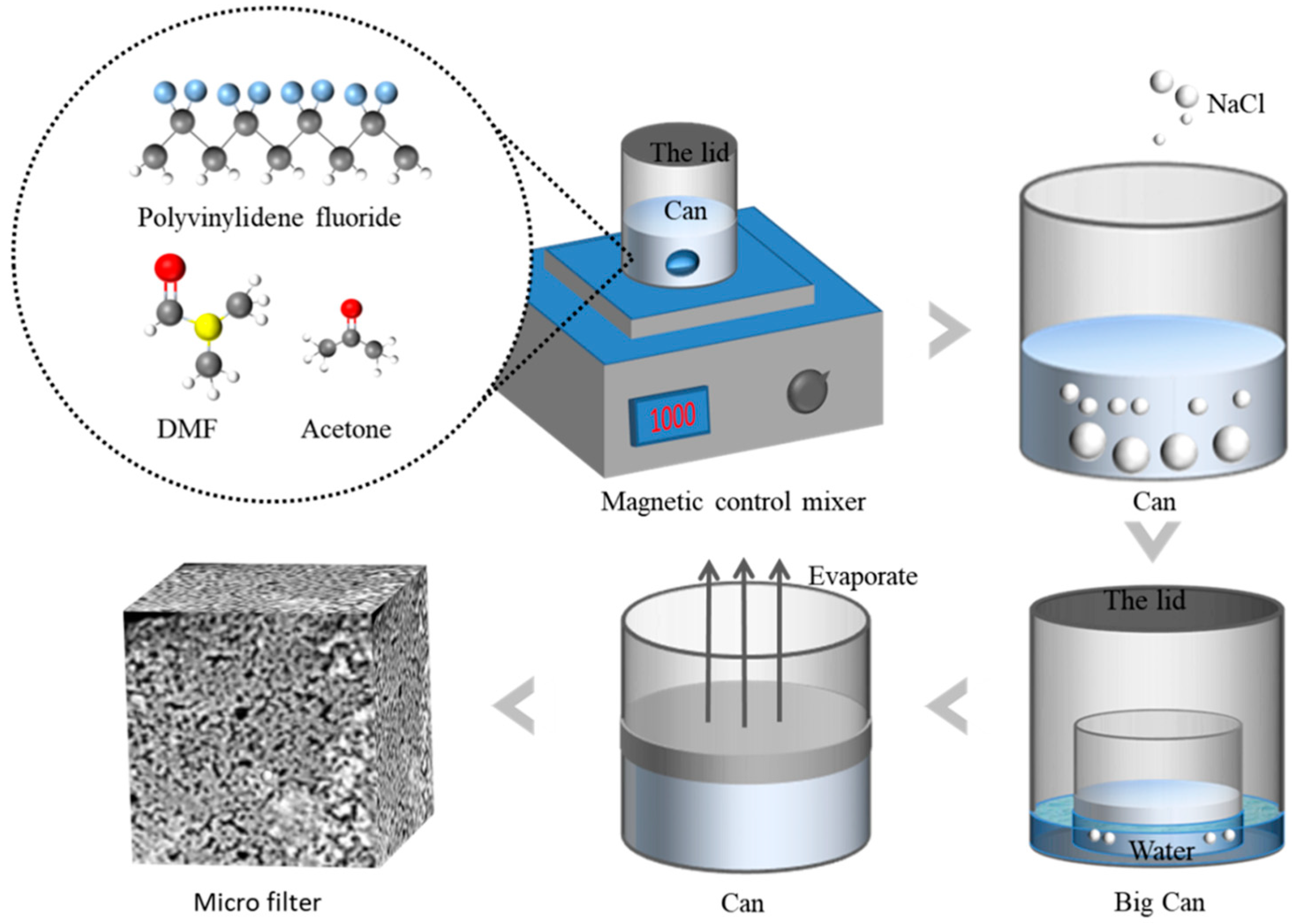
2.2. Preparation of PVDF-MPF by NIPS and VIPS Methods

The PVDF-MPF was prepared using the NIPS and VIPS methods [22]. Figure 1 illustrates the main steps involved in the preparation of PVDF-MPF by adding NaCl-ps. PVDF, DMF, and acetone were placed in sealed cans at a mass percentage of 17%, 33%, and 50%, respectively. It was then magnetically stirred at 75 °C and 1000 rpm for 1 h (FOUR E’S Magnetic Stirring). After the magnetically stirred mixture cooled down and eliminated the bubbles for half an hour, it was poured evenly into five open cans labeled Solution A, Solution B, Solution C, Solution D, and Solution E. Then, different masses of NaCl-ps were added to Solution B, Solution C, Solution D, and Solution E so that the mass ratios of NaCl-ps in Solutions B, C, D, and E were 1 wt%, 5 wt%, 10 wt%, and 20 wt%, respectively, and Solution A was not added NaCl-ps. Then 0.65 g of the five mixtures were removed from Solutions B, C, D, E, and A, packed into five small open cans, and labeled with the original label. The five small cans were then placed into a 200 mL sealed beaker containing 50 mL water. The five small cans were suspended in this 200 mL sealed beaker, and the mixtures in the five cans were guaranteed not to come into direct contact with water. The 200 mL beaker with 50 mL of water was sealed and had five small open cans inside, so water vapor naturally evaporated into the mixture of five open cans. After three days, the five cans were transferred to atmospheric conditions, and the remaining solvent evaporated for another three days. The resulting PVDF-MPFs were alternately washed three times with ethanol and deionized water to remove solvents and NaCl-ps, ensure cleanliness, and evaporate under natural conditions for a day.

2.3. Impurity Filtration Test of Two Kinds of PVDF-MPFs

Figure 2 demonstrates a schematic diagram of the filter device. It consists of a syringe and a PVDF-MPF placed in a conical straw. The large pore at the bottom of the PVDF-MPF is placed in the upper part of the filter unit. The conical straw was inserted into the straw of the syringe. The syringe’s role is to pump air and create negative pressure to accelerate filtration. After the sewage is added, the syringe is pulled apart to generate negative pressure, and the piston shaft of the syringe is jammed with a block to prevent it from bouncing back and realize semi-automatic filtration. A PVDF-MPF without NaCl-Ps was added during preparation, and a PVDF-MPF with 10 wt% of NaCl-Ps was added, filled, and placed in two separate filtration devices. A specific quantity of deionized water was added to carbon ink to simulate sewage. The same carbon ink was used to test those filtration devices respectively. After filtration, the light transmittance of unfiltered carbon ink and two kinds of carbon inks filtered by two PVDF-MPFs without NaCl-Ps and with 10 wt% NaCl-Ps added during the experiment in the wavelength range of 300~1000 nm were measured by the Spectral Transmittance Meter (Shanghai Guangzhao Photoelectric Technology Co., Ltd.). To fit the measuring machine, 5 μL of liquid was placed between two cleaned glass slides (1 cm × 1 cm).

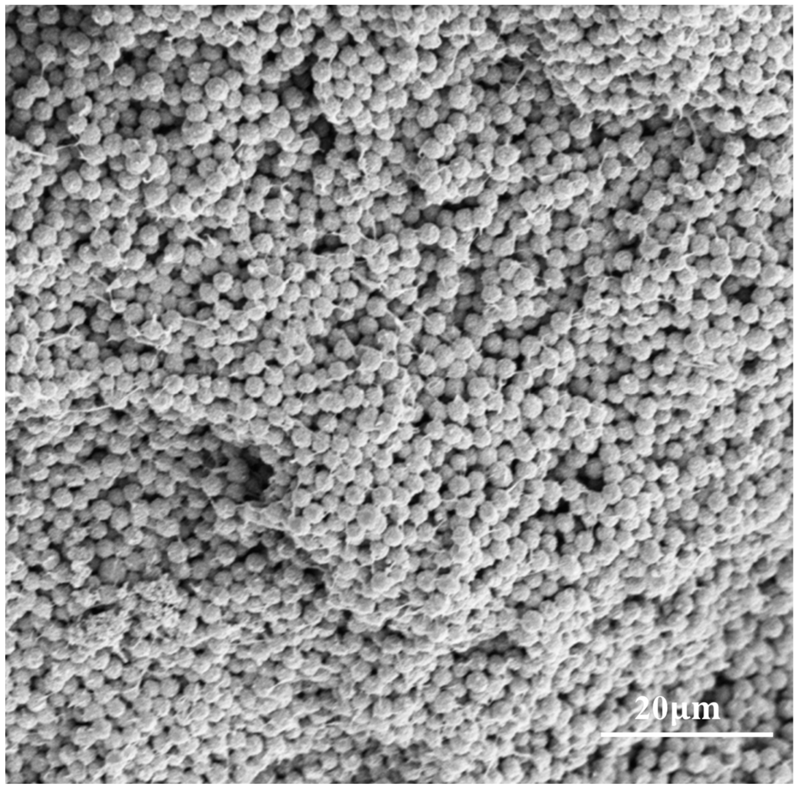
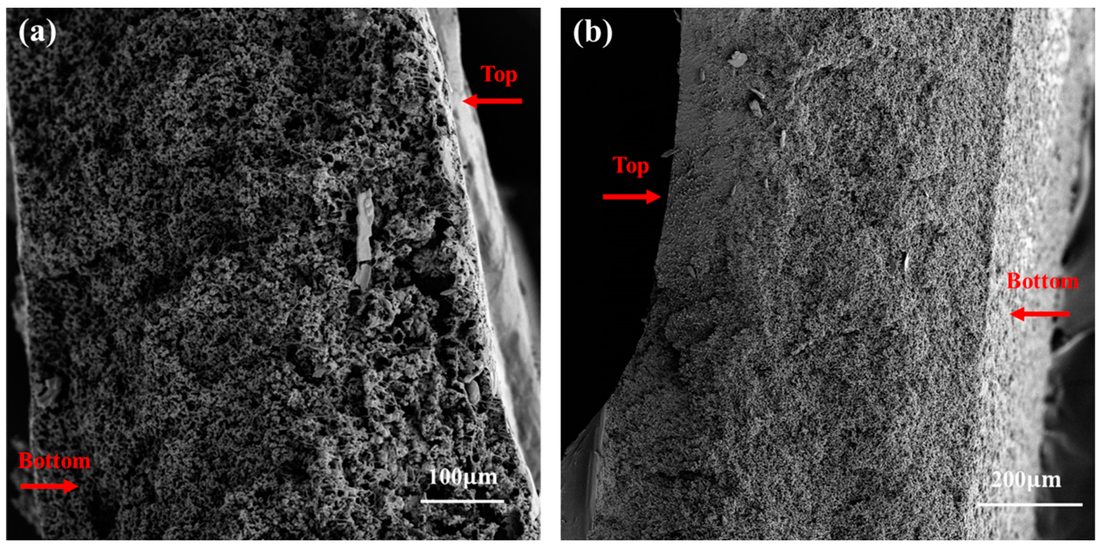
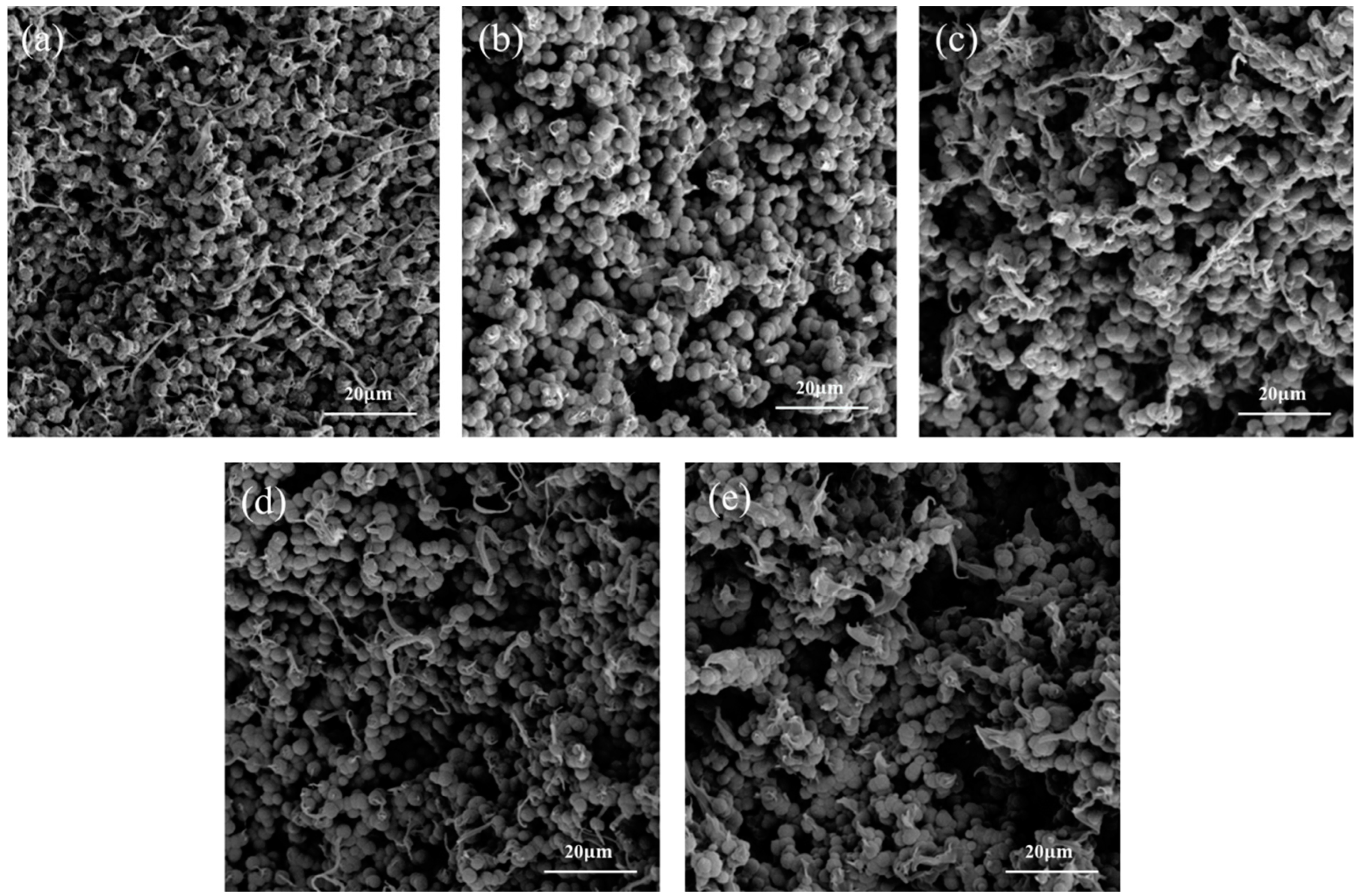
2.4. Morphology of the Five Different PVDF-MPFs

PVDF-MPF samples with different weight of NaCl-ps (1 wt%, 5 wt%, 10 wt%, 20 wt%) and a PVDF-MPF sample without NaCl-ps were prepared by mechanical stress separation method. Those samples were glued to the sample tables with conductive tape, and the unglued sample was blown off with a rubber suction bulb and then sputtered with gold for 30 s to reduce the charge accumulated during the test, thus making the SEM image clearer. SEM images of PVDF-MPF cross sections with different weights of NaCl-ps added PVDF-MPF were obtained. According to the above SEM images, the pore size was measured by the scribing method according to the scale, and the data on pore density (how many pores per square centimeter) were counted.

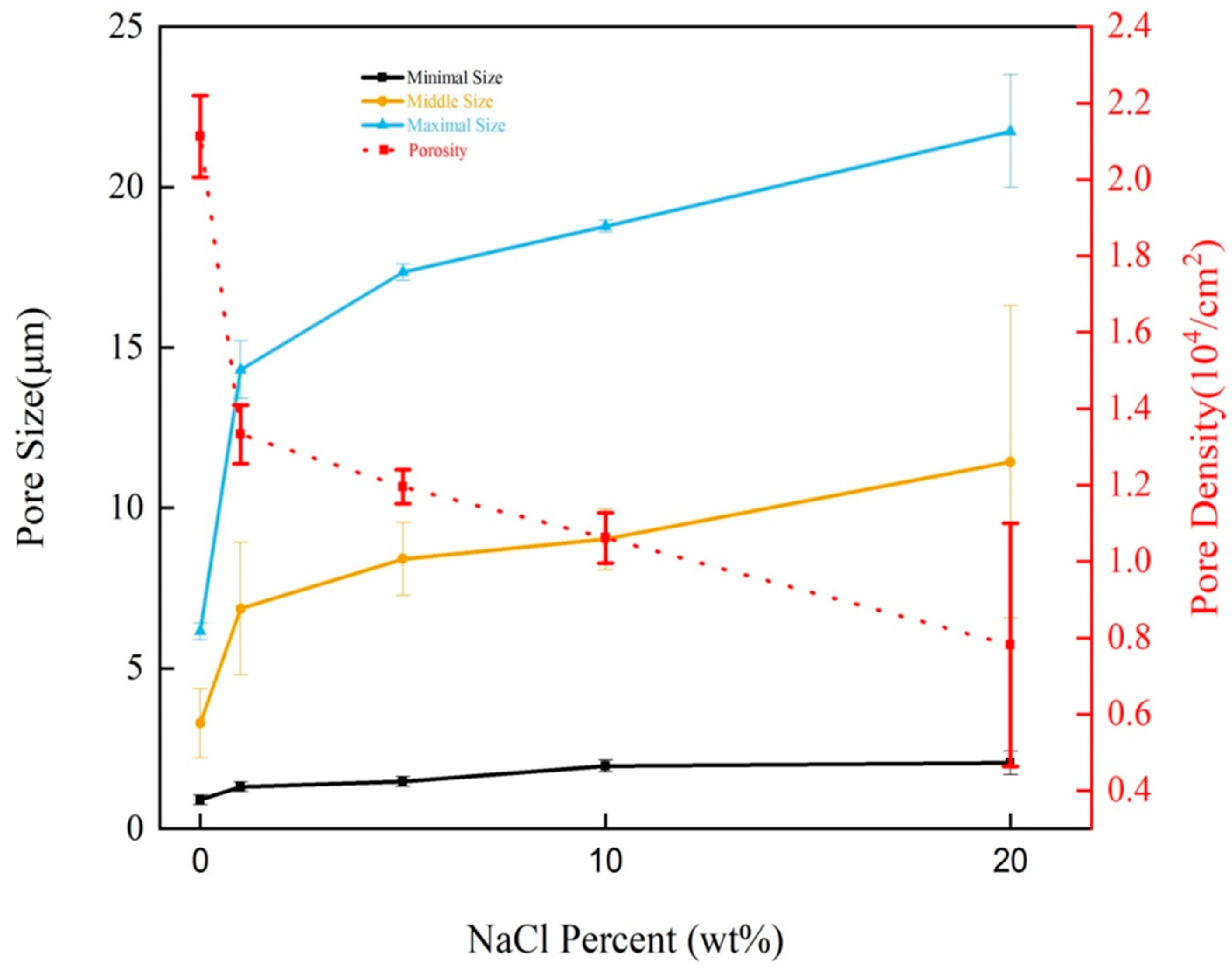
2.5. Porosity of the Five Different PVDF-MPFs

Filter porosity refers to the ratio of the pore volume to the total volume of the filter because pore volume is the volume of a gas and is difficult to measure accurately compared to solids and liquids. But volume could be calculated by mass over density. The pore was filled with very low-density air, so deionized water replaced it in this experiment. Firstly, PVDF-MPF was immersed in deionized water for 4 h. Then it was taken out, and the quality was measured immediately after the water was wiped off the surface with a clean, dust-free cloth. Later, it is then dried in a dryer for 2 h at 45 degrees Celsius, following the direction it took during production, and weighed after the water has been completely removed. Because Li and co-workers propose in this paper that starting at 50 degrees Celsius, the higher the temperature, the smaller the porosity [44]. Finally, according to the mass of PVDF-MDF before and after drying and the density of PVDF and water, the porosity was obtained.

3. Results and Discussions

3.1. Microscopic Processes of NIPS and VIPS

First of all, after adding NaCl-ps to the uniform mixture of DMF, acetone, and PVDF, NaCl-ps remain in a solid suspension state due to its low solubility in DMF and acetone. Yeow and co-workers propose that DMF and Ethanol may affect the porosity of PVDF [45]. On the one hand, with the intrusion of water vapor, DMF, and acetone that is miscible with DMF and acetone, on the other hand, because water is a polar solvent, this leads to a decrease in the solubility of PVDF. It is shown that water is miscible with DMF and acetone, and the solvent used to dissolve PVDF is reduced, leading to its precipitation. With the evaporation of DMF, acetone, and the intrusion of water, the mixture gradually becomes cloudy due to the precipitation of PVDF, and the high density of PVDF leads to its slow precipitation at the bottom of the can. After three days, it is eventually divided into two visible layers. The top layer is the lighter liquid one containing DMF, acetone, and water. This layer can prevent additional water vapor from entering the PVDF, DMF, and acetone mixture layers as well as the bottom layer of the PVDF polymer; vapor easily dissolves in the top liquid layer. NaCl has a density of 2.1 g·cm−3, which is higher than DMF, acetone, and water and is less soluble in those solvents. So, it is located in the lower middle layer. Although NaCl is highly soluble in water (in 100 g of water, 36 g of NaCl can be dissolved at 20 °C), the water content is relatively low and located in the upper layer, and the water does not dissolve uncontacted NaCl, leaving these particles in the layer containing PVDF, resulting in the final PVDF-MPF rich pores. Then, the can is removed from the vapor-filled environment and placed in a well-ventilated and cool environment to completely evaporate the liquid in the top and bottom layers. As the top liquid disappears, pores appear in the PVDF polymer. The top and bottom liquids are connected, so after the liquid evaporates and the gas invades, pores appear and connect. During evaporation, the PVDF polymer also contracted slightly without liquid support and compression of atmospheric pressure. During this process, NaCl-ps can provide some support to stop the contraction process.

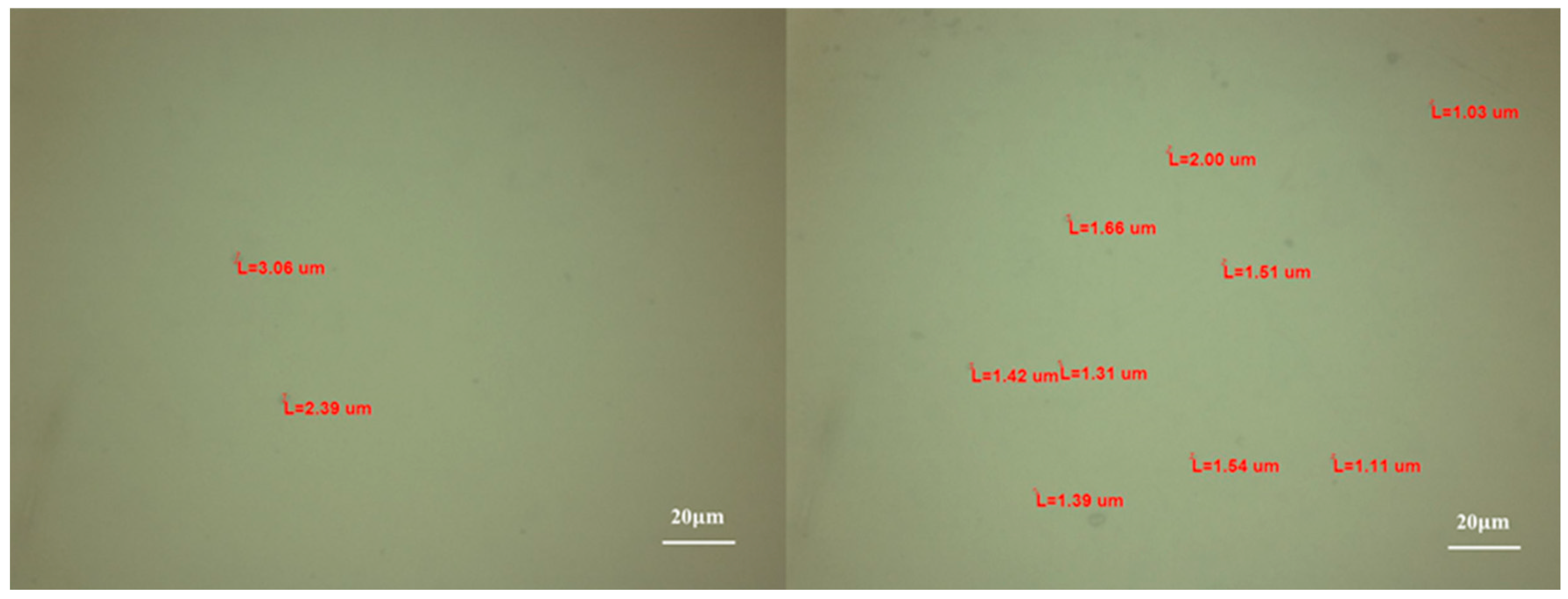
3.2. The Influence of NaCl-ps Size for PVDF-MPF

Figure 3 shows a SEM image of PVDF-MPF without NaCl-ps. It is evident from Figure 3 that the PVDF-MPF consists of spherical PVDF particle accumulation. The spherical PVDF particles have an actual size of about 2.26 μm. Although spherical PVDF particles cannot fill the entire space using hexagonal close-packed or cubic close-packed ways, causing an empty space when PVDF-MPF is piled layer by layer, it does not have large and connected pores useful for filtration. The PVDF-MPF with NaCl-ps added may interface with this dense stacking pattern by introducing defects. This is a key factor affecting the performance of PVDF-MPF filters.
In our experiment, the sizes of NaCl-ps were not uniform, with diameters ranging from 1.03 μm to 3.06 μm. These measurements were obtained using the software accompanying the light microscope in Figure 4.
According to common sense, heavy particles settle at the bottom of a mixture, while light particles rise to the top; heavier NaCl-ps have larger diameters than lighter NaCl-ps. So, NaCl-ps with larger diameters will settle at the bottom of the PVDF mixture, which results in a larger pore size at the bottom of PVDF-MPF. The SEM images of PVDF-MPF cross-sections at different heights can reflect the actual pores’ distribution, size, and porosity. Figure 5a,b are SEM images of the middle and bottom of the PVDF-MPF with 10 wt% NaCl-ps added during the production process, respectively. The results show that both large and small pores exist in these two regions simultaneously. But there are bigger and more pores at the bottom. The maximal pore size of Figure 5a,b are separately 10.03 μm and 16.23 μm, respectively. According to natural settlement, most NaCl-ps are concentrated in the bottom of the PVDF-MPF, with a small amount of NaCl-ps in the middle. So, the bottom pore size is larger than the middle pore size.
According to the structure of the PVDF-MPF prepared by adding NaCl-ps, it was placed upside down in a conical straw and connected to the syringe. Negative pressure can be generated when pulling the syringe, and semi-automatic filtration can be achieved when fixing the syringe. This filter aperture from large to small structures can effectively purify sewage. Large pores allow large, middle, and small particles to pass through. Middle-size pores only allow middle and small particles to go through. Large pores can pass sewage faster through than smaller ones, so the filter is arranged so that the aperture is large to the small structure. In addition, because PVDF polymer can be stretched and contracted, small pores can be destroyed by big particles under negative pressure conditions. From the two aspects of speed and filtration effect, the above structure is very suitable. This structure can gradually remove the sewage particles from large to small, with large sewage particles being removed at the top of the filter and small particles in the bottom area, and it finally purifies the water from sewage to pure water.
Figure 6 is an SEM image of the PVDF-MPF vertical slope with 10 wt% NaCl-ps added. There are large pores around 21.31 μm on the top of PVDF-MPF, which violates the distribution law of its pore size. It may be the influence of NIPS and VIPS. These two processes react violently around the contact surface of the air and mixture, resulting in an error in the PVDF-MPF pore size distribution. So, PVDF nanoparticles are not natural. The unstable contact surface causes PVDF-MPF surface defects to be more severe than in the middle and bottom, manifested as larger pores at the top. It is worth noting that there are tiny pores around big pores in Figure 6a,b because the edges of the large pores are composed of PVDF particles, and aggregated PVDF particles always form tiny pores. So, there are always small pores attached to large pores. But there are not necessarily large pores around small pores.

3.3. The Effect of Adding Weight of NaCl-ps on PVDF-MPF

It can be seen from Figure 7 that the increase of NaCl-ps addition leads to the decrease of pore density because more NaCl-ps occupy the position of PVDF, more defects will be caused, but after more defects, multiple pores will fuse into a large pore, resulting in a decrease in pore density. As can be seen from Figure 7a, PVDF-MPF without NaCl-ps added contains more than 20,000 pores per cm−2. Figure 7b–e demonstrates the porosity of PVDF-MPF decreases in general with the increase of NaCl-ps concentration. The PVDF-MPF without NaCl-ps added has the highest pore density among the five groups because PVDF particles can be viewed as a spherical model, and the accumulation of the spherical model will produce a lot of pores. When NaCl-ps is not added, PVDF particles will be tightly packed under natural conditions, and small pores will not merge into larger pores. Therefore, the number of micropores smaller than 1 μm in the PVDF-MPF without NaCl-ps added is significantly higher than that in PVDF-MPF with NaCl-ps added.
A SEM image of the vertical section can reflect the actual pores’ distribution, size, and density. Figure 8a is the SEM image of the PVDF-MPF vertical slope without NaCl-ps added, which shows that the distribution of sample pores is uniform. Figure 8b–e is a SEM image in vertical slopes for PVDF-MPFs of different weight NaCl-ps added. The morphology of PVDF-MPF was changed by adding different weights of NaCl-ps to the PVDF polymer mixture. After ding NaCl-ps, the uniform sphere model is changed to a mixed sphere model of with different particle sizes. From the homogeneous spherical packing model, the pore size is only related to the size and packing mode of spherical particles at the same ambient temperature. Controlling the variables except the particle size to be constant and considering the non-interacting spherical model, pore size increases with the particle size increasing. Therefore, in the analysis of two-particle mixed systems, only one kind of nanoparticle is considered as the limit case. In other words, the pore sizes of PVDF particles and NaCl-ps hybrid systems are between those of pure PVDF particles and pure NaCl-ps. It can be speculated that with the increase of the mass of NaCl-ps, the pore size of PVDF-MPF increases continuously from the pore size formed by pure PVDF particles to that formed by pure NaCl-ps. In general, the sphere model produces pores that are smaller than the sphere particles because once it is large enough to hold a particle, there will naturally be other particles in the position. NaCl-ps may aggregate with each other to form larger particles that interact with PVDF to increase the pore size of the PVDF-MPF.
As can be seen from Figure 7e, the PVDF-MPF with 20 wt% NaCl-ps added has obvious stratification compared with Figure 8a–d. These PVDF particles at the bottom are larger than those particles at the top in Figure 8e, and these particle sizes at the bottom are more than 56.25 μm, which is much larger than NaCl-ps. This can be seen as a mutational process because there is a clear dividing line in the middle region. This may be due to the accumulation and fusion of NaCl-ps at the bottom area to form large pores of PVDF-MPF, which had no filtering effect on the particles in the carbon ink. It is also because successive continuous NIPS and VIPS processes are not prone to mutation, and this factor can be excluded. A large number of NaCl-ps with large volumes formed at the bottom, forming large pores of PVDF-MPF, which had no filtering effect on the particles in the carbon ink. PVDF-MPFs added with 1 wt% to 10 wt% NaCl-ps do not have this mutant process. The mutant process will seriously affect the quality of PVDF-MPF, so the added weight of NaCl-ps should be below 20 wt%.
It can be seen from Figure 9 that with the increase of NaCl-ps concentration, the minimal, middle, and maximal pore sizes of PVDF-MPF tend to increase. In the same condition, the pore density of PVDF-MPF decreases with the increase of NaCl-ps addition. From no NaCl-ps to the addition of 1 wt% NaCl-ps, the pore sizes increased significantly (6.15 μm to 14.3 μm), the pore density decreased sharply (2.11 × 104 cm−2 to 1.33 × 104 cm−2). With the increase of NaCl-ps addition, the changes of these parameters are not as obvious as that from no NaCl-ps addition to 1 wt% NaCl-ps addition, but the change trends are consistent.

3.4. Water Absorption of PVDF-MPF Added with Different NaCl-ps Weights

Table 1 shows that with the increase in weight of NaCl-ps, PVDF-MPF water absorption improves in general. The porosity (ε) is defined as below:
ε = ( W w W d ) / ρ i ( W w W d ρ i ) + ( W d ρ p )
ε is the porosity of the PVDF-MPF [12]. Ww and Wd are the weights of wet PVDF-MPF and dry PVDF-MPF, respectively. ρi and ρp represent the density of water (1.00 g·cm−3) and solid PVDF (1.785 g·cm−3), respectively. The porosity of the PVDF-MPF obtained by adding 1 wt% NaCl-ps is significantly higher than that of the PVDF-MPF without NaCl-ps added. Eventually, the porosity reaches 77.29% when the weight percent of NaCl-ps reaches 20 wt%. If pores in PVDF-MPF are connected to form capillaries that can hold water, the calculated porosity will become very high, which also reflects the pore connectivity of PVDF-MPF. The higher the porosity of PVDF-MPF, the faster it filters the carbon ink. Though the porosity obtained from the water absorption rate cannot show the microstructure of PVDF-MPF in detail, it can show the proportion of connected pores in PVDF-MPF, which is very helpful for carbon ink filtration. According to the capillary phenomenon, fine capillaries can drag water higher in the vertical ground direction than coarse capillaries. Large capillaries can reduce the effectiveness of water storage, so the porosity measured in the water absorption test will not include large capillaries that do not have a significant role in filtering carbon ink sewage.
Table 1. Water absorption of different PVDF-MPFs.
NaCl-ps
Concentration (wt%)
Weight of PVDF-MPFs before Being Filled with Water (g)Weight of PVDF-MPFs after Being Filled with Water (g) Porosity (%)
00.05030.05040.35
10.02050.041164.21
50.02300.048366.26
100.07120.148866.05
200.01830.053277.29

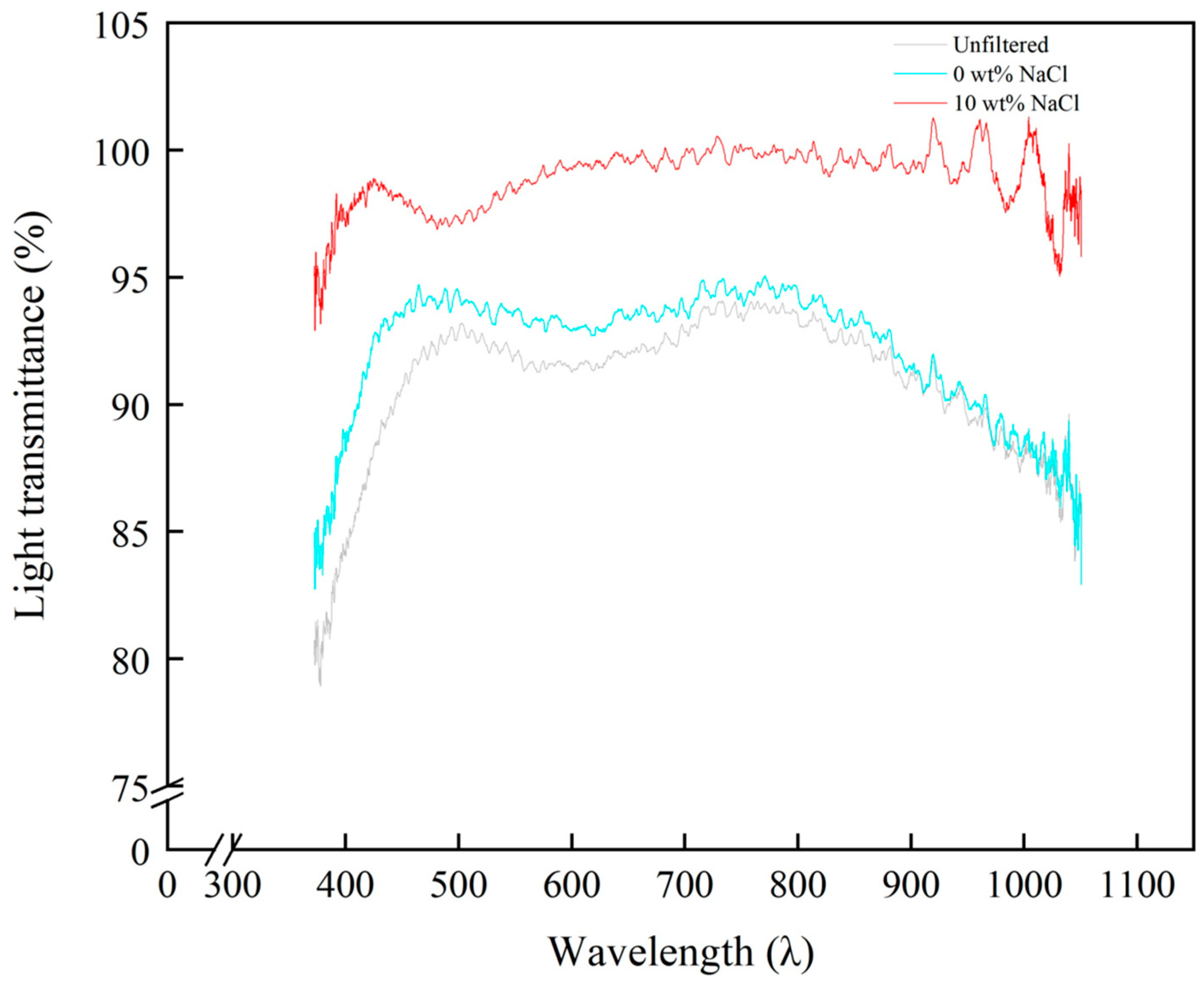
3.5. Performance Test of PVDF-MPF for Carbon Ink Purification

To verify the purification capacity of PVDF-MPF with NaCl-ps or without NaCl-ps, carbon ink containing a large number of small solid particles is taken as an example to test the purification capacity of MPF. Figure 10a shows the simple purifying units made by the PVDF-MPF and a syringe. Figure 10b is a photo of three kinds of unfiltered carbon ink: the carbon ink filtered by PVDF-MPF with 10 wt% NaCl-ps added and the carbon ink filtered by PVDF-MPF without NaCl-ps added. Figure 11 displays the light transmittance of image-unfiltered carbon ink, the carbon ink filtered by PVDF-MPF with 10 wt% NaCl-ps added, and the carbon ink filtered by PVDF-MPF without NaCl-ps added at different wavelengths. At 550 nm wavelength, the light transmittance of unfiltered carbon ink, the carbon ink filtered by PVDF-MPF with 10 wt% NaCl-ps added, and the carbon ink filtered by PVDF-MPF without NaCl-ps added are 91.86%, 98.66%, and 93.66%, respectively. Compared with the light transmittance of unfiltered carbon ink, the light transmittance of the carbon ink filtered by the two different PVDF-MPFs increased. It means that both of the different PVDF-MPFs can remove particles from carbon ink. Although in theory, PVDF-MPF without NaCl-ps added has smaller and more pores than the PVDF-MPF with 10 wt% NaCl-ps in Figure 9, in practice, PVDF- with 10 wt% NaCl-ps added has a more vital ability to purify carbon ink than PVDF-MPF without NaCl-ps in actuality. This reason may be that pore size and pore density only reflect one factor, and porosity is another more important factor affecting carbon ink purification. The water absolution test shows that PVDF-MPF without NaCl-ps added has a very low porosity. It means that without the addition of NaCl-ps, PVDF-MPF contains very few capillaries. At the same time, because PVDF-MPF without NaCl-ps added is very hard, there is always a gap between it and the filtration equipment, so more carbon ink is filtered directly through this gap. PVDF-MPF with 10 wt% NaCl-ps added has a high porosity, allowing more carbon ink to pass through its internal capillary tubes to achieve a good filtration effect. Corrosive substances in carbon ink may damage the structure of PVDF-MPF and affect the filtration effect. Repeatability affects the replacement time of PVDF-MPF. The carbon ink used in this manuscript is non-corrosive, and subsequent experiments can be carried out according to the direction of corrosion resistance.

4. Conclusions

In this paper, PVDF-MPF with added NaCl-ps was prepared by using VIPS and NIPS methods. Compared to the standard method of preparing PVDF-MPF, this method increases the step of adding NaCl-ps to the mixture of PVDF, DMF, and acetone. Additionally, a simple, inexpensive, and convenient filtration device using PVDF-MPF was proposed. The main findings of the paper are as follows: Firstly, the pore size, pore density, and porosity images of PVDF-MPF vertical slopes with different NaCl-ps masses and heights were measured and statistically analyzed using SEM images. The results showed that the addition of 10 wt% NaCl-ps resulted in a maximum intermediate pore size of 4.23 microns for PVDF-MPF, while the absence of NaCl-ps led to a maximum pore size of 9.72 microns. The minimum pore size was 0.76 microns and 1.76 microns, respectively. Secondly, the addition of NaCl-ps also increased the porosity of PVDF-MPF. The porosity of PVDF-MPF without 10 wt% NaCl-ps was measured to be 0.35% and 66.05% using the water absorption method, respectively. The porosity results indicate that NaCl-ps can significantly enhance the porosity of PVDF-MPF so that more carbon ink can be effectively filtered through its internal pores. Finally, PVDF-MPF without NaCl-ps and with 10 wt% NaCl-ps were added to simulate the sewage purification process. The light transmittance of the filtered carbon ink to 550 nm was 93.66% and 98.66%, respectively. Adding Nacl-ps in the production process can enhance the filtration effectiveness of PVDF-MPF on carbon ink. In summary, incorporating mobile particles into PVDF-MPF is a straightforward and efficient method to enhance the purification effectiveness of PVDF-MPF. This approach encourages researchers to explore the integration of different particles with MPF.

Author Contributions

L.P.: Data curation (lead); writing—original draft (lead); writing—review and editing (equal). P.L.: Conceptualization (lead); writing—original draft (equal); writing—review and editing (lead). J.H.: writing—original draft (equal). Q.G.: Supervision (lead); conceptualization (equal). J.Y.: Data curation (equal); supervision (equal). All authors have read and agreed to the published version of the manuscript.

Funding

This research was funded by the National Natural Science Foundation of China (No. 62104033), the Key Scientific Research Project of the Department of Education of Guangdong Province (2021ZDZX1052), and the Science and Technology Project Foundation of Zhongshan City (2022B2020 and 2022B2006).

Institutional Review Board Statement

Not applicable.

Informed Consent Statement

Not applicable.

Data Availability Statement

The datasets generated during and/or analyzed during the current study are not publicly available but are available from the corresponding author upon reasonable request.

Conflicts of Interest

The author has no conflicts of interest to declare.

References

  1. Alsulaili, A.; Al-Harbi, M.; Elsayed, K. The influence of household filter types on quality of drinking water. Process Saf. Environ. Protect. 2020, 143, 204–211. [Google Scholar] [CrossRef]
  2. Subbiah, T.; Bhat, G.S.; Tock, R.W.; Pararneswaran, S.; Ramkumar, S.S. Electrospinning of nanofibers. J. Appl. Polym. Sci. 2005, 96, 557–569. [Google Scholar] [CrossRef]
  3. Lindqvist, J.; Malmstrom, E. Surface modification of natural substrates by atom transfer radical polymerization. J. Appl. Polym. Sci. 2006, 100, 4155–4162. [Google Scholar] [CrossRef]
  4. Lal, R. World Water Resources and Achieving Water Security. Agron. J. 2015, 107, 1526–1532. [Google Scholar] [CrossRef]
  5. Wotton, R.S. Water purification using sand. Hydrobilogia 2002, 469, 193–201. [Google Scholar] [CrossRef]
  6. Melian, J.A.H.; Arnana, J.; Gonzalez Diaz, O.; Aguiar Bujalance, M.E.; Dona Rodriguez, J.M. Effect of stone filters in a pond-wetland system treating raw wastewater from a university campus. Desalination 2009, 237, 277–284. [Google Scholar] [CrossRef]
  7. Hubbel, L.; Elmore, A.C.; Reidmeyer, M. Comparison of a native clay soil and an engineered clay used in experimental ceramic pot filter fabrication. Water Sci. Technol.-Water Supply 2015, 15, 569–577. [Google Scholar] [CrossRef]
  8. Masmali, I.; Khalid, A.; Shuaib, U.; Razaq, A.; Garg, H.; Razzaque, A. On Selection of the Efficient Water Purification Strategy at Commercial Scale Using Complex Intuitionistic Fuzzy Dombi Environment. Water 2023, 10, 1907. [Google Scholar] [CrossRef]
  9. Sarkar, S.; Tribedi, P.; Das Gupta, A.; Saha, T.; Sil, A.K. Microbial Functional Diversity Decreases with Sewage Purification in Stabilization Ponds. Waste Biomass Valorization 2017, 8, 417–423. [Google Scholar] [CrossRef]
  10. Losch, P.; Anotonyuk, S. Selective particle deposition at cross-flow filtration with constant filtrate flux. Powder Technol. 2021, 388, 305–317. [Google Scholar] [CrossRef]
  11. Templeton, E.J.; Salin, E.D. A novel filtration method integrated on centrifugal microfluidic devices. Microfluid. Nanofluid. 2014, 17, 245–251. [Google Scholar] [CrossRef]
  12. Field, R.W.; Wu, D.; Howell, J.A.; Gupta, B.B. Critical flux concept for microfiltration fouling. J. Membr. Sci. 1995, 100, 259–272. [Google Scholar] [CrossRef]
  13. Kang, P.K.; Shah, D.O. Filtration of nanoparticles with dimethyldioctadecylammonium bromide treated microporous polypropylene filters. Langmuir 1997, 13, 1820–1826. [Google Scholar] [CrossRef]
  14. Hong, S.K.; Elimelech, M. Chemical and physical aspects of natural organic matter (NOM) fouling of nanofiltration membranes. J. Membr. Sci. 1997, 132, 159–181. [Google Scholar] [CrossRef]
  15. Hilal, N.; Al-Zoubi, H.; Darwish, N.A.; Mohammad, A.W.; Abu Arabi, M. A comprehensive review of nanofiltration membranes: Treatment, pretreatment, modelling, and atomic force microscopy. Desalination 2004, 170, 281–308. [Google Scholar] [CrossRef]
  16. Aryanti, P.T.; Nugroho, F.A.; Widiasa, I.N.; Sutrisna, P.D.; Wenten, I.G. Preparation of highly selective PSf/ZnO/PEG400 tight ultrafiltration membrane for dyes removal. J. Membr. Sci. 2022, 139, e52779. [Google Scholar] [CrossRef]
  17. Zhao, Z.Z.; Li, J.Q.; Yuan, X.Y.; Li, X.; Zhang, Y.Y.; Sheng, J. Preparation and properties of electrospun poly(vinylidene fluoride) membranes. J. Appl. Polym. Sci. 2005, 97, 466–474. [Google Scholar] [CrossRef]
  18. Feng, C.; Khulbe, K.C.; Matsuura, I.; Gopal, R.; Kaur, S.; Rarnakrishna, S.; Khayet, M. Production of drinking water from saline water by air-gap membrane distillation using polyvinylidene fluoride nanofiber membrane. J. Membr. Sci. 2008, 311, 1–6. [Google Scholar] [CrossRef]
  19. Liao, Y.; Wang, R.; Tian, M.; Qiu, C.Q.; Fane, A.G. Fabrication of polyvinylidene fluoride (PVDF) nanofiber membranes by electro-spinning for direct contact membrane distillation. J. Membr. Sci. 2012, 425, 30–39. [Google Scholar] [CrossRef]
  20. Liu, P.; Wang, J.H.; Chen, J.; Liu, L.M.; Wang, H.H.; Zeng, B.Q.; Chi, F. A new structure of flexible oled with copper nanowire anode and graphere oxide/PEDOT: PSS anode buffer layer. Surf. Rev. Lett. 2020, 27, 1950171. [Google Scholar] [CrossRef]
  21. Wang, Y.X.; Liu, P.; Wang, H.H.; Zeng, B.Q.; Wang, J.H.; Chi, F. Flexible organic light-emitting devices with copper nanowire composite transparent conductive electrode. J. Mater. Sci. 2018, 54, 2343–2350. [Google Scholar] [CrossRef]
  22. Xu, H.R.; Liu, P.; Huang, B.; Jiang, X.W.; Gao, Q.G.; Liu, L.M. Preparation of Double-Layer Crossed Silver Nanowire Film and Its Application to OLED. Coatings 2022, 12, 26. [Google Scholar] [CrossRef]
  23. Trommer, K.; Palitzsch, W.; Morgenstern, B.; Loser, U. Microporous PVC—New Membrane Material for Application in Microfiltration. Chem. Ing. Tech. 2012, 84, 63–69. [Google Scholar] [CrossRef]
  24. Kostov, G.; Christova, N.; Charadjiev, P. Microporous membrane filters on the basis of poly(tetrafluoroethylene). Acta Polym. 1991, 42, 499–503. [Google Scholar] [CrossRef]
  25. Eykens, L.; De Sitter, K.; Dotremont, C.; Pinoy, L.; Van der Bruggen, B. Membrane synthesis for membrane distillation: A review. Sep. Purif. Technol. 2017, 182, 36–51. [Google Scholar] [CrossRef]
  26. Ariono, D.; Aryanti, P.T.P.; Hakim, A.N.; Subagjo, S.; Wenten, I.G. Determination of Thermodynamic Properties of polysulfone/PEG Membrane Solutions Based on Flory-Huggins Model. AIP Conf. Proc. 2017, 1840, 090008. [Google Scholar]
  27. Jin, T.T.; Zhao, Z.P.; Chen, K.C. Preparation of a poly(vinyl chloride) ultrafiltration membrane through the combination of thermally induced phase separation and non-solvent-induced phase separation. J. Appl. Polym. Sci. 2015, 133, 42953. [Google Scholar] [CrossRef]
  28. Matsuyama, H.; Teramoto, M.; Nakatani, R.; Maki, T. Membrane formation via phase separation induced by penetration of nonsolvent from vapor phase. I. Phase diagram and mass transfer process. J. Appl. Polym. Sci. 1999, 74, 159–170. [Google Scholar] [CrossRef]
  29. Gu, M.H.; Zhang, J.; Wang, X.L.; Ma, W.Z. Crystallization behavior of PVDF in PVDF-DMP system via thermally induced phase separation. J. Appl. Polym. Sci. 2006, 102, 3714–3719. [Google Scholar] [CrossRef]
  30. Hernandez, A.; Calvo, J.I.; Pradanos, P.; Tejerina, F. Pore size distributions in microporous membranes. A critical analysis of the bubble point extended method. J. Membr. Sci. 1996, 112, 1–12. [Google Scholar] [CrossRef]
  31. Taurozzi, J.S.; Arul, H.; Bosak, V.Z.; Burban, A.F.; Voice, T.C.; Bruening, M.L.; Tarabara, V.V. Effect of filler incorporation route on the properties of polysulfone-silver nanocomposite membranes of different porosities. J. Membr. Sci. 2008, 325, 58–68. [Google Scholar] [CrossRef]
  32. Abdel-Karim, A.; Luque-Alled, J.M.; Leaper, S.; Alberto, M.; Fan, X.; Vijayaraghavan, A.; Gad-Allah, T.A.; El-Kalliny, A.S.; Szekely, G.; Ahmed, S.I.A.; et al. PVDF membranes containing reduced graphene oxide: Effect of degree of reduction on membrane distillation performance. Desalination 2019, 452, 196–207. [Google Scholar] [CrossRef]
  33. Julian, H.; Sutrisna, P.D.; Hakim, A.N.; Harsono, H.O.; Hugo, Y.A.; Wenten, I.G. Nano-silica/polysulfone asymmetric mixed-matrix membranes (MMMs) with high CO2 permeance in the application of CO2/N2 separation. Polym. Plast. Technol. Mater. 2019, 58, 678–689. [Google Scholar] [CrossRef]
  34. Gethard, K.; Sae-Khow, O.; Mitra, S. Water Desalination Using Carbon-Nanotube-Enhanced Membrane Distillation. ACS Appl. Mater. Interfaces 2011, 3, 110–114. [Google Scholar] [CrossRef] [PubMed]
  35. Sharma, M.; Mondal, P.; Chakraborty, A.; Kuttippurath, J.; Purkait, M. Effect of different molecular weight polyethylene glycol on flat sheet cellulose acetate membranes for evaluating power density performance in pressure retarded osmosis study. J. Water Process Eng. 2019, 30, 100632. [Google Scholar] [CrossRef]
  36. Chen, F.Z.; Lu, Y.; Liu, X.; Song, J.L.; He, G.J.; Tiwari, M.K.; Carmalt, C.J.; Parkin, I.P. Table Salt as a Template to Prepare Reusable Porous PVDF-MWCNT Foam for Separation of Immiscible Oils/Organic Solvents and Corrosive Aqueous Solutions. Adv. Funct. Mater. 2017, 27, 1702926. [Google Scholar] [CrossRef]
  37. Bian, W.B.; Zhang, R.X.; Chen, X.H.; Zhang, C.X.; Meng, M. Three-Dimensional Porous PVDF Foam Imprinted Membranes with High Flux and Selectivity toward Artemisinin/Artemether. J. Mol. 2023, 28, 7452. [Google Scholar] [CrossRef] [PubMed]
  38. Wang, H.; Jin, X.Y.; Wu, H.B. Adsorption and Desorption Properties of Modified Feather and Feather/PP Melt-Blown Filter Cartridge of Lead Ion (Pb2+). J. Appl. Polym. Sci. 2015, 132, 41555. [Google Scholar] [CrossRef]
  39. Arteta, S.M.; Vera, R.; Perez, L.D. Hydrophobic cellulose fibers via ATRP and their performance in the removal of pyrene from water. J. Appl. Polym. Sci. 2017, 134, 44482. [Google Scholar] [CrossRef]
  40. Wu, Y.L.; Kong, Y.; Lin, X.; Liu, W.H.; Xu, J.P. Surface-modified hydrophilic membranes in membrane distillation. J. Membr. Sci. 1992, 72, 189–196. [Google Scholar] [CrossRef]
  41. Jung, J.; Shin, Y.; Choi, Y.J.; Sohn, J.; Lee, S.; An, K. Hydrophobic surface modification of membrane distillation (MD) membranes using water-repelling polymer based on urethane rubber. Desalination Water Treat. 2016, 57, 10031–10041. [Google Scholar] [CrossRef]
  42. Sun, Y.L.; Zong, Y.; Yang, N.; Zhang, N.; Jiang, B.; Zhang, L.H.; Xiao, X.M. Surface hydrophilic modification of PVDF membranes based on tannin and zwitterionic substance towards effective oil-in-water emulsion separation. Sep. Purif. Technol. 2019, 234, 116015. [Google Scholar] [CrossRef]
  43. Ruan, L.X.; Yao, X.N.; Chang, Y.F.; Zhou, L.Q.; Qin, G.W.; Zhang, X.M. Properties and Applications of the beta Phase Poly(vinylidene fluoride). Polymer 2018, 10, 228. [Google Scholar] [CrossRef]
  44. Li, W.B.A.; Li, X.Z.; Xie, X.H.; Yuan, A.B.; Xia, B.J. Effect of drying temperature on a thin PVDF-HFP/PET composite nonwoven separator for lithium-ion batteries. Ionics 2017, 23, 929–935. [Google Scholar] [CrossRef]
  45. Yeow, M.L.; Liu, Y.T.; Li, K. Morphological study of poly(vinylidene fluoride) asymmetric membranes: Effects of the solvent, additive, and dope temperature. J. Appl. Polym. Sci. 2004, 92, 1782–1789. [Google Scholar] [CrossRef]
Figure 1. Schematic of PVDF-MPF production process. The capacity of the beaker is 200 mL. The diameter and height of the can is 2 cm and 5 cm.
Coatings 14 00196 g001
Figure 2. A filtration device: (a) schematic diagram; (b) Photographic image.
Coatings 14 00196 g002
Figure 3. A SEM image of PVDF-MPF without NaCl-ps added.
Coatings 14 00196 g003
Figure 4. An optical microscope photograph of NaCl-ps.
Coatings 14 00196 g004
Figure 5. SEM Image at different heights of PVDF-MPF assisted by NaCl-ps with a concentration of 10 wt%: (a) Middle and (b) Bottom.
Coatings 14 00196 g005
Figure 6. A SEM image for the vertical slope of PVDF-MPF with NaCl-ps added. (a) No NaCl-ps added. (b) With 10 wt% NaCl-ps added. Top indicates the naturally formed top of the production process.
Coatings 14 00196 g006
Figure 7. SEM images of PVDF-MPFs with different weights of NaCl-ps added: (a) without NaCl-ps added, (be) with NaCl-ps added, and the weight percentage of NaCl-ps added are (b) 1 wt%, (c) 5 wt%, (d) 10 wt%, and (e) 20 wt%, respectively.
Coatings 14 00196 g007
Figure 8. SEM images of PVDF-MPFs vertical slope with different added weight percentage of NaCl-ps: (a) without NaCl-ps added, (be) with NaCl-ps added, and the NaCl-ps weight percentage are (b) 1 wt%, (c) 5 wt%, (d) 10 wt% and (e) 20 wt%, respectively.
Coatings 14 00196 g008
Figure 9. Pore sizes and pore density of PVDF-MPFs under the addition of NaCl-ps with different weight percentages.
Coatings 14 00196 g009
Figure 10. Photo images of PVDF-MPF carbon ink purification test. (a) Filtering process, (b) Unfiltered carbon ink, the carbon ink filtered by PVDF-MPF with 10 wt% NaCl-ps added and the carbon ink filtered by PVDF-MPF without NaCl-ps added.
Coatings 14 00196 g010
Figure 11. Light transmittance of different liquids: unfiltered carbon ink, the carbon ink filtered by PVDF-MPF with 10 wt% NaCl-ps added, and the carbon ink filtered by PVDF-MPF without NaCl-ps added.
Coatings 14 00196 g011
Disclaimer/Publisher’s Note: The statements, opinions and data contained in all publications are solely those of the individual author(s) and contributor(s) and not of MDPI and/or the editor(s). MDPI and/or the editor(s) disclaim responsibility for any injury to people or property resulting from any ideas, methods, instructions or products referred to in the content.

