Article

Friction Evolution of Graphite Bearing Impregnated with Polymer Subjected to Vibration Fretting at High Temperature

1
Institut Pprime UPR 3346, CNRS–ENSMA-IUT-Université de Poitiers, Bd. M. et P. Curie, Téléport 2, BP 30179, 86962 Chasseneuil, France
2
Department of Mechanical Engineering, University of Louisiana-Lafayette, Lafayette, LA 70504, USA
3
GREMAN UMR CNRS 7347, Université de Tours, INSA Centre Val de Loire, 37200 Tours, France
4
Faculty of Science, RT: Mineral Res. Geo., Moulay Ismail University, BP 11201, Meknes 50050, Morocco
*
Author to whom correspondence should be addressed.
Coatings 2024, 14(2), 207; https://doi.org/10.3390/coatings14020207
Submission received: 31 December 2023 / Revised: 31 January 2024 / Accepted: 1 February 2024 / Published: 6 February 2024
(This article belongs to the Section Corrosion, Wear and Erosion)

Abstract

:
To address friction and wear challenges in dry contacts, manufacturers often employ self-lubricating materials. Graphite and its derivatives stand out as particularly suitable due to their exceptional tribological properties. However, under intense friction conditions, graphite can experience a decline in lubricating efficiency due to severe abrasive wear. This abrasive damage results in elevated activated carbon surfaces with increased surface energy, fostering greater adhesion between sliding surfaces. The low friction coefficient of graphite is not an inherent property but rather a consequence of water vapor adsorption by the material. Beyond 150 °C, desorption of the vapor occurs, leading to a transition in the friction coefficient from µ = 0.1 to µ = 0.6. To address this issue, impregnation solutions for self-lubricating materials have been developed, with various compositions tailored to specific objectives. Common types include molybdenum disulfide, soft metals and polymers. In this predominantly experimental study, the impact of polymer impregnation on the evolution of friction force and wear rate in graphite material bearings subjected to a dry fretting contact under severe thermal stresses at 270 °C was investigated. Additionally, the mechanical stresses in the bearings throughout different phases of our tests were analyzed using a numerical model.

1. Introduction

Carbon has played a pivotal role in the technological evolution of various tribological applications. Amorphous carbon, with a stable friction coefficient around µ = 0.7, is used in high-friction brake systems. On the other hand, graphite, a lamellar material, is utilized in electrical contacts and mechanical assemblies requiring a low friction coefficient (µ = 0.1) in relatively humid surrounding air [1,2]. Both carbon and graphite are extensively employed in contacts, including bio-contacts, where fluid lubrication is impractical. These materials exhibit noteworthy tribological properties. Their effectiveness in friction and wear is showcased especially under ambient air conditions at moderate temperatures [1,3]. However, the low friction coefficient of graphite (µ = 0.1) is contingent on several factors, such as the applied dynamic load, temperature, gaseous environment, surface roughness and contact geometry. This may be the lowest value reached by graphite. Though this is a very low friction coefficient, it is not an intrinsic property of the material [4,5].
The ventilation valves’ shaft/bearing control contact and the airflow adjustment in aircraft air conditioning units undergo a vibrational fretting regime throughout the entire flight duration. Operating at temperatures around 300 °C to capture hot air, this contact cannot be mounted on ball bearings or lubricated with oil. In such conditions, the use of self-lubricating biocompatible materials, such as graphitic carbons, is observed [1].
However, while the lubricating properties of these materials are evident at moderate temperatures, their effectiveness becomes more questionable, especially above 150 °C, due to the pronounced sensitivity of these materials to desorption phenomena [1,2,6]. Consequently, manufacturers often resort to impregnations to enhance the tribological characteristics of these self-lubricating materials under high-temperature conditions.
Moreover, awareness of the impact of water vapor on the friction and wear of carbonaceous materials dates back to Ramadanoff’s work [1], explaining the malfunctioning of aircraft dynamo collectors at high altitudes. Subsequent research by Savage and Lancaster [2,6] also delved into this area. Lancaster demonstrated that, in the case of graphite materials, a transition occurs between a low-friction and wear regime and a high-friction and wear regime when the interface temperature reaches 150 °C, marking the point at which the film of adsorbed water rapidly evaporates.
Unlike MoS2 or transition metal dichalcogenides (TMDs), graphite does not function as a solid lubricant and requires the presence of water vapor or specific organic vapors to operate effectively. Several explanations have been proposed to articulate the necessity of an adsorbate, particularly water, in this context. According to Spreaborough, J. et al. [7], water intercalates between the basal planes, reducing shear stress. However, no variation in the crystalline parameter has been observed during water adsorption, suggesting a non-intercalative process. Two alternative explanations have been posited. The diminished friction on graphite surfaces may result from the reorientation of crystallites, forming a third body that exposes its basal plane during friction. This reorientation is facilitated by the existence of a water vapor film. Molybdenum disulfide or transition metal dichalcogenides (TMDs) are proposed as alternative solid lubricants to graphite. TDMs are intrinsic solid lubricants. Their lubricity is controlled by the number of electrons in the non-bonding band. When the electrons in this band have a wavelength which satisfies the Bragg conditions, they are reflected from the (002) planes and then induce the lubricity of the material.
The final explanation provides an atomic-scale description of friction. During contact, sites are formed in notch positions on monoatomic height steps. These highly energetic sites, separated by low-energy surfaces, create adhesive bonds during contact, leading to severe friction and wear [3,8,9,10,11,12,13,14,15,16,17,18,19,20,21]. In the presence of water vapor, these sites become saturated, reducing their reactivity. An equilibrium is established between the material adsorbed on the active sites and that adsorbed on the basal planes, serving as reservoirs for the active sites. This model, proposed by J. Lepage [4], clarifies why the low-friction regime persists up to low overlaps and why the transition from low to high friction is remarkably abrupt.
The objective of this paper is to quantify the tribological impact of polymer impregnation on graphite in dry friction conditions at elevated temperatures, specifically above 150 °C. More specifically, this work defines the tribological behavior of couples involving graphite/stainless steel and graphite-impregnated polymer/stainless steel at elevated temperatures. The investigation focuses on a contact scenario within a bearing/shaft with thrust geometry. To assess the impact of impregnation, the bearing is considered with and without graphite impregnation, while the shaft thrust is crafted from stainless steel.

2. Materials and Methods

2.1. Materials of the Study

The tests conducted in this study involve a shaft/bearing contact with a thrust bearing, comprising two essential elements:
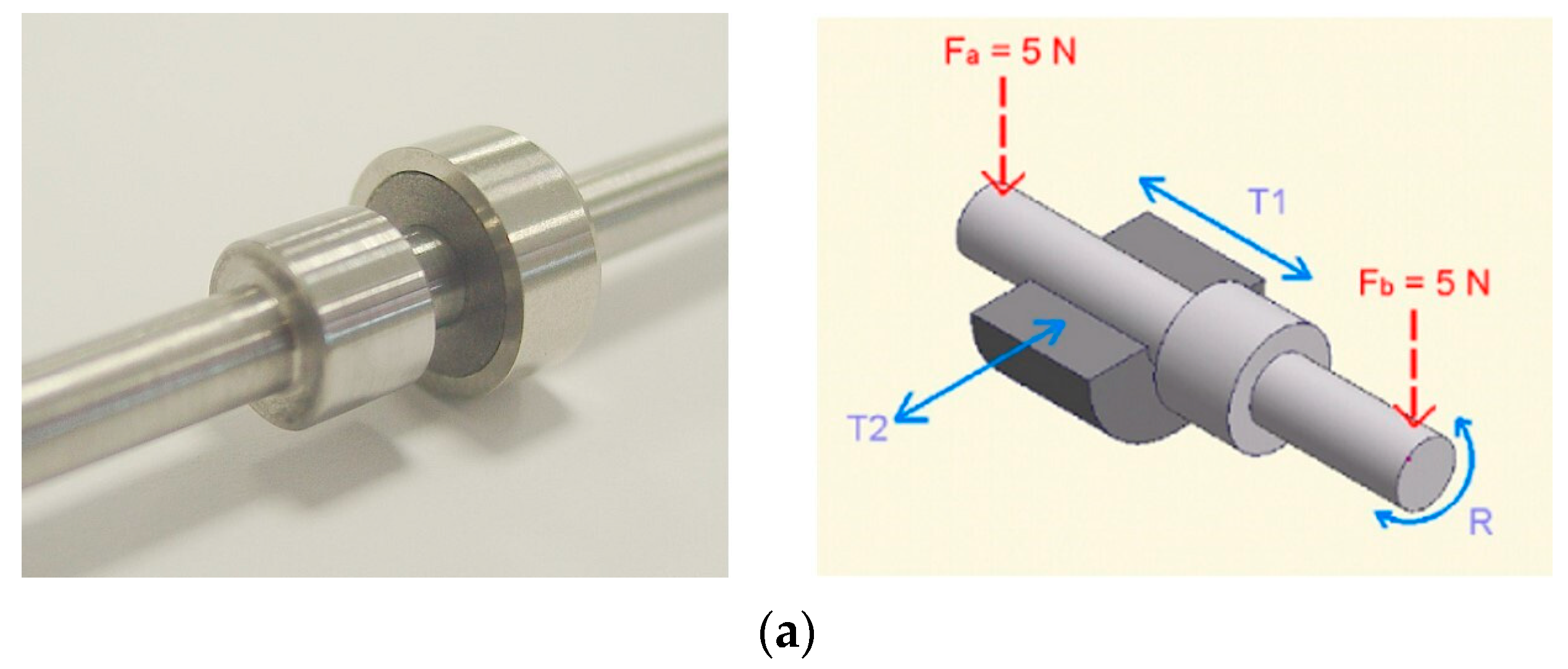
  • A graphite bearing with an internal diameter of 4.02 mm and a length of 8 mm, either impregnated or not with polymer. The mechanical characteristics of the graphite are outlined in Table 1;
  • The shaft, with a diameter of 3.97 mm and a 7 mm diameter stop, which was precision-machined from AISI 304L austenitic stainless steel. It possesses a Young’s Modulus of approximately 190 GPa, and its Vickers Hardness is 180 HV.
The polymer employed for graphite impregnation is polytetrafluoroethylene (C2F4)n, exhibiting a density of ρ = 2200 kg/m3 at ambient temperature and ρ = 2400 kg/m3 at 200 °C. It boasts a melting temperature of approximately 327 °C and offers continuous heat resistance, allowing for its application in high-heat tribological contacts up to 260 °C. Known for its low friction coefficient (µ = 0.02) [10,11] this polymer is commonly used as a non-stick material. The graphite impregnation involves a ratio of about 10% by weight of the polymer. Graphite (G) and polymer-impregnated graphite (GP) materials are manufactured, machined and referenced by Carbone Lorraine. The 10% polymer impregnation rate is a choice made by the manufacturer. Carbone Lorraine markets these materials for high-temperature tribological applications in the aerospace industry.

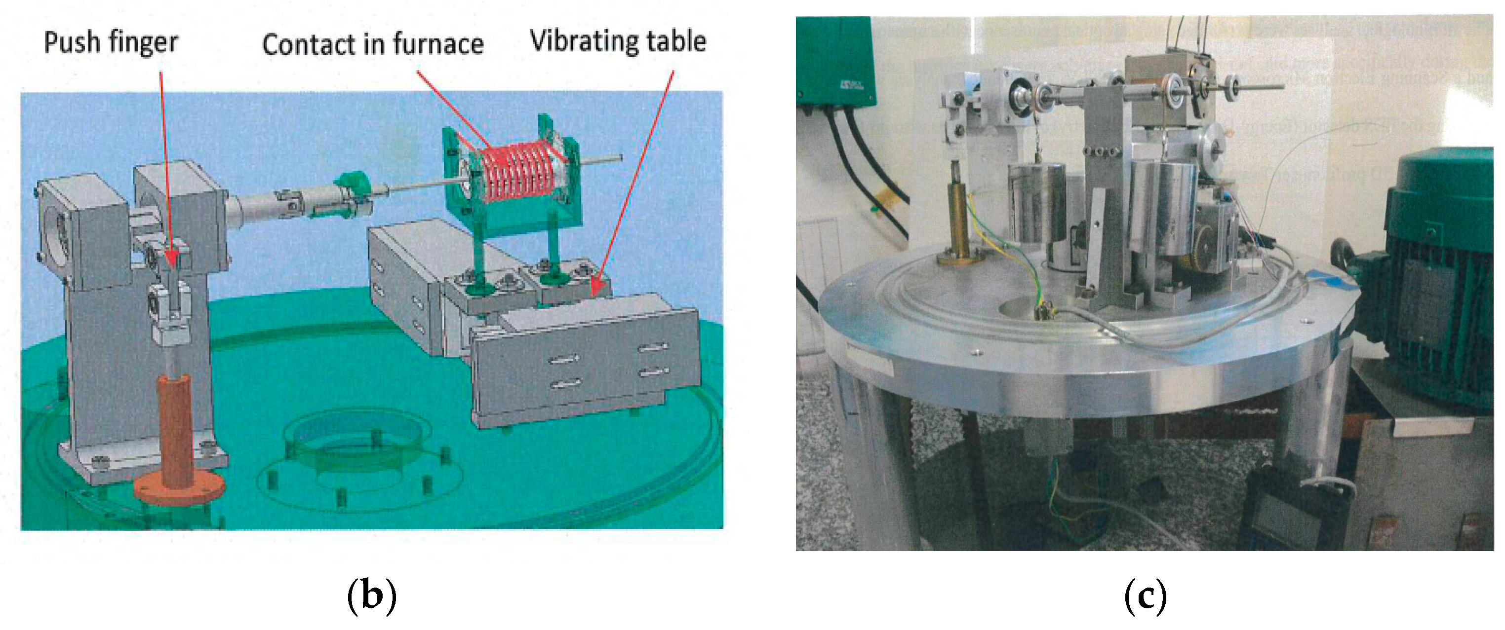
2.2. Experimental Setup

The experimental setup utilized is thoroughly detailed in [22,23]. Figure 1a illustrates the studied contact along with the applied mechanical stresses. Figure 1c shows a general view of the tribometer used.
The shaft/bearing contact was situated within a small furnace (Figure 1b) heated to 500 °C through electrical resistance and subjected to two vibrating stresses, denoted as T1 and T2. The tests were conducted under ambient atmosphere conditions, with the contact temperature maintained at 270 °C. The temperature was measured, monitored and controlled by thermocouples implanted in the bearing. Two distinct relative movements occur at the contact. The shaft underwent a rotary movement (R) with oscillations of ± 1.7° at a frequency of 10 Hz. Simultaneously, the bearing experienced alternating axial (T1) and radial (T2) translational movements at a frequency of 100 Hz.
The amplitude of these movements depends on the clearance, initially set to 50 µm between the graphite and steel stops, and the radial clearance estimated at 15 µm after thermal equilibrium between the shaft and the bearing. A 10 N load was applied through two forces, Fa and Fb, acting respectively at 45 mm and 60 mm from the center of the bearing. This loading induces misalignment within the contact. Two types of tests were conducted:
  • In the first, labeled as “vibration tests”, all mechanical stresses were applied, and the friction torque was measured periodically (over 10 min intervals) at various stages of the tests.
  • In the second, referred to as “vibration-free tests”, the T1 and T2 stresses were not applied, and the friction torque is continuously measured throughout the tests.

3. Results

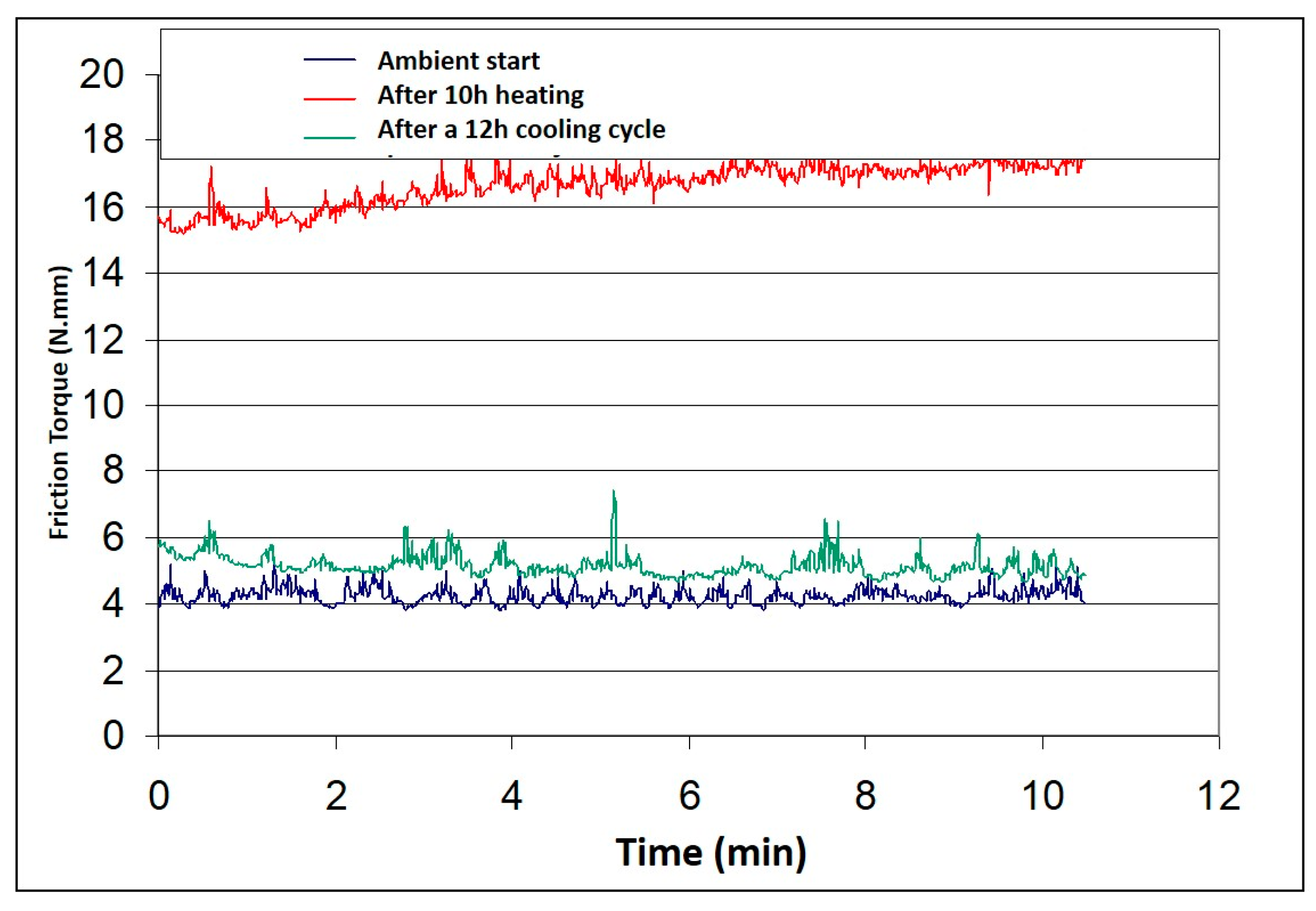
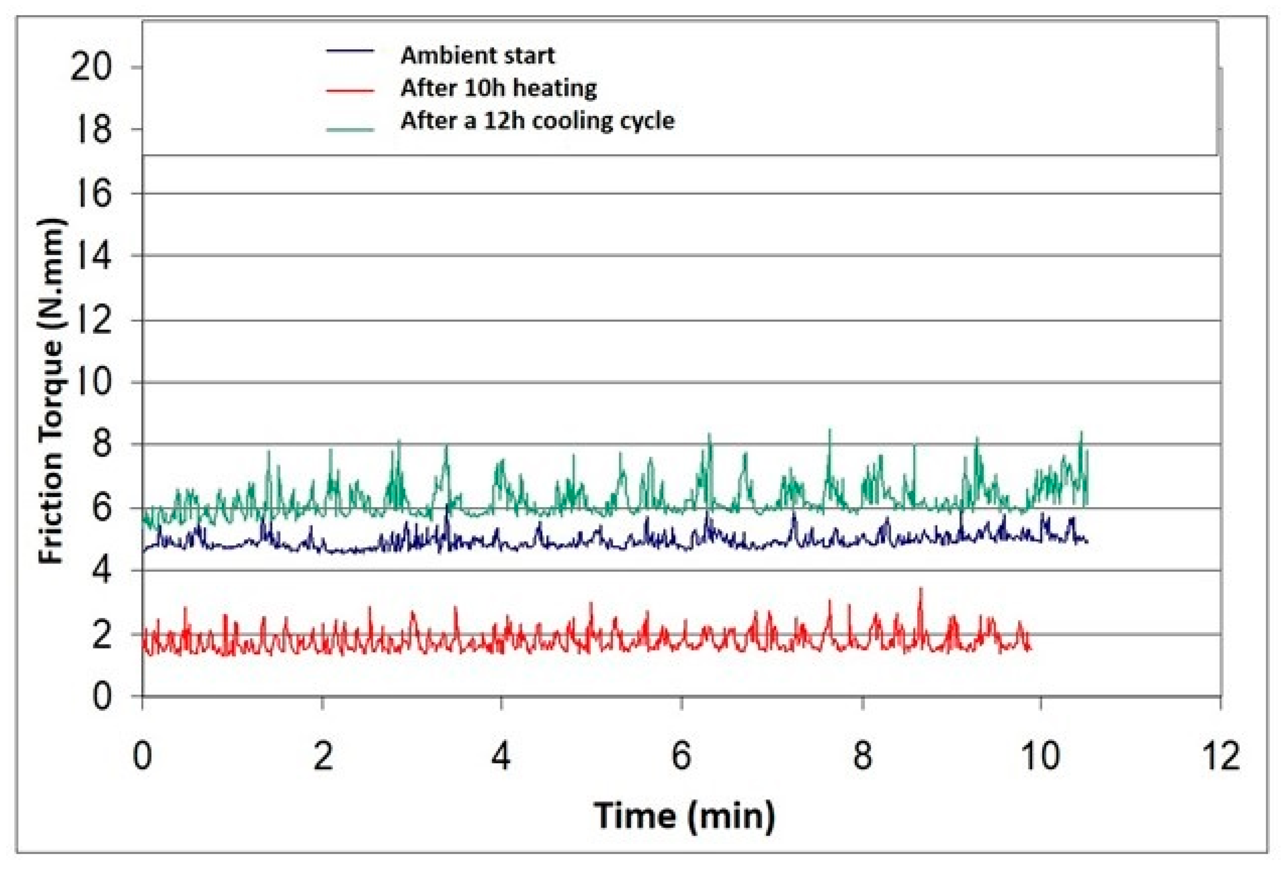
3.1. Vibration Tests: Friction

The friction torques observed in the tribological tests for the pure graphite/stainless steel sample at various temperatures (Figure 2) distinctly illustrate a variation in friction torque. This variation is characterized by a shift from a low friction torque of 5 N·mm to a more severe and higher friction torque of 18 N·mm, occurring above 150 °C. This transition aligns with a change in the friction coefficient, transitioning from a low value of µ = 0.08 to a higher value of µ = 0.3.
In the case of the graphite-impregnated polymer/stainless steel couple, the friction torque observed in tribological tests conducted at varying temperatures (refer to Figure 3) distinctly reveals a reduction from an already low friction torque of 5 N·mm to an exceptionally low value of 2 N·mm above 160 °C. This reduction in friction torque aligns with a transition from a low friction coefficient value of µ = 0.08 to an exceptionally low value of µ = 0.03.
The friction torques are initially comparable at the onset of the tests at room temperature (approximately 5 N·mm), but their trajectories diverge significantly once the high-temperature phase commences. Specifically, the pure graphite/AISI 304L stainless steel couple exhibits a substantial escalation in its friction torque, reaching 18 N·mm at 270 °C. Conversely, the couple comprising polymer-impregnated graphite/steel 304 L experiences a notable reduction in its friction torque, settling at around 2 N·mm under the same conditions.
The substantial increase in friction torque observed with the graphite bearing appears to stem directly from the drying of the contact due to elevated temperatures. Beyond 150 °C, graphite loses its ability to accommodate displacements between surfaces, attributed to the drying of physisorption reservoirs. The introduction of polymer impregnation proves critical in overcoming this drying issue. It not only effectively restricts the escalation of friction torque beyond 150 °C but even diminishes it in comparison to the friction phase at room temperature. During this high-temperature phase, there seems to be a melting of the impregnant, resulting in a “quasi-fluid” lubrication of the contact.

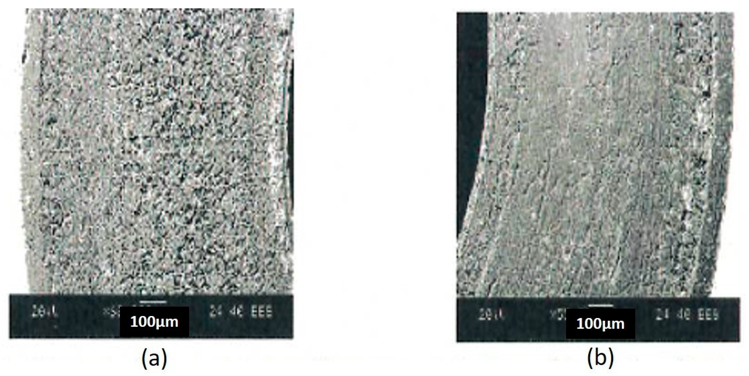
3.2. Vibration Tests: Wear and Damage

Regarding the degradation of the components, two distinct contact zones emerge during these vibration tests:
  • The contact zone between the bearing and the cylindrical bearing surface of the shaft, constituting a permanent contact.
  • The contact zone between the graphite bearing and the metal thrust of the shaft, characterized by non-permanent contact. This area is subjected to fretting impact stresses in conjunction with the rotational movements of the shaft.
Figure 4 illustrates the progression of wear depth on the pure graphite and impregnated graphite bearing thrust after 30 h of testing at a high temperature of 300 °C. These measurements were obtained using a profilometer along the radius of misalignment on the worn track of the thrust. For pure graphite, the wear depth in this zone is substantial, measuring approximately 20 µm. In contrast, when a polymer impregnation is applied to the bearing, the wear depth is negligible (Figure 4).
Figure 5 and Figure 6 depict the appearance of transfer films observed on the cylindrical surfaces of the shafts after 10 h of vibration testing, featuring a graphite bearing and a polymer-impregnated graphite bearing. While the extent of the transfer films remains approximately constant irrespective of the material constituting the bearing (approximately 2.3 mm), the appearance of the deposits differs notably.
After 10 h of testing with a graphite bearing, the deposit exhibits a homogeneous and patinated appearance, with a very low thickness below 0.5 µm. Conversely, the transfer film acquired from testing with a polymer-impregnated graphite bearing displays considerable heterogeneity. It showcases intermittent zones of substantial thickness, forming clusters of material reaching up to 2 µm. This pattern is indicative of the molten polymer’s appearance and the bonding of the two contacting bodies during cooling phases.

3.3. Vibration-Free Testing

To enhance our comprehension of the impact of impregnation on the tribological behavior of graphite concerning temperature variations, supplementary tests without vibration were executed. These tests enabled the measurement of friction torque for both pure graphite (G) and its impregnated counterpart (GP). In each tribological test, we systematically varied the furnace temperature, ranging from ambient temperature to 270 °C, followed by a subsequent decrease to ambient temperature (Figure 7).
The recorded friction torques indicate that the two materials exhibit similar tribological behavior at the beginning and end of the room temperature test. However, as soon as the temperature exceeds 150 °C, the two materials demonstrate divergent tribological behaviors.
The evolution of the friction torque with temperature during these tests has enabled the identification of five distinct friction phases. These phases are extensively described in [24] for a non-impregnated graphite bearing. While they are also present with a polymer-impregnated bearing, their nature is markedly different. Phases 1 and 2, identical to those observed with a non-impregnated bearing, exhibit stable and relatively low friction torque, around 5 N·mm for the first one and a drop of the friction torque during phase 2. However, a clear differentiation becomes apparent from phase 3. In this phase, when the temperature exceeds 150 °C, the two materials behave in opposite ways. The friction torque of pure graphite (G) increases, while that of impregnated graphite decreases towards a state of lubricated friction. In phase 4, when heating is switched off and temperatures are reduced, the friction torque of both materials is low. Phase 5 is conducted at room temperature, as in phase 1 (Figure 7).
To validate this hypothesis, in addition to recording the evolution of the friction torque during the tests, real-time spectral analysis by Fast Fourier Transform (FFT) was performed on the signal obtained from the sensor dedicated to measuring the friction torque. This analysis was conducted on a “window” equivalent to 10 periods of the periodic signal. It ensures that no parasitic frequency interferes with the signal and verifies the “dry” nature of the contact. As illustrated in Figure 8a, during a dry contact, the FFT is characterized by the presence of two characteristic peaks—one at the frequency f corresponding to the oscillation frequency of the shaft (in our case, 10 Hz) and the other at its multiple frequency 3.f = 30 Hz, originating from the stick–slip phenomenon occurring during the change in direction of the rotary oscillation [25]. These characteristic peaks are consistent for all material pairs in this study at both room temperature and high temperature.
Tests conducted with the polymer-impregnated bearings exhibit a distinct behavior during the high-temperature phases, with the disappearance of the second peak at 3f characteristic of dry friction (Figure 8b).

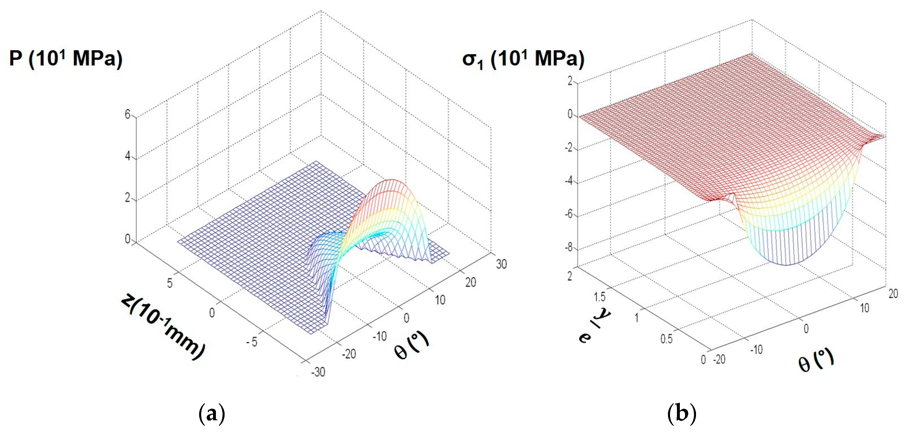
4. Contact Pressure and Stress Fields

To gain a deeper understanding of the tribological phenomena within the contact, a numerical model specifically tailored for the misaligned cylinder/cylinder contact was developed. This adaptation was built upon an existing code created by Djamaï for a contact involving a sphere and a plane [26]. Leveraging fluid lubrication theories to simulate a misaligned shaft/bearing contact, particularly relying on equations for calculating the oil film height (h) within the contact, allowed for the computation of pressure fields and stress fields within the scope of our study:
h θ , z = C + e cos θ φ δ z L 2 C L cos θ β
where
  • θ is the angle defining the angular position of the point where we wish to calculate h.
  • z is the axial position of the point where we wish to calculate h.
  • L is the length of the bearing.
  • C is the radial clearance defined by C = Rbearing − Rshaft.
  • e is the eccentricity in the center plane of the bearing (distance between the center of the bearing O0 and that of the shaft C0).
  • φ is the wedge angle representing the angle between the center line (O0 C0) and the direction of the load N.
  • −δ is the relative misalignment, with = d C   δ, where d is the magnitude of the misalignment characterized by the modulus of the projection of the segment C1C2 in a straight section of the bearing. C1 and C2 are the positions of the shaft center at both ends of the bearing.
  • β is the misalignment angle between the line of centers C1C2 and the direction of load N (Figure 9).
Figure 9. Shaft/bearing contact in YZ plane [26].
Coatings 14 00207 g009
Table 2 compiles the key findings for the phases observed at room temperature at the initiation of the tests, where it is reasonable to assume that the bearings, regardless of their nature, share the same physical state (non-molten polymer impregnant).
The elevated maximum pressure observed with the polymer-impregnated bearing seems to stem from the impregnant filling the porous asperities of the graphite, thereby “stiffening” it.
The configuration of the pressure fields and the distribution of principal stress indicate a significant pressure concentration at the contact’s edge, attributable to the combined effects of misalignment and edge effects (Figure 10).
Figure 10 illustrates the contact pressure distribution obtained via numerical simulation for a non-conformal cylinder-in-cylinder contact pressed together by an applied normal load N = 10 N, with a misalignment of 0.05°.
Considering these findings and noting the maximum stress values calculated on the surface—approximately 65 MPa for a graphite bearing and 69 MPa for a polymer-impregnated graphite bearing—it is evident that the bearings are spared from compression degradation during the tests. These values remain significantly below the compressive strength of the graphite employed in the study.

5. Discussion

5.1. Thrust Behavior Analysis

All tested bearings exhibited imprints characterized by variable depth and width, comprising numerous concentric severe scratches. The asymmetry in this degradation can be attributed to misalignment. Additionally, due to edge effects, the highest stress levels occurred in the opposite zone of the external diameter of the shaft thrust. This explains why degradations consistently propagate from this area. Furthermore, the contact between the two thrusts is not continuous, and the wear is instigated by impact fretting. This is accentuated by the rotary motion of the shaft and the material packing induced by impacts.
Figure 11a,b present the morphology aspect of wear observed on the unimpregnated and impregnated graphite thrust for a long duration. The thrust from pure graphite (Figure 11a) is deeply worn and presents a rough and porous aspect. However, the impregnated graphite (Figure 11b) is only slightly worn, with a smooth thin film.
The temporal evolution of thrust morphology varies depending on the material (Figure 4, Figure 5 and Figure 6). In the case of graphite material (G), the wear zone expands to the entire contact area, leading to a significant increase in axial clearance, preventing the correct operation of the mechanism. Conversely, for material (GP), the initial degradation occurs later and is more superficial, with smaller dimensions and remaining localized to one side of the bearing. The reduced wear in this case can be attributed to better mechanical properties, specifically compressive and tensile strengths higher than those of material (G).
When compared with reference surfaces, the bearings tested on the experimental apparatus exhibit a smaller maximum print depth, with a ratio of 3 for similar operation durations. Two factors could contribute to this difference: the lower acceleration level of the axial and radial reciprocating motions in the test rig or the initial surface condition of the thrusts for the shaft and the bearing, as the reference surfaces had a higher roughness with rectification scratches on the metallic thrust.

5.2. Bore Behavior Analysis

The morphological analysis conducted on the bearing bores tested with materials (G) and (GP) reveals that the transfer phenomenon of the bearing towards the shaft is their only common characteristic.
In the case of bearings with material (G), the counterface (Figure 5) presents a uniform film located in the contact zone. The morphology of this film undergoes minimal evolution in tests lasting longer than four hours. This exceptionally thin transfer film, challenging to quantify with a profilometer, resembles a “patina”. The thinness is likely attributed to the lamellar structure of the graphite, where weak Van der Waals bonds between the basal planes facilitate their cleavage.
Regarding the bearing bore with material (G), the observation of perpendicular scratches, followed by their disappearance after six hours, suggests the establishment of a balance within the contact. The third body generated in the initial hours of testing adheres to the first two bodies, resulting in a glazing of the contact surfaces. Consequently, the initial material couple (stainless steel/graphite) is replaced by a graphite/graphite friction pair, generating a low coefficient of friction at low temperature.
Differences observed with the industrial mechanism employing the same bearings can be attributed to the consistency of the relative movements applied in the experimental apparatus. Any variation in these parameters could disrupt the established balance and induce consumption of the third body (as proposed by Delgado et al. [25]).
The rubbed surface of the shaft in the (GP) bearings exhibits a coating (Figure 6) whose morphology and composition undergo significant changes between four and fifteen hours of testing. It gradually becomes surrounded and covered by polymer. After fifteen hours, the transfer film becomes thick. The contact zones of both the shaft and the bearing are predominantly covered with polymer. Consequently, the initial material couple (stainless steel/impregnated carbon) is substituted by a friction polymer/polymer pair, leading to a very low friction coefficient.
The reference surfaces of the industrial mechanisms employing material (GP) exhibit a lower concentration of polymer in the contact zone. Subsequent tests on the testing apparatus revealed that the temperature was the determining factor behind this difference. Specifically, the reference bearings had operated at 220 °C, which is 50 °C below their normal operating temperature.

5.3. Influence of the Temperature on the Impregnated Graphite Behavior

Our tribological tests conducted at high temperature (270 °C) revealed a substantial friction torque of 18 N·mm for pure graphite (Figure 2 and Figure 7) and an exceptionally low friction torque of 2 N·mm for impregnated graphite (Figure 3 and Figure 7). These values correspond, respectively, to a high coefficient of friction (µ = 0.6) and to a low coefficient of friction (µ = 0.02), akin to the friction torque of a hydrodynamic bearing.
Moreover, the spectral analysis of the fretting friction signal exhibits the first peak at the frequency f of the periodic fretting signal and a second peak at the frequency 3.f. This frequency signature indicates a hydrodynamic shaft/bearing oscillation, implying liquid-lubricated friction above 270 °C (Figure 8). Additionally, visualization of the wear tracks of impregnated graphite (Figure 6) reveals the accumulation of polymer plates on the surfaces [27,28,29,30,31].
The friction tests were consistently conducted at the operational temperature of T = 270 °C, aligning with the working conditions in the industrial mechanism. The primary objective of this study is not to investigate the impact of temperature variations on the friction and wear behavior of materials (G) and (GP). However, the effect of applied temperature on the behavior of impregnated graphite (GP) became evident through the observation of polymer agglomeration on the highly compressed sliding contact surface of the bearing.
As depicted in Figure 8, within the highly compressed zone of the misaligned contact, the transition unfolds from the initial impregnated graphite surface with a large specific volume υi to the eventual pure polymer surface with a smaller specific volume υf. This transition occurs through a diffusion process of the polymer from the material’s bulk to the surface, driven by the contact temperature and the contact pressure P, according to Le Chatellier’s principle.
The specific volume of impregnated graphite is higher than that of pure polymer. This discrepancy results in a reduction in the phase transition temperature as the Hertzian contact pressure increases, following Clapeyron’s Law [22].
d T d P = T v f v i   L
where L is the transition phase energy of polymer (L = 1.1 × 10³ J.kg−1), the impregnated graphite specific volume, depending on the polymer amount incorporated in the graphite and the polymer specific volume. υi = 5.5 × 10⁻⁴ m3·kg−1 is greater than υf = 4.5 × 10⁻⁴ m3·kg−1, then (υf- = υi) < 0; thus, the transition temperature T decreases as the contact pressure P increases dT/dP < 0. The pressed contact transits to the densest phase at low temperature according to Le Chatelier’s law of moderation.
The critical temperature T of phase transition at the pressure P is given by the following equation:
T = T m e x p ( v f v i P   L )
where Tm is the melting temperature of polymer: Tm = 327 °C.
The exponential factor depends on the gradient pressure
Δ P = P H P 0 P H
where P0 is the atmospheric pressure and PH is the cylinder-in-cylinder contact pressure.
For normal Hertzian contact without misalignment, the contact pressure is given by:
P H = L n E e q π R 1 / 2
where Ln is the normal load by unit of length, R is the equivalent contact radii 1 R = 1 R 1 1 R 2 and Eeq is the equivalent Young’s modulus for the contact.
Here, Eeq = 11.45 GPa and ∆R = R2 − R1= 0.02 mm; thus:
R C = R 0 2 R = 200   m m
For an applied normal load of 10 N on bearing with 4 mm in length, L n = 10 4 = 2.5   N · m m 1 , and thus:
The gradient pressure ∆P = 2Ln/πa = 6 MPa is lowered to produce a significant decrease in the phase transition temperature of the material as calculated in Equation (3).
However, in the case of misaligned and rough contacts, the contact pressure is high, as calculated through a modification of the numerical simulation developed by Andel. Djamaï [26].
For a smooth contact surface area with a misalignment of 0.05°, the maximum pressure 63 MPa obtained by a numerical simulation for material (GP) induces a large reduction in the melting temperature in the contact.
For a normal load of N = 10 N and an oscillating frequency of f = 10 Hz, we have computed the temperature of the contact asperities induced by fretting to be approximately 50 °C. This temperature, reached in the contact asperities, is insufficient to induce polymer fusion.
The experimental results reveal a significant distinction between the two material pairs under investigation: graphite/stainless steel and graphite-impregnated polymer/stainless steel. Pure graphite loses its tribological properties above 150 °C, while PTFE polymer-impregnated graphite maintains its tribological properties, including a low coefficient of friction, up to 270 °C. Beyond 150 °C, the impregnating polymer melts in the contact zone, leading to hydrodynamic lubrication-type friction with a low friction torque.
Tribological tests conducted at high temperature (270 °C) resulted in a high friction torque of 18 N·mm and a high wear rate in bearing thrust for the pure graphite/stainless steel couple. In contrast, the impregnated graphite/stainless steel couple exhibited a very low friction torque of 2 N·mm and a low wear rate (Dw). This low value is comparable to the friction torque of a hydrodynamic bearing.

6. Conclusions

This experimental tribological study, conducted at high temperature (270 °C) to compare the fretting behavior of pure graphite and polymer-impregnated graphite, reveals the following findings:
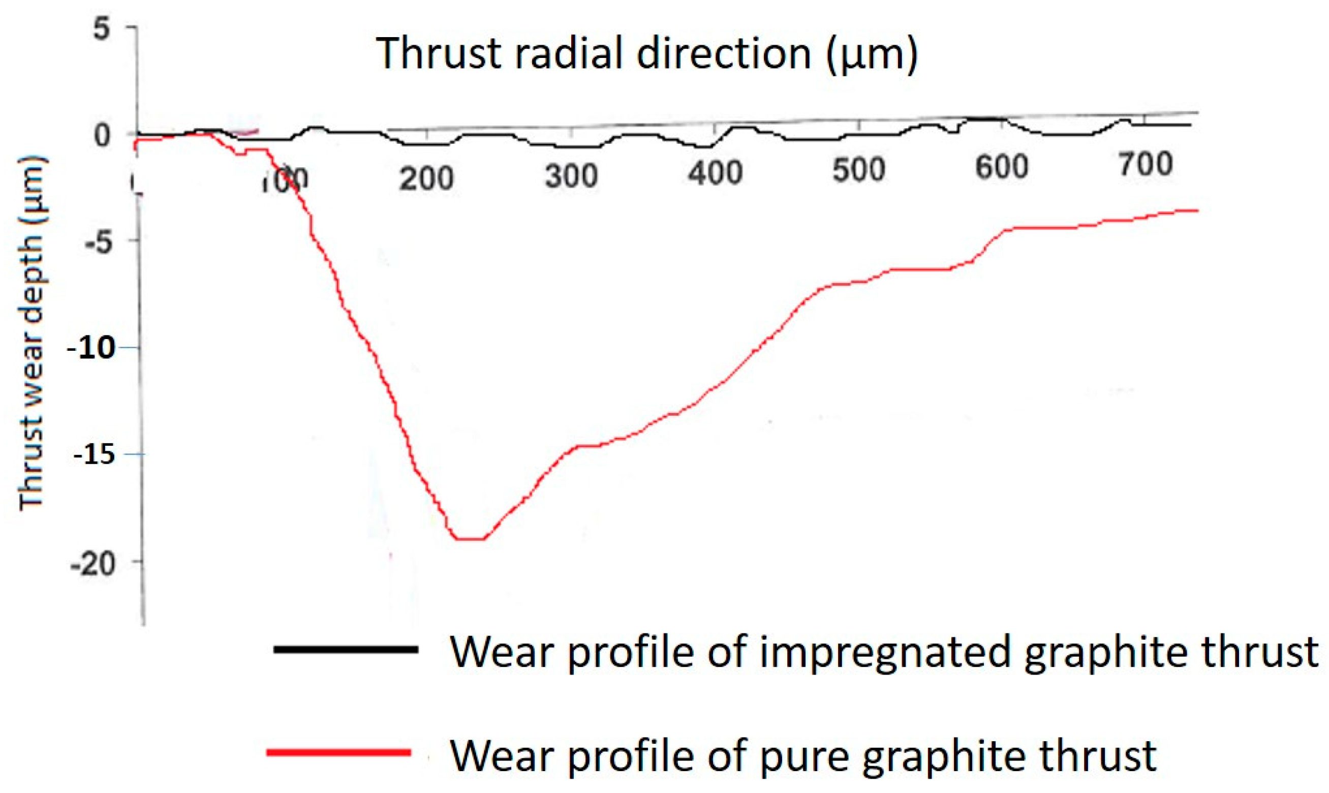
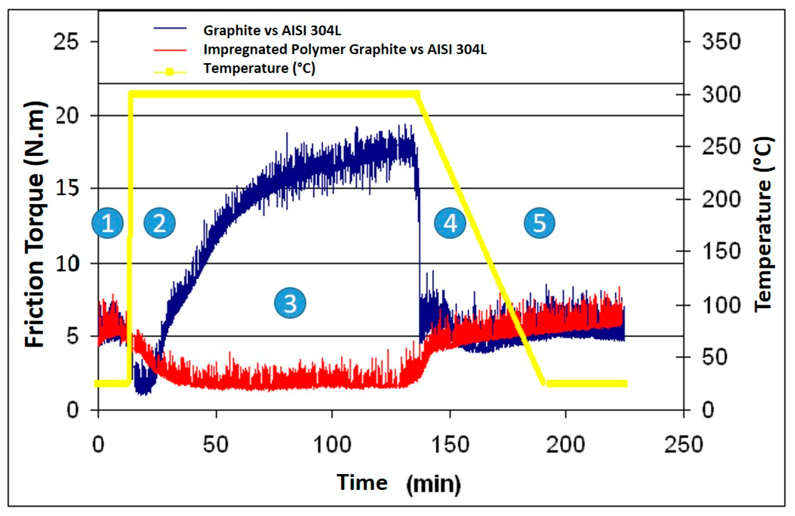
  • At room temperature and up to 150 °C, both materials exhibit identical tribological behavior. The frictional torque resistance is approximately 5 N·mm, and the bearing wear profiles are similar.
  • However, at elevated temperatures above 150 °C, the frictional torque of pure graphite increases by more than threefold, and the wear profile of the thrust bearing becomes almost 100 times deeper than that measured at room temperature. In contrast, the friction torque of polymer-impregnated graphite is halved, and the wear profile of the thrust bearing remains comparable to that measured at ambient temperature.
  • Under contact pressure, the melting temperature of the polymer decreases, initiating polymer diffusion through the graphite porosity to the contact zone starting from 150 °C. The formation of a thin fluid film of polymer on the asperities of the contact lubricates the interface, resulting in a friction torque that is half that of ball bearings, as the Teflon film exhibits anti-adhesive properties.
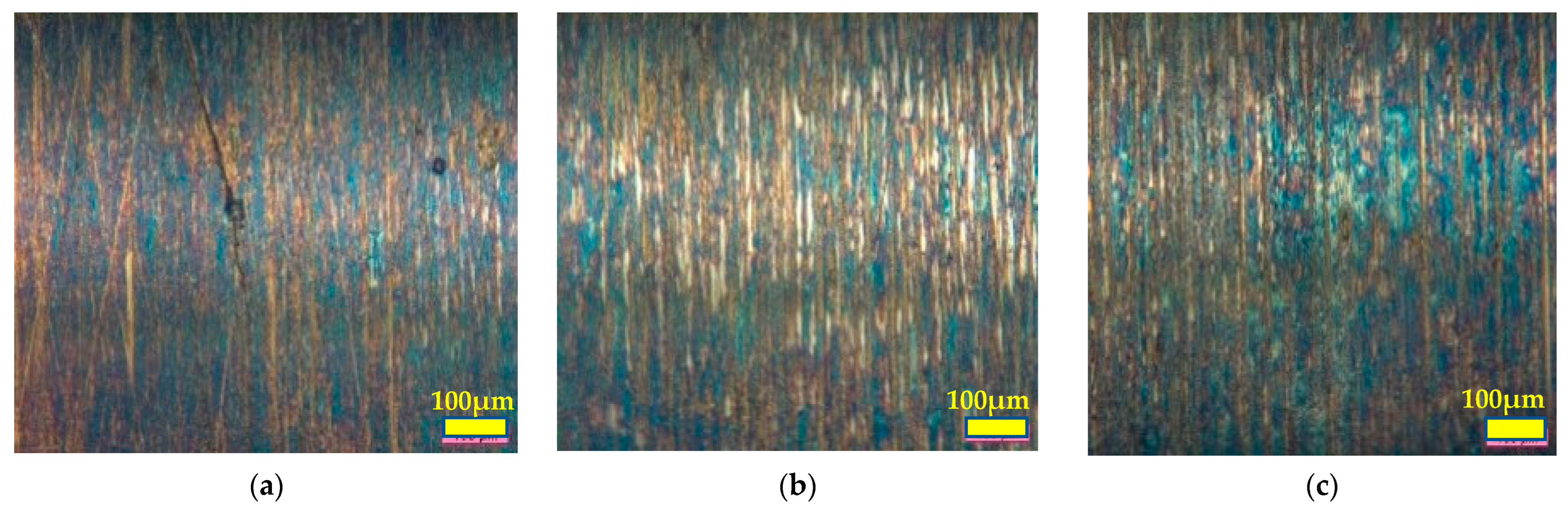
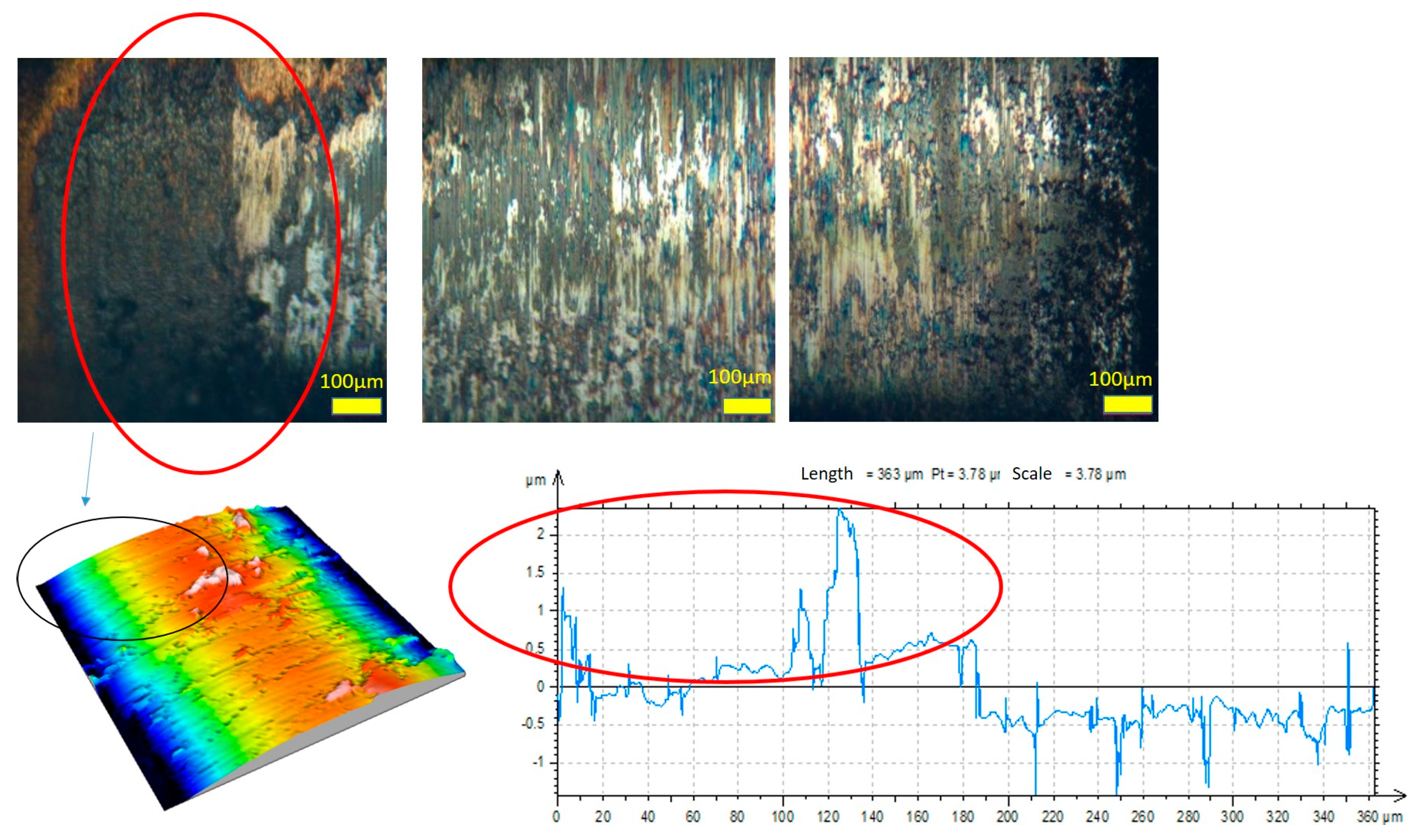
  • The spectral analysis of the fretting friction signal displays the first peak at frequency f of the periodic fretting signal and a second peak at frequency 3.f. This frequency signature indicates a hydrodynamic shaft/bearing oscillation, revealing liquid-lubricated friction above 270 °C. Additionally, optical visualization of the impregnated graphite wear tracks illustrates the accumulation of polymer plates on the surfaces.

Author Contributions

Conceptualization, H.Z.; methodology, S.T. and L.D.; software, S.T.; investigation, M.A.; writing—original draft preparation, H.Z. and C.R.; writing—review and editing, C.R. and K.B.; visualization, K.B.; supervision, H.Z.; project administration, H.Z.; funding acquisition, H.Z. All authors have read and agreed to the published version of the manuscript.

Funding

This research received no external funding.

Institutional Review Board Statement

Not applicable.

Informed Consent Statement

Not applicable.

Data Availability Statement

Data are contained within the article.

Conflicts of Interest

The authors declare no conflicts of interest.

References

  1. Ramadanoff, D.; Glass, S.W. High-altitude brush problems. Trans. AIEE 1944, 63, 825–829. [Google Scholar]
  2. Savage, R.H. Graphite lubrication. J. Appl. Physic 1948, 19, 1–10. [Google Scholar] [CrossRef]
  3. Xue, X.; Jia, J.; Huo, Q.; Jia, J. Experimental investigation and prediction method of fretting wear in rack-plane spline couplings. Proc. Inst. Mech. Eng. Part J J. Eng. Tribol. 2020, 235, 1025–1037. [Google Scholar] [CrossRef]
  4. Zaidi, H.; Lepage, J. Influence de l’eau sur le comportement tribologique de matériaux carbonés. J. De Chim. Phys. 1987, 84, 325–329. [Google Scholar] [CrossRef]
  5. Zaidi, H.; Néry, H.; Paulmier, D. Stability of lubricating properties of graphite by orientation of the crystallites in the presence of water vapour. Appl. Surf. Sci. 1993, 70–71, 180–185. [Google Scholar] [CrossRef]
  6. Lancaster, J.K. Transitions in the friction and wear of carbons and graphites sliding against themselves. ASLE Trans. 1975, 18, 187–201. [Google Scholar] [CrossRef]
  7. Spreaborough, J. The frictional behaviour of graphite. Wear 1962, 5, 18–30. [Google Scholar] [CrossRef]
  8. Zhang, X.-Y.; Cai, Z.-B.; Peng, J.-F.; Liu, J.-H.; Du, R.; Ren, P.-D. Experimental study of the fretting wear behavior of Inconel 690 alloy under alternating load conditions. Proc. Inst. Mech. Eng. Part J J. Eng. Tribol. 2018, 232, 1343–1351. [Google Scholar] [CrossRef]
  9. Bhaskar, S.V.; Kudal, H.N. Tribology of nitrided-coated steel-a review. Arch. Mech. Technol. Mater. 2017, 37, 50–57. [Google Scholar] [CrossRef]
  10. Burris, D.L.; Sawyer, W.G. A low friction and ultra-low wear rate PEEK/PTFE composite. Wear 2006, 261, 410–418. [Google Scholar] [CrossRef]
  11. Ullah, S.; Haque, F.M.; Sidebottom, M.A. Maintaining low friction coefficient and ultralow wear in metallic filled PTFE composites. Wear 2022, 498–499, 204338. [Google Scholar] [CrossRef]
  12. Chang, Y.Y.; Amrutwar, S. Effect of Plasma Nitriding Pretreatment on the Mechanical Properties of AlCrSiN-Coated Tool Steels. Materials 2019, 12, 795. [Google Scholar] [CrossRef]
  13. Soto, J.; Jada, M.; Guyenro, N.; Delaunay, D. Thermal cycling aging of encapsulated phase change material—Compressed expanded natural graphite composite. Therm. Sci. Eng. Prog. 2021, 22, 100836. [Google Scholar] [CrossRef]
  14. Kim, Y.U.; Park, J.H.; Beom, Y.Y.; Sungwoong, Y.; Seunghwan, W.; Kim, S. Mechanical and thermal properties of artificial stone finishing materials mixed with PCM impregnated lightweight aggregate and carbon material. Constr. Build. Mater. 2021, 272, 121882. [Google Scholar] [CrossRef]
  15. Lu, F.; Liu, J. Experimental and numerical investigation on wear behavior of carbonfiber-reinforced carbon matrix composite used in rotary gas seals. Proc. Inst. Mech. Eng. Part J J. Eng. Tribol. 2020, 235, 575–587. [Google Scholar] [CrossRef]
  16. Amirat, M.; Zaidi, H.; Beloufa, A. Friction in vacuum and under different gaseous environment of magnetized sliding ferromagnetic contact. Proc. Inst. Mech. Eng. Part J J. Eng. Tribol. 2021, 235, 18–32. [Google Scholar] [CrossRef]
  17. Coscia, U.; Longo, A.; Palomba, M.; Sorrentino, A.; Barucca, G.; Di Bartolomeo, A.; Urban, F.; Ambrosone, G.; Carotenuto, G. Influence of the thermomechanical characteristics of low-density polyethylene substrates on the thermoresistive properties of graphite nanoplatelet coatings. Coatings 2021, 11, 332. [Google Scholar] [CrossRef]
  18. Khare, H.S.; Burris, D.L. The effects of environmental water and oxygen on the temperature-dependent friction of sputtered molybdenum disulfide. Tribol. Lett. 2013, 52, 485–493. [Google Scholar] [CrossRef]
  19. Zhu, Z.; Bai, S.; Wu, J.; Xu, L.; Li, T.; Ren, Y.; Liu, C. Friction and wear behavior of resin/graphite composite under dry sliding. J. Mater. Sci. Technol. 2015, 31, 325–330. [Google Scholar] [CrossRef]
  20. Xin, L.; Yang, B.B.; Li, J. Wear damage of Alloy 690TT in partial and gross slip fretting regimes at high temperature. Wear 2017, 390, 71–79. [Google Scholar] [CrossRef]
  21. Hojjati-Talemi, R.; Wahab, M.A.; Baets, P.D. Finite element simulation of phase difference effects on fretting fatigue crack nucleation behavior. Proc. Inst. Mech. Eng. Part J J. Eng. Tribol 2014, 228, 470–479. [Google Scholar] [CrossRef]
  22. Doyen, F.; Zaidi, H.; Rivière, J.P.; Leclercq, B.; Rocchi, J. Fretting contact study of stainless steel/graphite in a dry shaft/bearing contact with thrust. Wear 2007, 263, 508–517. [Google Scholar] [CrossRef]
  23. Zaidi, H.; Amirat, M.; Beloufa, A. Fretting study of an impregnated graphite bearing/nitrided s. steel in a dry contact submitted to severe thermo-vibratory loading. Proc. Inst. Mech. Eng. Part J J. Eng. Tribol. 2022, 236, 1707–1717. [Google Scholar] [CrossRef]
  24. Sylvestre, M.; Zaidi, H.; Rivière, J.P.; Eyidi, D.; Doyen, F. Fretting contact study of Ti-6Al-4 V/graphite couples in a dry shaft/bearing contact with thrust: Influence of plasma nitriding of the titanium alloy. Surf. Coat. Technol. 2010, 205, 1374–1380. [Google Scholar] [CrossRef]
  25. Delgado, A.; San Andrès, L. Identification of structural stiffness and damping coefficients of a shoes brush seals. In Proceedings of the ASME 2005 International Design Engineering Technical Conferences and Computers and Information in Engineering Conference, Long Beach, CA, USA, 24–28 September 2005; pp. 1–6. [Google Scholar]
  26. Djamai, A. Modélisation Tridimensionnelle et Etude du Rayage des Revêtements Fragiles: Identification des Endommagements par Résolution du Problème du Contact et du Champ des Contraintes. Ph.D. Thesis, Université de Poitiers, Poitiers, France, 2005. [Google Scholar]
  27. Arnaud, P.; Fouvry, S.; Garcin, S. Fretting wear rate impact on Ti-6Al-4V fretting crack risk: Experimental and numerical comparison between cylinder/plane and punch/plane contact geometries. Tribol. Int. 2016, 108, 32–47. [Google Scholar] [CrossRef]
  28. Sline, H.E. Solid lubricant materials for high temperatures—A review. Tribol. Int. 1982, 15, 303–315. [Google Scholar] [CrossRef]
  29. Allam, I.M. Solid lubricants for applications at elevated temperatures. J. Mater. Sci. 1991, 26, 3977–3984. [Google Scholar] [CrossRef]
  30. Prateek, M.; Mani, K.P.; Kishor, K.S.; Pallav, G. Structural, wear and thermal behavior of Cu–Al2O3–graphite hybrid metal matrix composites. Proc. Inst. Mech. Eng. Part L J. Mater. Des. Appl. 2020, 234, 1154–1164. [Google Scholar]
  31. Li, L.; Kang, L.; Ma, S.; Li, Z.; Ruan, X.; Cai, A. Finite element analysis of fretting wear considering variable coefficient of friction. Proc. Inst. Mech. Eng. Part J J. Eng. Tribol 2018, 233, 758–768. [Google Scholar] [CrossRef]
Figure 1. Contact geometry: (a) cylinder-in-cylinder contact (shaft/bearing with thrust), (b) vibration application to the furnace and push finger for shaft rotation, (c) general view of the tribometer.
Coatings 14 00207 g001aCoatings 14 00207 g001b
Figure 2. Friction torques measured throughout the vibration tests at different temperatures for the couple pure graphite/stainless steel.
Coatings 14 00207 g002
Figure 3. Friction torques measured throughout the vibration tests at different temperatures for the impregnated graphite/stainless steel couple.
Coatings 14 00207 g003
Figure 4. Radial evolution of bearing thrust wear depth.
Coatings 14 00207 g004
Figure 5. (ac) Transfer film recorded on cylindrical shaft bearing surface after 10 h of thermo-vibratory stresses against a graphite bearing.
Coatings 14 00207 g005
Figure 6. Transfer film recorded on cylindrical shaft bearing surface after 10 h of thermo-vibratory stresses against a polymer-impregnated graphite bearing. Red and black oval shapes show the area observed.
Coatings 14 00207 g006
Figure 7. Evolution of friction torques as a function of temperature during the two-hour tests without vibrations (T1 and T2). 1 to 5: Transition phases during heating and cooling.
Coatings 14 00207 g007
Figure 8. Spectral analysis of the friction torque versus time curves for 10 periods of rotary oscillation of the shaft during the test phases at 300 °C: (a) graphite bearing/AISI 304L stainless steel shaft, (b) polymer-impregnated graphite bearing/AISI 304L stainless steel shaft.
Coatings 14 00207 g008
Figure 10. Mechanics of contact: (a) pressure fields P(θ’, z) for 0.05° misaligned graphite bearing/steel shaft contact, (b) maximum principal stress distribution σ1 for 0.05° misaligned graphite bearing/steel shaft contact.
Coatings 14 00207 g010
Figure 11. Wear surface morphologies: (a) SEM image of the worn pure graphite thrust surface, (b) SEM image of the worn impregnated graphite thrust surface.
Coatings 14 00207 g011
Table 1. Main mechanical characteristics of graphite and polymer.
PropertyGraphitePTFE (C2F4)nImpregnation of Graphite at 10%
Density (g·cm−3)1,82.21.84
Young’s Modulus (GPa)12211
Shore Hardness763074
Table 2. Stresses in the bearing.
Maximum Pressure for 0.05° Misalignment
(MPa)
Maximum Von Mises Stress at Contact Edge
(MPa)
Maximum Main Surface Stress
(MPa)
Graphite/AISI 304 SS551865
Polymer-impregnated graphite/ AISI 304 SS632269
Disclaimer/Publisher’s Note: The statements, opinions and data contained in all publications are solely those of the individual author(s) and contributor(s) and not of MDPI and/or the editor(s). MDPI and/or the editor(s) disclaim responsibility for any injury to people or property resulting from any ideas, methods, instructions or products referred to in the content.

