Article

Influence of Processing Parameters on Microstructure and Surface Hardness of Hypereutectic Al-Si-Fe-Mg Alloy via Friction Stir Processing

1
Department of Electromechanical Engineering, University of Macau, Macao 999078, China
2
School of Mechanical and Automotive Engineering, South China University of Technology, Guangzhou 510000, China
3
Institute for Development and Quality, Macao 999078, China
*
Author to whom correspondence should be addressed.
Coatings 2024, 14(2), 222; https://doi.org/10.3390/coatings14020222
Submission received: 17 January 2024 / Revised: 6 February 2024 / Accepted: 10 February 2024 / Published: 12 February 2024
(This article belongs to the Section Surface Characterization, Deposition and Modification)

Abstract

:
In this study, the effects of friction stir processing (FSP) parameters on the microstructure and hardness of cast Al-Si-Fe-Mg alloy were investigated. Orthogonal arrays were applied in the design of the experiments. The selected parameters for the experiments included rotation speed, transverse speed, penetration depth, and tilt angle. The microstructure and hardness of the FSPed Al-Si-Fe-Mg were studied using optical and scanning electron microscopy, and microhardness testing, respectively. The quadratic model was proposed to fit the experimental data of hardness. Signal-to-noise ratio (S/N) analysis showed the maximum hardness achieved when rotation speed, transverse speed, penetration depth, and tilt angle were chosen as 1600 rpm, 400 mm/min, 0.1 mm, and 1.5°, respectively. Taguchi’s analysis of variance (ANOVA) was used to determine the significant FSP parameters on hardness, which revealed that rotation speed was the most dominant processing parameter, followed by transverse speed, tilt angle, and penetration depth. Moreover, a quadratic polynomial model was developed to predict and optimize the combination of the parameters, enabling superior mechanical properties. Subsequently, the verification of the microstructure was conducted, demonstrating good agreement between the experimental observation of the microstructure and estimated outcomes.

1. Introduction

Al-Si alloys are extensively used in the aerospace, automotive, and defense industries owing to their exceptional attributes, including lightweight, remarkable strength, high thermal conductivity, low coefficient of thermal expansion, and outstanding wear resistance [1]. Due to the existence of Si, the Al-Si alloys possess lower thermal expansivity, higher fluidity, and better castability compared to other aluminum alloys [2,3]. Hence, hypereutectic Al-Si alloys (14 to 25 wt% Si) are used in high-performance automobile engine parts, such as connecting rods, rocker arms, cylinder sleeves, and piston rings [4,5]. However, traditional cast Al-Si alloys often suffer from mold sticking, shrinkage cavity, and porosity during production. To mitigate the problem of mold sticking, it is customary to incorporate approximately 0.6 to 1 wt% Fe into the Al-Si alloys [6]. While the addition of Mg can improve the strength of the Al-Si alloys, dissolution of Mg in the α-Al matrix induces lattice distortion resulting in solid solution strengthening. In addition, Mg and Si form the Mg2Si phase, which is a reinforcement for enhancing the strength [7]. However, with the increase in Si content, the microstructure of the cast Al-Si alloys consists of coarser and segregated primary Sicrystals, needle-like eutectic Si, and coarse and lathy Fe-rich phase, which greatly deteriorate the continuity of the aluminum matrix [4]. When a load is applied, stress concentration is very likely to occur, potentially serving as initiation points for cracking and severely reducing the mechanical properties.
Therefore, modification and refinement of the Si phase in the Al-Si alloys is of great significance for improving their mechanical properties and expanding their engineering applications. Deformation [8,9], heat treatment [10,11], and the addition of modifiers [12,13] can achieve different degrees of refinement in the Si particles. Among these methods, deformation processes can exhibit a more significant refinement in the Si particles. Furthermore, through the implementation of thermomechanical processing, it is possible to refine the grain structure and introduce dislocations in the Al matrix, consequently enhancing the mechanical strength of the Al-Si alloys [14]. Severe plastic deformation (SPD), which exhibits a greater degree of deformation than conventional plastic deformation, is widely used to refine the grain size and enhance the strength of the Al alloys [15,16,17]. Friction stir processing (FSP) is one of the important SPD methods. Meenia et al. [18] demonstrated that successive FSP passes resulted in the refinement of both Si particles and Al grains, culminating in the cast LM25 aluminum alloy attaining its peak strength and ductility after three FSP passes, measured at 201 MPa and 36.5%, respectively. Saini et al. [19] evaluated the effect of FSP parameters to enhance the mechanical properties of the cast Al-17%Si alloy. With the optimal parameters, due to the refinement of eutectic and primary Si particles, the ultimate tensile stress of the FSPed specimens was improved by 1.26 to 1.35 times, and the percent elongation was increased from less than 2% to 9%. Ma et al. [20] found that ultrasonic-assisted FSP improved the grain-refinement level of A356 casting Al alloys, i.e., reduction in grain size and increase in uniformity of grain distribution leading to enhanced hardness, tensile strength, and percent elongation. Basak et al. [21] used FSP to prepare Al 5086-based surface composites, which introduced severe plastic deformation and made graphene and silicon carbide nano-particulates evenly distributed and ensured grain refinement (from 4.19 to 1.59 μm).
In FSP, the factors affecting microstructure and properties include processing parameters, tool design, materials, and fixture design [22], among which processing parameters such as rotation speed, transverse speed, axial force, tilt angle, and penetration depth are particularly critical. In order to understand the effect of the processing parameters on microstructure and properties of materials, the Taguchi design method and the response surface methodology (RSM) are often used and as efficient ways to identify the most significant factors and optimize the processing parameters via fewer experiments. Premnath et al. [23] indicated that number of passes was the vital parameter for increasing the tensile strength whereas rotation speed is the vital parameter for improving the hardness of the Al-SiC nanocomposites. Ahmadkhaniha et al. [24] found that tilt angle and rotation speed as well as transverse speed are the significant influential parameters for the hardness of the FSPed pure Mg by using Taguchi experimental design and analysis of variance (ANOVA). Butola et al. [25] applied Taguchi technique to fabricate AA7075 matrix surface composites and determine the optimal values of tool rotation speed, tool profile, and reinforcement in FSP. The result showed that rotation speed was the most influential parameter followed by the type of reinforcement and tool profile [25]. Liu et al. [26] used response surface methodology (RSM) to optimize and prepare a new type of AA5083/(SiC-Gr) hybrid surface composite, and establish a mathematical model between input process parameters and wear properties. To predict the output characteristics of the prepared hybrid composites, the error of the prediction results was within ±10%.
Although some researchers have used the Taguchi technique to optimize and analyze the FSP parameters for various materials, no reports have been published regarding the optimization of FSP parameters for the hypereutectic Al-Si-Fe-Mg alloy using the Taguchi method and mathematical model. Consequently, the main objective of this study was to identify the optimal combination of FSP parameters for Al-Si-Fe-Mg alloys, such as rotation speed, transverse speed, penetration depth, and tilt angle for achieving fine and evenly distributed Si particles and optimal surface properties. Mean value analysis (MVA) and analysis of variance (ANOVA) were examined by the Taguchi technique and Minitab software (Version 19). The quadratic model of material properties was explored by analysis of experimental results and established by MATLAB software (Version 2016b).

2. Experimental Details

2.1. Materials

A large block of as-cast hypereutectic Al-Si-Fe-Mg alloy was cut in form of plates with dimensions of 150 mm × 80 mm × 5.5 mm using a wire EDM cutting machine (Guangdong Datie CNC Machinery, Foshan, China). The chemical compositions of the alloy are given in Table 1. Before FSP, the cast Al-Si-Fe-Mg plates were ground mechanically using a CAMI 800-grit silicon carbide paper (Guangdong Qisheng Grinding Technology., Huizhou, China), degreased in alcohol, and dried with warm air stream using a heater (Guangdong Gree Electric Appliances, Zhuhai, China). The working platform was kept clean with a vacuum cleaner (Guangdong Gree Electric Appliances, Zhuhai, China), then the specimen was held with the fixture to ensure that it would not move during FSP so that the accuracy of the experimental results was maintained.

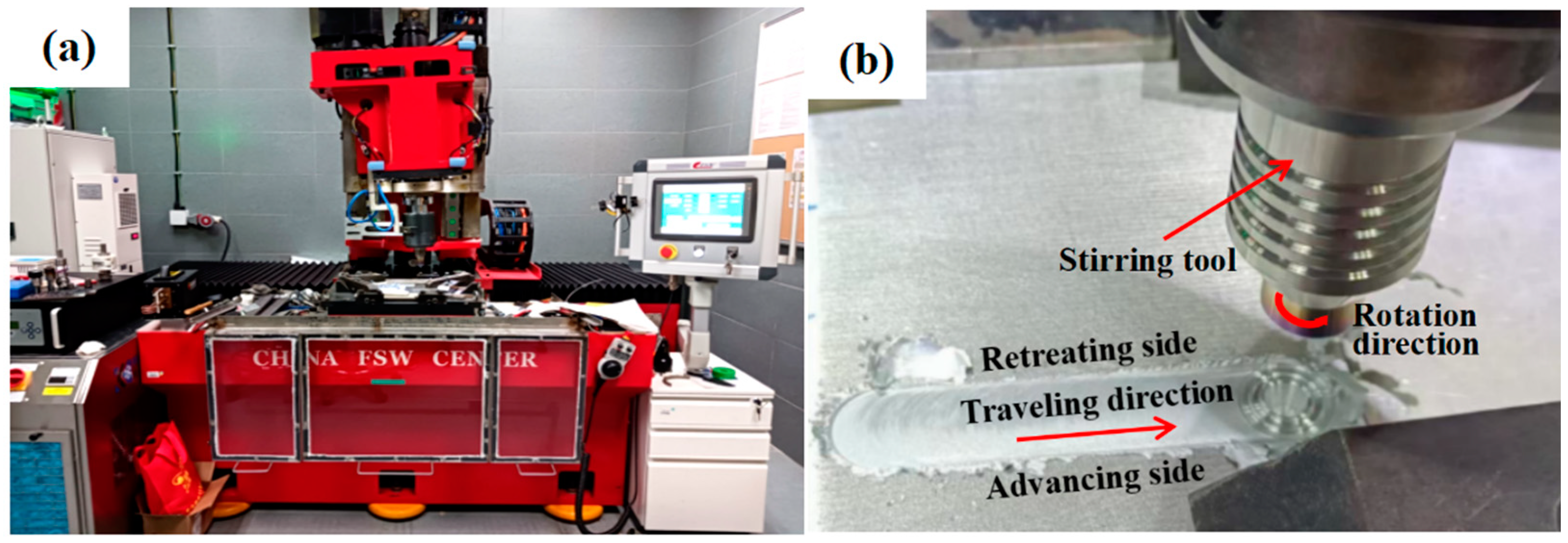
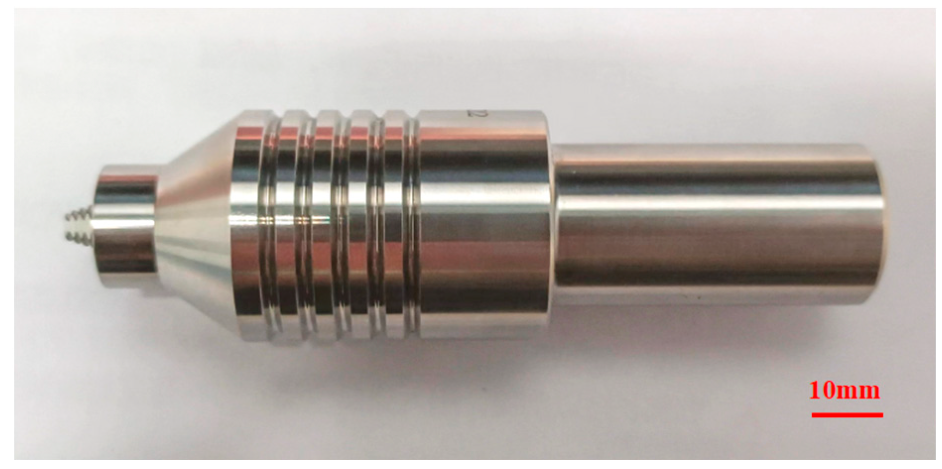
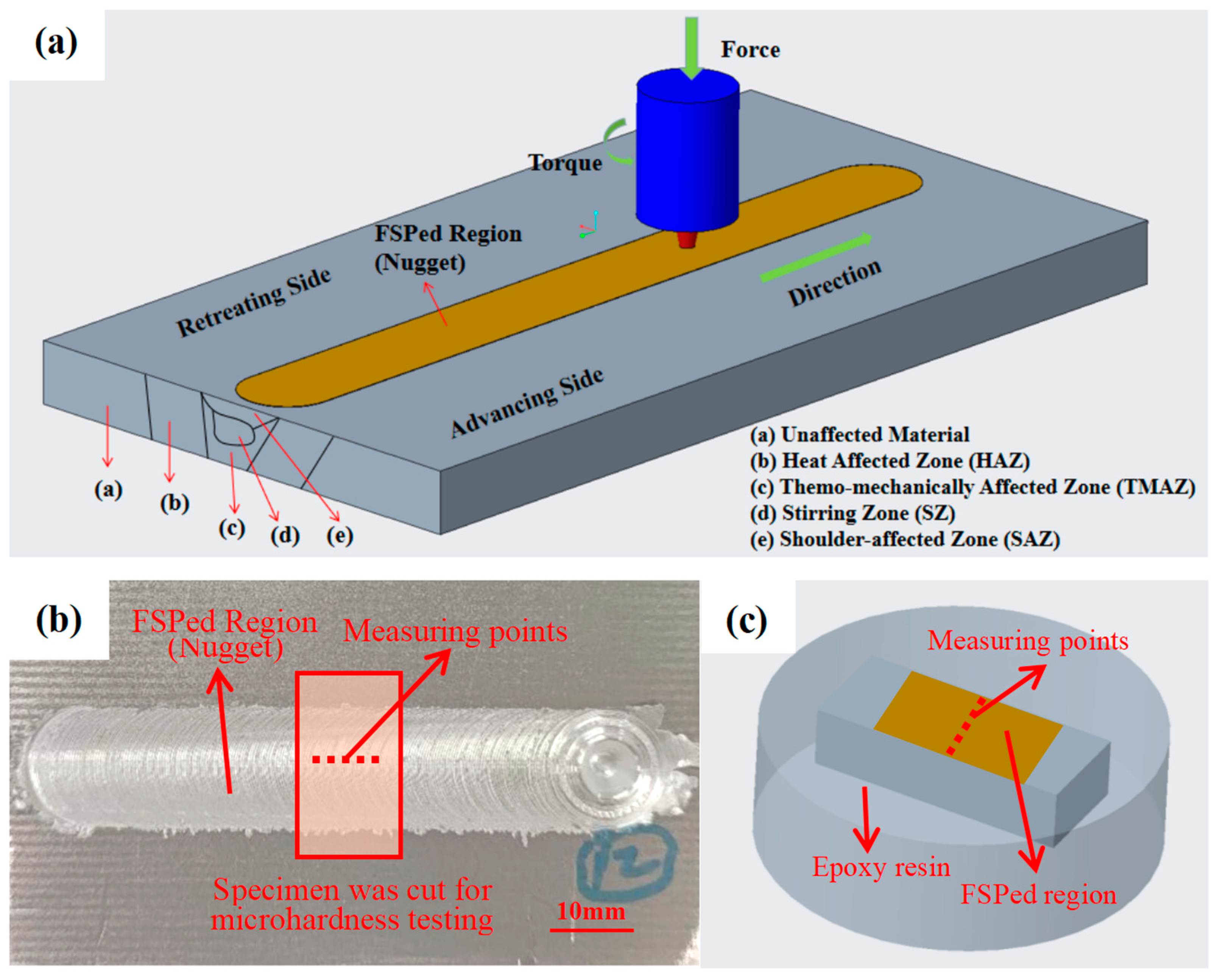
2.2. Friction Stir Processing (FSP)

FSP of the cast Al-Si-Fe-Mg was performed using a commercial friction stir welding machine (FSW-TS-M16, Beijing FSW Technology, Beijing, China), as shown in Figure 1. A non-consumable mechtrode with pin (made of H13 tool steel) was used for FSP as shown in Figure 2. Its geometric parameters are depicted in Table 2.

2.3. Design of Experiments

The processing parameters chosen for the design of experiments were rotation speed (w), transverse speed (v), penetration depth (PD), and tilt angle (TA). There were four levels for each parameter. Since multiple processing parameters were involved, it was necessary to explore the influence of each parameter. Using the conventional full factorial experimental method, the total number of experiments was up to 44 = 256, and the number of experiments and workload was huge. The orthogonal array method has been proven to be an effective approach in minimizing the number of experiments, as only 16 sets of trials are needed [27]. This method enables the assessment of impact of each parameter on the material performance and optimization of the parameters. A series of pilot experiments and a literature survey were conducted as part of the experimental procedure to identify both fixed and optimized FSP parameters. The initial phase was focused on pinpointing the crucial fixed parameters and calibrating their optimal values for the FSP process. Subsequent trials were designed to establish working windows for these four optimized parameters. Also, for the output variable (hardness), the process windows developed were based on the fact that all tests performed within the established parameter ranges produced good FSPed surfaces without defects. The assignment of levels to the factors is shown in Table 3, while Table 4 shows the standard orthogonal array. The fixed and optimized parameters of FSP are cataloged in Table 5, while Table 3 elucidates the span and gradations of the adjustable parameters. This methodological approach was underpinned by experimentation and testing to refine these windows of operation. The experimental design was meticulously executed using Minitab software (Version 19). In addition, the FSP parameters used in the experiments are shown in Table 5.

2.4. Characterization of FSPed Specimens

The FSPed specimens were cut into smaller pieces with dimensions of 20 mm × 8 mm × 5.5 mm using a wire EDM cutting machine, as shown in Figure 3b. After mounting with cold-curing epoxy resin, they were sequentially ground using different sandpapers (CAMI 80, 400, 800, 1000, 2500, and 5000 grits), polished using 1 μm diamond paste, then etched with 35% NaOH solution (75 g water + 25 g NaOH) and rinsed with 3% HNO3 solution (97 g H2O + 3 g HNO3). Subsequently, the specimens underwent the cleaning procedures including alcohol washing, ultrasonic cleaning in deionized water for 1 min, and thorough drying with a cold-air stream.
An X-ray diffractometer (XRD, MiniFlex 600, Rigaku, Tokyo, Japan) with Cu Kα radiation was used for identifying the phases on the surface of the FSPed specimens. OM (DMI3000M, Leica, Mannheim, Germany) was used for analyzing the surface of the FSPed specimens at a lower magnification. The scanning electron microscope (SEM, Hitachi S-3400N, Tokyo, Japan) equipped with an energy-dispersive X-ray spectrometer (EDS, Horiba EX-250, Kyoto, Japan) was utilized for microstructural and compositional analyses of the FSPed specimens at a higher magnification.
Hardness tests were carried out at the center of the surface of the FSPed specimens, as shown in Figure 3c. Five measuring points (each point was 0.5 mm apart) were selected for hardness measurements using an automated Vickers hardness tester (VH3100, Wilson, Lake Bluff, IL, USA) under a load of 0.2 kg and dwell time of 10 s. The average hardness was calculated from the results of those five points.

3. Results and Discussion

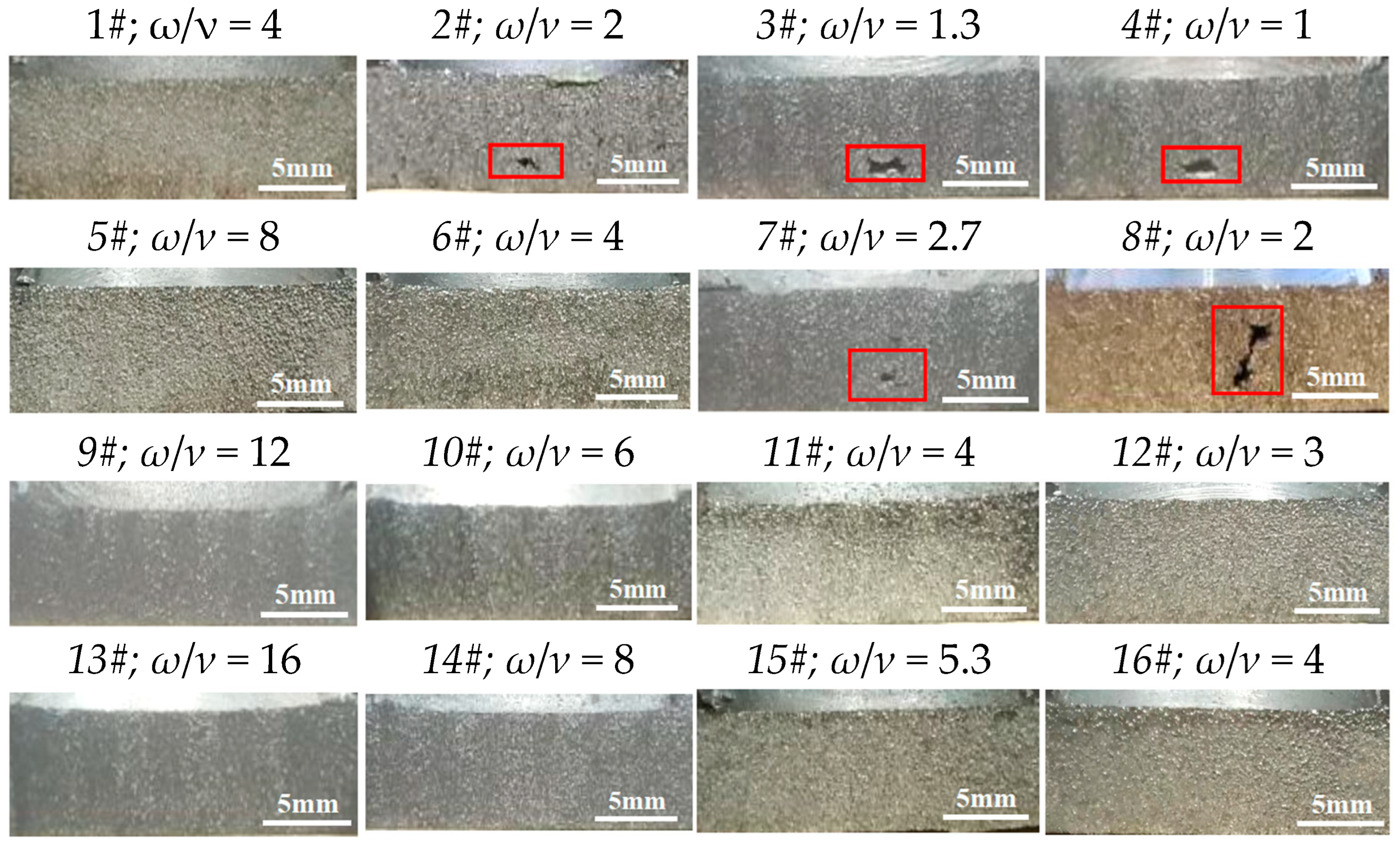
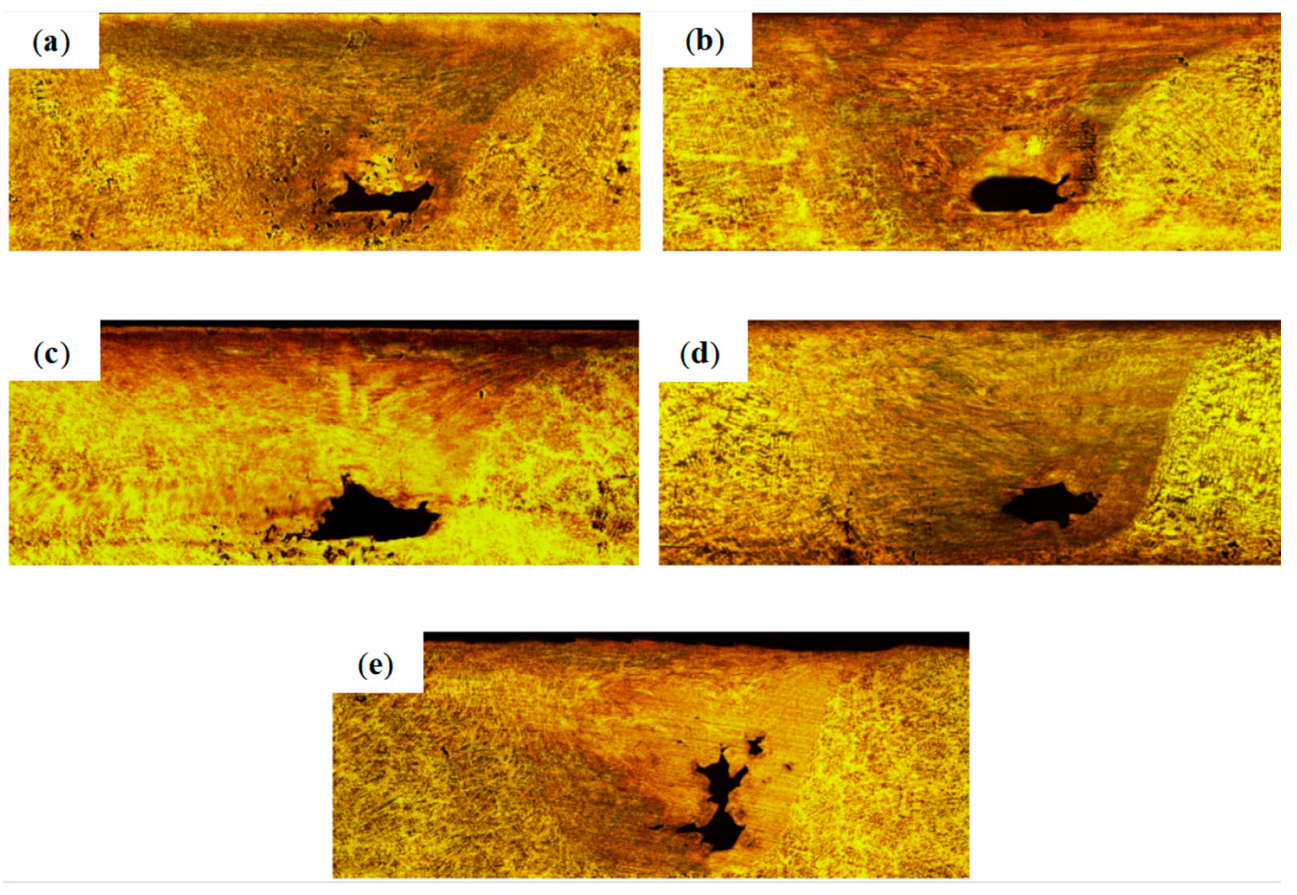
3.1. Macrostructure Analysis

According to Sharma et al. [28], the correlation between the average heat input (H) and the FSP parameters of Al-Si-Fe-Mg alloy is shown below:
H = 4 3 π 2 μ P ω R 3 v
where μ is the coefficient of friction, P is the pressure (Pa), R is the tool radius (m), and ω and ν denote the rotation speed and transverse speed, respectively. It can be simplified as follows:
H ω v
The heat input (peak temperature) achieved during FSP depends on ω and ν. An Increase in ω results in more heat input, whereas an increase in ν leads to less heat input.
To ascertain the temperature, axial force, and torque experienced by the Al-Si-Fe-Mg alloy during FSP, measurements were conducted under specific processing parameters, i.e., the rotation speed of 1200 rpm, a transverse speed of 400 mm/min, a tilt angle of 1.5°, and a penetration depth of 0 mm of the mechtrode, as illustrated in Figure 4. The axial force and torque were recorded using the pressure sensor and transducer, respectively, which were installed at the spindle (z-axis). The temperature was monitored using the thermocouple inserted at the shoulder of the mechtrode. During FSP, as the high-speed rotating pin was gradually inserted into the material during the plunging process, the temperature and torque also gradually increased, and the torque reached the peak value of 33 N·m, but the axial force firstly increased, then decreased, and finally increased to the peak value of 7 kN. When the high-speed rotation pin reached the predetermined insertion depth, during the dwelling process, the temperature continued to rise but the torque and axial force gradually decreased, and then during the traversing process, the temperature gradually increased slightly and reached the peak temperature of 370 °C, but the torque and axial force basically kept at the steady values of about 19 N·m and 5 kN, respectively. During the lifting process of the mechtrode, the temperature, axial force, and torque were gradually reduced to room temperature, 0 kN and 0 Nm, respectively.
The macroscopic views of various FSPed Al-Si-Fe-Mg are shown in Figure 5. Figure 6 shows the optical micrographs of cross-sections of five FSPed specimens with defects (2#, 3#, 4#, 7#, and 8#). Through analyzing the macrostructure and microstructure of the FSPed specimens fabricated at different combinations of the FSP parameters (mainly ω and ν), obvious pores, holes, and tunnel defects, etc., could be observed in some FSPed specimens. Under the parameters of 400 rpm (200 mm/min, 300 mm/min, and 400 mm/min) and 800 rpm (300 mm/min and 400 mm/min), significant pores, voids, and tunnel defects are found in these specimens. In other words, as the value of ω/ν was larger, the heat input was higher. Therefore, it can be concluded that:
(1)
When the value of ω/ν is less than 3, the FSPed specimens are likely to be defective.
(2)
The appearance of voids and tunnel defects largely depends on the effective heat input.
(3)
As ν increases, the heat input is insufficient, and the size of the tunnel defects becomes larger.

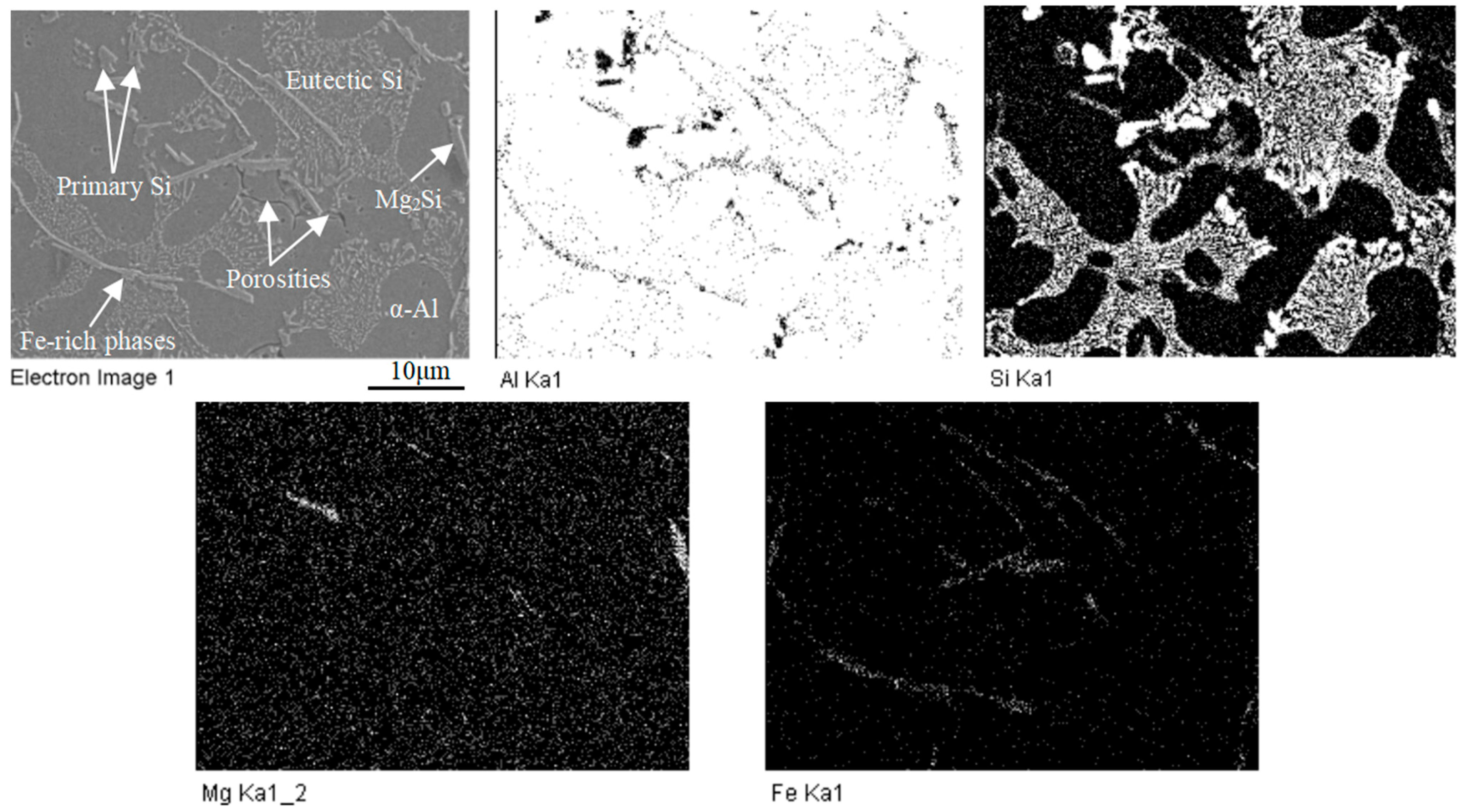
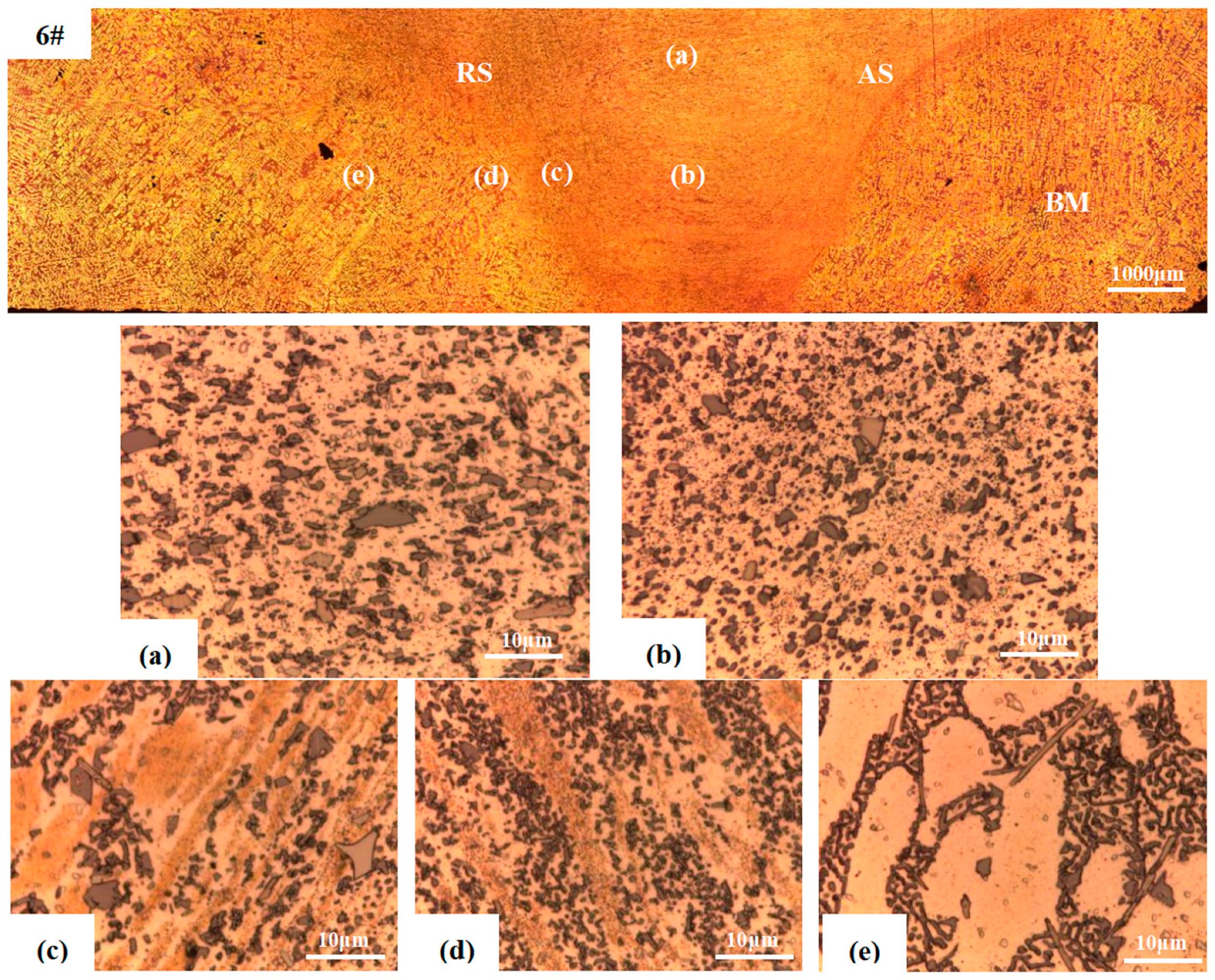
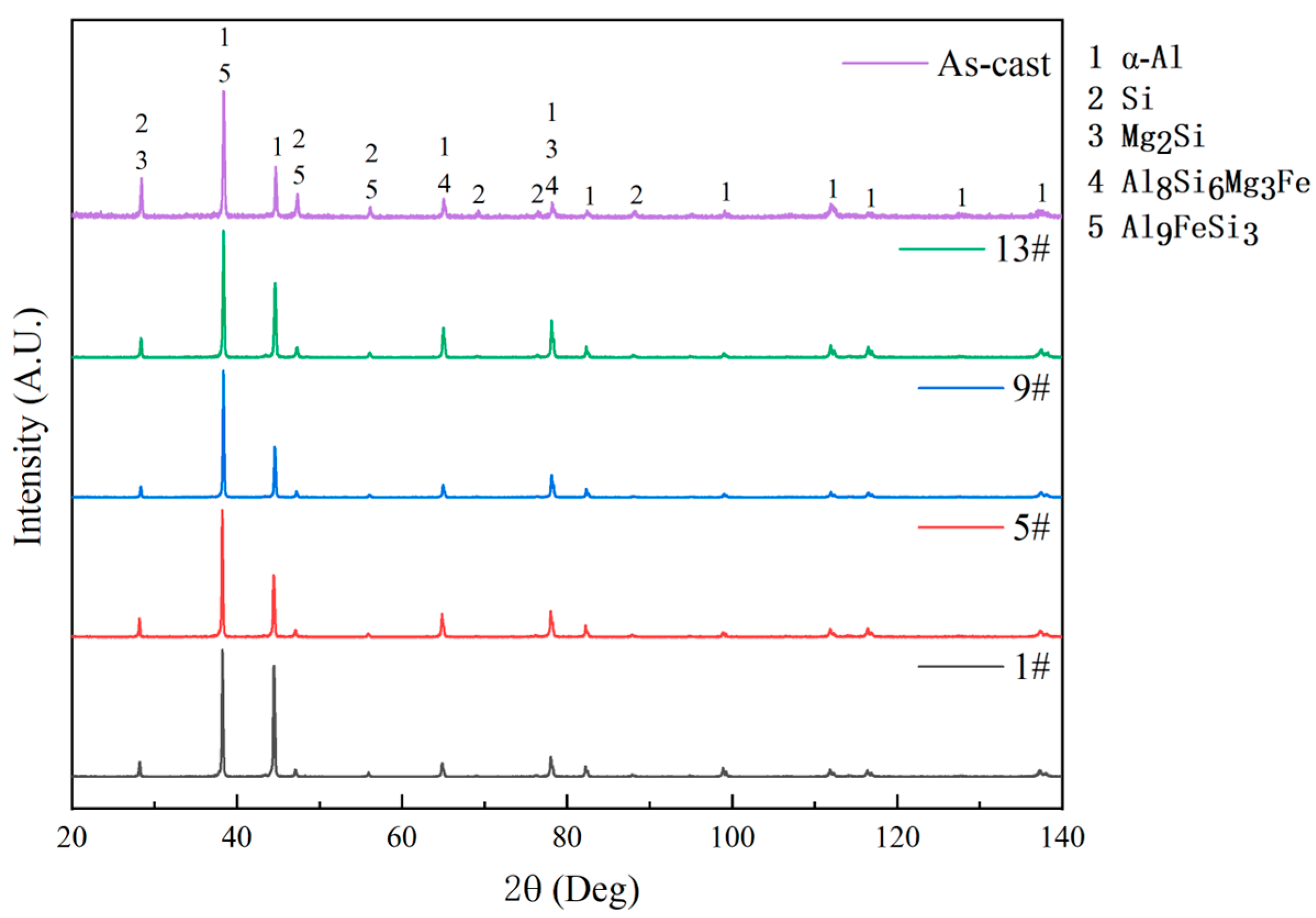
3.2. Microstructure Analysis
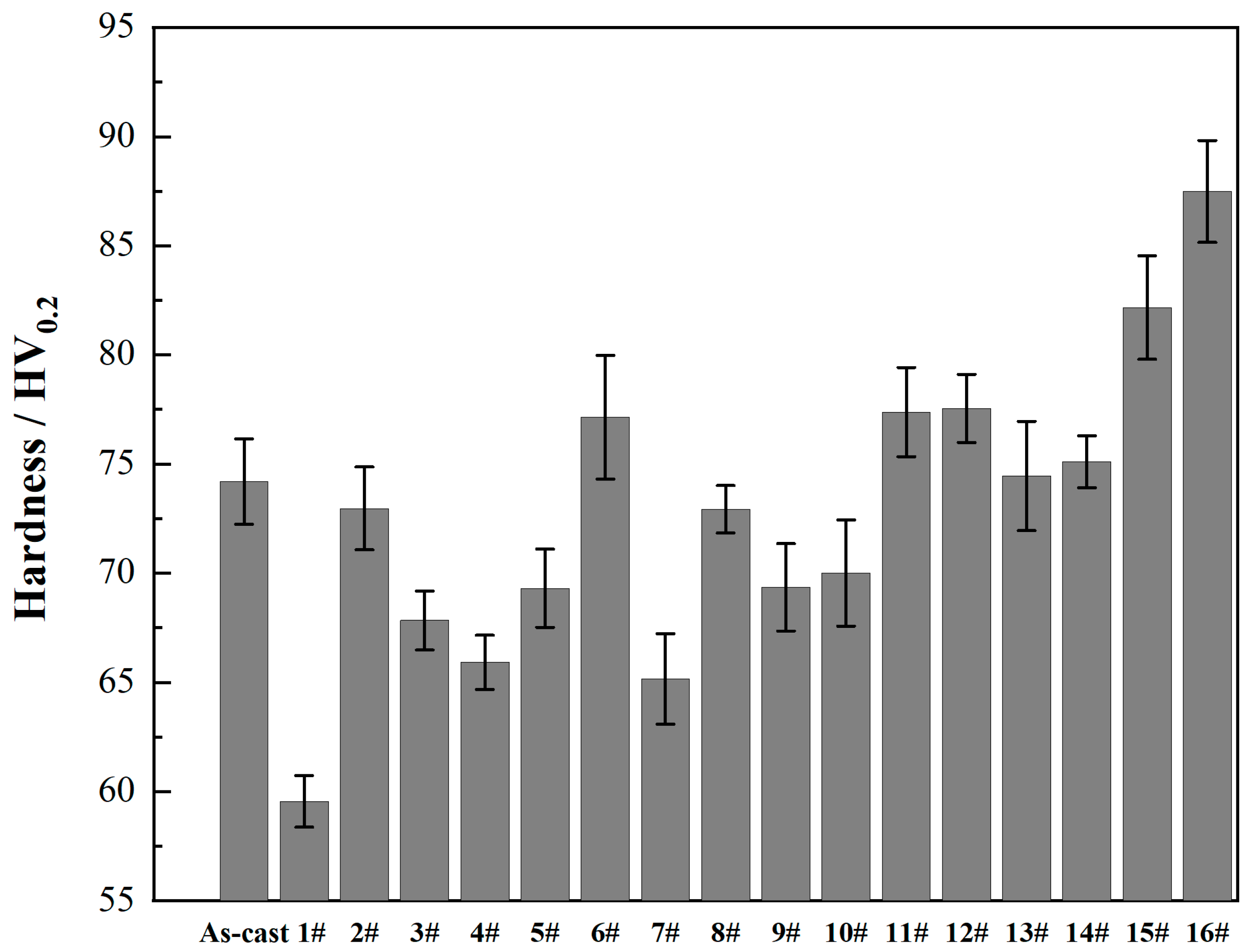
Figure 7 shows the SEM micrograph and EDS maps of the as-cast Al-Si-Fe-Mg. It consists of primary α-Al dendrites, coarse proeutectic primary Si crystals, network-like eutectic Si within the α-Al matrix, some intermetallic phases such as Mg2Si and long lath-shaped Fe-rich phases, and porosities. Mg dissolves and uniformly distributes in the α-Al matrix, but certain Mg and Si atoms aggregate to form Mg2Si. Combining Al, Si, and Mg, Fe tends to create Fe-rich intermetallic phases (Al9FeSi3 and Al8Si6Mg3Fe), which are randomly dispersed throughout the α-Al matrix. Notably, these Fe-rich phases generally exhibit needle-like and long lath-shaped morphologies. However, such heterogeneous microstructures and porosities are detrimental to the properties of Al-Si-Fe-Mg as they can become the origin of cracks and thus greatly affect the mechanical properties of this Al-Si-Fe-Mg.
Figure 8 shows the cross-section of the SZ of the FSPed Al-Si-Fe-Mg (6#). The right of the stir zone (SZ) is the retreating side (RS) and the left of the SZ is the advancing side (AS). In addition to the base material (BM), the FSPed specimen consists of four distinct zones, namely, SZ, shoulder-affected zone (SAZ), thermo-mechanically affected zone (TMAZ), and heat-affected zone (HAZ). Within the SZ of the FSPed Al-Si-Fe-Mg, FSP induces intense plastic deformation and frictional heating, leading to the formation of a recrystallized fine-grain microstructure. The TMAZ undergoes both temperature elevation and deformation during FSP, resulting in a highly deformed microstructure. The HAZ is unaffected by any mechanical effect, but only the thermal effect caused by the frictional heat generated by the rotation of the shoulder and pin. In addition, from the microstructures of different areas labelled in Figure 8, it was found that the grain size in SZ (Figure 8b) was significantly refined and the intermetallic and Si phases were uniformly distributed in the matrix, compared with that at the BM (Figure 8e). Due to smaller thermal effect and mechanical stirring, the a-Al phase in the TMAZ (Figure 8c) was elongated, but the Si phase was also more refined and distributed more uniformly than that at the BM.
Figure 9 shows the optical micrographs of the SZ of the FSPed specimens (1#, 5#, 9#, and 13#) with different rotation speeds (400, 800, 1200,, and 1600 rpm respectively) and the same transverse speed (100 mm/min.). The XRD patterns of the as-cast specimen and FSPed specimens (1#, 5#, 9#, and 16#) are shown in Figure 10. α-Al, eutectic Si, Mg2Si, and some Fe-rich phases (Al8Si6Mg3Fe and Al9FeSi3) were detected in the XRD patterns of all FSPed specimens. Compared with XRD pattern of the as-cast specimen, no new phase was detected after FSP, but there was a significant increase in the intensity a-Al peaks and decrease in the intensity of the Si and intermetallic peaks, indicating a substantial increase in the contents of Si, Mg, and Fe in the solid solution of a-Al owing to refinement and dissolution of the Si and intermetallic phases. As shown in Figure 9e, the coarse proeutectic Si, the eutectic Si distributed as network morphology, and the intermetallic phases in the as-cast Al-Si-Fe-Mg (Figure 7) were effectively fragmented. So, they were evenly distributed in the a-Al matrix of the FSPed Al-Si-Fe-Mg.
In addition, from the optical micrographs of the FSPed specimens as shown in Figure 9, the sizes of the Si phase and Fe-rich phases, and the density of the particles were analyzed through the software Image Pro Plus (Version 6.0), as shown in Figure 11. SEM-EDS maps in Figure 9e reveal an Al-rich matrix, silicon phase dominated by Si and Fe-rich phases with Fe, Mg, Si, and Al. The severe plastic deformation caused by FSP can effectively eliminate the porosities in the as-cast specimen and refine the sizes of a-Al and Si phases. The particle density in the microstructure increases significantly after FSP. Under a constant transverse speed of 100 mm/min, it was observed that an increase in the rotation speed led to a commensurate reduction in the size of both Si and intermetallic phases in the microstructure. Compared with the size of the Si phases and Fe-rich phases in the as-cast specimen (2.21 μm and 6.87 μm, respectively), all FSPed specimens achieved substantial refinement. It is worth noting that when the rotation speed was the highest (1600 rpm), the Si phases and Fe-rich phases in the LSAed specimen 13# were the finest, with sizes of 0.28 μm and 0.77 μm, respectively (reduced by 87% and 89%, respectively). Akbari et al. [29] investigated the effects of FSP parameters on the mechanical properties of aluminum composites. It was found that the size of Si particles and reinforcing particles decreased with the increase in rotation speed and the decrease in traverse speed of the mechtrode, which resulted in better mechanical properties of the FSPed region. Consequently, it can be inferred that as the rotation speed (peak temperature) increases and the transverse speed decreases, the degree of fragmentation during FSP will be enhanced which, in turn, significantly refines the Si and Fe-rich phase particles, resulting in a more homogeneous microstructure.

3.3. Hardness

Microhardness is crucial in the study of FSP of the hypereutectic Al-Si alloys due to their applications in tribology [30]. It is expected that enhancement in hardness can improve the wear resistance of the alloys. Figure 12 summarizes the surface hardness of all FSPed specimens (1# to 16#), in which the hardness value of the as-cast Al-Si-Fe-Mg was 74.2 HV0.2. From Figure 12, the microhardness of the specimens fabricated under different processing parameters is quite different. The results of Figure 9 and Figure 10 elucidate that an increase in rotation speed (from 400 to 1600 rpm), substantially diminished the size of the secondary phase particles and markedly elevated their density in the microstructure, culminating in an enhanced hardness. This enhancement is primarily attributed to the development of finer submicron Si particles (0.1–1 μm) within the matrix, which in turn fortifies the hardness of the FSPed specimens. The hardness of FSPed specimens at low and medium rotation speeds (400–800 rpm) was reduced (about 2%–20%), while the hardness of FSPed specimens at high rotation speeds (1200–1600 rpm) was increased significantly, with specimen 16# reached a maximum of 87.5 HV0.2, signifying an increment of 18%.
The variation in hardness of the FSPed specimens is predominantly governed by several factors: the grain size of the a-Al matrix, the size and distribution of Si particles, and the density of dislocations [31]. At lower rotation speeds, frictional heat during FSP induces dynamic recrystallization, which reduces dislocation density [32]. The softening effect of reduced dislocation density outweighs the fine grain strengthening of the refinement of a-Al grains and Si particles. Conversely, at higher rotation speeds, mechanical stirring imposes extensive plastic deformation, thereby elevating dislocation density. Simultaneously, the refinement of a-Al grains and Si particles contributes to grain size reduction in a-Al and reinforcement of Si. Under these conditions, the combined effect of increased dislocation density and the refinement of the a-Al matrix and Si particles culminates in a significant enhancement of hardness. The FSP parameters mainly affect the microstructure of the Al-Si-Fe-Mg alloy, which determines the properties of the alloy in turn. In the following section, the Taguchi method was used to analyze the effect of the parameters on the hardness, then optimize the appropriate combination of the processing parameters for the FSPed Al-Si-Fe-Mg alloy.

4. Statistical Modeling of Hardness

The model of performance correlates between the processing parameters and performance (i.e., hardness) of the FSPed Al-Si-Fe-Mg, and is based on optimization of the processing parameters. The quadratic polynomial model is one of the most commonly used models in performance fitting [33]. The quadratic polynomial model can be expressed as:
H a r d n e s s = a 1 + a 2 ω + a 3 v + a 4 T A + a 5 P D + a 6 ω v + a 7 ω T A + a 8 ω P D + a 9 v T A + a 10 v P D + a 11 T A P D + a 12 ω 2 + a 13 v 2 + a 14 T A 2 + a 15 P D 2
where a1 to a15 are constants, ω is rotation speed, v is transverse speed, PD is penetration depth, and TA is tilt angle.
The analysis of variance (ANOVA) was conducted using the software Minitab19. P-values of the model items with significant correlations (p ≤ 0.05) and fit error of the quadratic fit model are shown in Table 6. The p-values are related to the correlation between the input parameters and output responses. When the p-value is smaller, the correlation is better. The cut-off value for p was 0.05 in the experiments. The p-value less than or equal to 0.05 indicates that model items are significant. R2 determines the fit precision of the model. A higher R2 means higher the fit precision.
According to the ANOVA and data of the hardness shown in Table 7, the final quadratic regression Equation (4) is obtained after removing the insignificant items:
H a r d n e s s = 51.3808 + 2.4923 ω + 7.1819 v + 2.5489 T A + 1.2065 P D 1.9564 v T A
The final hardness regression model was used to predict the hardness value of each combination of the parameters. The comparison between experimental and predicted results, along with the corresponding errors, is presented in Table 7. From Table 7, it was found that the experimental value and predicted value of hardness from the regression model agreed well with an average percentage error of 2.44%. Therefore, this model can be used to predict the hardness of FSPed Al-Si-Fe-Mg under different combinations of the parameters for optimization.

5. Optimization of FSP Parameters

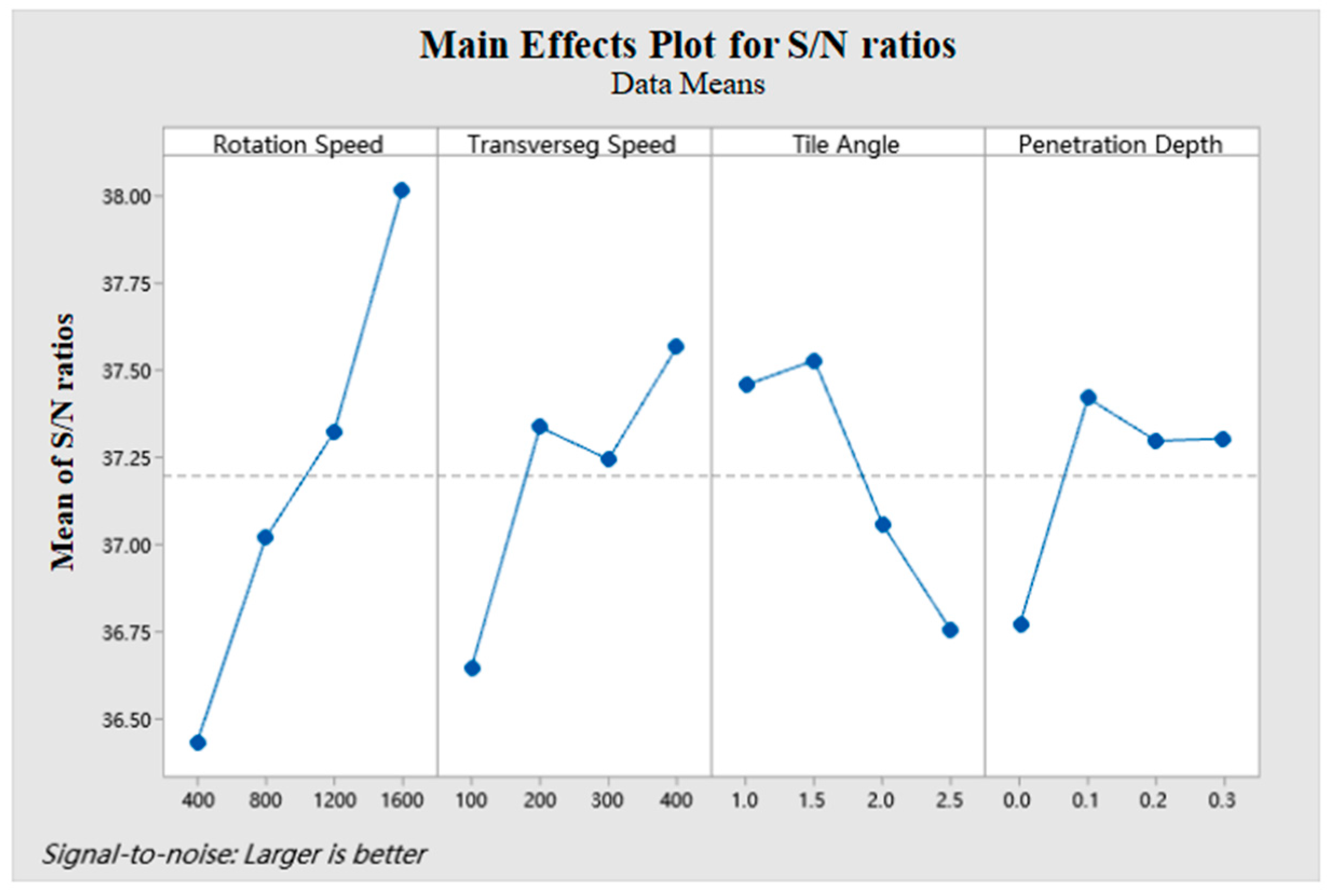
5.1. Analysis of S/N Ratio

The experiments were designed using the Taguchi method. It is based on the conversion of output values into signal-to-noise ratio (S/N ratio) as shown in Table 7 and Equation (5):
S / N = 10 log 1 n i n 1 y 2
where y is the response value of a given combination of factor levels (i.e., the values of hardness), and n donates the number of responses in that combination of factor levels (i.e., the number of hardness tests for one specimen). The properties fluctuation of the FSPed specimens is reflected by the S/N ratio. A high S/N ratio corresponds to a high hardness of the specimens. The response table for the S/N ratio of hardness is shown in Table 8. The main effect plots for hardness are plotted in Figure 13.
From Table 8, it can be seen that the effect of rotation speed on the hardness was the greatest, followed by transverse speed, tilt angle, and then penetration depth (d is the difference between max and min). Figure 13 shows that the optimum combination of the parameters for hardness is: rotation speed = 1600 rpm, transverse speed = 400 mm/min, tilt angle = 1.5°, and penetration depth = 0.1 mm.

5.2. Analysis of Variance (ANOVA)

The ANOVA test was carried out to identify the FSP parameters which were statistically significant. The purpose was to study the significance of the parameters affecting the hardness of the FSPed specimens. The significance of the parameters was determined by the F test and the p-value of the ANOVA table. In general, the larger the F-value, the greater the effect of the change of the parameters on the hardness. When the p-value is inferior or equal to the significance level of 0.05, the effect of the parameters is significant, and while the p-value is greater than 0.05, the effect of the parameter is not significant [34]. ANOVA results for the hardness of the S/N ratio are shown in Table 9. The results of ANOVA indicate that the FSP parameters were highly significant factors affecting the hardness of the FSPed specimens in the descending order: rotation speed, transverse speed, tile angle, and penetration depth. Among them, the rotation speed (w) was a significant factor. The percentage of contribution of the rotation speed, transverse speed, tilt angle, and penetration depth is shown in Figure 14.
Additionally, it is generally known that the microstructure and mechanical properties of the FSPed Al alloys are closely related to the thermo-mechanical effect and dynamic recrystallization behavior during FSP [35], and these two effects are controlled by the FSP parameters (i.e., rotation speed, transverse speed, tilt angle, and penetration depth). According to Equation (2), the heat input during FSP is mainly related to the rotation speed and transverse speed [28], while the tilt angle and penetration depth may affect the material flow and thermo-mechanical effects [36]. Therefore, a more comprehensive understanding of the microstructure and hardness of the Al-Si-Fe-Mg alloy can be achieved by examining the interplay between these parameters. The interaction effect (contour plot) of the FSP parameters on hardness is shown in Figure 15. The region with the lowest hardness is depicted by the dark blue area, while the dark green area represents the region with the highest hardness. As mentioned in Section 3, the microstructure and hardness of the FSPed specimens are affected by multiple factors: the grain size of the a-Al matrix, the size and distribution of Si particles, and the density of dislocations [31]. From Figure 15a–c, it was also found that the hardness increases as the rotation speed increases, and the highest hardness appears at 1600 rpm. An appropriate increase in rotation speed will assist in homogenizing the microstructure, increasing dislocation density, refinement of grains, and fragmentation of secondary phases, thereby increasing hardness. It is also evident that the relationship between different parameters on hardness is not a straightforward linear correlation. Based on Figure 5d–f, it can be observed that the region with the highest hardness predominantly occurs within the transverse speed range of 350–400 mm/min, tilt angle between 1–1.5°, and penetration depth of 0.15–0.25 mm. Within the above narrow parameter range, the increase in hardness may be attributed to the fact that the downward forging action of material by the shoulder during FSP can be effectively increased, thereby enhancing the microstructure of the material [37].

5.3. Optimization Results and Experimental Verification

According to the main effects of S/N ratio (Table 8 and Figure 13), the optimal combination of parameters for enhanced hardness is: rotation speed = 1600 rpm (level 4), transverse speed = 400 mm/min (level 4), tilt angle = 1.5° (level 2), and penetration depth = 0.1 mm (level 2). Additionally, upon inputting the optimal parameters into the established quadratic fitting Equation (4), as shown in Table 10, the predicted value obtained is 81.9 HV0.2. The confirmation test was carried out using the optimum parameters and the experimental hardness of the specimen is 82.8 HV0.2. The validation experiment demonstrated that the actual results closely aligned with the predicted values, exhibiting a mere 1.1% error margin. Moreover, the outcomes were consistently surpassed those of the 16 sets derived from the orthogonal experiments, indicating a significant optimization effect.

6. Conclusions

Surface modification of as-cast Al-Si-Fe-Mg alloy was successfully achieved via FSP, FSP is an effective method to eliminate the cast defects (e.g., porosity), refine the grains, fragment of Si and intermetallic phases, and enhance the mechanical properties (hardness). FSP parameters include rotation speed, transverse speed, tilt angle, and penetration depth, etc., which have a crucial impact on the microstructure and mechanical properties of Al-Si-Fe-Mg. Among them, the heat input during FSP is mainly determined by the rotation speed and transverse speed (w/v). This study found that when the w/v ratio is less than 3, i.e., the heat input is insufficient, voids and tunnel defects appear in the FSP region. The size of the defects increases with the increase of transverse speed. Using the self-developed pressure, torque, and temperature sensors, the sensor data of the 12# specimen were obtained when w/v was equal to 3 (no defects). It was concluded that the temperature was maintained in the range of 325–370 °C, and the torque and axial force were maintained at 19 N·m and 5 kN, respectively.
This study innovatively employed the Taguchi method in conjunction with mathematical regression analysis to establish the quadratic polynomial model shown in Equation (4) for predicting the hardness (accuracy of 97.56%) and determine the optimal combination of FSP parameters that yielded the finest microstructure and optimal hardness (82.8 HV0.2). The optimal process parameters include: a rotation speed of 1600 rpm, a transverse speed of 400 mm/min, a tilt angle of 1.5°, and a penetration depth of 0.1 mm. Analysis of variance (ANOVA) showed that rotation speed was the most significant parameter, followed by transverse speed, tilt angle, and penetration depth. An extensive analysis of the interaction of each parameter was conducted, and it was found that the hardness increased with the increase in rotation speed. The maximum value was reached when the rotation speed was 1600 rpm. In addition, the area with the highest hardness in the contour plots mainly appeared in the range of transverse speed of 350 mm/min–400 mm/min, tilt angle of 1–1.5°, and penetration depth of 0.15–0.25 mm leading to uniform microstructure, increased dislocation density, grain refinement, and fragmentation of second phase particles.
As society’s demand for high-performance manufacturing continues to grow, intelligent FSW/FSP is a new research direction, in which data acquisition is a crucial issue. In this study, the innovative application of sensors was used to obtain temperature, force and torque in situ during FSP. These recorded data can directly reflect the material processing characteristics and have guiding significance for the engineering application of FSP. Establishing the relationship between various variables (rotation speed, transverse speed, force, temperature, and torque) and processing defects/material properties is a novel research direction.

Author Contributions

Methodology, Q.L., D.G. and L.-M.T.; Investigation, Q.L., X.C., K.L., V.A.M.C., K.-H.L. and Z.X.; Writing—original draft, Q.L. and X.C.; Writing—review & editing, V.A.M.C., K.-H.L. and C.-T.K.; Supervision, D.G. and C.-T.K.; Project administration, Z.X., D.G., L.-M.T. and C.-T.K.; Funding acquisition, V.A.M.C., D.G., L.-M.T. and C.-T.K. All authors have read and agreed to the published version of the manuscript.

Funding

Science and Technology Development Fund of Macao (Grant No. 0050/2019/AMJ, 0015/2021/AFJ, 0087/2021/A2 and 0110/2023/AMJ) and the Institute for the Development and Quality, Macau.

Institutional Review Board Statement

Not applicable.

Informed Consent Statement

Not applicable.

Data Availability Statement

Data is available upon requested.

Conflicts of Interest

The authors declare no conflict of interest.

References

  1. Tsai, F.Y.; Kao, P.W. Improvement of mechanical properties of a cast Al–Si base alloy by friction stir processing. Mater. Lett. 2012, 80, 40–42. [Google Scholar] [CrossRef]
  2. Izumi, T. Method of Making Internal Combustion Engine Cylinder Made of an Aluminum Alloy Enriched with Wear Resistant Component on the Inside Surface. U.S. Patent 3,536,123, 27 October 1970. [Google Scholar]
  3. Dash, S.S.; Chen, D.A. Review on Processing–Microstructure–Property Relationships of Al-Si Alloys: Recent Advances in Deformation Behavior. Metals 2023, 13, 609. [Google Scholar] [CrossRef]
  4. Vijeesh, V.; Ravi, M.; Prabhu, K.N. The Effect of the Addition of Strontium and Cerium Modifiers on Microstructure and Mechanical Properties of Hypereutectic Al-Si (LM30) Alloy. Mater. Perform. Charact. 2013, 2, 296–307. [Google Scholar] [CrossRef]
  5. Mallick, A.; Setti, S.G.; Sahu, R.K. Centrifugally cast functionally graded materials Fabrication and challenges for probable automotive cylinder liner application. Ceram. Int. 2023, 49, 8649–8682. [Google Scholar] [CrossRef]
  6. Mbuya, T.O.; Odera, B.O.; Ng’ang’a, S.P. Influence of iron on castability and properties of aluminium silicon alloys: Literature review. Int. J. Cast Met. Res. 2016, 16, 451–465. [Google Scholar] [CrossRef]
  7. Li, Q.; Qiu, F.; Dong, B.X.; Yang, H.Y.; Shu, S.L.; Zha, M.; Jiang, Q.C. Investigation of the influences of ternary Mg addition on the solidification microstructure and mechanical properties of as-cast Al–10Si alloys. Mater. Sci. Eng. A 2020, 798, 140247. [Google Scholar] [CrossRef]
  8. Rao, A.G.; Ravi, K.R.; Ramakrishnarao, B.; Deshmukh, V.P.; Sharma, A.; Prabhu, N.; Kashyap, B.P. Recrystallization Phenomena During Friction Stir Processing of Hypereutectic Aluminum-Silicon Alloy. Metall. Mater. Trans. A 2012, 44, 1519–1529. [Google Scholar] [CrossRef]
  9. Sakow, S.; Tokunaga, T.; Ohno, M.; Matsuura, K. Microstructure refinement and mechanical properties improvement of Al-Si-Fe alloys by hot extrusion using a specially designed high-strain die. J. Mater. Process. Technol. 2020, 277, 116447. [Google Scholar] [CrossRef]
  10. Liu, X.; Beausir, B.; Zhang, Y.; Gan, W.; Yuan, H.; Yu, F.; Esling, C.; Zhao, X.; Zuo, L. Heat-treatment induced defect formation in α-Al matrix in Sr-modified eutectic Al–Si alloy. J. Alloys Compd. 2018, 730, 208–218. [Google Scholar] [CrossRef]
  11. Zhang, M.; Tian, Y.; Zheng, X.; Zhang, Y.; Chen, L.; Wang, J. Research Progress on Multi-Component Alloying and Heat Treatment of High Strength and Toughness Al-Si-Cu-Mg Cast Aluminum Alloys. Materials 2023, 16, 1065. [Google Scholar] [CrossRef] [PubMed]
  12. Atxaga, G.; Pelayo, A.; Irisarri, A.M. Effect of microstructure on fatigue behaviour of cast Al–7Si–Mg alloy. Mater. Sci. Technol. 2013, 17, 446–450. [Google Scholar] [CrossRef]
  13. Li, Y.; Jiang, Y.; Liu, B.; Luo, Q.; Hu, B.; Li, Q. Understanding grain refining and anti Si-poisoning effect in Al-10Si/Al-5Nb-B system. J. Mater. Sci. Technol. 2021, 65, 190–201. [Google Scholar] [CrossRef]
  14. Cheng, W.; Liu, C.Y.; Ge, Z.J. Optimizing the mechanical properties of Al–Si alloys through friction stir processing and rolling. Mater. Sci. Eng. A 2021, 804, 140786. [Google Scholar] [CrossRef]
  15. Zhao, Y.; Liu, J.; Topping, T.D.; Lavernia, E.J. Precipitation and aging phenomena in an ultrafine grained Al-Zn alloy by severe plastic deformation. J. Alloys Compd. 2021, 851, 156931. [Google Scholar] [CrossRef]
  16. Tang, Y.; Tomita, Y.; Horita, Z. Mechanical Properties and Microstructures of Highly Fe-Containing Al–Mg–Si Alloys Processed by Severe Plastic Deformation under High Pressure. Mater. Trans. 2023, 64, 448–457. [Google Scholar] [CrossRef]
  17. Bates, W.P.; Patel, V.; Rana, H.; Andersson, J.; Jeroen, D.B.; Mattias, I.; Livan, F. Properties Augmentation of Cast Hypereutectic Al–Si Alloy Through Friction Stir Processing. Met. Mater. Int. 2022, 29, 215–228. [Google Scholar] [CrossRef]
  18. Meenia, S.; Khan, F.; Babu, S.; Immanuel, R.J.; Panigrahi, S.K.; Janaki-Ram, G.D. Particle refinement and fine-grain formation leading to enhanced mechanical behaviour in a hypo-eutectic Al–Si alloy subjected to multi-pass friction stir processing. Mater. Charact. 2016, 113, 134–143. [Google Scholar] [CrossRef]
  19. Saini, N.; Dwivedi, D.K.; Jain, P.K.; Singh, H. Surface Modification of Cast Al-17%Si Alloys Using Friction Stir Processing. Procedia Eng. 2015, 100, 1522–1531. [Google Scholar] [CrossRef]
  20. Ma, L.; Zhou, C.; Shi, Y.; Cui, Q.; Ji, S.; Yang, K. Grain-Refinement and Mechanical Properties Optimisation of A356 Casting Al by Ultrasonic-Assisted Friction Stir Processing. Met. Mater. Int. 2021, 27, 5374–5388. [Google Scholar] [CrossRef]
  21. Basak, A.K.; Pramanik, A.; Prakash, C.; Shankar, S.; Sehgal, S.S. Microstructure and micro-mechanical properties of friction stir processed Al 5086-based surface composite. Mater. Today Commun. 2023, 35, 105830. [Google Scholar] [CrossRef]
  22. Lakshminarayanan, A.K.; Balasubramanian, V. Process parameters optimization for friction stir welding of RDE-40 aluminium alloy using Taguchi technique. Trans. Nonferrous Met. Soc. China 2008, 18, 548–554. [Google Scholar] [CrossRef]
  23. Premnath, A. Optimization of the Process Parameters on the Mechanical and Wear Properties of Al-SiC Nano-Composites Fabricated by Friction Stir Processing Using Desirability Approach. Silicon 2019, 12, 665–675. [Google Scholar] [CrossRef]
  24. Ahmadkhaniha, D.; Sohi, M.H.; Zarei-Hanzaki, A.; Bayazid, S.M.; Saba, M. Taguchi optimization of process parameters in friction stir processing of pure Mg. J. Magnes. Alloys 2015, 3, 168–172. [Google Scholar] [CrossRef]
  25. Butola, R.; Ranganath, M.S.; Murtaza, Q. Fabrication and optimization of AA7075 matrix surface composites using Taguchi technique via friction stir processing (FSP). Eng. Res. Express 2019, 1, 25015. [Google Scholar] [CrossRef]
  26. Ghetiya, N.D.; Bharti, S.; Patel, K.M.; Sudhir, K.; Koloor, R.; Saeid, S. An insight on optimization of FSP process parameters for the preparation of AA5083/(SiC-Gr) hybrid surface composites using the response surface methodology. Compos. Adv. Mater. 2023, 32, 1–13. [Google Scholar] [CrossRef]
  27. Gologlu, C.; Sakarya, N. The effects of cutter path strategies on surface roughness of pocket milling of 1.2738 steel based on Taguchi method. J. Mater. Process. Technol. 2008, 206, 7–15. [Google Scholar] [CrossRef]
  28. Sharma, V.; Prakash, U.; Kumar, B.V.M. Surface composites by friction stir processing: A review. J. Mater. Process. Technol. 2015, 224, 117–134. [Google Scholar] [CrossRef]
  29. Akbari, M.; Asadi, P.; Zolghadr, P.; Khalkhali, A. Multicriteria optimization of mechanical properties of aluminum composites reinforced with different reinforcing particles type. J. Mater. Res. 2017, 232, 1789–1796. [Google Scholar] [CrossRef]
  30. Lu, D.H.; Wei, S.S.; Zhou, M.; Jiang, Y.H.; Zhou, R. Effects of the Parameters of Friction Stir Processing on Silicon Particles and Hardness in Hypereutectic Al-Si Alloys. Adv. Mater. Res. 2010, 148–149, 1689–1694. [Google Scholar] [CrossRef]
  31. Yadav, D.; Bauri, R. Effect of friction stir processing on microstructure and mechanical properties of aluminium. Mater. Sci. Eng. A 2012, 539, 85–92. [Google Scholar] [CrossRef]
  32. García-Bernal, M.A.; Mishra, R.S.; Verma, R.; Hernández-Silva, D. Influence of friction stir processing tool design on microstructure and superplastic behavior of Al-Mg alloys. Mater. Sci. Eng. A 2016, 670, 9–16. [Google Scholar] [CrossRef]
  33. Jiang, F.; Li, J.F.; Yan, L.; Sun, J.; Zhang, S. Optimizing end-milling parameters for surface roughness under different cooling/lubrication conditions. Int. J. Adv. Manuf. Technol. 2010, 51, 841–851. [Google Scholar] [CrossRef]
  34. Bararpour, S.M.; Aval, H.J.; Jamaati, R.; Javidani, M. Effect of initial heat treatment of A390 alloy on microstructure and tribological behavior of friction surfaced coating. Surf. Coat. Technol. 2024, 478, 130359. [Google Scholar] [CrossRef]
  35. Patel, V.; Li, W.; Vairis, A.; Badheka, V. Recent Development in Friction Stir Processing as a Solid-State Grain Refinement Technique: Microstructural Evolution and Property Enhancement. Crit. Rev. Solid State Mater. Sci. 2019, 44, 378–426. [Google Scholar] [CrossRef]
  36. Kumar, J.; Patra, P.; Mondal, A.K.; Verma, R.K. Investigation on thermo-mechanical performances of friction stir welding of aluminum alloys (AA6063). Weld. Int. 2022, 36, 316–330. [Google Scholar] [CrossRef]
  37. Padhy, G.K.; Wu, C.S.; Gao, S. Friction stir based welding and processing technologies-processes, parameters, microstructures and applications: A review. J. Mater. Sci. Technol. 2018, 34, 1–38. [Google Scholar] [CrossRef]
Figure 1. (a) Setup and (b) mechtrode for FSP.
Coatings 14 00222 g001
Figure 2. Mechtrode used for FSP.
Coatings 14 00222 g002
Figure 3. (a) Schematic diagram of FSP, (b) typical FSPed specimen, and (c) mounted specimen for micro-hardness testing.
Coatings 14 00222 g003
Figure 4. Temporal variation of temperature, force, and torque of the mechtrode operated at a rotation speed of 1200 rpm and transverse speed of 400 mm/min.
Coatings 14 00222 g004
Figure 5. Macrostructure of the cross-section of FSPed Al-Si-Fe-Mg without or with defects (shown in the red boxes).
Coatings 14 00222 g005
Figure 6. Optical micrographs of cross-sections of five FSPed specimens with defects: (a) 2#, (b) 3#, (c) 4#, (d) 7#, and (e) 8#.
Coatings 14 00222 g006
Figure 7. SEM micrograph and EDS maps of Al, Si, Mg, and Fe of as-cast Al-Si-Fe-Mg.
Coatings 14 00222 g007
Figure 8. Optical micrographs of cross-sections of the FSPed specimen (6#), (a,b) SZ, (c) TMAZ, (d) HAZ, and (e) BM.
Coatings 14 00222 g008
Figure 9. Microstructure of SZ of the FSPed specimens: (a) 1#, (b) 5#, (c) 9#, and (d) 13# corresponding to 400, 800, 1200, and 1600 rpm, respectively; and (e) typical SEM-EDS maps of the FSPed specimen (13#).
Coatings 14 00222 g009
Figure 10. XRD spectra of the as-cast specimen and FSPed specimens (1#, 5#, 9#, and 13#) corresponding to 400, 800, 1200, and 1600 rpm, respectively.
Coatings 14 00222 g010
Figure 11. Size of Si phase and Fe-rich phases, and particle density of the as-cast specimen and FSPed specimens (1#, 5#, 9#, and 13#).
Coatings 14 00222 g011
Figure 12. Bar chart showing the average microhardness of the as-cast and SZ of FSPed specimens.
Coatings 14 00222 g012
Figure 13. Plots of main effects for hardness.
Coatings 14 00222 g013
Figure 14. Percentage of contribution of factors.
Coatings 14 00222 g014
Figure 15. Interaction effect (contour plot) of FSP parameters on hardness: (a) influence of w and v, (b) influence of w and TA, (c) influence of w and PD, (d) influence of v and TA, (e) influence of v and PD, and (f) influence of PD and TA.
Coatings 14 00222 g015
Table 1. Chemical compositions of the as-cast Al-Si-Fe-Mg alloy.
ElementAlSiFeMg
wt.%Bal17.871.000.56
Table 2. Geometric parameters of the mechtrode.
Tool MaterialH13
Tool shoulder diameter15 mm
Tool pin profileTapered threaded tool
Pin diameter at root6.2 mm
Pin diameter at tip3.6 mm
Pin cone angle15°
Pin length4.7 mm
Table 3. Assignment of levels to the factors.
ParameterSymbolUnitLevel 1Level 2Level 3Level 4
Rotation speedwrpm40080012001600
Transverse speedvmm/min100200300400
Tilt angleTAdegree11.522.5
Penetration depthPDmm00.10.20.3
Table 4. Standard orthogonal arrays of 16 groups according to Taguchi’s suggestion.
Test Numberw (rpm)v (mm/min)TA (°)PD (mm)
140010010
24002001.50.1
340030020.2
44004002.50.3
58001001.50.2
680020010.3
78003002.50
880040020.1
9120010020.3
1012002002.50.2
11120030010.1
1212004001.50
1316001002.50.1
14160020020
1516003001.50.3
16160040010.2
Table 5. FSP parameters used in this study.
FSP ParameterValue
Rotation direction of toolAnti-clockwise
Rotation speed400, 800, 1200, 1600 rpm
Transverse speed100, 200, 300, 400 mm/min
Penetration depth0, 0.1, 0.2, 0.3 mm
Tile angle1°, 1.5°, 2°, 2.5°
Plunged speed30 mm/min
z-axis lifting speed50 mm/min
z-axis lifting height20 mm
Plunged delay time2 s
Lift delay time1 s
Table 6. p-values and fit error of quadratic fit model.
Equationp-ValueR2 (%)
-ConstantwvTAPDvTA-
Hardness0.0000.0390.0020.0020.0480.04497.56
Table 7. Hardness responses with input parameters of FSPed specimens.
No.w (rpm)v (mm/min)TA (°)PD (mm)S/NHV0.2
(Experiment)
HV0.2
(Prediction)
Error
(%)
As-cast-----74.2--
1111135.5059.662.95.46
2122237.2172.567.96.31
3133336.6367.869.11.88
4144436.3865.966.30.64
5212336.8269.368.41.37
6221437.7276.974.23.52
7234136.2865.265.80.98
8243237.2672.971.71.68
9313436.8269.472.64.67
10324336.9070.071.41.98
11331237.7777.479.52.71
12342137.7977.678.20.82
13414237.4474.573.31.59
14423137.5175.172.83.02
15432438.2982.281.11.36
16441338.8487.588.41.05
Table 8. Response table for signal-to-noise ratios (S/N ratios) of hardness.
LevelRotation SpeedTransverse SpeedTilt AnglePenetration Depth
136.4336.6437.4636.77
237.0237.3437.5337.42
337.3237.2437.0637.30
438.0237.5736.7537.30
Delta (d)1.590.920.780.65
Ranking1234
Table 9. ANOVA for hardness.
SourceDFSeq SSAdj SSAdj MSF-Valuep-ValueContribution
w3371.30371.30123.76815.450.02552.34%
v3129.10129.1043.0355.370.10018.20%
TA3122.50122.5040.8345.100.10717.27%
PD362.4662.4620.8212.600.2278.81%
Error324.0324.038.011--3.38%
Total15709.41----100.00%
Table 10. Experimental verification of the optimal parameters for the FSP trials.
NO.w (rpm)v (mm/min)TA (°)PD (mm)HV0.2
(Experiment)
HV0.2
(Prediction)
Error
(%)
1442282.881.91.1
Disclaimer/Publisher’s Note: The statements, opinions and data contained in all publications are solely those of the individual author(s) and contributor(s) and not of MDPI and/or the editor(s). MDPI and/or the editor(s) disclaim responsibility for any injury to people or property resulting from any ideas, methods, instructions or products referred to in the content.

