Article

Axial Compression Bearing Capacity of Bolted Drum-Shaped Spherical Shell Joints: Experimental and Numerical Analysis

1
College of Intelligent Construction, Shanxi Electronic Science and Technology Institute, Linfen 041000, China
2
College of Civil Engineering, Taiyuan University of Technology, Taiyuan 030024, China
3
Shanxi 6th Construction Group Co., Ltd., Taiyuan 030024, China
4
College of Architectural Engineering, Shanxi Vocational University of Engineering Science and Technology, Taiyuan 030000, China
5
Faculty of Architecture, Civil and Transportation Engineering, Beijing University of Technology, Beijing 100000, China
*
Author to whom correspondence should be addressed.
Coatings 2024, 14(2), 229; https://doi.org/10.3390/coatings14020229
Submission received: 4 January 2024 / Revised: 3 February 2024 / Accepted: 12 February 2024 / Published: 16 February 2024
(This article belongs to the Special Issue Enhanced Mechanical Properties of Metals by Surface Treatments)

Abstract

:
Bolted drum-shaped spherical shell joints (BDSSJs) represent a type of joint applicable to space grid structures. These joints merge the benefits of both bolted spherical joints and welded hollow spherical joints, embodying features such as a compact size, favorable centerline alignment with members, a high degree of adjustability, and high installation efficiency. Through unidirectional axial compression tests on specimens of BDSSJs, this study examines the stress distribution, force transmission pathways, ultimate bearing capacity, and failure modes of the joint, thereby determining its bearing capacity and presenting a bearing capacity calculation formula for such joints. By establishing a finite element model with parameters identical to the experimental specimens, this study analyzes the force and deformation of BDSSJs under unidirectional compression, identifying the high-stress areas during the compression process of BDSSJs. The findings of this study provide a basis for the practical engineering application of such joints, as well as theoretical support for subsequent dynamic performance into BDSSJs.

1. Introduction

In space grid structures, joints serve to connect members and transfer loads. A failure in a joint could lead to a redistribution of stresses, possibly resulting in the collapse of the entire structure. Hence, studying the mechanical properties of joints is crucial. Bolted spherical joints (BSJs) and welded hollow spherical joints (WHSJs) are widely employed joint types in space grid structures. BSJs are notable for their high degree of prefabrication and ease of installation, while WHSJs are characterized by simplistic stress states and a high bearing capacity. The details of the BSJ and the WHSJ are shown in Figure 1a,b. Both are extensively used in various public and industrial building sectors like stadiums, airport terminals, train stations, and industrial factories. In recent years, numerous researchers have extensively researched both types of joints.
The BSJs were developed by the German MERO company in 1942 [1], and in the domain of BSJs, a variety of focused studies have been conducted to comprehend their mechanical behavior and performance under different conditions. Initial inquiries examined the fundamental properties of BSJs. For instance, Ebadi Jamkhaneh et al. [2] studied the effects of the BSJ bolt tightening levels on the tensile and compressive axial behavior. Ghasemi et al. [3] conducted experiments on individual BSJs, discovering the load–displacement relationship under tensile loads and various tightening levels. Yaser Doaei [4] investigated the impact of bolt sizes on the stress levels within BSJs. Xu Jing [5] proposed an active sensing method using piezoelectric sensors to monitor the tightness of BSJ connections. Fan et al. [6] analyzed the initial bending stiffness and bending moment capacity under axial compression, laying the groundwork for understanding the basic mechanical behavior of BSJs. Building upon this, Si et al. [7] extended the investigation to the tensile performance of corroded BSJs and those with members, elucidating the degradation law of the tensile properties over time. Moreover, Ding et al. [8] explored the tensile performance at varying screwing depths of high-strength bolts, which was furthered by Yang et al. [9], who introduced a new form of BSJs to tackle the issue of an insufficient high-strength bolt screwing depth, conducting tensile performance experiments on this new variant. Transitioning into specialized conditions, Huang et al. [10] examined the tensile performance of bolted spheres under high-temperature conditions, deriving the tensile bearing capacity of BSJs across a spectrum of high temperatures. On the fatigue front, Tian et al. [11] analyzed the rod element’s ultra-low-cycle fatigue performance in a grid structure with BSJs, paving the way for understanding fatigue behavior under cyclic loading. Extending the fatigue analysis to high-cycle regimes, Xu et al. [12], Qiu et al. [13], and Zhou et al. [14] each explored the high-cycle fatigue performance of M20, M30, and M60 high-strength BSJs, respectively, charting the corresponding S-N curves to illustrate the fatigue life of these joints. These assorted investigations not only broaden the understanding of BSJs’ mechanical behavior under various conditions but also contribute to optimizing their design and application in engineering projects. In relation to the threads in BSJs, Landeta et al. [15] described the process parameters and testing methods used in experiments, as well as the metallographic analysis of the workpiece after thread formation. Bustillo et al. [16] discussed the potential application of friction drilling technology in joining different materials, particularly in seeking the possibility of nut-free connections in low-load structures.
In the domain of WHSJs, several researchers have undertaken distinct yet interrelated studies. Initially, the focus has been directed towards understanding the basic performance under various loading conditions. For instance, Xing et al. [17] investigated the failure mechanisms and design strength under a uniaxial load, while Liu et al. [18] examined the axial performance of WHSJs with H-beams under tension and compression. Following this, a deeper understanding of fatigue behavior was sought. Zhang et al. [19] embarked on analyzing the fatigue behavior at the weld toe in the steel tube of WHSJs through 20 constant-amplitude fatigue tests, utilizing an infrared thermal imager to predict the location of fatigue failure based on surface temperature variations. Similarly, Duan et al. [20] conducted fatigue tests on 16 full-scale WHSJ specimens and explored the reinforcing effect of CFRP on their fatigue performance, discovering a shift in the fatigue fracture location from the tube–sphere connection to the tube–endplate connection post-reinforcement. With a foundational understanding of fatigue behavior, researchers then explored more specialized aspects and external factors affecting WHSJs. Yan et al. [21] undertook bending tests to examine the influence of welding residual stress on the ultimate bearing capacity and bending stiffness of WHSJs. Zhao et al. [22] took it a step further by investigating the impact of the tension force on the probability distribution of the bending moment capacity of WHSJs with multiple random corrosion pitting, introducing a method to analyze the bending capacity statistically. On a different note, Huang et al. [23] studied the residual performance after high-temperature exposure to understand the residual mechanical behavior and failure modes. Lastly, Shu et al. [24] derived the failure mode of WHSJs with external triangular ribs through axial compression tests, shedding light on the stress distribution on the spherical surface, thereby adding a new dimension to the understanding of WHSJs’ performance under varied conditions.
However, the aforementioned joints have specific drawbacks. The weight of traditional BSJs is directly proportional to the cube of their diameter, causing a dramatic weight increase with scaling, complicating on-site installation, and leading to the false tightening of bolts. WHSJs rely heavily on weld quality for performance and safety, necessitating standard-compliant welding, which is hard to control on construction sites. This paper introduces a new type of joint—the bolted drum-shaped spherical shell joint (BDSSJ), which connects nodes and members using bolts and sleeves, eliminating the need for on-site welding. Meanwhile, with its hollow drum shape, the joint simplifies force transfer and reduces self-weight.
This paper examines BDSSJs’ failure mechanisms and design strength values through unidirectional axial compression tests and numerical simulation. A comparative analysis with WHSJs is conducted to propose a failure criterion suitable for these joints and elucidate the stress distribution in the “drum body” under axial loads. A reliable finite element model (FEM) of the joint is established to analyze the stress distribution and allows for the comparison with the experimental results to determine the joint’s ultimate bearing capacity. This analysis reveals the joint’s failure mechanism, providing a reference for studying the joint’s stress state under cyclic loads in subsequent research.

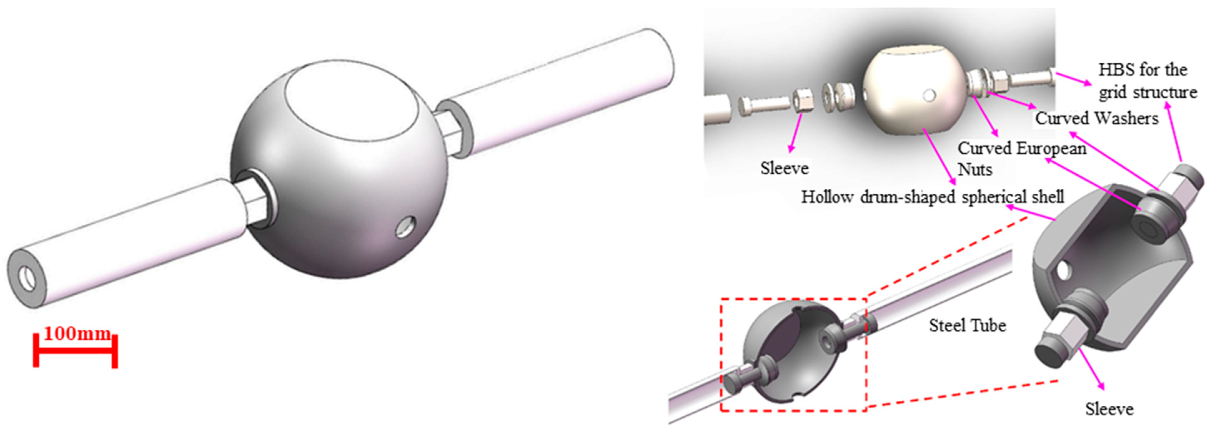
2. Structural Design of BDSSJs

2.1. Design and Functional Attributes of the Joint

The BDSSJ primarily consisted of high-strength bolts for the grid structure, sleeves, curved European nuts, curved washers, hollow drum-shaped spherical shells, and related members for grids; a detailed assembly of the joint is depicted in Figure 2. The load path aligned with that of the traditional BSJs. When members in the spatial grid were under tension, the load path was as follows: steel tube → cone/seal plate → bolt → hollow drum-shaped spherical shell → tension. Conversely, under compression, the load path was as follows: steel tube → cone/seal plate → sleeve → hollow drum-shaped spherical shell → compression.
The main innovations of this new type of BSJ include the following: (1) it combined the advantage of the efficient assembly installation of BSJs with the evident force-bearing characteristics of WHSJs; (2) the joint adopted a hollow drum shape, reducing its self-weight; (3) it can be used at the joints of buildings, site of the installation equipment, and the points supporting a roof amongst others, to achieve the advantage of saving building space.

2.2. Fabrication of the Joint

The BDSSJ can be processed based on the fabrication of welded hollow spheres, with bolt holes and installation holes set on the drum surface. The fabrication of the BDSSJ began with the cutting and forging of the materials, shaped into a hemispherical form. Attention needed to be given to the cooling rate during forging to maintain a uniform temperature. Welding then followed, involving groove welding techniques to ensure structural integrity, after which shot peening was performed to enhance the surface properties. Weld flaw detection was then carried out to ascertain the quality of the welds. Subsequently, drum surface welding was executed, followed by additional processing and shaping to refine the joint to its final form. The specimens then underwent annealing heat treatment to relieve internal stresses, followed by surface grinding to remove rust and other residues. They were, finally, coated with anti-rust oil for protection. The fabrication process is illustrated in Figure 3.

3. Experimental Investigation

3.1. Specification and Design of Specimen

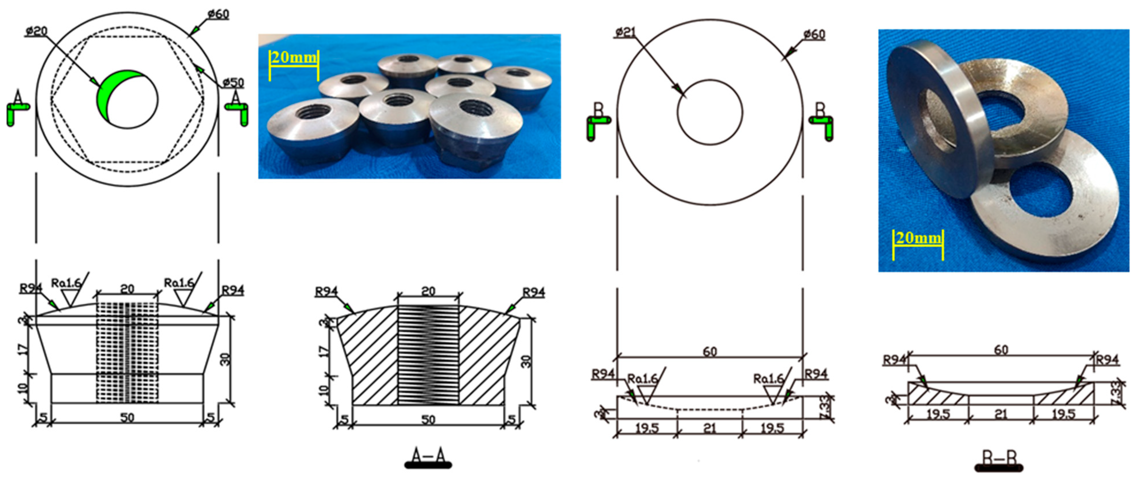
3.1.1. High-Strength Bolts and Sleeves

Based on the standard “Bolted Spherical Joints of Space Grid Structures” [25] (JGT 10-2009) and experimental conditions, this experiment used M20 high-strength bolts, with a nominal length of 73 mm and a performance grade of 10.9S. They were made of 35CrMo steel, and their threads were of regular rolling with a pitch of 2.5 mm. The surface of the bolt was treated with oxidative blackening treatment, and its effective section area was 245 mm2. The sleeves used in this experiment were selected according to “High-strength Bolts for Space Grid Bolted Spherical Joints” (GB/T 16939-2016) and were required to fit well with the M20 bolt.

3.1.2. Curved European Nuts and Curved Washers

This paper utilized curved European nuts, one end of which was cut to have a convex surface with a diameter identical to the inner diameter of the spherical shell, ensuring a tight fit; the other end was optimized to reduce the nut’s volume and weight to save steel. A single-sided spherical washer was placed between the sleeve and the shell’s connection surface, with one side milled to match the shell surface’s concave curvature. Therefore, the diameter of the spherical washer’s curvature equaled the spherical shell’s outer diameter. The detailed dimensions and actual images of the curved European nuts and curved washers are shown in Figure 4.

3.1.3. Drum-Shaped Spherical Shell

This study used the Q345B drum-shaped spherical shell, with the fabrication process outlined in Section 2.2, and detailed dimensions depicted in Figure 5.
The specimens for this experiment were assembled from high-strength bolts, curved washers, curved European nuts, and drum-shaped spherical shells. High-strength bolts were fastened through the installation holes on the drum surface. Three groups of specimens were selected for the static load axial compression test to ensure the experiment’s reliability, labeled with the serial numbers LGQ-20-1, LGQ-20-2, and LGQ-20-3, respectively.

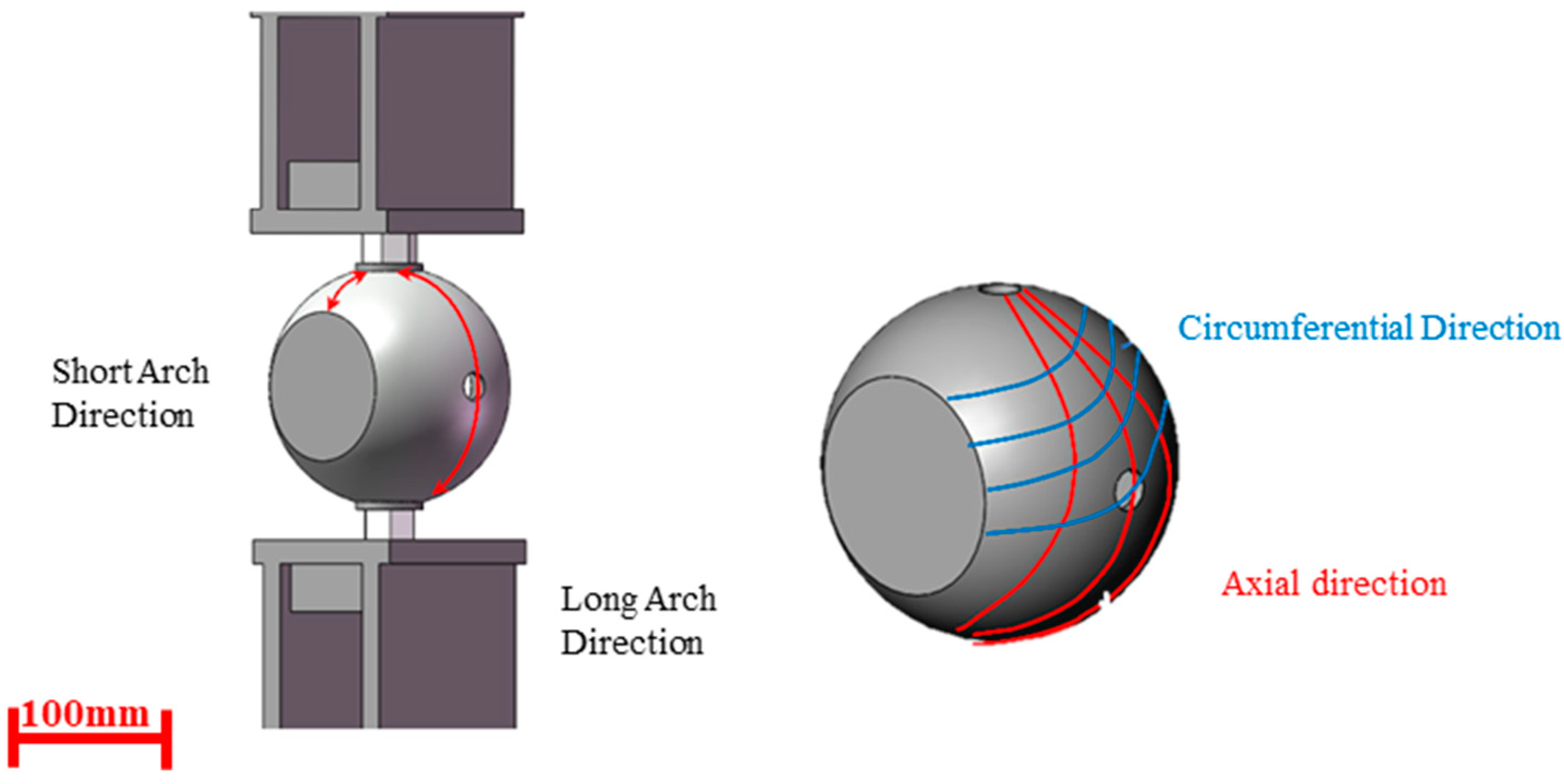
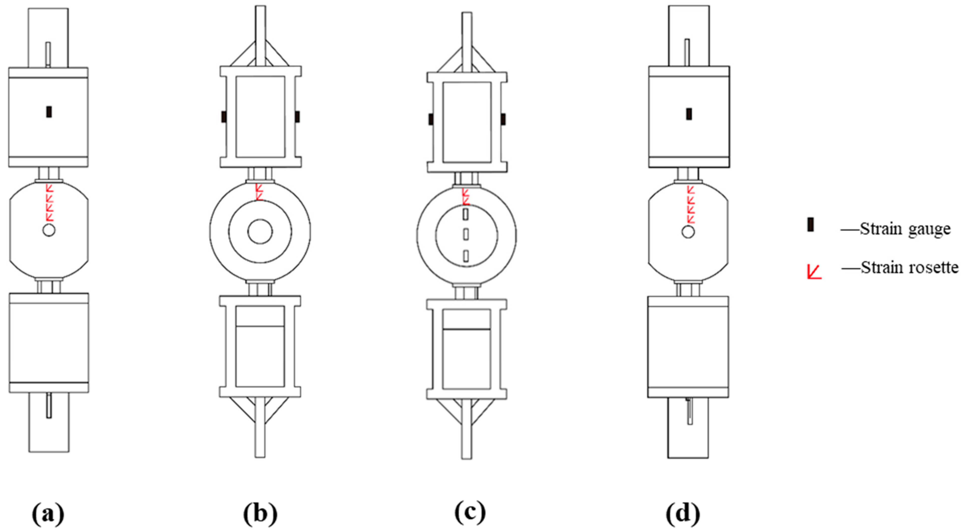
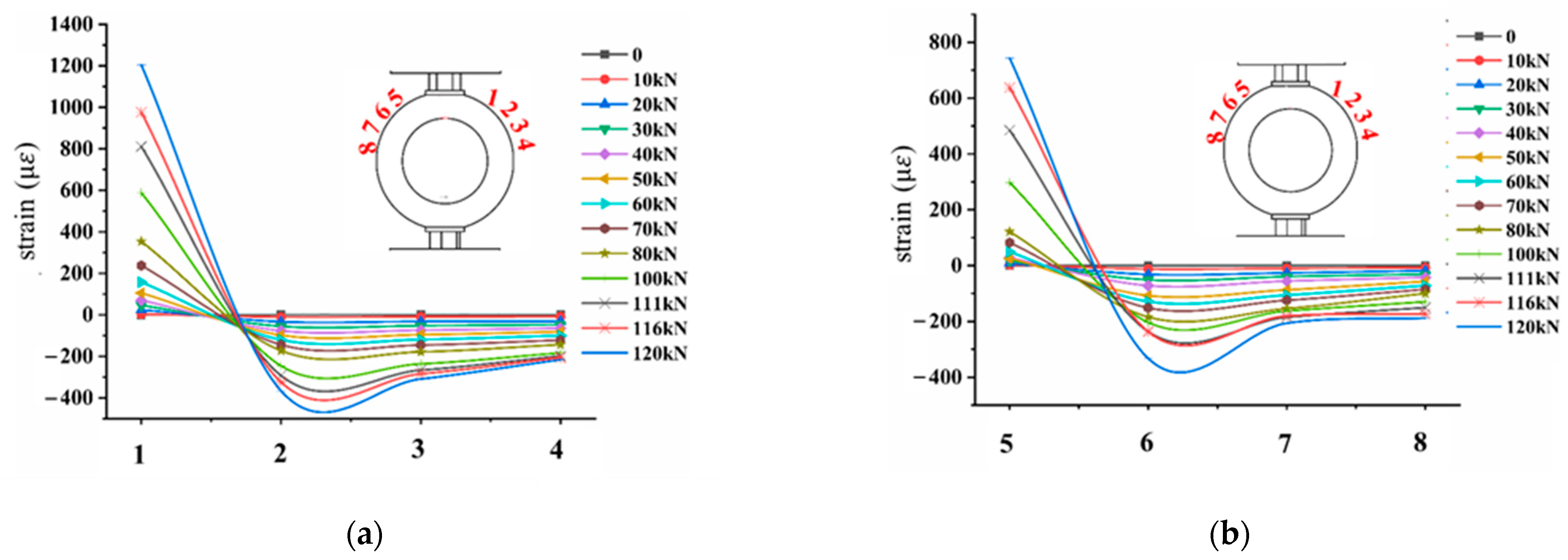
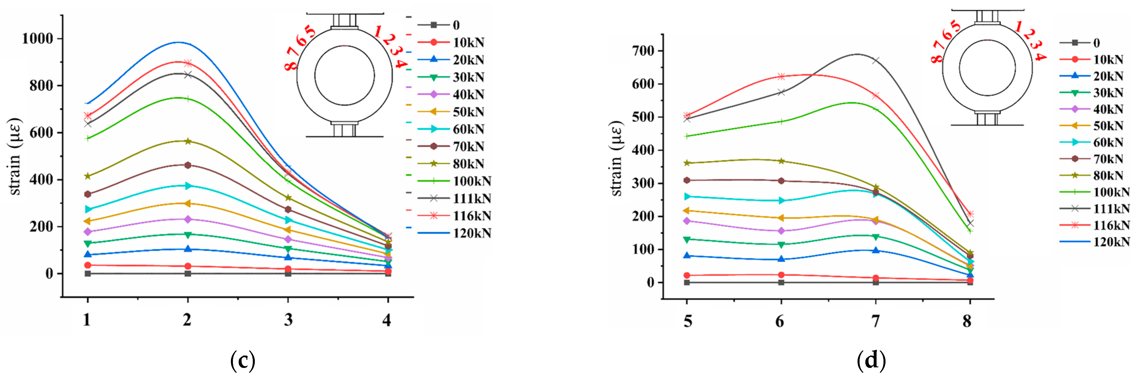
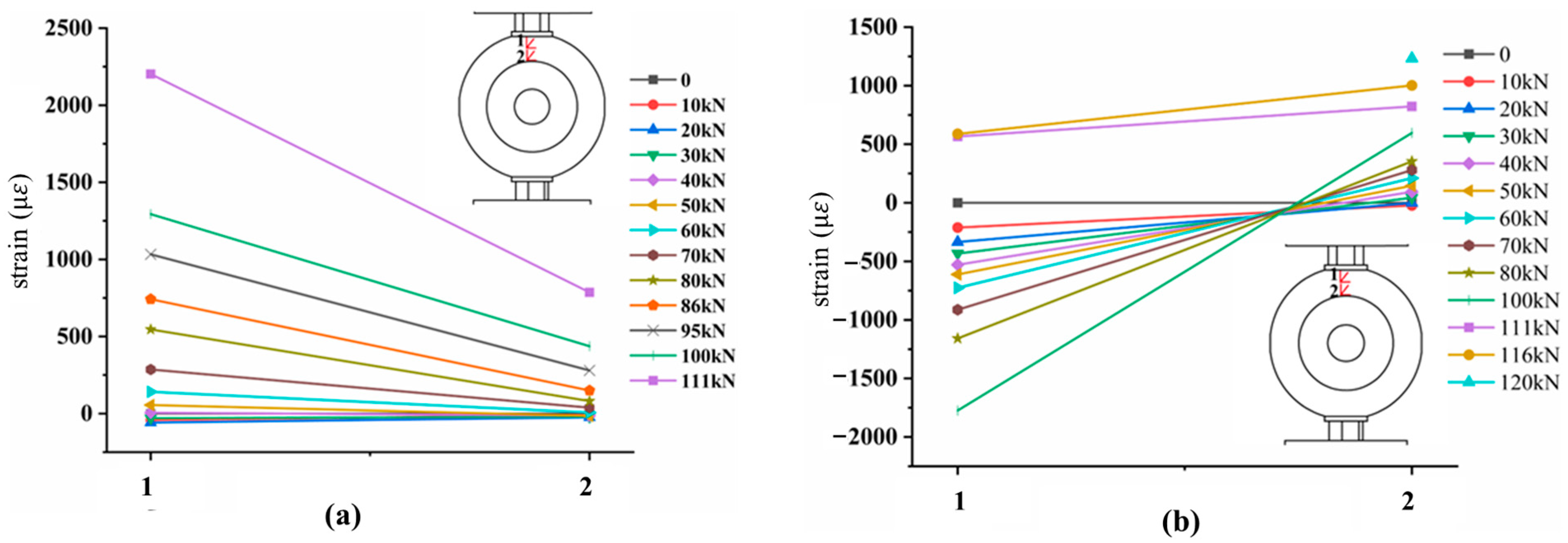
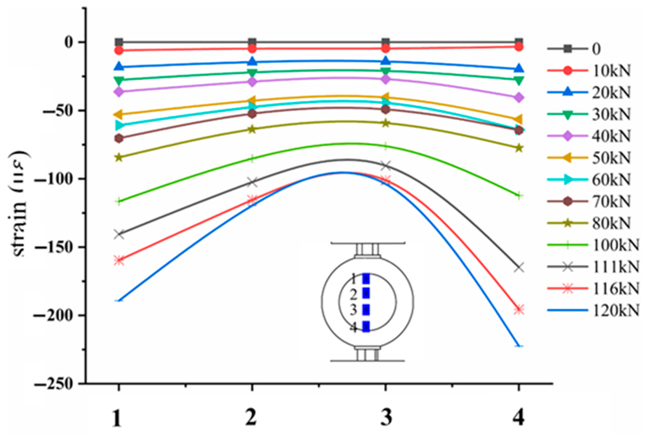
3.2. Measurement of Strain and Stress Distribution

Strain gauges were placed on the surface of the joint specimen to monitor and record strain data pertaining to the joint’s stress distribution under axial compression. The specifications of the strain gauges included a resistance value of 120 ± 0.1 Ω, and a sensitivity coefficient of 2.0 ± 1%. It was stipulated that the tangent direction of the arc line formed by the intersection of the plane perpendicular to the joint’s stress direction and the drum body was called the circumferential direction, while the tangent direction of the arc line formed by the intersection of the plane parallel to the joint’s stress direction (drum surface) and the drum body was called the axial direction. The arc surface formed between the two drum surfaces was referred to as the short arch, and the arc surface formed between two adjacent bolt holes was referred to as the long arch, as shown in Figure 6.
Four strain rosettes were placed along the centerline in the long arch direction on both sides of the loaded bolt hole, and two in the short arch direction. Four strain gauges were set on the drum surface along the stress direction. Additionally, two strain gauges were placed on both sides of the fixture at the same displacement to ensure no eccentricity in the load application. Static specimens were labeled 1–8 from left to right along the long arch, and 9–12 from front to back along the short arch, as depicted in Figure 7.

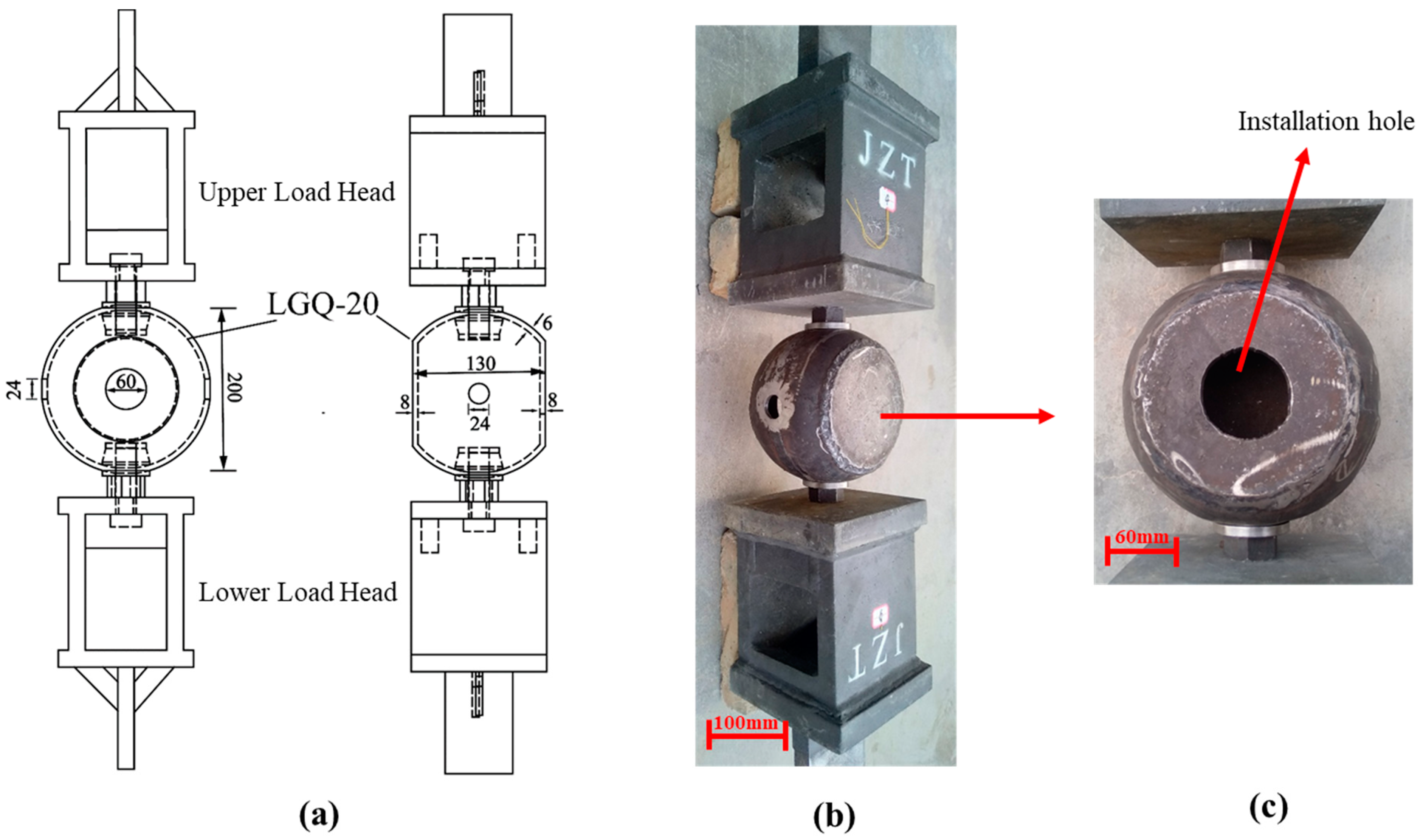
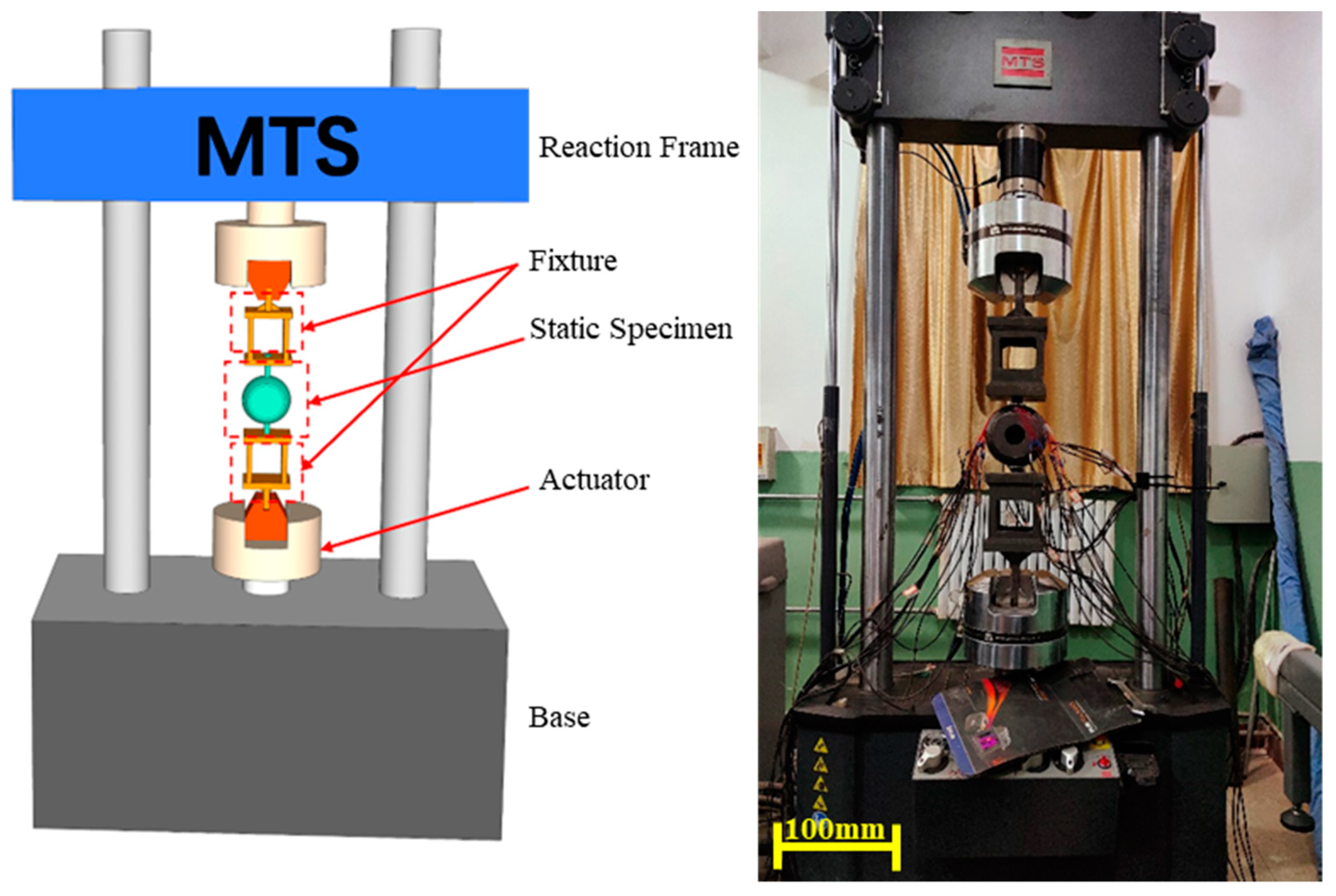
3.3. Loading Equipment and Loading Scheme

Given that the upper chord members primarily bear axial compression, a uniaxial compressive force was applied along the centerline during the experiment. The loading equipment used was an MTS fully digitized electro-hydraulic servo testing machine, with a loading range of ±500 kN, as shown in Figure 8. Before each experiment, specimens were pre-loaded to check the functionality of the measuring instruments, ensuring the load applied during pre-loading did not exceed 10% of the bearing capacity. Both load and displacement loading methods were employed during formal loading to achieve more accurate measurement results and ensure sufficient structural deformation under the load. Before the specimen yielded, the load was applied in increments of 10 kN at a rate of 5 kN/min, with each level held for 3 min. As the yield status approached, displacement-controlled loading was employed at a 0.1 mm/min rate, with each level held for 2 min. Load and axial displacement data were automatically collected by the testing machine.

3.4. Criterion for the Ultimate Load and Bearing Capacity

According to the “Criteria for Evaluation of Grid Constructional Engineering Quality Inspection” (JGJ78-91) [26] and Yu et al. [27], the criteria for determining the ultimate load of the spherical joints in the experiment could be quantitatively obtained through summarizing the experiments and FEM analysis. It is stipulated that when any one of the following situations occurs during the experiment, the joint can be considered to have reached its ultimate bearing capacity in the failure mode:
(1)
During tensile loading, when the deformation of the sphere reaches 1.2% of its diameter, the joint is considered to have reached its ultimate bearing capacity.
(2)
When the ratio of the load increment to average displacement increment in the load–displacement curve of the experiment is lower than 1%, the joint is considered to have reached its ultimate bearing capacity, taking the load applied in the previous step as the ultimate load.

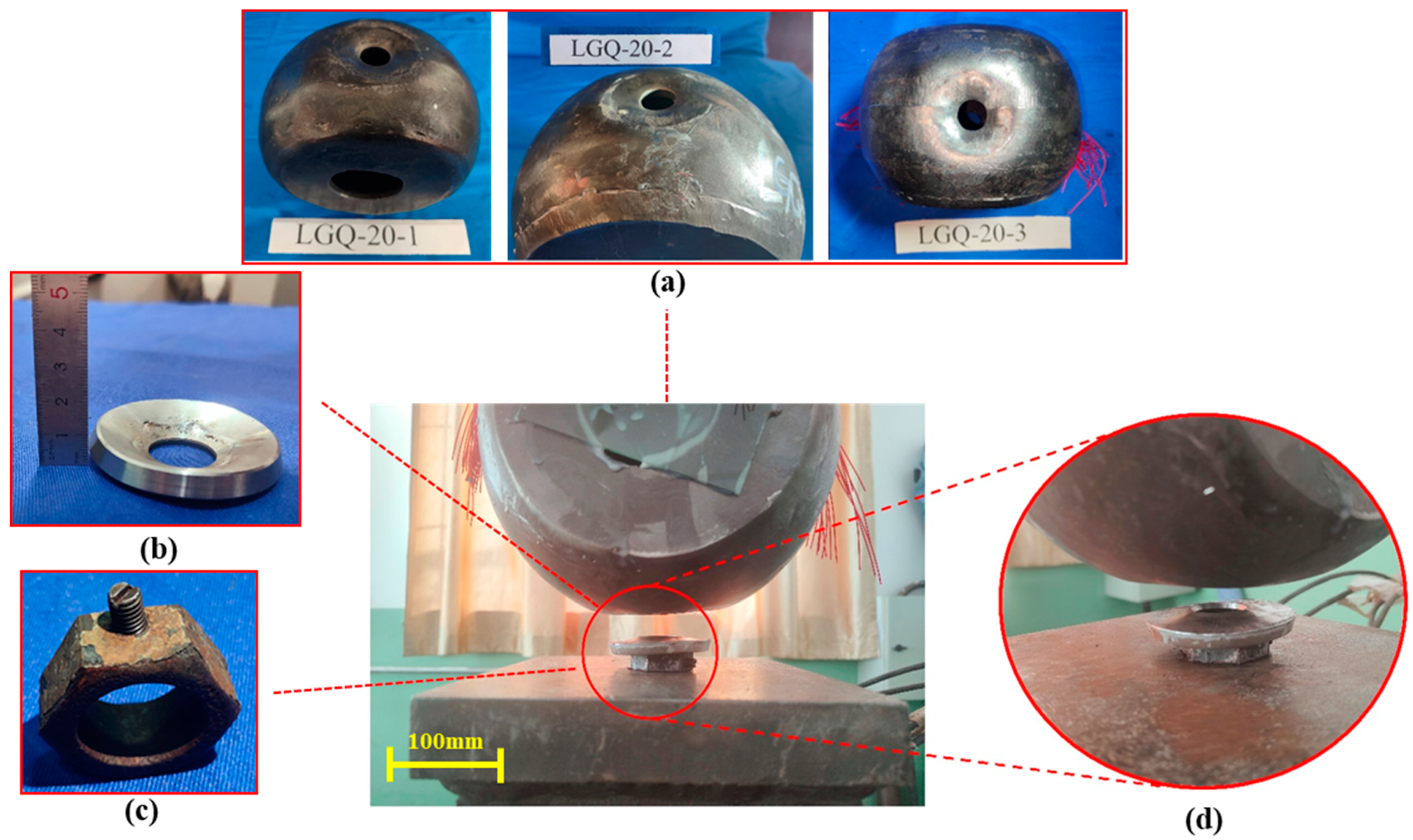
3.5. Experimental Results

Throughout the axial compression process, the specimens roughly experienced three phases: elastic phase, elastoplastic phase, and plastic phase. By continuously monitoring the load–displacement curve and the deformation of the joints, it was possible to determine whether the specimens entered the elastic or elastoplastic phases. In the early loading stage, the load and displacement increased linearly, with nearly the same deformation increment under the same load increment, exhibiting overall elastic deformation. As the load continued to increase, the curved washers gradually deformed and bent, leading to a change in the slope of the load–displacement curve. Subsequently, the loading was continued with controlled displacement, and the trend of the load–displacement curve gradually flattened, indicating that the plastic portion on the drum-shaped spherical shell expanded. At this point, the curved washers experienced significant indentation. Upon continued loading, it was observed that the load curve did not show a noticeable drop. The same static load axial compression tests were conducted on all three groups of specimens, revealing that the final failure modes were similar across all specimens, as shown in Figure 9.
Static load tests were conducted on the three groups of specimens according to the loading scheme, and the experimental data are presented in Table 1. The curves in the figure showed that as the displacement increased, the load gradually stabilized, without exhibiting a similar criterion for determining the failure mode as in welded spheres; this phenomenon has also been observed in other static load tests [28]. Throughout the test, the load did not decrease. Therefore, the maximum allowable deformation was used to determine the ultimate bearing capacity. The load sufficient to cause the local deformation of the drum body to reach 0.03 D (diameter of the drum-shaped spherical shell) was selected as the ultimate bearing capacity of the joint. The average measured diameter of the joint drum-shaped spherical shell was D = 202 mm, and the deformation under the ultimate bearing capacity was 6.06 mm, rounded to 6 mm.

4. Numerical Simulation

4.1. Finite Element Model

A three-dimensional FEM was established using the ABAQUS, a software for finite element analysis, with the model size identical to the actual specimens’ size. The model was entirely constructed using C3D8R elements, ignoring welding defects and heterogeneities. The load transmission path under the axial compression of the joint is as follows: steel tube → cone/seal plate → sleeve → hollow drum-shaped spherical shell. Therefore, when simulating the compression of the node, only the curved washer, sleeve, and drum-shaped node need to be modeled. The drum-shaped hollow spherical shell was of specification Q345B, with the same material used for the sleeves and bolts. The curved washer and curved nut were modeled using quenched 45# steel. A reinforced elastoplastic bilinear model was used for Q345B, while an ideal elastoplastic bilinear model was used for 45# steel. The elastic modulus (E) was taken as 210 GPa, with a Poisson’s ratio of 0.3. The yield strength for Q345 was 345 MPa, with an ultimate strength of 480 MPa; the yield strength for 45# steel was 420 MPa. The constitutive models for these materials are illustrated in Figure 10 below.
The joint was compressed uniformly downward through the loading fixture in the actual loading process. To simplify the calculation, reference points RP-1 and RP-2 were set on the sleeve surface in a coupled manner in the model. RP-1 was used as the loading point through displacement for load application, while RP-2 was the reference point for boundary constraints, subject to fixed constraints. In this model, the grid size for the wall thickness was divided into three layers, each about 2~3 mm. In this model with fewer component types, structured mesh division could be conducted for the curved washers and curved European nuts, while swept mesh division was performed on the drum-shaped spherical shell to minimize grid distortion. Friction contact was set between the sleeve’s bottom surface and the curved washer’s contact surface, and between the curved washer and the surface of the drum-shaped shell. The normal contact was set to be “hard”, allowing separation after surface-to-surface contact; the tangential friction coefficient was set as 0.2, as shown in Figure 11. The finite element simulation load matches the experimental load.

4.2. Simulation Results

Under the axial compressive load, the BDSSJs underwent certain plastic deformation, and were determined to have reached the ultimate bearing capacity due to excessive deformation. During the loading process, the joint underwent elastic deformation, elastoplastic development, and the local indentation of the drum body. The three main phases of the axial compressive failure mode are shown in Figure 12 below, and the load–displacement curve is given in Figure 13.
In the first stage, the load–displacement curve of the joint showed linear growth during the loading process. The stress at the bolt holes of the drum body gradually increased, pushing this part into the yield status first, while other sections were far below the material’s yield strength, remaining in the elastic phase. The loaded bolt holes had no obvious deformation, as shown in Figure 12a.
In the second stage, the area entering the plastic phase near the loaded bolt holes gradually enlarged with the continuous load increase. The inner surface of the drum-shaped shell near the loaded area joined the yield status. As the load gradually increased, the area of the yield status on the inner and outer surfaces continually spread, initiating a stress redistribution process in the shell joint; the load–displacement curve showed nonlinear growth, as shown in Figure 12b.
In the third stage, an indentation occurred at the loaded bolt holes. During this phase, a wide range of plastic zones appeared in the curved washer and drum-shaped shell, leading to certain plastic deformation. The non-loaded bolt holes and the cover plate areas did not yield. The indented deformation intensified with the increase in loading displacement, as depicted in Figure 12c.
Moreover, throughout the loading process, the curved washer gradually underwent plastic deformation, and the bottom of the sleeve became warped, featuring plastic deformation. Upon reaching the ultimate load, a large area of the drum body at the loaded bolt holes yielded, locally forming a through-thickness area of plastic penetration. Upon further loading, the load drop was not sharp, but the excessive joint deformation led to the eventual failure of the joint.

5. Discussion

5.1. Analysis of the Ultimate Bearing Capacity

From Table 1, it can be deduced that before the load reached 90 kN, the displacement increment under every 10 kN load increment was around 0.3 mm. With the load exceeding 90 kN, the joint entered the elastoplastic stage, with uneven growth in the displacement increment. With 6mm as the deformation of the joint under the ultimate load, the ultimate bearing capacity of the static specimens is shown in Table 2 below:
Luo [29] has carried out numerical analyses on this type of joint and derived the corresponding formula for the joint’s bearing capacity:
N R c = 250.66 × T e + 18005.56 T 2 e 2 D 2
Note: D is the outer diameter of the spherical shell; e represents the diameter of the curved washer; and T stands for the wall thickness of the spherical shell.
By inserting the parameters of the joint from the experiment (T = 6 mm, D = 200 mm, e = 60 mm) into the previously mentioned formula, a result of a theoretical bearing capacity was obtained ( N R c = 148.57 kN). When compared with the average value obtained from the three experiments, it was found that the theoretical value was higher. A parameter η was introduced to align the theoretical bearing capacity formula more closely with the experimental results. By applying this parameter, a more accurate estimation of the compressive bearing capacity of the BDSSJ can be achieved. The modified formula is as follows, with the value of η being 0.78:
N R c = η 250.66 × T e + 18005.56 T 2 e 2 D 2

5.2. Analysis of the Strain and Stress Distribution

The stress distribution of the drum-shaped spherical shell could be provided by strain gauges attached to the shell. While stress can be deduced from strain during small deformations, the relationship became nonlinear as more significant deformations pushed the joint into the plastic phase. Hence, strain was used as the target parameter for the stress distribution analysis. The results are illustrated in Figure 14.
The test results indicated that on the long arch of the drum body, the axial strain gradually decreased from the edge of the curved washer to the non-loaded bolt hole, and then changed reversely with a gradual increase. The maximum strain occurred in the influence zone of the curved washer edge, while the minimum strain occurred at the non-loaded bolt hole. During this period, the strain changed from tensile to compressive strain. On the long arch of the drum body, the circumferential strain at all eight points was tensile, indicating tension; the strain exhibited a trend of first increasing and then decreasing, with all the strains not exceeding the yield point. The similarity in the trend of the axial and circumferential strain variation curves on the long arches on both sides of the drum body, albeit with different peak values, demonstrated reliability in the experimental data. On the other hand, it suggested that there might be uneven stress distribution when the BDSSJ was under load. This unevenness may also be related to the uniformity of the wall thickness and welding performance during the specimen fabrication.
The analysis of the axial and circumferential strain data on the short arches of the drum body revealed that the axial strain at the edge of the curved washer increased with the growing load, entering the yield status with a load of around 100 kN. The axial strain across the short arches was all tensile. The circumferential strain near the curved washer edge gradually increased with the load, and the strain abruptly transitioned from compressive to tensile when the load exceeded 100 kN. The intersection of the drum body on the short arches with the cover plate experienced minimal stress, with all stress remaining within the elastic range, as illustrated in Figure 15
Measurements were also conducted on the stress changes in the cover plate under axial compression. Four strain gauges were evenly attached to the cover plate from top to bottom, and the results are shown in the above figure. It was found that the cover plate was under compressive stress during the loading process, and the stresses were relatively small, far below the material’s yield strength. The ends of the cover plate experienced higher stress compared to the middle. As the load increased, the compressive strain on the cover plate slowly increased, indicating a significant reserve of strength, as illustrated in Figure 16.

6. Conclusions

Based on the axial compression tests and numerical research on the BDSSJs, the following conclusions could be drawn:
(1)
No significant drop occurred in the load–displacement curve obtained from the experiment on the BDSSJs. According to the maximum allowable deformation, the joint’s ultimate bearing capacity could be calculated as the load value that caused the local deformation value to reach 3% of the outer diameter of the drum-shaped spherical shell.
(2)
Static load axial compression tests were carried out on the BDSSJ specimen LGQ-20, and the ultimate bearing capacity of the joint was found to be 116 kN.
(3)
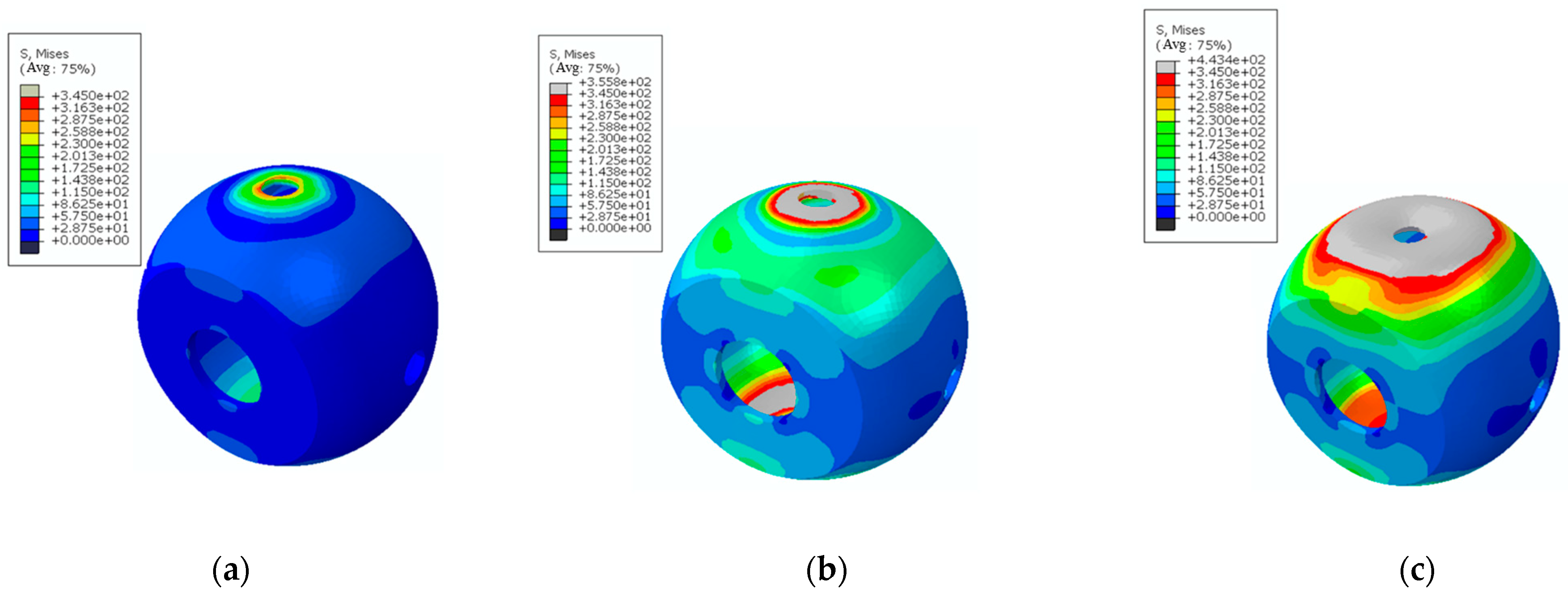
Under the axial compression load, both the inner and outer surfaces of the shell within the range of the curved washer were in a compressed state, with the stress being the lowest at the non-loaded bolt holes. The outer surface of the shell’s long arch in the axial direction showed compression between the curved washer and non-loaded bolt holes area, while the inner surface exhibited tension. The cover plate was in a compressed state, and its stress level was significantly below the material’s yield strength.
(4)
The FEM analysis revealed that the failure process of the joint under unidirectional axial compression could be divided into three stages. The first stage was the elastic stage, during which a small area near the loaded bolt holes yielded, but the shell as a whole remained elastic. The second stage was the elastoplastic deformation stage, where the plastic area at the bolt holes enlarged and the inner surface of the shell yielded. In the third stage, significant indentation occurred at the loaded bolt holes, and the joint deformation tended towards a limiting value.

Author Contributions

Conceptualization, Y.Y.; methodology, Y.Y. and Z.Z.; software, Y.Y. and X.M.; validation, M.L.; formal analysis, Y.Y. and X.M.; investigation, M.L.; resources, M.L.; data curation, Y.Y. and Z.Z.; writing—original draft preparation, Y.Y. and Z.Z.; writing—review and editing, Y.Y., Z.Z., M.L. and X.M.; visualization, Y.Y. and Z.Z.; supervision, M.L. and Z.Z.; project administration, Z.Z.; funding acquisition, Y.Y. and X.M. All authors have read and agreed to the published version of the manuscript.

Funding

This research was funded by the National Nature Science Foundation of China, grant number No. 51178286.

Institutional Review Board Statement

Not applicable.

Informed Consent Statement

Not applicable.

Data Availability Statement

All data generated or analyzed in this research were included in this published article. Additionally, readers can access all data used to support the conclusions of the current study from the corresponding author upon request.

Conflicts of Interest

M.L. was employed by Shanxi 6th Construction Group Co., Ltd. The remaining authors declare that the research was conducted in the absence of any commercial or financial relationships that could be construed as a potential conflict of interest.

References

  1. Caglayan, O.; Yuksel, E. Experimental and Finite Element Investigations on the Collapse of a Mero Space Truss Roof Structure—A Case Study. Eng. Fail. Anal. 2008, 15, 458–470. [Google Scholar] [CrossRef]
  2. Ebadi Jamkhaneh, M.; Davoodi, M.R.; Ebadi Jamkhaneh, J. Assessment of the Ball Joint Behavior under Combine Loading. Modares Civ. Eng. J. 2017, 17, 149–159. [Google Scholar]
  3. Ghasemi, M.; Davoodi, M.R.; Mostafavia, S.A. Tensile Stiffness of MERO-Type Connector Regarding Bolt Tightness. J. Appl. Sci. 2010, 10, 724–730. [Google Scholar] [CrossRef]
  4. Doaei, Y.; Aghakouchaki Hosseini, S.E.; Momenzadeh, A.; Harirchian, E. Investigating the Effect of Screw Size on the Stress Level in MERO Joint for Space Frame Structures. Appl. Syst. Innov. 2021, 4, 84. [Google Scholar] [CrossRef]
  5. Xu, J.; Wang, C.; Li, H.; Zhang, C.; Hao, J.; Fan, S. Health Monitoring of Bolted Spherical Joint Connection Based on Active Sensing Technique Using Piezoceramic Transducers. Sensors 2018, 18, 1727. [Google Scholar] [CrossRef]
  6. Fan, F.; Ma, H.; Chen, G.; Shen, S. Experimental Study of Semi-Rigid Joint Systems Subjected to Bending with and without Axial Force. J. Constr. Steel Res. 2012, 68, 126–137. [Google Scholar] [CrossRef]
  7. Si, Q.; Tang, Y.; Zong, L.; Liu, H.; Kang, B. Experimental Study and Numerical Simulation of the Tensile Properties of Corroded Bolt-Sphere Joints. Buildings 2022, 12, 1989. [Google Scholar] [CrossRef]
  8. Ding, B.; Zhao, Y.; Huang, Z.; Cai, L.; Wang, N. Tensile Bearing Capacity for Bolted Spherical Joints with Different Screwing Depths of High-Strength Bolts. Eng. Struct. 2020, 225, 111255. [Google Scholar] [CrossRef]
  9. Yang, D.; Li, M.; Fu, F.; Wu, J. Experimental and Numerical Studies on a New Type of Bolt-Ball Joint for Spatial Grid Structures. J. Constr. Steel Res. 2022, 188, 107035. [Google Scholar] [CrossRef]
  10. Huang, B.; Lu, M.; Fu, Y.; Yang, F. Experimental Investigation on Tensile Properties of the Bolt in Sphere Joints Under Fire. Int. J. Steel Struct. 2020, 20, 1355–1363. [Google Scholar] [CrossRef]
  11. Tian, J.; Wang, X.; Li, H.; Wang, Z.; Pan, J. Ultra-Low Cycle Fatigue Performance of Grid Structure with Bolted Spherical Joints. J. Constr. Steel Res. 2023, 201, 107728. [Google Scholar] [CrossRef]
  12. Yang, X.; Lei, H.; Chen, Y.F. Constant Amplitude Fatigue Test Research on M20 High-Strength Bolts in Grid Structure with Bolt–Sphere Joints. Adv. Struct. Eng. 2017, 20, 1466–1475. [Google Scholar] [CrossRef]
  13. Qiu, B.; Yang, X.; Zhou, Z.; Lei, H. Experimental Study on Fatigue Performance of M30 High-Strength Bolts in Bolted Spherical Joints of Grid Structures. Eng. Struct. 2020, 205, 110123. [Google Scholar] [CrossRef]
  14. Zhou, Z.; Lei, H.; Qiu, B.; Zhang, S.; Wang, G. Experimental Study on Fatigue Performance of M60 High-Strength Bolts with a Huge Diameter under Constant Amplitude Applied in Bolt–Sphere Joints of Grid Structures. Appl. Sci. 2022, 12, 8639. [Google Scholar] [CrossRef]
  15. Fernández Landeta, J.; Fernández Valdivielso, A.; López De Lacalle, L.N.; Girot, F.; Pérez Pérez, J.M. Wear of Form Taps in Threading of Steel Cold Forged Parts. J. Manuf. Sci. Eng. 2015, 137, 031002. [Google Scholar] [CrossRef]
  16. Bustillo, A.; Urbikain, G.; Perez, J.M.; Pereira, O.M.; Lopez de Lacalle, L.N. Smart Optimization of a Friction-Drilling Process Based on Boosting Ensembles. J. Manuf. Syst. 2018, 48, 108–121. [Google Scholar] [CrossRef]
  17. Xing, J.; Qiu, C.; Wang, M.; Yang, N. Uniaxial Failure Mechanism and Design Strength of High-Strength Welded Hollow Spherical Joint. Eng. Struct. 2022, 256, 113897. [Google Scholar] [CrossRef]
  18. Liu, H.; Ying, J.; Chen, Z.; Zhou, Y.; Yan, X. Ultimate Tensile and Compressive Performances of Welded Hollow Spherical Joints with H-Beam. J. Constr. Steel Res. 2018, 150, 195–208. [Google Scholar] [CrossRef]
  19. Zhang, J.; Lei, H.; Jin, S. Experimental Study on Constant-Amplitude Fatigue Performance of Weld Toe in Steel Tube of Welded Hollow Spherical Joints in Grid Structures. Adv. Mater. Sci. Eng. 2019, 2019, 6204302. [Google Scholar] [CrossRef]
  20. Duan, Y.; Lei, H.; Jin, S. Experimental Study on Fatigue Performance of Welded Hollow Spherical Joints Reinforced by CFRP. Coatings 2022, 12, 1585. [Google Scholar] [CrossRef]
  21. Yan, R.; Yu, Z.; Wang, S.; Liu, J. Influence of Welding Residual Stress on Bending Resistance of Hollow Spherical Joints. J. Constr. Steel Res. 2023, 208, 108004. [Google Scholar] [CrossRef]
  22. Zhao, Z.; Dai, B.; Xu, H.; Li, T. Bending Capacity of Corroded Welded Hollow Spherical Joints with Considering Interaction of Tension Force and Bending Moment. Structures 2021, 34, 2656–2664. [Google Scholar] [CrossRef]
  23. Huang, B.; Lu, M.; Cao, Y.; Yang, F. Experimental Study on Residual Performance of Welded Hollow Spherical Joints Subjected to Axial Compression after a Fire. Structures 2021, 30, 996–1005. [Google Scholar] [CrossRef]
  24. Shu, T.; Xu, X.; Pan, W.; Huang, W.; Luo, Y. Compressive Performance of Welded Hollow Spherical Joints with External Triangular Ribs. Eng. Struct. 2023, 280, 115717. [Google Scholar] [CrossRef]
  25. JG/T 10-2009; Bolted Spherical Node of Space Grid Structures. China Architecture and Building Press: Beijing, China, 2009.
  26. JGJ78-91; Criteria for Evaluation of Grid Constructional Engineering Quality Inspection. Architecture & Building Press: Beijing, China, 1991.
  27. Yu, K.; Yu, J.; Tang, B. Experimental and finite element analysis of the ultimate bearing capacity of hollow sphericl joints with ribbd stiffener. Ind. Constr. 2011, 41, 85–90. [Google Scholar] [CrossRef]
  28. Liu, Y.; Fan, J.; Liu, Z.; Jiao, J.; Lei, H. Finite element analysis of the influence of detailed structural measures on static performance of complex tubular joints. J. Taiyuan Univ. Technol. 2022, 53, 149–155. [Google Scholar] [CrossRef]
  29. Luo, C. Design and Analysis of Round Steel Tube Supporting Assembly Nodes. Master’s Thesis, Taiyuan University of Technology, Taiyuan, China, 2019. [Google Scholar]
Figure 1. Typical joint types in space grid structures: (a) bolted spherical joint and (b) welded hollow spherical joint.
Coatings 14 00229 g001
Figure 2. Bolted drum spherical shell joint.
Coatings 14 00229 g002
Figure 3. The fabrication process of the BDSSJ: (a) cutting, (b) forging and shaping, (c) hemispherical surface processing, (d) welding and shaping, (e) shot peening, (f) weld flaw detection, (g) drum surface welding, (h) processing, shaping, and treatment.
Coatings 14 00229 g003
Figure 4. Curved European nuts and curved washers (unit: mm).
Coatings 14 00229 g004
Figure 5. Schematic diagram of specimens: (a) dimensions and details of specimens (unit: mm), (b) picture of specimens, (c) installation hole.
Coatings 14 00229 g005
Figure 6. Schematic diagram of different directions of the joint.
Coatings 14 00229 g006
Figure 7. The layout of the strain measurement points: (a) left view; (b) front view; (c) rear view; (d) right view.
Coatings 14 00229 g007
Figure 8. Diagram of the loading equipment for the static load test.
Coatings 14 00229 g008
Figure 9. Final failure mode of the specimen: (a) hollow drum-shaped spherical shell deformation diagram, (b) curved washer deformation diagram, (c) sleeve deformation diagram, (d) failure modes.
Coatings 14 00229 g009
Figure 10. The models for different materials: (a) Q345B; (b) 45# steel.
Coatings 14 00229 g010
Figure 11. The FEM: (a) the overall model, (b) the model with mesh division.
Coatings 14 00229 g011
Figure 12. The phases of the BDSSJ’s failure mode: (a) stress cloud diagram of elastic stage, (b) stress cloud diagram of plastic development stage, (c) stress cloud diagram of local depression stage.
Coatings 14 00229 g012
Figure 13. The load–displacement curve of the BDSSJ (a: elastic stage, b: plastic development stage, c: local depression stage).
Coatings 14 00229 g013
Figure 14. Strain diagram in the direction of the long arch of the drum body of LGQ-20-1: (a) axial strain of strain gauges No. 1–4; (b) axial strain of strain gauges No. 5–8; (c) circumferential strain of strain gauges No. 1–4; (d) circumferential strain of strain gauges No. 5–8.
Coatings 14 00229 g014aCoatings 14 00229 g014b
Figure 15. Circumferential and axial strain diagram in the direction of the short arch of the drum body of LGQ-20-1: (a) circumferential strain diagram; (b) axial strain diagram.
Coatings 14 00229 g015
Figure 16. Strain diagram of the cover plate of LGQ-20-1.
Coatings 14 00229 g016
Table 1. Experimental data for the load–displacement curve.
LGQ-20-1LGQ-20-2LGQ-20-3
Load (kN)Displacement (mm)Displacement Increment (mm)Load (kN)Displacement (mm)Displacement Increment (mm)Load (kN)Displacement (mm)Displacement Increment (mm)
100.60 100.46 100.54
201.150.55200.740.28200.830.29
301.550.4300.990.25301.140.31
401.860.31401.180.19401.490.35
502.100.24501.390.21501.90.41
702.710.31701.850.24702.480.3
803.000.31802.170.32802.840.36
903.440.44902.460.29903.270.43
1004.010.571002.870.411004.020.75
1104.880.871103.590.721105.741.68
1207.402.521205.251.6612011.375.63
12513.526.121256.761.5112516.805.43
13021.47.8813419.9913.2312819.993.19
Table 2. Bearing capacity results of BDSSJs.
Serial No.Specimen IDDeformation (mm)Measured Ultimate Bearing Capacity (kN)Average (kN)Relative Deviation
1LGQ-20-16116.22116.670.38%
2LGQ-20-26122.774.97%
3LGQ-20-36111.005.1%
Disclaimer/Publisher’s Note: The statements, opinions and data contained in all publications are solely those of the individual author(s) and contributor(s) and not of MDPI and/or the editor(s). MDPI and/or the editor(s) disclaim responsibility for any injury to people or property resulting from any ideas, methods, instructions or products referred to in the content.

