
Reliability Evaluation of a Dynamic-Pressure Mechanical Seal Based on Liquid Film Vaporization Phase Transition

Abstract
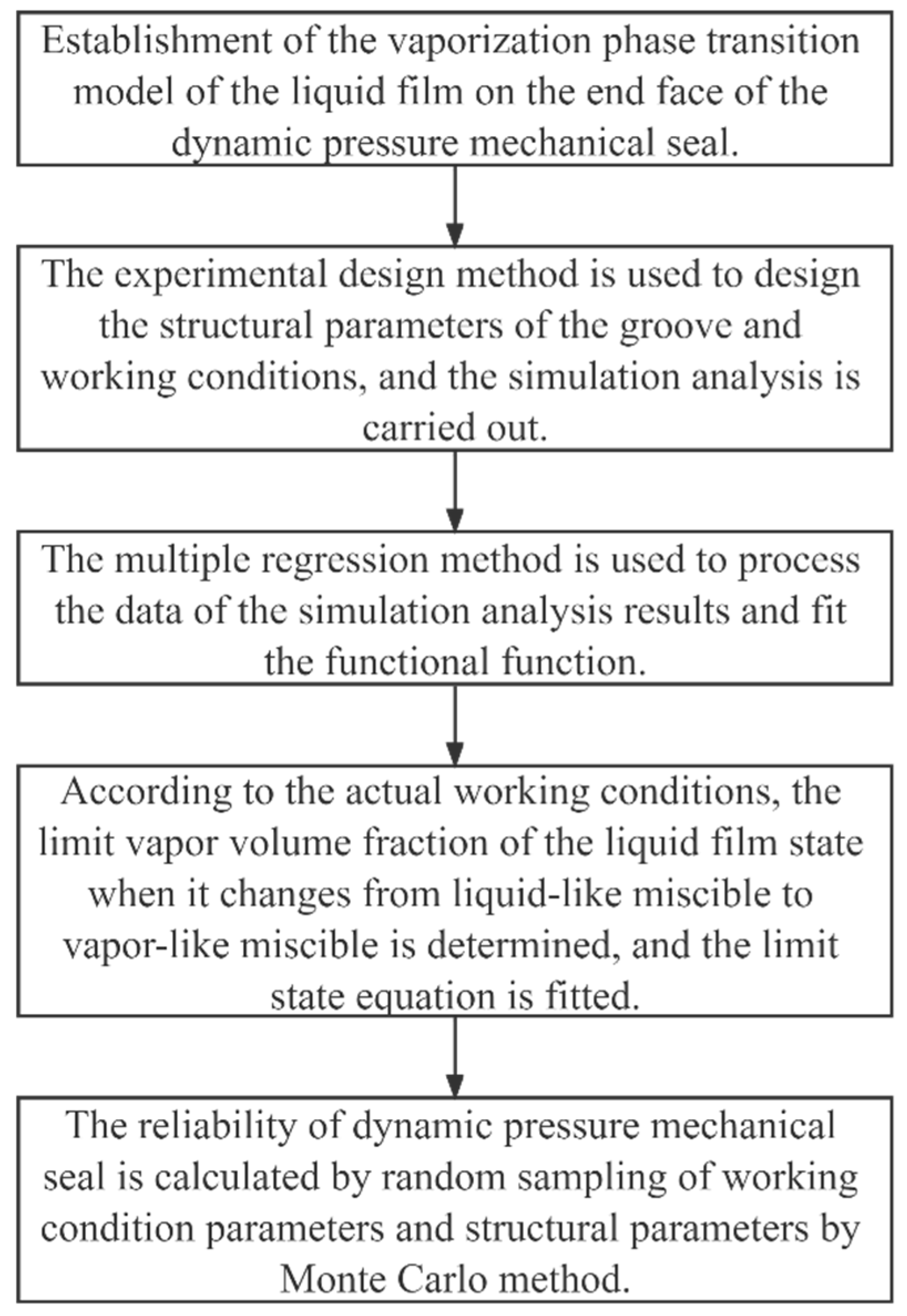
:1. Introduction
2. Vaporization-Phase Transition Model
2.1. Theoretical Analysis
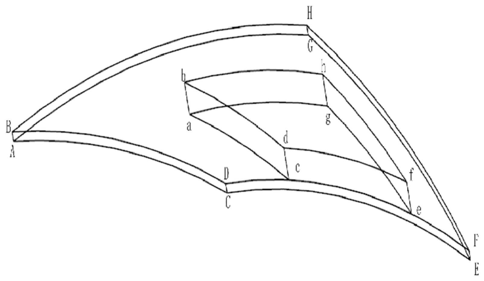
2.2. Geometric Model
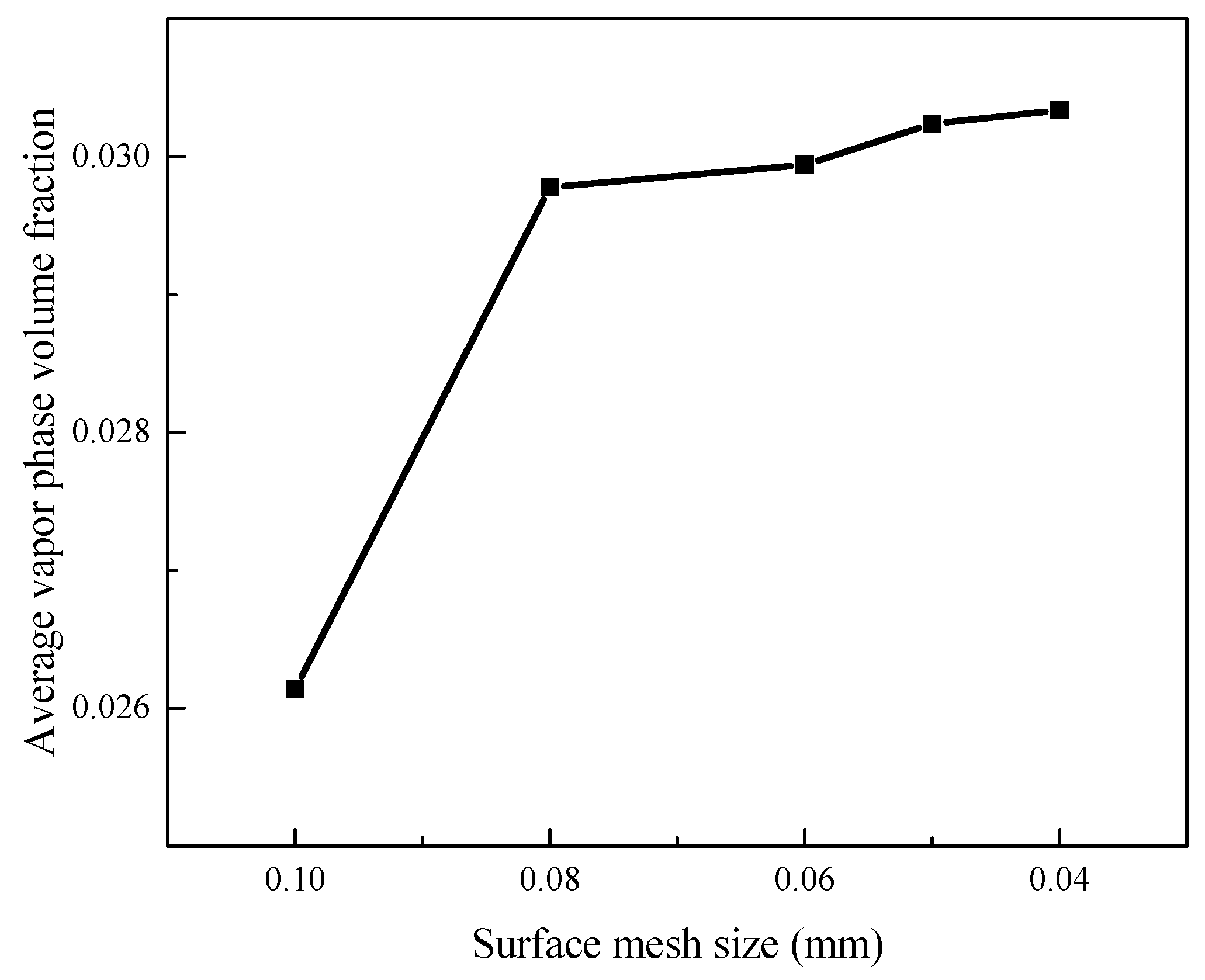
2.3. Meshing
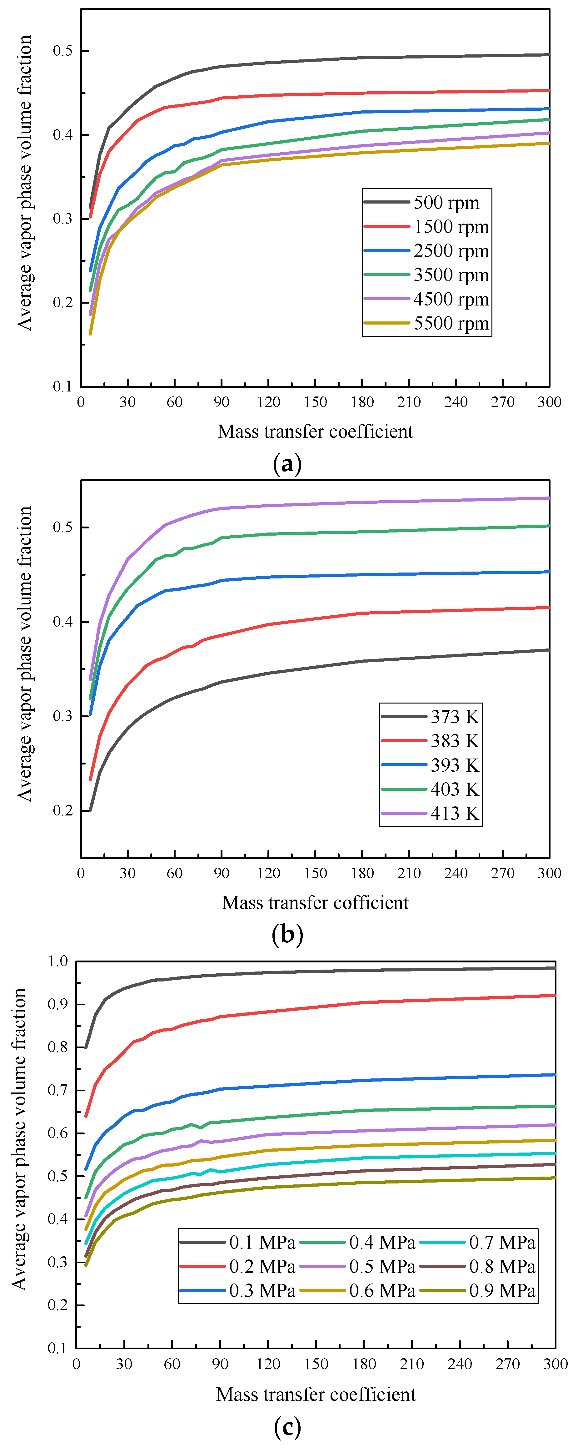
2.4. Solver Settings
3. Limit State Equation Establishment
3.1. The Function
3.2. Limit State Equation
4. Reliability Evaluation Based on Liquid Film Vaporization Phase Transition
4.1. Reliability Evaluation and Assessment
4.2. Case Study Application
5. Conclusions
Author Contributions
Funding
Institutional Review Board Statement
Informed Consent Statement
Data Availability Statement
Acknowledgments
Conflicts of Interest
References
- He, J.C.; Li, D.P. Analysing dependaency of mechanical seal face seal. Coal Mine Mach. 2003, 7, 36–37. [Google Scholar]
- Ojile, J.O.; Teixeira, J.A.; Carmody, C. Mechanical Seal Failure Analysis. Tribol. Trans. 2010, 53, 630–635. [Google Scholar] [CrossRef]
- Zhou, J.F.; Gu, B.Q. Reliability estmiation of mechanical seal based on Monte Carlo Smiulation. Lubr. Eng. 2006, 2, 102–104 + 135. [Google Scholar]
- Wei, L.; Sun, J.J. Analysis of the reliability of mechanical seal. Energy Chem. Ind. 2002, 3, 16–18 + 1. [Google Scholar]
- Wei, L.; Gu, B.Q.; Sun, J.J.; Feng, X. Parameter estimation of reliability of mechanical seal for petrochemical pump. Fluid Mach. 2008, 2, 27–30. [Google Scholar]
- Hao, Y.J.; Gu, B.Q. Fuzzy comprehensive evaluation method for mechanical seal risk assessment of centrifugal pumps. In International Conference on Advanced Materials and Computer Science; Intelligent Information Technology Application Association, Proceedings of 2011 International Conference on Advanced Materials and Computer Science (ICAMCS 2011 Part2); TRANS TECH PUBLICATIONS: Stafa-Zurich, Switzerland, 2011; pp. 474–476, 1283–1287. [Google Scholar]
- Liao, C.J.; Huang, W.F.; Wang, Y.M.; Suo, S.F.; Liu, X.F. Optimization design for mechanical seals in reactor coolant pumps based on a fluid-solid strong-interaction model. Proc. Inst. Mech. Eng. Part C J. Mech. Eng. Sci. 2011, 225, 1851–1862. [Google Scholar] [CrossRef]
- Chen, R.T.; Zhang, C.; Wang, S.P.; Qian, Y.J. Reliability estimation of mechanical seals based on bivariate dependence analysis and considering model uncertainty. Chin. J. Aeronaut. 2021, 34, 554–572. [Google Scholar] [CrossRef]
- Li, L.Y. Research on the Reliability of the Key Components of the Domestical Large-Scale Pump. Master’s Thesis, China University of Petroleum, Beijing, China, 2016. [Google Scholar]
- Hughes, W.F.; Chao, N.H. Phase change in liquid face seals II—Isothermal and adiabatic bounds with real fluids. J. Lubr. Technol. 1980, 102, 350–357. [Google Scholar] [CrossRef]
- Yang, X.; Meng, X.K.; Peng, X.D. A TEHD lubrication analysis of surface textured mechanical seals. Tribology 2018, 38, 204–212. [Google Scholar]
- Li, F.C.; Wang, Y.L.; Liu, J.; Ding, S.Y.; Li, X. Analysis and study on failure mechanism of mechanical seals in running. Hydraul. Pneum. Seals 2019, 39, 46–49. [Google Scholar]
- Zhang, X.; Shi, J.; Wang, S.; Zhang, C.; Tomovic, M. Leakage model and failure factors analysis of mechanical seals. In Proceedings of the 2016 IEEE 11th Conference on Industrial Electronics and Applications (ICIEA), Hefei, China, 5–7 June 2016. [Google Scholar]
- Gu, Y.Q. Mechanical Seal Practical Technology; China Machine Press: Beijing, China, 2001. [Google Scholar]
- Lee, H.; Agonafer, D.D.; Won, Y.; Houshmand, F.; Gorle, C.; Asheghi, M.; Goodson, K.E. Thermal modeling of extreme heat flux microchannel coolers for GaN-on-SiC semiconductor devices. J. Electron. Packag. 2016, 138, 010907. [Google Scholar] [CrossRef]
- Cao, H.C.; Hao, M.M.; Li, Z.T.; Yang, W.J.; Sun, Z.; Wang, Y.H.; Ren, F.J. Effect of phase change on performance of spiral groove liquid film seals. CIESC J. 2017, 68, 3190–3201. [Google Scholar]
- Luo, Y. Numerical and Experimental Investigation of Liquid-Vapor Two-Phase Flow Boiling in Manifold Microchannel. Ph.D. Thesis, Zhejiang University, Hangzhou, China, 2021. [Google Scholar]
- Huang, W.F.; Pan, X.B.; Wang, Z.X.; Guo, F.; Liu, Y.; Li, Y.J.; Liu, X.F. Thermal-fluid-solid coupled of upstream mechanical seals in pumps. J. Tsinghua Univ. (Sci. Technol.) 2020, 60, 603–610. [Google Scholar]
- Xu, X.D.; Ma, C.B.; Sun, J.J.; Zhang, Y.Y.; Yu, Q.P. Influence of Groove Structure Parameters Based on Optimal Mass Transfer Coefficient on Vaporization Characteristics and Sealing Performance of Liquid Film Mechanical Seals. Appl. Sci. 2021, 11, 8941. [Google Scholar] [CrossRef]
- Hu, K.; Li, Z.B. Detailed Explanation of ANSYS ICEM CFD Engineering Example; Posts & Telecom Press: Beijing, China, 2014. [Google Scholar]
- Zhang, R.F. Analysis of computational fluid dynamics algorithm based on N-S equation. J. Lvliang Univ. 2022, 12, 4–8. [Google Scholar]
- Du, S.K. Experimental Design and Statistical Analysis; Science Press: Beijing, China, 2020. [Google Scholar]
- Huang, R.; Xi, L.; Li, X.; Liu, Z.; Li, J. Residual life predictions for ball bearings based on self-organizing map and back propagation neural network methods. Mech. Syst. Signal Process. 2007, 21, 193–207. [Google Scholar] [CrossRef]
- Qiu, B.Y.; Lin, H.J.; Yuan, S.Q. Guide bearing probability load theory of large vertical pump. Mech. Mach. Theory 2007, 42, 1199–1209. [Google Scholar]
- Cao, H.C.; Hao, M.M.; Yang, W.J.; Wang, Y.H.; Li, Y.F.; Xu, L.S. Phase change phenomenon and properties of double spiral groove liquid film seals. CIESC J. 2018, 69, 2110–2119. [Google Scholar]
- Da, R.E.; Del, C.D. Numerical simulation of laminar liquid film condensation in a horizontal circular minichannel. J. Heat Transf.-Trans. ASME 2012, 134, 051019. [Google Scholar]
- Yang, Z.; Peng, X.F.; Ye, P. Numerical and experimental investigation of two phase flow during boiling in a coiled tube. Int. J. Heat Mass Transf. 2008, 51, 1003–1016. [Google Scholar] [CrossRef]
- Qiu, G.D.; Cai, W.H.; Wu, Z.Y.; Jiang, Y.Q.; Yao, Y. Analysis on the value of coefficient of mass transfer with phase change in Lee’s equation. J. Harbin Inst. Technol. 2014, 46, 15–19. [Google Scholar]
- Xu, X.D.; Ma, C.B.; Sun, J.J.; Zhan, Y.Y.; Yu, Q.P. Influence and optimization of groove structure parameters on vaporization characteristics of liquid film mechanical seals based on optimal mass transfer coefficient. CIESC J. 2022, 73, 1147–1156. [Google Scholar]


| Boundary | Boundary Type |
|---|---|
| Surface ABHG | Pressure—inlet |
| Surface CDFE | Pressure—outlet |
| Surface cdfe | Pressure—outlet |
| Surface ABDC, EFHG | Periodic boundary |
| Surface BDFH, aceg | Interface |
| Surface abdc, abhg, efhg | Moving wall |
| Surface bdfh | Moving wall |
| Surface ACEG | Stationary wall |
| Parameter Name | Parameter Value |
|---|---|
| Liquid-film outer radius, Ro/mm | 31 |
| Groove-root circle radius, Rg/mm | 28.75 |
| Liquid-film inner radius, Ri/mm | 26 |
| Helix angle, θ/° | 23 |
| Groove diameter ratio, β | 0.55 |
| Groove weir ratio, γ | 0.3 |
| Groove depth, hg/μm | 9 |
| Liquid-film thickness, h/μm | 3 |
| Number of grooves, Ng | 12 |
| Inlet pressure, pi/MPa | 1.1 |
| Inlet temperature, T/K | 413 |
| Outlet pressure, po/MPa | 0.1 |
| Rotating speed, n/rpm | 1500 |
| Test Number | Column Number | |||
|---|---|---|---|---|
| θ/° | β | γ | Hg/μm | |
| 1 | 1 | 10 | 14 | 15 |
| 2 | 2 | 3 | 11 | 13 |
| 3 | 3 | 13 | 8 | 11 |
| 4 | 4 | 6 | 5 | 9 |
| 5 | 5 | 16 | 2 | 7 |
| 6 | 6 | 9 | 16 | 5 |
| 7 | 7 | 2 | 13 | 3 |
| 8 | 8 | 12 | 10 | 1 |
| 9 | 9 | 5 | 7 | 16 |
| 10 | 10 | 15 | 4 | 14 |
| 11 | 11 | 8 | 1 | 12 |
| 12 | 12 | 1 | 15 | 10 |
| 13 | 13 | 11 | 12 | 8 |
| 14 | 14 | 4 | 9 | 6 |
| 15 | 15 | 14 | 6 | 4 |
| 16 | 16 | 7 | 3 | 2 |
| 17 | 17 | 17 | 17 | 17 |
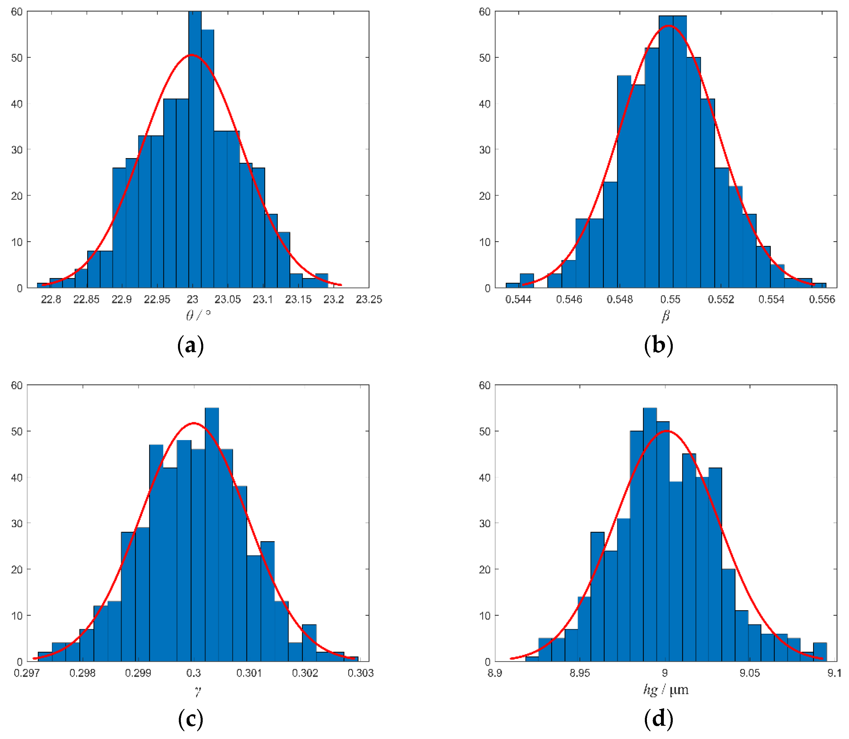
| Number | Parameter Name | Mean Value | Standard Deviation | Distribution Type |
|---|---|---|---|---|
| 1 | θ/° | 23 | 0.077 | Normal distribution |
| 2 | β | 0.55 | 0.00183 | Normal distribution |
| 3 | γ | 0.3 | 0.001 | Normal distribution |
| 4 | hg/μm | 9 | 0.03 | Normal distribution |
Disclaimer/Publisher’s Note: The statements, opinions and data contained in all publications are solely those of the individual author(s) and contributor(s) and not of MDPI and/or the editor(s). MDPI and/or the editor(s) disclaim responsibility for any injury to people or property resulting from any ideas, methods, instructions or products referred to in the content. |
© 2024 by the authors. Licensee MDPI, Basel, Switzerland. This article is an open access article distributed under the terms and conditions of the Creative Commons Attribution (CC BY) license (https://creativecommons.org/licenses/by/4.0/).
Share and Cite
Bei, G.; Xu, X.; Ma, C.; Sun, J.; Zhang, Y.; Yu, Q. Reliability Evaluation of a Dynamic-Pressure Mechanical Seal Based on Liquid Film Vaporization Phase Transition. Coatings 2024, 14, 233. https://doi.org/10.3390/coatings14020233
Bei G, Xu X, Ma C, Sun J, Zhang Y, Yu Q. Reliability Evaluation of a Dynamic-Pressure Mechanical Seal Based on Liquid Film Vaporization Phase Transition. Coatings. 2024; 14(2):233. https://doi.org/10.3390/coatings14020233
Chicago/Turabian StyleBei, Guangyao, Xiaodong Xu, Chenbo Ma, Jianjun Sun, Yuyan Zhang, and Qiuping Yu. 2024. "Reliability Evaluation of a Dynamic-Pressure Mechanical Seal Based on Liquid Film Vaporization Phase Transition" Coatings 14, no. 2: 233. https://doi.org/10.3390/coatings14020233