Article

Finite Element Simulation of Orthogonal Cutting of H13-Hardened Steel to Evaluate the Influence of Coatings on Cutting Temperature

School of Mechanical and Electrical Engineering, Shandong Jianzhu University, Jinan 250101, China
*
Author to whom correspondence should be addressed.
Coatings 2024, 14(3), 293; https://doi.org/10.3390/coatings14030293
Submission received: 29 December 2023 / Revised: 20 February 2024 / Accepted: 25 February 2024 / Published: 28 February 2024
(This article belongs to the Special Issue Technologies of Coatings and Surface Hardening for Tool Industry III)

Abstract

:
High cutting temperatures increase tool wear and reduce tool life. To achieve a longer tool life, coated carbide tools have been developed. In this study, the influence of tool coatings on the cutting temperature distribution during the orthogonal cutting of H13-hardened steel is investigated. Firstly, four coating materials, including TiC, TiN, Al2O3, and TiAlN, with the same coating thickness, are selected to evaluate the effects of coating materials on cutting temperature with finite element simulation. The maximum temperatures at the tool rake face and the temperatures at the coating–substrate interface are evaluated. It was found that the maximum temperatures at the tool rake face were the lowest and the highest when TiN and Al2O3 coating materials were applied, respectively. The TiAlN coating material had the best thermal barrier property. Then, the temperature distribution along the direction perpendicular to the tool rake face is investigated for TiAlN-coated tools with different coating thicknesses ranging from 3 μm to 10 μm. It is shown that the temperature gradient increases with the coating thickness. The coating thickness should be kept below 5 μm. Finally, cutting experiments validate the availability of the finite element model.

1. Introduction

Increased environmental awareness has led to a recent increase in the use of dry or minimal lubrication machining. Environmental problems can be avoided by a machining process without the use of cutting fluids. However, the cutting temperature is elevated in dry machining conditions. The increase in the maximum temperature at the rake face of the cutting tool causes a reduction in tool life. The high cutting temperature and temperature distribution of the tool can change the metallurgical structures of the tool’s materials [1]. Elevated cutting temperatures also result in the poor surface finish of machined parts. To achieve longer tool life and better quality of machined parts, various engineered cutting tool materials with extremely hot hardness, improved fracture toughness, and high resistance to abrasion and thermal shock are required. Coated cutting tools have been developed and are widely used in the manufacturing industry.
As shown in Figure 1, the heat transferred into coated cutting tools comes from three heat sources, including heat from the primary deformation zone, heat generated in the secondary deformation zone, and heat produced in the tertiary deformation zone. Although the areas of the heat generation zones are very small, the temperature can rise up to a high level of 800–1200 °C due to the high pressure [2]. The temperature distribution of a coated cutting tool is mainly affected by two main heat sources. One heat source is the shear plane at the primary shear zone. The other is the frictional heat source at the tool–chip interface [3]. The quantification of these two sources remains unclear in both cases of uncoated and coated cutting tools. Moreover, the influence of coatings on the amount of heat generated by these heat sources is complex. It is not fully understood whether the coatings influence the cutting process through an insulating effect (lower thermal conductivity) or through a tribological effect (the lower level of heat generated in the sources).
The most commonly used tool coating materials are TiN, TiC, TiCN, Al2O3, and TiAlN [4]. Some of the outstanding properties of tool coating materials are as follows. TiC coatings aid in reducing cratering. TiCN coatings help reduce crater formation. Al2O3 coating can act as a thermal barrier layer to protect the substrate from high cutting temperatures due to its low thermal conductivity. TiN helps to reduce interfacial friction and acts as a diffusion barrier [5]. TiAlN coatings have been developed as hard coatings with excellent properties for better oxidation resistance, higher hardness, and improved thermal stability compared to TiN [6].
TiN coatings have some attractive properties, such as high hardness, good wear resistance, and chemical stability [7,8]. In recent decades, TiN coatings have become increasingly important for improving the life and performance of cutting tools and many mechanical parts. The performances of TiN-coated tools and uncoated tools were compared and investigated by Akbar F. et al. [9]. It was verified that the TiN coating improves tribological performance by reducing the tool–chip contact area. In terms of heat distribution, TiN-coated tools reduce the heat distribution in coated tools. The heat partition of the TiN coating into tools decreased from 0.35 down to 0.095 for a whole range of cutting speeds (100 m/min–880 m/min). It was shown that the TiN coating could protect coated tools from high cutting temperatures. However, TiN coatings start to oxidize into TiO2 when the temperature is higher than 500 °C. The oxide layer leads to crack formation and brittle oxide layer delamination. This property can deteriorate the mechanical and tribological properties of coated tools at high cutting temperatures [10,11]. Recently, TiAlN coatings have been developed as hard coatings with excellent high-temperature properties [6,12]. In order to find out the differences in mechanical characteristics and thermal properties between TiN and TiAlN coatings, research has been carried out. Turning experiments were conducted on AISI/SAE 4140 high-strength alloy steel using TiN- and TiAlN-coated cutting tools [13]. The cutting speeds were increased from 100 m/min to 880 m/min. The tool chip contact areas for TiN-coated tools were larger than those for TiAlN-coated tools over the entire cutting speed range. The heat partitions in coated tools were evaluated using the finite element method. The results indicated that the use of single-layer TiN-coated tools could cause a reduction in heat partition in the coated cutting tool at a conventional cutting speed. However, in the high-speed machining (HSM) region, the reduction in heat partition became more dominant for the use of TiAlN-coated tools. It was concluded that TiAlN coatings could better improve the tribological performance. TiAlN coatings provide a lower thermal conductivity for tool systems and ultimately reduce the heat partition into the cutting tools. Chen L. et al. [14] explained the different properties of the two coatings by comparative research on grain size, hardness, and the bonding structure of TiN and TiAlN coatings. The results indicate that the addition of Al significantly decreased the grain size from 24.7 nm for TiN to 18.6 nm for the TiAlN coating. The hardness increased from 24 GPa for TiN to 31.2 GPa for TiAlN coating. Furthermore, continuous cutting and milling experiments were conducted to evaluate the performance of the coated inserts. It was found that TiAlN-coated tools had a longer tool life than TiN-coated tools in the continuous turning of stainless steel and in the milling of 42CrMo steel.
Orthogonal cutting experiments of medium carbon and austenitic stainless steels with single-layer (TiC), double-layer (TiC-TiN), and triple-layer (TiC-Al2O3-TiN)-coated WC-Co tools were investigated by Grzesik, W. [15]. It was observed that the use of appropriate tool coatings could decrease the coefficient of friction at the tool rake face. Klocke et al. [16] studied the effects of various coatings on contact conditions and wear mechanisms during the machining of ferrous and non-ferrous metals. The Al2O3 layer generated during the cutting process was also considered. They reported that TiAl-based and Al2O3-containing coatings changed the tool–chip contact conditions and significantly reduced them. Friction and adhesion between the tool and chip interface could be reduced, resulting in a lower cutting temperature at the tool rake face. Grzesik, W. [17] pointed out that the Al2O3 coating could act as a thermal barrier and protect the tool substrate from increased cutting temperature when machining medium carbon steel and austenitic stainless steel. Du, F. [18] found a very distinct influence of the Al2O3 coating on the thermal barrier and explained this due to its lower thermal conductivity compared to TiC and TiN coatings. To investigate the influence of coatings on heat transfer in coated inserts during machining, Kusiak A. et al. [19] analyzed turning steel experiments with five different coated cutting tools. The temperatures in the tools were measured by sensors embedded at a certain distance from the zone of the thermal load application. The characteristics of the coatings used are shown in Table 1. It was found that the Al2O3 coating resulted in the smallest heat flux in the tool, while the TiN, TiAlN, and TiAlN + MoS2 coatings did not have a significant influence with respect to the uncoated tool.
Coating thickness is one of the most important attributes of coating system performance. The effects of coating thickness on tool tribological performance have been widely researched. In general, thicker coatings exhibit better wear resistance performance than thinner coatings. However, some reports claim that different conclusions were obtained [20,21,22] using cutting experiments with diamond-coated tools. The authors demonstrated that the increased coating thickness was generally beneficial to tool life. However, thicker coatings caused a decrease in transverse rupture strength, which greatly affected the performance in high-speed or interrupted machining. Meanwhile, it was observed that a thicker coating resulted in higher cutting forces due to the increased cutting-edge radius. High cutting forces induced high cutting temperatures. However, for coated cutting tool applications, coating thickness may play a more complicated role. Qin, F. et al. [23] analyzed the influence of coating thickness on the machining process using the finite element software ANSYS. It was indicated that thicker coatings presented greater delamination resistance, whereas the critical load for coating failure decreased with the increasing coating thickness. According to Qin F. et al. [24], thicker multilayer coatings exhibited better scratch resistance than thinner coatings did due to their better load-carrying capacity.
The wear resistance of a coating depends not only on the properties of the coating material but also on its thickness. Bouzakis K.D. et al. [25] investigated the influence of coating thickness on the cutting performance of milling with TiAlN-coated tools. The coating thickness varied from 3 μm to 10μm. These investigations revealed that as the coating grew thicker, its superficial hardness and strength decreased. However, the thick coating did not affect the cutting performance as much as the thin coatings. To understand the effects of TiN’s coating thickness on the machining performance of TiN-coated cutting tools, Sargade, V.G. et al. [26] conducted a dry turning experiment with TiN-coated tools. The thicknesses of the TiN coatings ranged from 1.8 μm to 6.7 μm. It was found that the 4 μm TiN coating exhibited better coating retention on both the rake and flank surfaces during the dry machining of C40 steel compared to other coated inserts. Tuffy K. et al. [27] reported that there was an optimum coating thickness of TiN by PVD technology for certain machining conditions. Based on the test results for a range of 1.75 to 7.5 μm TiN coatings, a thickness of 3.5 μm showed the best turning performance.
Several researchers have focused on the mechanical and thermal properties of TiC, TiN, Al2O3, and TiAlN coatings. There are few papers paying attention to the influence of single-layer coating materials and coating thickness on the cutting temperature distribution in orthogonal cutting H13-hardened steel. In this work, TiC, TiN, Al2O3, and TiAlN, as four kinds of coating material, are investigated by the finite element method when machining H13-hardened steels. The maximum temperatures at the rake face and the temperatures at the coating–substrate interface are simulated. The temperature distribution along the direction perpendicular to the tool rake face is investigated for TiAlN-coated tools with different coating thicknesses ranging from 3 μm to 10 μm. Finally, orthogonal cutting experiments with TiN- and TiAlN-coated tools are performed to validate the availability of the finite element model.

2. Materials and Methods

The finite element method has been widely used to analyze the metal-cutting process. In this study, commercial finite element analysis software AdvantEdge (Third Wave Systems AdvantEdge v7.1) was applied to simulate the orthogonal cutting process, as illustrated in Figure 2b. In this study, the coated tools had the same geometric parameters. The cutting-edge radius was set to 0.01 mm. The cutting rake angle and tool clearance angle were kept constant at 0° and 3°, respectively. The cutting speed was 300 m/min. The undeformed chip thickness and cutting width were 0.1 mm and 2 mm, respectively. Then, orthogonal turning experiments were carried out to verify the availability of the finite element model.
The FE model used to simulate the orthogonal metal cutting process simulation was based on Lagrangian techniques, explicit dynamic, and thermo-mechanically coupled modeling technologies with adaptive re-meshing. The initial mesh became distorted after a certain cutting length and was re-meshed in this vicinity to form regular mesh again. The dimensions of the element size for the tool body and the workpiece covered a wide range, from the minimum value of 0.02 mm to the maximum value of 0.1 mm. The element size dimension for the coatings was set to 2 μm. Triangular elements were used to model the coated cutting tool and workpiece. The number of nodes for the simulation model in this study was 24,000. The physical and thermal properties of H13-hardened steel, the tool coating materials, and the tool substrate material are listed in Table 2.
The coated tools were modeled as rigid bodies because the tool materials had a high modulus of elasticity. The workpiece material was treated as elastic–plastic bodies. The initial and boundary conditions applied to the model for the cutting temperature analysis were as follows. The initial temperature of the tool and workpiece was set to room temperature (T0 = 20 °C). For the non-contact surfaces of the coated tools and workpiece, heat losses due to thermal convection were calculated using a convective coefficient of 20 W/(m2K). The FE simulation procedure is shown in Figure 3. The coating materials and their thicknesses were set after the geometric dimensions of the workpiece and coated tools were determined. The simulation results were analyzed using the Tecplot post-processor provided by AdvantEdge. Temperatures at selected points were extracted and evaluated.
To validate the finite element model, a computerized numerically controlled lathe was used to carry out the machining experiments, as shown in Figure 4. The maximum temperature of the rake face of coated tools was evaluated. TiAlN- and TiN-coated cutting tools were selected for cutting tests. With the tool holder used, the coated cutting inserts formed a 0° rake angle and a 3° clearance angle. The workpieces were thin circular plates made of H13-hardened steel. The orthogonal turning tests were performed at a cutting speed of 300 m/min. The uncut chip thickness and cutting width were 0.1 mm and 2 mm, respectively. No coolant was applied during the cutting process. To verify the prediction of the finite element model, the results of the cutting experiments and the finite element simulations were compared.
Many techniques have been applied to measure the temperature during the metal-cutting process. Each technique has its own advantages and limitations depending on the applied measurement conditions [30,31,32,33,34]. In this experiment, cutting temperatures of the contact zone between coated tools and chips were obtained using the IR camera FLIR A315. The IR camera has a long wave and self-cooling analysis system. The infrared radiation camera used in this experiment has a thermal sensitivity of 50 mK at 30 °C. The quantum well-infrared photon detector has a spectral range of 7.5 to 13 μm with a resolution of 320 × 240 mm pixels. The spatial resolution of the IR camera was 1.36 mrad. The image frame frequency of the camera was 60 Hz. The measurement error of the IR camera was ±2 °C. The range of measure temperatures of FLIR A315 was −20 °C to 1200 °C. The lens applied in the study could automatically identify the observed target. The captured images were transferred to a special computer with built-in ThermaCAM analysis software FLIR Tools (using the FLIR system).

3. Results and Discussion

The simulated cutting temperature results of the four coated tools are discussed. The maximum temperature of the coated tools appeared at a location about 0.1 mm distance from the tool tip along the rake face, as shown in Figure 5. The cutting temperature at the tool–chip interface first increased and then decreased with increasing the increasing distance from the tool tip. The heat conduction along the direction perpendicular to the coated tool rake face was investigated. It was found that the four coating materials could protect the tool substrate materials from elevated temperatures due to their low thermal conductivity, as shown in Table 2.
Temperatures at two points were analyzed for coated tools. One was the point where the maximum temperature was at the tool rake face. Another one was along the direction perpendicular to the coated tool rake face from the first point and at the interface between the tool coating and the tool substrate. The positions of these two points are shown in Figure 5. The temperatures at the two points are presented in Figure 6. The Al2O3-coated tool generated the highest maximum temperature at the rake face compared to the other three coated tools. The temperature was up to 1171 °C. On the contrary, the lowest maximum temperature was presented on a TiN-coated tool rake face. The maximum temperature at the rake face of the TiN-coated tool was 1129 °C. TiN-coated material has a lower coefficient of friction than the other three materials [9]. The heat generated at the contact interface between the tool rake face and chip was less. Previous studies have shown that the titanium element could reduce the friction coefficient between the coated tool rake face and chip [9,15].
The temperature gradient between the tool rake face and the coating–substrate interface explains the thermal barrier properties of the coating materials. It was found that all of the four coating materials could act as thermal barrier layers. However, Al2O3- and TiAlN-coated materials generated a greater decrease in temperature from the rake face to the interface between the tool coating and tool substrate than TiN and TiC. For the TiAlN-coated tool, the temperature at the interface between the coating and substrate was 126 °C lower than that of the rake face. For the Al2O3-coated tool, the temperature gradient was 122 °C. The temperature gradients were 116 °C and 108 °C for TiC and TiN coatings, respectively. TiAlN and Al2O3 coatings exhibited better thermal barrier properties than the other two coating materials, which could be attributed to their lower thermal conductivity. The thermal conductivities of TiAlN- and Al2O3-coated materials were 12.61 W/(m·K) and 14 W/(m·K), respectively. Correspondingly, the thermal conductivities of TiN and TiC were 21 W/(m·K) and 24 W/(m·K), respectively.
The temperature distributions for TiAlN-coated tools with different coating thicknesses are shown in Figure 7a–d. The maximum temperatures at the rake face of the coated tools were investigated. Eleven points along the direction perpendicular to the rake face from the point showing the maximum temperature were also investigated. The temperatures at these twelve points were extracted and analyzed using AdvantEdge software. The temperature distributions of coated tools were affected by coating thickness in two ways. As the coating thickness increased, the thermophysical properties of the coating materials changed [9]. Then, the heat transferred into coated tools was changed. In another way, thicker coating layers meant that a longer distance of heat transfer was required. Therefore, various coating thicknesses lead to different temperature distributions in coated tools.
The temperatures at selected points are presented in Figure 8. It can be seen that the maximum temperature at the tool rake face and the temperature of the tool substrate decreased as the coating thickness increased. The temperature dropped rapidly from the tool rake face to the coating–substrate interface. The temperature gradient between the temperature on the rake face and that on the coating–substrate interface increased with the increase in the coating thickness. When the tool coating thickness reached 7 μm and 10 μm, the temperature decrease was almost 300 °C. For coating thicknesses of 3 μm and 5 μm, the temperature decreases were 119 °C and 184 °C, respectively. The temperature gradient was so great that a large thermal stress could be generated near the coating–substrate interface. The thermal stress (σth) of the coating film can be calculated by Equation (1)
σ t h = E F ( α f i l m α s u b s t r a t e ) Δ T
where EF (GPa) is the elastic modulus of the coating film. αfilm and αsubstrate (m2/s) are the coefficients of thermal expansion of the coating and substrate, respectively. ΔT (°C) is the temperature reduction from the coated tools’ rake face to the coating–substrate interface.
For the same coating–substrate system, the thermal stress increases with ΔT. It is generally believed that greater thermal stress could lead to coating failure. A smaller temperature reduction alleviates the generation of thermal stress. To achieve longer tool life, the thickness of the coating layer should be kept less than 5 μm.
To validate the finite element model, machining experiments were carried out. The cutting temperatures of the contact zone between coated tools and chips were obtained using the IR camera FLIR A315. The temperature of an object measured by an IR camera depends strongly on the emissivity of the material. The average emissivity coefficients of TiN- and TiAlN-coated inserts were determined to be 0.21 and 0.45, respectively [13]. The distance between the IR camera and the detected area was 1.5 m. The background temperature was 20 °C. The relative humidity was 42%.
It can be seen in Figure 9 that the maximum temperatures of the tool rake face are 1063.65 °C and 1047.44 °C when coating materials were TiAlN and TiN, respectively. Comparing the maximum cutting temperature of the rake face obtained using cutting tests and FE simulation, the error percentages were 7.34% and 7.26% for TiAlN- and TiN-coated cutting tools, respectively. The results of the finite element model are in good agreement with those of the cutting experiments.

4. Conclusions

In this paper, the temperature distribution and heat conduction of different coated cutting tools were investigated with FEM AdvantEdge software. The maximum temperature at the tool rake face alongside the coating–substrate interface temperature were evaluated for four coated tool materials. The temperature distributions of TiAlN-coated tools with various coating thicknesses were investigated. The following conclusions can be drawn from the simulated and experimentally measured cutting temperatures.
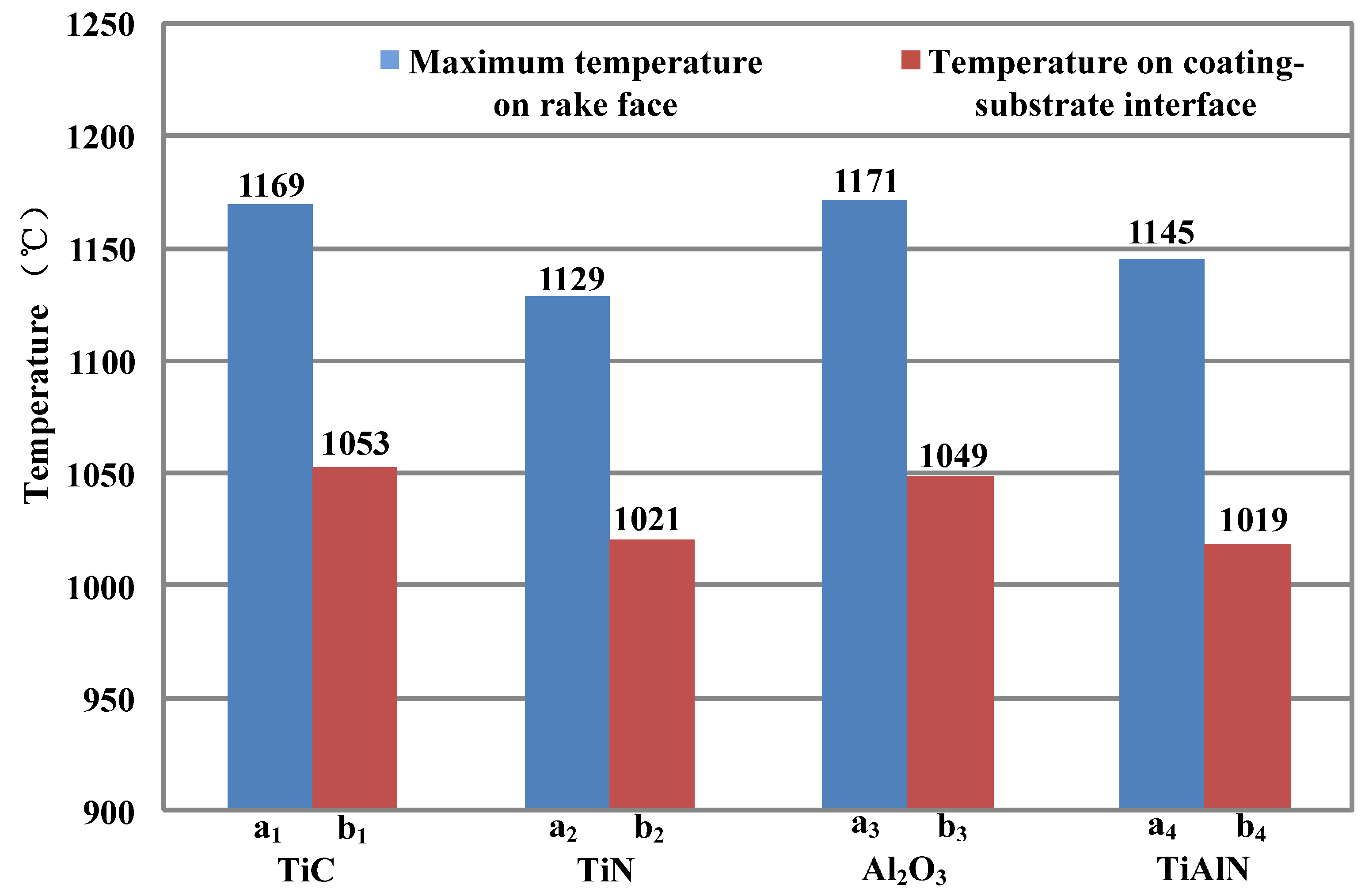
  • The four coating materials play a thermal barrier role. TiAlN coating material was superior to the other three coating materials for the thermal barrier. The temperature gradient was about 128 °C between the rake face and coating–substrate interface. The better thermal barrier property of the TiAlN coating was due to its lower thermal conductivity. In order to ensure that the coated tool substrate had a lower temperature to maintain better-cutting performance, the TiAlN coating was recommended as the preferred coating.
  • The thicker the TiAlN coating, the greater the temperature gradient between the tool rake face and coating–substrate interface. The temperature gradient reached about 300 °C when the coating thicknesses were 7 μm and 10 μm. A greater temperature gradient generally led to coating failure. The tool coating thickness had best be kept less than 5 μm from the view of thermal stress generated by the cutting temperature.
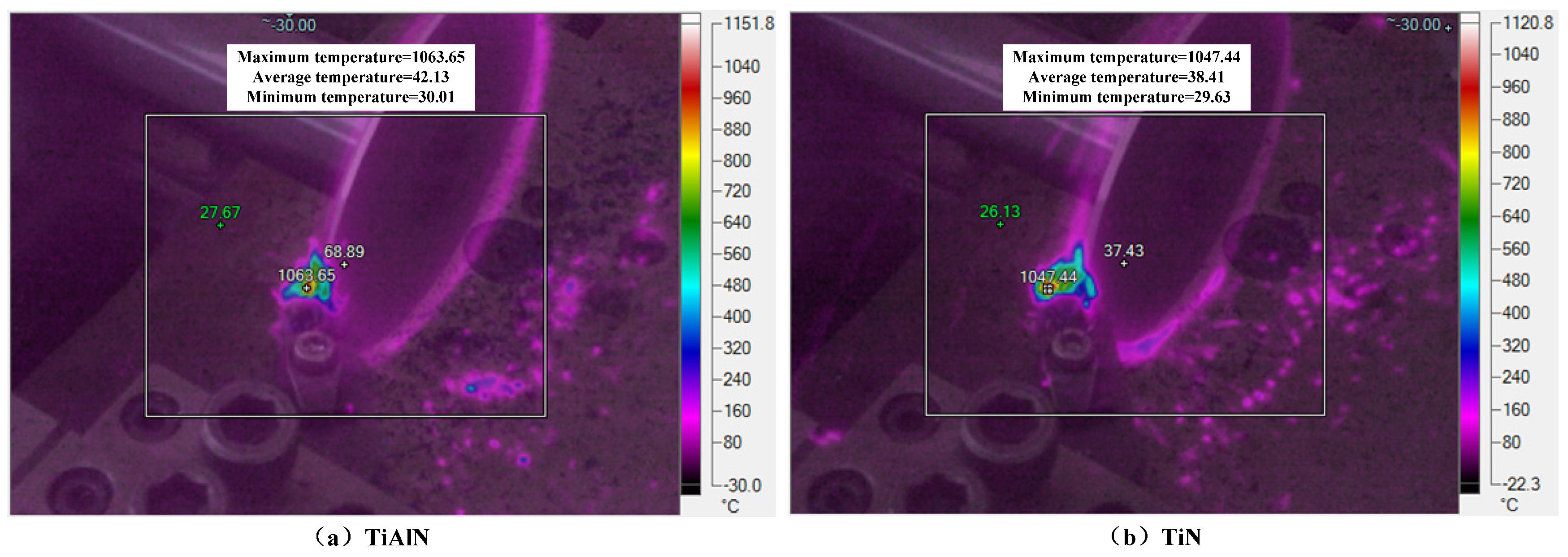
  • The maximum temperature of the rake face of TiAlN- and TiN-coated tools was evaluated in dry orthogonal turning tests. Comparing the maximum cutting temperature of the rake face obtained by cutting tests and FE simulation, the error percentages were 7.34% and 7.26% for TiAlN- and TiN-coated cutting tools, respectively. The results of the finite element model are in good agreement with those of the cutting experiments.

Author Contributions

Conceptualization, G.H.; methodology, G.H. and A.T.; software, G.H.; validation, G.H. and Z.Z.; formal analysis, G.H.; investigation, G.H.; resources, G.H. and H.X.; data curation, G.H. and R.D.; writing—original draft preparation, G.H.; writing—review and editing, G.H. and A.T.; visualization, G.H. and N.X.; supervision, G.H., A.T. and N.X.; project administration, G.H.; funding acquisition, G.H. All authors have read and agreed to the published version of the manuscript.

Funding

This research was funded by [the Shandong Provence Natural Science Foundation] grant number [No. ZR2022QE156] This work was also supported by grants from [the Shandong Provence Natural Science Foundations] grant numbers [No. ZR2021QE244 and ZR2021QE286].

Institutional Review Board Statement

Not applicable.

Informed Consent Statement

Not applicable.

Data Availability Statement

Data are contained within the article.

Conflicts of Interest

The authors declare no conflict of interest.

References

  1. Zhao, J.; Liu, Z.; Wang, B.; Hu, J.; Wan, Y. Tool coating effects on cutting temperature during metal cutting processes: Comprehensive review and future research directions. Mech. Syst. Signal Process. 2021, 150, 107302. [Google Scholar] [CrossRef]
  2. Wang, Y.; Wang, Z.; Ni, P.; Wang, D.; Lu, Y.; Lu, H.; Guo, S.; Chen, Z. Experimental and numerical study on regulation of cutting temperature during the circular sawing of 45 steel. Coatings 2023, 13, 758. [Google Scholar] [CrossRef]
  3. Liu, C.; Liu, B.; Zhou, Y.; He, Y.; Chi, D.; Gao, X.; Liu, Q. A real-time cutting temperature monitoring of tool in peripheral milling based on wireless transmission. Int. J. Therm. Sci. 2023, 186, 108084. [Google Scholar] [CrossRef]
  4. Ucun, İ.; Aslantas, K. Numerical simulation of orthogonal machining process using multilayer and single-layer coated tools. Int. J. Adv. Manuf. Technol. 2011, 54, 899–910. [Google Scholar] [CrossRef]
  5. Özel, T.; Altan, T. Determination of workpiece flow stress and friction at the chip–tool contact for high-speed cutting. Int. J. Mach. Tools Manuf. 2000, 40, 133–152. [Google Scholar] [CrossRef]
  6. Grzesik, W. Friction behaviour of heat isolating coatings in machining: Mechanical, thermal and energy-based considerations. Int. J. Mach. Tools Manuf. 2003, 43, 145–150. [Google Scholar] [CrossRef]
  7. Sousa, V.F.C.; Fernandes, F.; Silva, F.J.G.; Costa, R.D.F.S.; Sebbe, N.; Sales-Contini, R.C.M. Wear Behavior Phenomena of TiN/TiAlN HiPIMS PVD-Coated Tools on Milling Inconel 718. Metals 2023, 13, 684. [Google Scholar] [CrossRef]
  8. Chang, K.; Dong, Y.; Zheng, G.; Jiang, X.; Yang, X.; Cheng, X.; Liu, H.; Zhao, G. Friction and wear properties of TiAlN coated tools with different levels of surface integrity. Ceram. Int. 2022, 48, 4433–4443. [Google Scholar] [CrossRef]
  9. Akbar, F.; Mativenga, P.T.; Sheikh, M.A. An evaluation of heat partition in the high-speed turning of AISI/SAE 4140 steel with uncoated and TiN-coated tools. Proc. Inst. Mech. Eng. Part B J. Eng. Manuf. 2008, 222, 759–771. [Google Scholar] [CrossRef]
  10. Kıvak, T.; Sarıkaya, M.; Yıldırım, Ç.V.; Şirin, Ş. Study on turning performance of PVD TiN coated Al2O3+TiCN ceramic tool under cutting fluid reinforced by nano-sized solid particles. J. Manuf. Process. 2020, 56, 522–539. [Google Scholar] [CrossRef]
  11. Héau, C.; Fillit, R.; Vaux, F.; Pascaretti, F. Study of thermal stability of some hard nitride coatings deposited by reactive magnetron sputtering. Surf. Coat. Technol. 1999, 120, 200–205. [Google Scholar] [CrossRef]
  12. Mallick, R.; Kumar, R.; Panda, A.; Sahoo, A.K. Current status of hard turning in manufacturing: Aspects of cooling strategy and sustainability. Lubricants 2023, 11, 108. [Google Scholar] [CrossRef]
  13. Akbar, F.; Mativenga, P.T.; Sheikh, M.A. On the heat partition properties of (Ti, Al) N compared with TiN coating in high-speed machining. Proc. Inst. Mech. Eng. Part B J. Eng. Manuf. 2009, 223, 363–375. [Google Scholar] [CrossRef]
  14. Chen, L.; Wang, S.Q.; Du, Y.; Li, J. Microstructure and mechanical properties of gradient Ti (C, N) and TiN/Ti (C, N) multilayer PVD coatings. Mater. Sci. Eng. A 2008, 478, 336–339. [Google Scholar] [CrossRef]
  15. Grzesik, W. An integrated approach to evaluating the tribo-contact for coated cutting inserts. Wear 2000, 240, 9–18. [Google Scholar] [CrossRef]
  16. Klocke, F.; Krieg, T.; Gerschwiler, K.; Fritsch, R.; Zinkann, V.; Pöhls, M.; Eisenblätter, G. Improved cutting processes with adapted coating systems. CIRP Ann. 1998, 47, 65–68. [Google Scholar] [CrossRef]
  17. Grzesik, W. Experimental investigation of the cutting temperature when turning with coated indexable inserts. Int. J. Mach. Tools Manuf. 1999, 39, 355–369. [Google Scholar] [CrossRef]
  18. Du, F.; Lovell, M.R.; Wu, T.W. Boundary element method analysis of temperature fields in coated cutting tools. Int. J. Solids Struct. 2001, 38, 4557–4570. [Google Scholar] [CrossRef]
  19. Kusiak, A.; Battaglia, J.L.; Rech, J. Tool coatings influence on the heat transfer in the tool during machining. Surf. Coat. Technol. 2005, 195, 29–40. [Google Scholar] [CrossRef]
  20. Wang, D.F.; Kato, K. Effect of coating thickness on friction for carbon nitride films in repeated sliding against a spherical diamond with nano-scale asperities. Wear 2002, 252, 210–219. [Google Scholar] [CrossRef]
  21. Deuerler, F.; Lemmer, O.; Frank, M.; Pohl, M.; Heßing, C. Diamond films for wear protection of hardmetal tools. Int. J. Refract. Met. Hard Mater. 2002, 20, 115–120. [Google Scholar] [CrossRef]
  22. Kanda, K.; Takehana, S.; Yoshida, S.; Watanabe, R.; Takano, S.; Ando, H.; Shimakura, F. Application of diamond-coated cutting tools. Surf. Coat. Technol. 1995, 73, 115–120. [Google Scholar] [CrossRef]
  23. Qin, F.; Chou, Y.; Nolen, D.; Thompson, R. Coating thickness effects on diamond coated cutting tools. Surf. Coat. Technol. 2009, 204, 1056–1060. [Google Scholar] [CrossRef]
  24. Qin, F.; Chou, Y.K.; Nolen, D.; Thompson, R.G. Diamond Coatings for Machining: Coating Thickness Effects. In Proceedings of the International Manufacturing Science and Engineering Conference, West Lafayette, IN, USA, 4–7 October 2009; Volume 43611, pp. 485–491. [Google Scholar]
  25. Bouzakis, K.-D.; Hadjiyiannis, S.; Skordaris, G.; Mirisidis, I.; Michailidis, N.; Efstathiou, K.; Pavlidou, E.; Erkens, G.; Cremer, R.; Rambadt, S.; et al. The effect of coating thickness, mechanical strength and hardness properties on the milling performance of PVD coated cemented carbides inserts. Surf. Coat. Technol. 2004, 177, 657–664. [Google Scholar] [CrossRef]
  26. Sargade, V.G.; Gangopadhyay, S.; Paul, S.; Chattopadhyay, A.K. Effect of coating thickness on the characteristics and dry machining performance of TiN film deposited on cemented carbide inserts using CFUBMS. Mater. Manuf. Process. 2011, 26, 1028–1033. [Google Scholar] [CrossRef]
  27. Tuffy, K.; Byrne, G.; Dowling, D. Determination of the optimum TiN coating thickness on WC inserts for machining carbon steels. J. Mater. Process. Technol. 2004, 155, 1861–1866. [Google Scholar] [CrossRef]
  28. Ng, E.-G.; Aspinwall, D.; Brazil, D.; Monaghan, J. Modelling of temperature and forces when orthogonally machining hardened steel. Int. J. Mach. Tools Manuf. 1999, 39, 885–903. [Google Scholar] [CrossRef]
  29. Kadhim, K.J.; Rahman, N.A.; Salleh, M.R.; Zukee, K.I.M. Effects of Layer Thickness on the Microstructures of TiN/AlTiN Multilayer Coatings. Appl. Mech. Mater. 2015, 761, 417–420. [Google Scholar] [CrossRef]
  30. Davies, M.; Ueda, T.; M’Saoubi, R.; Mullany, B.; Cooke, A. On the measurement of temperature in material removal processes. CIRP Ann. 2007, 56, 581–604. [Google Scholar] [CrossRef]
  31. Weng, J.; Saelzer, J.; Berger, S.; Zhuang, K.; Bagherzadeh, A.; Budak, E.; Biermann, D. Analytical and experimental investigations of rake face temperature considering temperature-dependent thermal properties. J. Mater. Process. Technol. 2023, 314, 117905. [Google Scholar] [CrossRef]
  32. Pereira Guimaraes, B.M.; da Silva Fernandes, C.M.; Amaral de Figueiredo, D.; da Silva, F.S.C.P.; Miranda, M.G.M. Cutting temperature measurement and prediction in machining processes: Comprehensive review and future perspectives. Int. J. Adv. Manuf. Technol. 2022, 120, 2849–2878. [Google Scholar] [CrossRef]
  33. Serio, L.; Palumbo, D.; Galietti, U.; De Filippis, L.; Ludovico, A. Monitoring of the friction stir welding process by means of thermography. Nondestruct. Test. Eval. 2016, 31, 371–383. [Google Scholar] [CrossRef]
  34. Serio, L.M.; Palumbo, D.; De Filippis, L.A.C.; Galietti, U.; Ludovico, A.D. Effect of friction stir process parameters on the mechanical and thermal behavior of 5754-H111 aluminum plates. Materials 2016, 9, 122. [Google Scholar] [CrossRef] [PubMed]
Figure 1. Heat generation zones during the machining process.
Coatings 14 00293 g001
Figure 2. (a) Schematic diagram of orthogonal cutting test; (b) cutting temperature distribution obtained by the finite element method.
Coatings 14 00293 g002
Figure 3. Flowchart of the FE simulation process.
Coatings 14 00293 g003
Figure 4. Experimental set-up employed during the orthogonal turning tests.
Coatings 14 00293 g004
Figure 5. Temperature distribution in coated tools with various coating materials: (a) TiC coated tools; (b) TiN coated tools; (c) Al2O3 coated tools; (d) TiAlN coated tools.
Coatings 14 00293 g005
Figure 6. Temperatures at rake face and coating–substrate interface for different coating materials.
Coatings 14 00293 g006
Figure 7. Temperature distributions of coated tools with different TiAlN coating thicknesses: (a) TiAlN coating with 3 μm thickness; (b) TiAlN coating with 5 μm thickness; (c) TiAlN coating with 7 μm thickness; (d) TiAlN coating with 10 μm thickness.
Coatings 14 00293 g007
Figure 8. Temperature variation with the distance perpendicular to the rake face.
Coatings 14 00293 g008
Figure 9. Temperature measured at the rake face measured by FLIR A315: (a) TiAlN coated tools; (b) TiN coated tools.
Coatings 14 00293 g009
Table 1. Characteristics of the coatings used in turning experiments [19].
CoatingDeposition TechniqueThickness (μm)
TiNPVD-Cathodic Arc2
TiAlN + WC/CPVD-Cathodic Arc + sputtering4
Al2O3CVD5
TiAlNPVD-Cathodic Arc2
TiAlN + MoS2PVD magnetron sputtering4
Table 2. Thermal or physical properties of H13-hardened steel and coated tools.
MaterialsDensity (kg/m3)Young’s Modulus (GPa)Poisson’s RatioSpecific Heat Capacity (J/(kg·K))Thermal Diffusivity (10−5 m2/s)Thermal Conductivity (W/(m·K))
H13 [28]78002110.285600.8537
Cemented carbide [9]11,9005340.22346.010.9840.15
TiC [29]37005870.21878.130.9824
TiN [9]54202500.25702.600.5521
Al2O3 [4]37804150.239030.4914
TiAlN [9]18923700.22639.891.0412.61
Disclaimer/Publisher’s Note: The statements, opinions and data contained in all publications are solely those of the individual author(s) and contributor(s) and not of MDPI and/or the editor(s). MDPI and/or the editor(s) disclaim responsibility for any injury to people or property resulting from any ideas, methods, instructions or products referred to in the content.

