Article

Effects of Laser Remelting on Frictional Properties of Supersonic Flame-Sprayed Coatings

1
School of Metallurgical Engineering, Xi’an University of Architecture and Technology, Xi’an 710055, China
2
ShanMei Group New Energy Hydrogen Energy Technology Co., Ltd., Xi’an 710100, China
*
Authors to whom correspondence should be addressed.
Coatings 2024, 14(3), 325; https://doi.org/10.3390/coatings14030325
Submission received: 19 February 2024 / Revised: 3 March 2024 / Accepted: 7 March 2024 / Published: 9 March 2024
(This article belongs to the Special Issue The Present Status of Thermally Sprayed Composite Coatings)

Abstract

:
In this study, Cr3C2-Al2O3-NiCr coatings were prepared on INCONEL 600 alloy surfaces using the supersonic flame spraying technique, followed by a laser remelting treatment. In this way, this study further explored what impacts laser remelting has on coating performance. To this end, optical microscopy (OM), scanning electron microscopy (SEM), and electron backscatter diffraction (EBSD) were employed to carry out microstructural characterization. Energy-dispersive X-ray spectroscopy (EDS) was applied to conduct an analysis of the coatings’ elemental distribution while X-ray diffraction (XRD) was used to determine the coating phases. To measure the microhardness of the coatings, a microhardness tester was applied. In addition, the study investigated the samples’ electrochemical corrosion resistance and friction-wear performance under different surface conditions. According to the results, laser remelting enhanced the coating density, improved metallurgical bonding with the substrate, and optimized the carbide distribution, thereby enhancing corrosion and wear resistance in both air and corrosive media. However, excessive laser power hinders Cr3C2 nucleation, leading to diminished coating hardness and wear resistance in Cr7C3 formation.

1. Introduction

The exceptional durability of nickel and nickel alloys makes them crucial in challenging operational environments. They are applied in diverse sectors, including corrosive media-exposed components in chemical equipment, high-temperature-resistant parts in aerospace engines, and high-speed mechanical components [1,2]. The wide application of nickel alloys can be explained by their desirable material properties and versatile alloy design, facilitated by their extensive solubility and unique metallic phases with various elements. To handle severe abrasive conditions, hard ceramic particles are often added to the coatings to enhance wear resistance [3,4,5].
Belonging to the solid solution strengthening type of nickel-base high-temperature alloy materials, INCONEL 600 alloy exhibits excellent high-temperature characteristics, which has led to its wide application in nickel-base high-temperature alloy materials. Rich in nickel, this alloy features a single austenite structure, which enables good resistance to stress corrosion caused by chloride ions. The substantial amount of chromium significantly promotes its resistance to sulfide stress corrosion cracking and high-temperature oxidation [6,7]. This alloy is extensively applied in steam generators and chemical containers and the former have particularly higher requirements for material performance. It is listed as a level one safety material in nuclear power units. Based on the operational practices in foreign nuclear power plants, the damage in steam generator heat transfer tubes accounts for more than 50% of the accidents [8,9]. With the development of modern technology, industries are imposing higher quality requirements for INCONEL 600 alloy. However, there are still limitations in improving the performance of nickel-based alloys by enhancing the material itself. Moreover, the transition from research to engineering applications requires a long period of verification. Therefore, surface modification methods have become a research hotspot in the improvement of the service performance of nickel-base high-temperature materials.
In pursuit of augmented wear resistance, surface engineering entails altering the substrate material and structure as well as fabricating wear-resistant coatings. Generally, those coatings are divided into two categories, namely diffusion and overlay. Take c-diffusion coatings [10] and N-diffusion coatings [11] for example; they are formed directly through physical or chemical deposition onto alloy surfaces. Unlike diffusion coatings, overlay coatings exclude the substrate from the formation process, entailing more diversified coating compositions. Various preparation methods, including laser cladding [12], surface overlay welding [13], and explosive spraying [14], have been introduced. Thermal spraying, a scalable and cost-effective technique, has found extensive application in engineering for Cr3C2-NiCr coating fabrication [15,16,17]. However, the inherent defects of thermal spray coatings like micro-pores, micro-cracks, and poor adhesion fail to be fully eliminated, leading to a reduction in their performance [18,19]. Hence, effective post-treatment methods for changing coating structure and properties are being sought.
Laser remelting, an advanced surface treatment, holds the potential to enhance diverse coating attributes [20,21,22]. Through intense laser energy focus and rapid heating, the coating surface experiences instantaneous melting and recrystallization, rejuvenating crystal structures and refining microstructures and consequently reducing defects and enhancing interfacial adhesion [23,24,25]. To achieve an improvement in the performance of flame-sprayed coatings, numerous studies have been conducted by researchers, which proved that laser re-melting process parameters did play a vital role in boosting the performance of the coating. According to the findings of Qian et al. [26], the bond strength witnessed a three-fold increase and the tribological properties went through a significant improvement due to the metallurgical bond between the re-melted coating and the metal matrix after a laser re-melting treatment. Zhao [27] delved into how different laser remelting trajectories impacted the microstructure defects and tribological properties of the coatings; these results revealed that the circular remelting trajectory can effectively suppress pore and crack formation and development. Zhang et al. [28] put forward the idea that during the laser remelting process, the appearance and even distribution of many hard phases like Cr7C3, Ni3B, Cr23C6, and CrB could lead to a significant enhancement in the tribological properties of the coatings. García et al. [29] explored HVOF WC blended coatings and laser remelting of the resulting coating; the results showed that the fatigue life was extended in the laser-treated coatings. Peng et al. [30] investigated how laser remelting power and scanning speed affected the corrosion resistance of coatings. Under the same energy density, a lower laser power and higher scanning speed can reduce the number of cracks, thereby further reducing the channels through which corrosive media can penetrate into the coating and thereby improving the coating’s performance in heat corrosion resistance. In terms of microstructure, the study found that the remelted WC-Co spray coating formed a dense arrangement of dendritic and block-like microstructures, with fine and uniform particles. Various carbides were dispersed in the overlay, contributing to the strengthening effect. These changes significantly boosted the coating’s hardness [31]. The residual stress created in laser-treated HVOF coatings was investigated by Yilbas and Arif [32], whose results suggested that a compressive residual stress was formed on the surface. Moreover, such stress became tensile and had an increased distance from the surface towards the coating interface.
The research on laser remelting of Cr3C2-Al2O3-NiCr metal–ceramic composite coatings remains limited. Preliminary research [33] has shown that post-treatment techniques, such as shot peening, are equipped with the ability to notably improve the performance of wear resistance of Cr3C2-Al2O3-NiC coatings, but shot peening has certain limitations. To explore the impacts on phase composition, microstructure, mechanical properties, corrosion resistance, and wear resistance of Cr3C2-Al2O3-NiCr coatings posted by laser remelting, this study employed supersonic spraying to fabricate Cr3C2-Al2O3-NiCr coatings, and then performed a laser remelting treatment. Furthermore, the underlying mechanisms were further discussed.

2. Materials and Methods

In this study, the INCONEL600 alloy was used as the substrate material, with Table 1 listing its chemical composition. The spraying powder consists of 25% Cr3Cr2 powder, 5% Al2O3 powder, and 70% NiCr powder, which were evenly mixed using the mechanical ball milling method. Before the spraying treatment, the surface of the INCONEL600 alloy underwent polishing, degreasing, and sandblasting.
A KY-HVO(A)F (Xi’an, China) type sprayer was employed as the spraying equipment, with aviation kerosene as the fuel, high-pressure oxygen as the combustion oxidizing gas, and nitrogen as the powder spraying gas. The spray distance is 350 mm, the powder feed rate is 50 g/min, and the oxygen flow rate is 15 L/s. An LiM-SC (Xi’an, China) laser cladding machine was used as the laser remelting equipment. During the spraying process, the fuel and high-pressure oxygen were mixed and burned in the nozzle, producing a high-temperature and high-speed flame flow. The resulting flame was then accelerated, mixed, and used to melt the spray powder, aiming to generate a coating by hitting the substrate surface at high speed. After spraying, a laser remelting process was conducted under atmospheric conditions, with a scanning speed of 500 mm/min, an overlap rate of 50%, and chosen laser powers of 800 W, 1200 W, and 1800 W.
The cross-sectional metallographic structure of the coating was observed with an OLYMPUS-GX51 microscope (OLYMPUS, Tokyo, Japan). Using a JSM-6460 (JEOL Ltd, Tokyo, Japan) scanning electron microscope (equipped with EDS and EBSD), the coating’s micro-morphology, wear marks, and elemental distribution were all observed. The microhardness of the samples was measured using an MH-5 (Shanghai Hengyi Technology Company, Shanghai, China) microhardness tester (with a load of 5 N, loading time of 15 s, descent speed of 50 μm/s, and averaging 5 data points per measurement). With the help of the CHI800D (Shanghai Chenhua Instrument Co., Ltd., Shanghai, China) electrochemical workstation whose scanning range was −1.0 to 1.0 V and 5% HCl solution as the corrosive medium, the Taffel curves of the samples were examined. By employing a SHIMADZU-XRD (SHIMADZU, Kyoto, Japan) equipped with Cu-Ka radiation and a diffraction angle range from 30 to 56 degrees, the phase composition of the coating prior to and after the laser remelting treatment was characterized. An industrial CT (Huiyan Technology Co., Ltd., Beijing, China) was employed to measure the porosity of the coating before and after the laser remelting treatment (tomography parameters were as follows: voxel size, 5 µm; voltage, 100 kV; current, 70 µA).
All surfaces of the samples employed in the friction wear tests were uniformly polished with #1500 sandpaper. The friction wear tests were conducted with the help of an MSR-2T (Lanzhou Zhongke Kaihua Technology Development Co., Ltd., Lanzhou, China) reciprocating friction wear testing machine for 30 min with a load of 200 g. The experimental procedure was to first apply a load of 200 g and then carry out the friction wear tests; the load remained constant throughout the entire friction testing process. The upper sample was an Al2O3 ball with a diameter of 6 mm, a Vickers hardness of approximately 2035 HV, and a density of 3.6 g/cm3. The lower sample worked as a test sample, with a load from the upper weights, testing speed of 40 mm/min, and a stroke of 5 mm, in the air or a 5% hydrochloric acid medium. This study conducted the friction wear tests at room temperature to record how the trend of the friction coefficient changed with time with the help of MSR-2T software (vb6.0). Using a DSX510 (Olympus, Tokyo, Japan) three-dimensional profiler, the cross-sectional profile of the material’s wear zone was measured. The calculation of the wear rate is represented as Formula (1):
W r = W v S × L
  • Wr—Rate of wear mm3/(N·m).
  • Wv—Wear volume (mm3).
  • S—Sliding distance (mm).
  • L—Load (N).

3. Results

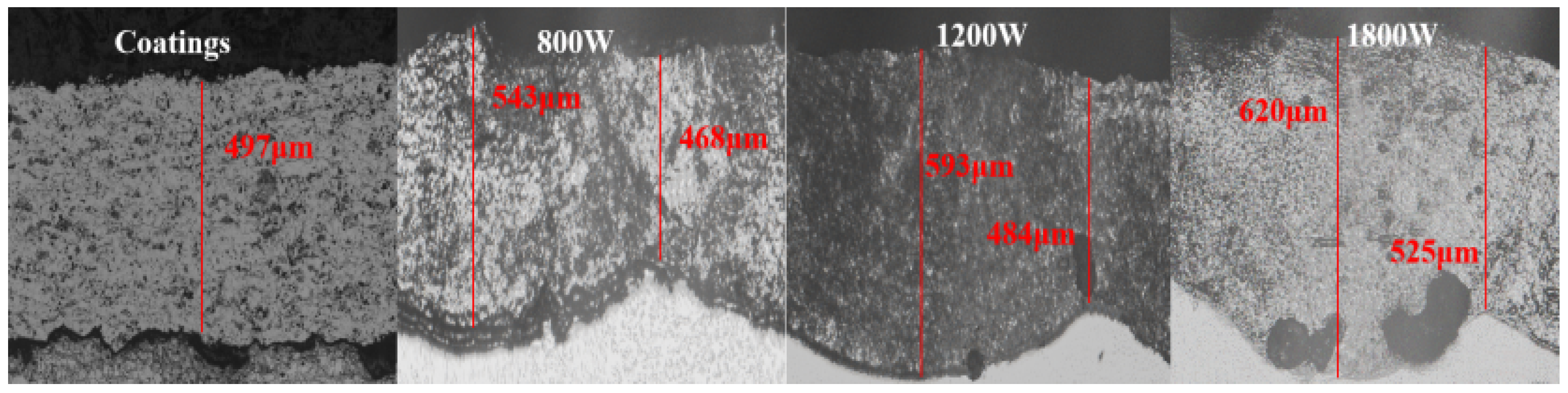
3.1. Metallographic Analysis

Figure 1 shows the cross-sectional metallographic images of the coatings prior to and after the laser remelting treatment, with the red lines indicating the depths of different areas of the coating.. The as-sprayed coating showed a loose structure with dispersed porosities. After a laser remelting at 800 W, the coating density notably increased while the porosities decreased. However, at 1200 W, larger voids appeared within the coating, and increasing the power to 1800 W led to even larger voids and a coarsened microstructure. Furthermore, the as-sprayed coating had a relatively uniform thickness, while the coating after laser remelting exhibited an uneven thickness in a wavy pattern. Moreover, as the laser power increased, the maximum depth of the coating also increased. Excessive energy input extends the molten pool’s residence time, thereby intensifying coating melting and prolonging recrystallization and leading to grain growth. Moreover, a higher melting degree boosts protective gas entrapment, contributing to the gas porosity during laser remelting [27,34], thus resulting in a negative impact on wear resistance.

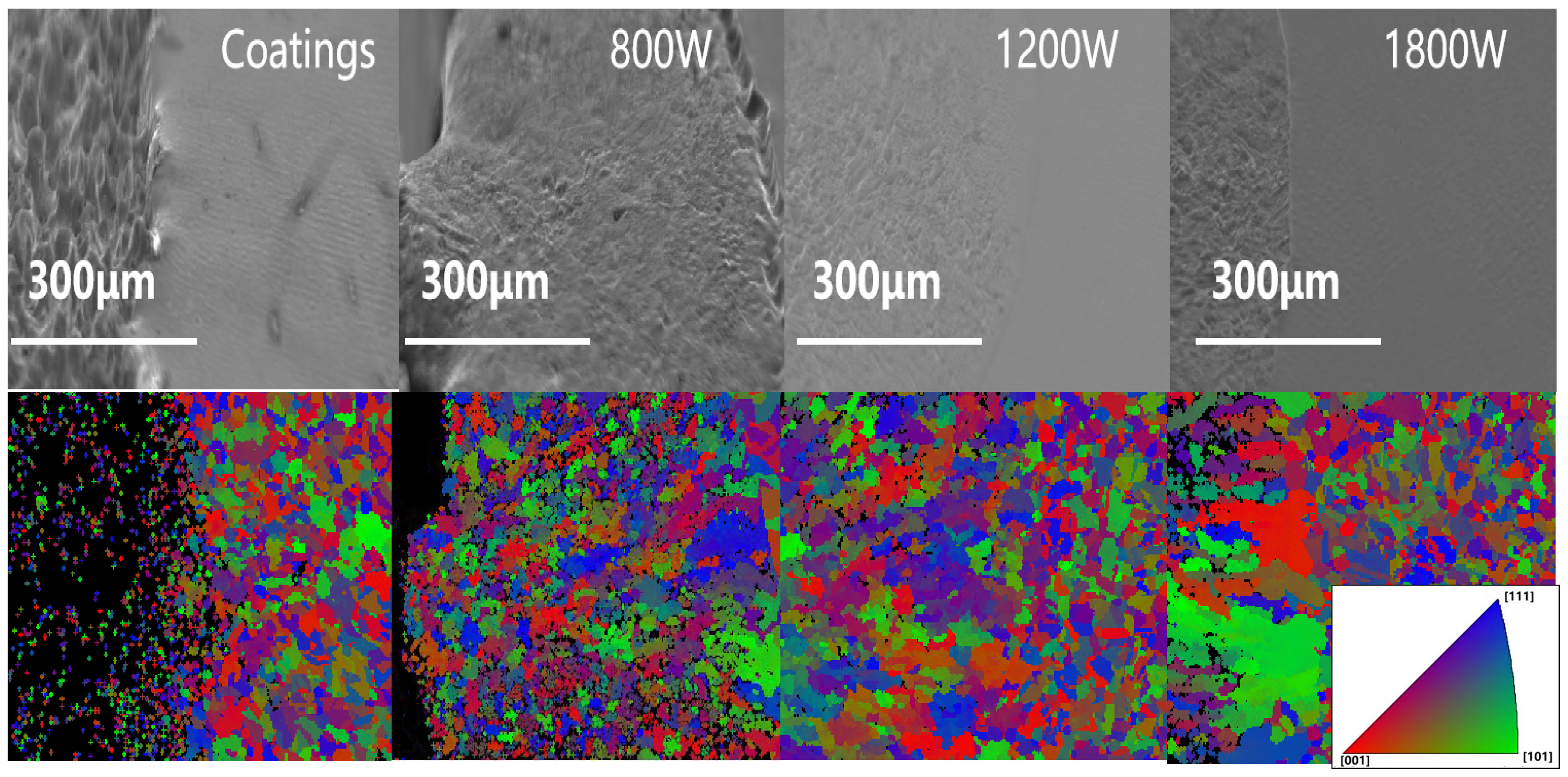
3.2. SEM Morphology and EBSD Analysis

To delve deeper into the microstructural changes prior to and after laser remelting, cross-sectional SEM observations and EBSD analyses were carried out. Figure 2 illustrates that the original coating showed a porous structure with a loose organization and distinct gaps at the coating–substrate interface. Those features are attributed to the particles semi-melting during the thermal spraying process, along with disparate coefficients of thermal expansion and poor wettability between the particles and the metallic binder phase. Furthermore, the primary interaction mechanism involves mechanical interlocking between particles and between the coating and substrate, resulting in a coating with a low density. However, after the laser remelting process, there was a notable increase in the coating density. Such an improvement is evident in the presence of a smooth, curved interface at the lower section of the laser-remelted coating, signifying the establishment of a robust metallurgical bond between the coating and the substrate [35,36].
Figure 2 represents the EBSD grain orientation map of the samples. The original coating’s porous structure limited the EBSD resolution. However, laser remelting improved the density, smoothness, and resolution. After the remelting process, the grain orientations in the coating became more randomized without a predominant alignment. With increased laser power, the grain size within the coating markedly enlarged. Additionally, the distinct coating–substrate interface and non-oriented grain relationship between both sides suggest a nucleation of new grains rather than epitaxial growth [37].

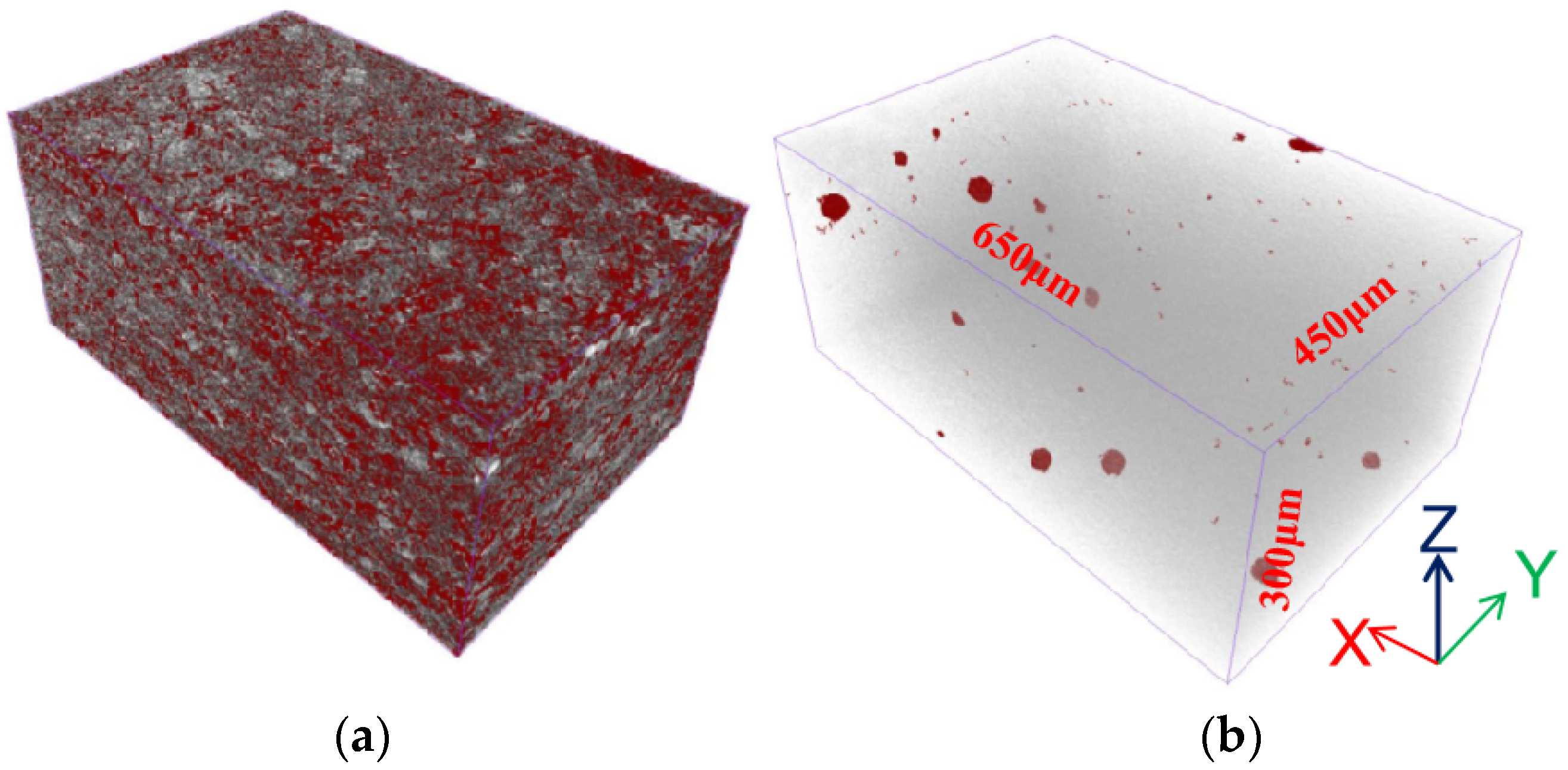
3.3. Porosity Analysis

To ensure that the distribution of pores in the coating prior to and after the laser remelting treatment (at 1200 W) was investigated, an industrial CT was employed to detect the coating, as shown in Figure 3. In the figure, the red areas represent the pores distributed in the coating. A statistical analysis revealed that the porosity of the coating sample stood at 12.41%, and this figure was reduced to 0.7% after the laser remelting treatment. Porosity is known to be an important factor in the corrosion resistance of a coating; a study [38] revealed that increasing the porosity would reduce corrosion resistance. As the mentioned results suggest, laser remelting can significantly reduce the porosity of the coating.

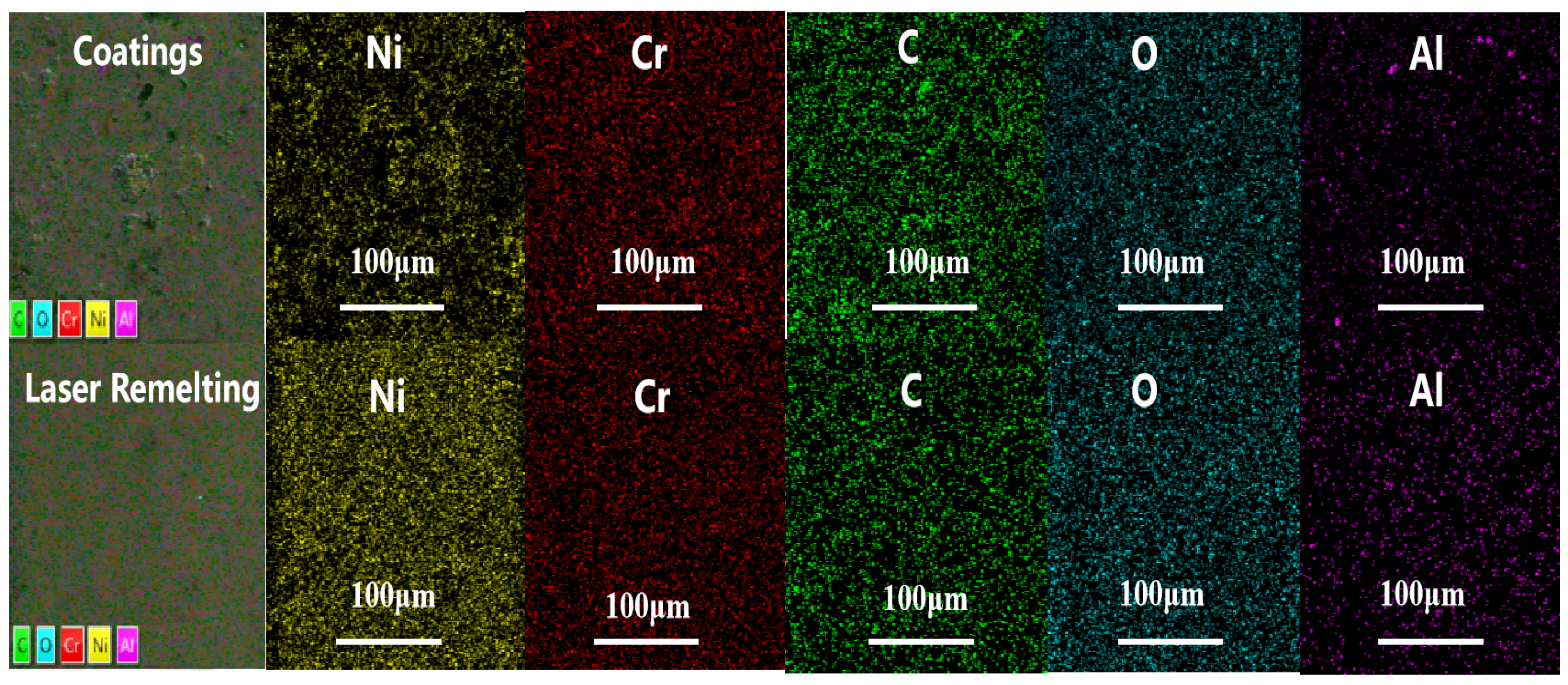
3.4. Analysis of Distribution of Coating Elements

SEM and EDS were employed to analyze the coatings’ surface elements prior to and after the laser remelting treatment (at 1200 W). According to Figure 4, after laser remelting, the distribution of C, Cr, and Ni elements became significantly more uniform compared with that in the pre-remelting condition. The element clustering on the coating surface was notably reduced. Based on these results, it can be inferred that laser remelting optimizes the distribution of the Cr3C2 and NiCr phases, rendering them more uniformly ordered. The uniform distribution of hard particles promotes the coating’s wear resistance [39,40].
However, it is possible that a laser remelting treatment can induce phase transitions within the coating. Therefore, to figure out the impacts of the laser remelting treatment on phase transitions, phase detection on samples prior to and after laser remelting is necessary.

3.5. Hardness Analysis

Hardness, a crucial indicator of wear resistance, was analyzed to help determine what impacts laser remelting has on thermal-sprayed coatings. This analysis aimed to comprehensively describe the changes in coating hardness prior to and after laser remelting. For each sample, random measurements were taken at five points. The results of the average microhardness test for the four samples are represented in Figure 5. The coating’s hardness was 497.3 ± 25.4 HV. At 800 W, it increased to 630 ± 2.45 HV, and at 1200 W, it measured 547.7 ± 4.5 HV. After further increasing the power to 1800 W, the hardness became 477.3 ± 5.2 HV. The data analysis suggested that after laser remelting, the coating hardness initially increases but then decreases with rising laser power. We observed that a higher laser remelting enhances coating density, subsequently boosting hardness. Nevertheless, an excessive thermal input at a higher laser power reduces Cr3C2 within the coating, leading to a decreased hardness. Additionally, the standard deviation of the coating hardness values decreased after the laser remelting, signifying a more uniform hardness distribution.

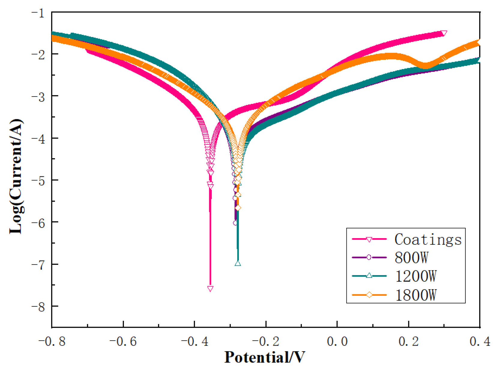
3.6. Electrochemical Corrosion Analysis

Figure 6 depicts the dynamic potential polarization curves of the coatings prior to and after laser remelting in a 5% HCl aqueous solution. In the anodic portion of the electrochemical polarization curve [41,42], a short “passivation-like” stage was observed in the original coating. This should be attributed to the supersaturated dissolution of Cr elements in the binder, which advances the formation of a passive film on surface of the coating [43,44]. Nevertheless, the laser remelting process promoted nucleation and growth of Cr7C3 carbides, with the solubility of Cr elements in the newly formed binder phase decreasing while the surface passivation was hampered. Using the Tafel extrapolation method, this study measured the self-corrosion potential and corrosion current density, and the results are displayed in Table 2. The original coating’s self-corrosion potential was −0.356 V, which shifted positively to around −0.28 V after laser remelting, indicating a reduced corrosion tendency. Meanwhile, the original coating’s corrosion current density stood at 3.301 μA/cm2, lower than the figure prior to laser remelting. The increased coating density and homogenized microstructure led to a decrease in the post-remelting corrosion current density, with reduced interphase galvanic corrosion [45,46]. However, with the laser power increasing to 1800 W, the sample showed an increasing trend in the corrosion current density due to the excessive formation of Cr7C3 at high laser powers, leading to an impeded corrosion resistance.

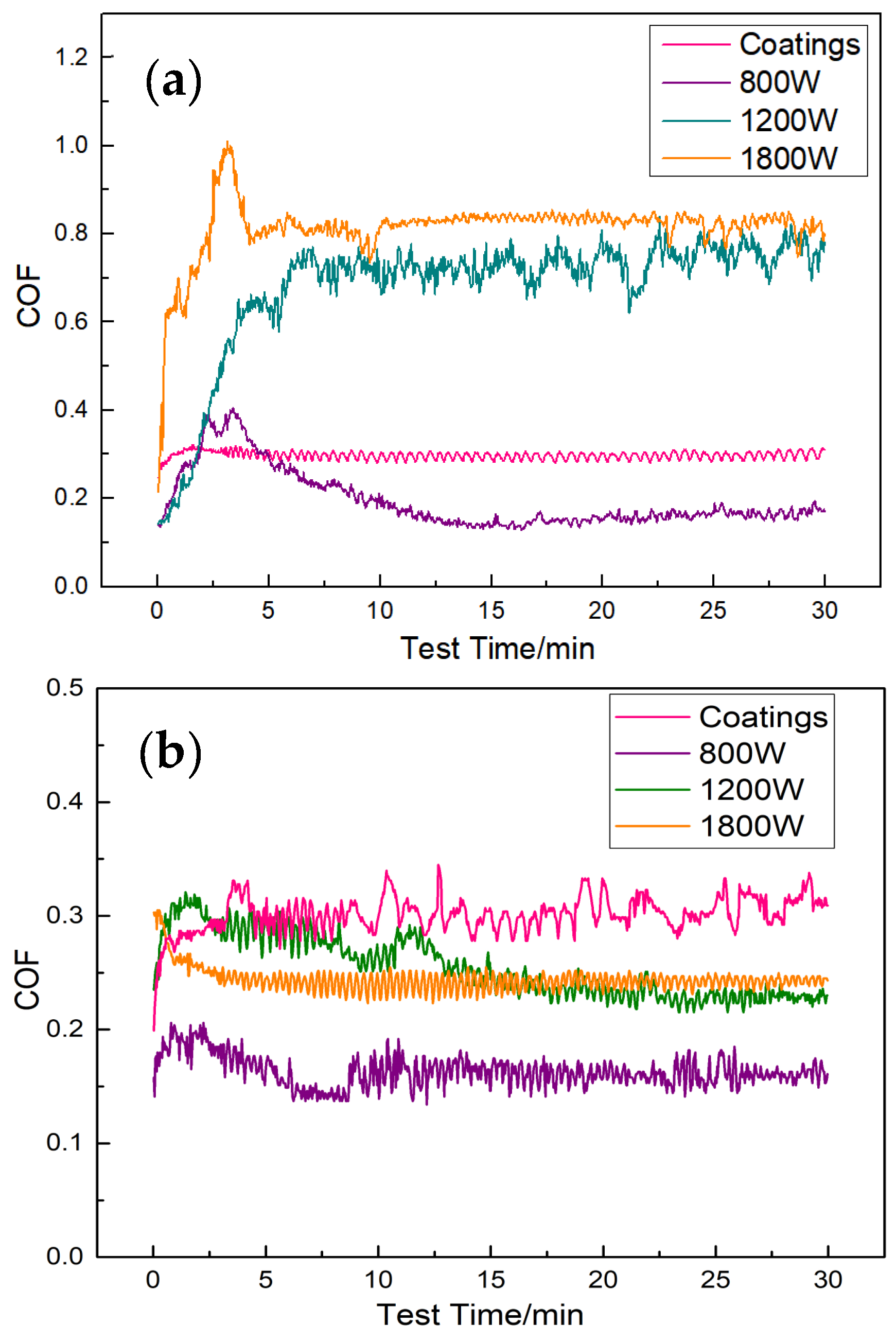
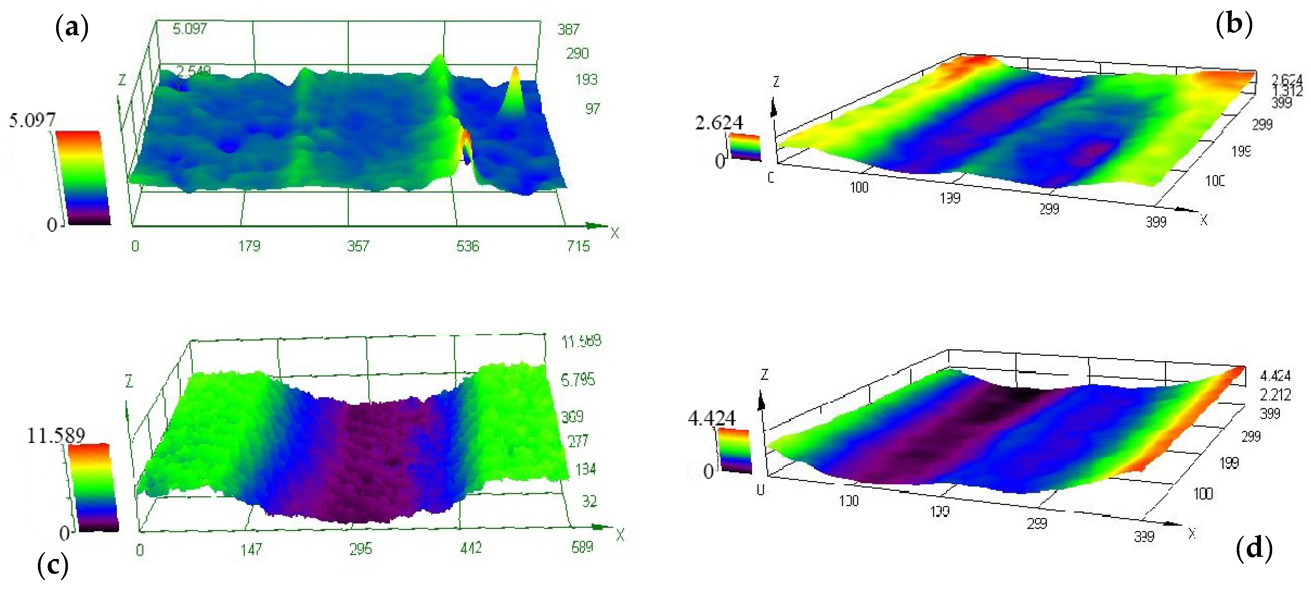
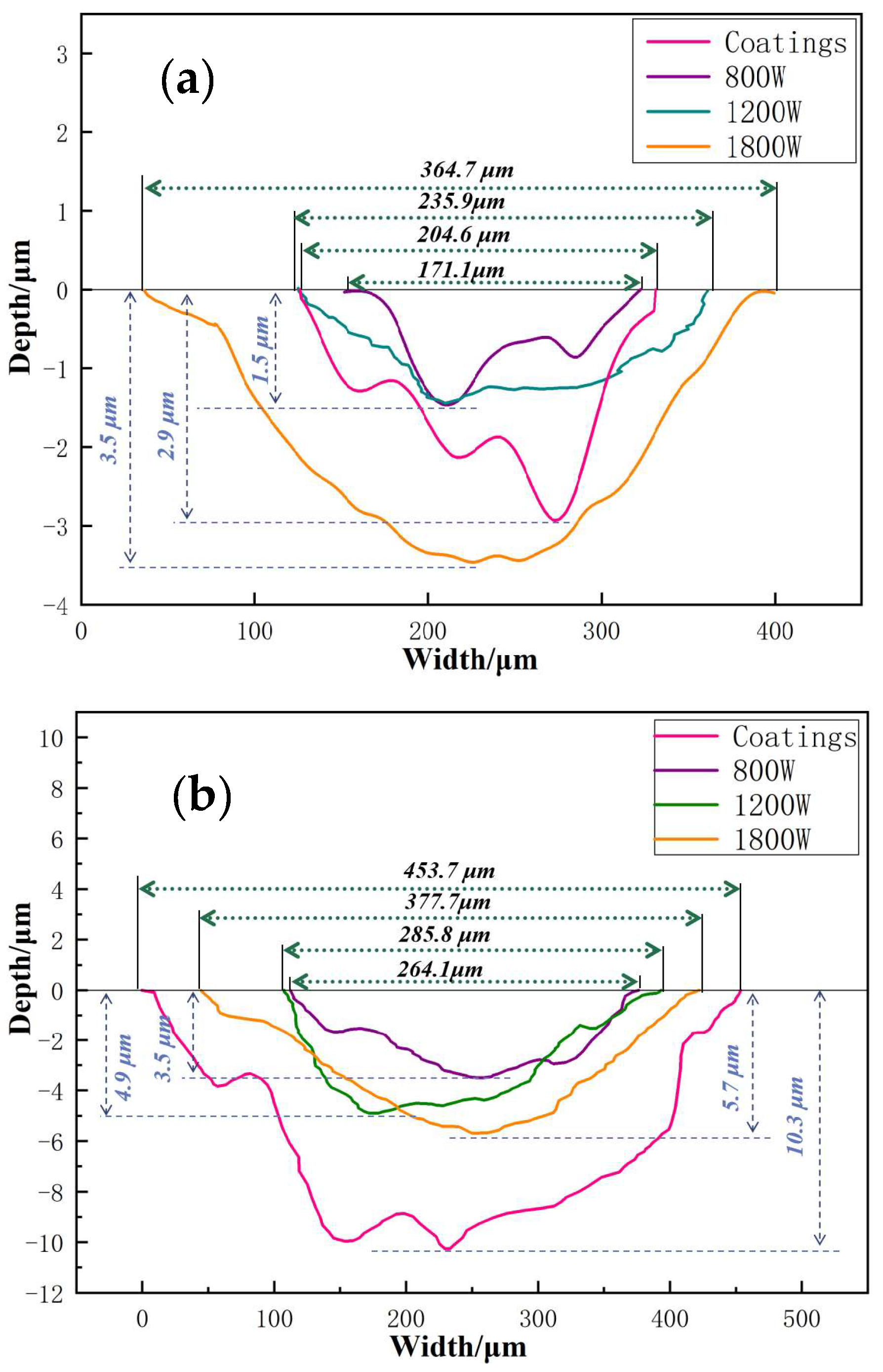
3.7. Friction and Wear Analysis

The friction coefficient works as a key indicator reflecting the frictional state of contact surfaces. Figure 7 depicts the friction coefficient curves for various samples sliding against Al2O3 ceramic balls. As is clearly shown, there was a sharp rise in the friction coefficient at the beginning, but then it decreased and stabilized. During the initial loading phase, the materials only contacted each other at the surface. Due to the smooth sample surface, the abrasive ball interacted with surface micro-protrusions, resulting in a smaller adhesive area and weaker molecular forces. However, as the friction continued, sliding friction between the abrasive and sample surfaces generated wear debris, increasing the surface roughness and wear depth. This enhances the contact area, leading to a sharp friction coefficient increase. As the friction continued, the surfaces continuously adhered to and subsequently experienced shear fracture under shear stress. When the cyclic process eventually reached a dynamic equilibrium, the friction coefficient became stabilized [46,47].
Figure 7a shows the time-varying friction coefficient curve of the specimen in air. This study set the friction coefficient of the original coating at around 0.30. After laser remelting at 800 W, the friction coefficient dramatically rose and then stabilized at around 0.16. With an increasing laser power, the coating’s friction coefficient fluctuated significantly, ranging from 0.65 to 0.75 at 1200 W. At 1800 W, there was a strong fluctuation in the first 5 min. This is because in the coating at 1800 W, the hard particles of Cr3C2 had almost disappeared and its hardness was also lower. Therefore, the grinding ball was pressed deeper at the beginning of the wear test, leading to a larger friction resistance and friction coefficient. Thereafter, as the substrate was cut and plowed, the frictional resistance and coefficient of friction decreased. The final friction coefficient stabilized at around 0.83.
Figure 7b shows the time-varying friction coefficient curve in a 5% hydrochloric acid medium. The friction coefficient of the original coating still remained around 0.3, with fluctuations in its friction coefficient. However, the laser remelted coatings exhibited a reduction in their friction coefficient to varying degrees. The specimen treated at 800 W had a friction coefficient around 0.15, the one treated at 1200 W had a friction coefficient around 0.23, and the specimen treated at 1800 W had a friction coefficient around 0.25. The analysis suggested that within the NiCr-Cr3C2-Al2O3 coating, the presence of Cr3C2 hard particles effectively resists abrasive intrusion, reducing the contact area and thereby lowering the friction coefficient [48]. After a laser remelting treatment at 800 W, the increased coating density led to a notable surface hardness increase, reducing the frictional intrusion resistance and friction coefficient. However, as the laser remelting power increased, defects such as pores appeared in the coating. This suggests that an excessive laser power diminishes the Cr3C2 hard particles, resulting in a decreased coating hardness and elevated friction coefficient due to frictional intrusion. In the corrosive medium, the solution acts as a lubricant, causing an overall decrease in the friction coefficient. However, due to the corrosion causing the continuous spalling of ceramic particles, there was a significant fluctuation in the friction coefficient. In the laser-remelted specimens, the ceramic particles were well-bonded with the NiCr phase, resulting in smaller fluctuations in the friction coefficient.
To elucidate the friction and wear resistance of the different samples, a three-dimensional profile scanner was employed to analyze the wear tracks, as shown in Figure 8. It was evident that the wear surfaces in the corrosive medium environment had deeper furrows and were rougher compared to those in the air environment, indicating that the corrosion significantly accelerated the wear of the coating surface. More importantly, compared with the original coating specimens shown in Figure 8a,c, the laser-remelted specimens exhibited relatively minor damage in both environments (Figure 8b,d). In summary, a reasonable laser remelting treatment can endow the coating with superior anti-corrosive wear performance.
An analysis of the cross-section of the wear track was conducted, as shown in Figure 9. The results in Figure 9a indicate that, in air, the surface wear depth of the original coating was 2.9 μm with a width of 204.6 μm. After the laser remelting treatment at 800 W, the wear depth became 1.5 μm with a width of 171.1 μm. After the laser remelting treatment at 1200 W, the wear depth remained unchanged with a width of 235.9 μm. It was evident that due to the increased hardness, the laser-remelted coating can effectively resist abrasive ball intrusion during reciprocating friction, demonstrating an improved wear resistance. At 1800 W, the reduced Cr3C2 caused a decrease in coating hardness, significantly enlarging the wear track cross-section to a depth of 3.5 μm and width of 364.7 μm.
In the 5% hydrochloric acid medium, the cross sections of the wear tracks on the specimens all increased, as shown in Figure 9b. The original coating had a wear track with a depth of 10.3 μm and a width of 453.7 μm. After 800 W laser remelting, the coating’s surface wear track was 3.5 μm deep with a width of 264.1 μm. The surface wear track of the coating after 1200 W laser remelting had a depth of 4.9 μm and a width of 285.8 μm, while after 1800 W laser remelting, it had a depth of 5.7 μm and a width of 377.7 μm. With the increase in laser power, the trend of change in the depth and width of the wear marks tended to decrease, as shown in the Table 3. Clearly, due to the increase in hardness, more uniform and compact structure, and improved corrosion resistance, the laser-remelted coatings can effectively resist the penetration of the grinding ball during the synergistic process of corrosion and friction, thereby exhibiting better wear resistance.
Figure 10a presents the calculated wear rates for the different samples in air. The original coating registered a wear rate of 8.8 × 10⁻⁶ mm3/Nm. After 800 W laser remelting, the wear rate was reduced to 3.98 × 10⁻⁶ mm3/Nm. At 1200 W, the wear rate dipped to 6.45 × 10⁻⁶ mm3/Nm, and at 1800 W, it rose to 13.5 × 10⁻⁶ mm3/Nm. Those results show that after 800 W laser remelting, the wear rate decreased by 54.8%, indicating a significantly strengthened wear resistance. However, at the excessive laser power of 1800 W, the wear rate swelled by 53.4% compared to the original coating. Those findings reveal that the proper laser power can substantially enhance the coating’s wear resistance.
Figure 10b shows the calculated wear rates of the different specimens in a corrosive medium. The original coating had a wear rate of 19.1 × 10⁻⁶ mm3/Nm. The wear rate of the coating after 800 W laser remelting was 5.9 × 10⁻⁶ mm3/Nm, the 1200 W laser-remelted coating had a wear rate of 7.9 × 10⁻⁶ mm3/Nm, and the 1800 W laser-remelted coating had a wear rate of 13.5 × 10⁻⁶ mm3/Nm. Compared with the wear rate in air, it is known that in a corrosive medium, the wear rate of specimens increases overall. The wear rate of the original coating increased by 117%, the wear rate of the 800 W laser-remelted sample increased by 48%, the 1200 W sample’s wear rate increased by 22%, and the 1800 W sample’s wear rate increased by 15%. The above results indicate that the wear resistance of the coating can be significantly improved with an appropriate laser power, and moreover, the impact of the corrosive medium on the wear rate of the specimens is lessened after laser remelting.

4. Discussion

4.1. Friction Pair EDS Analysis

Using SEM and EDS, a friction pair analysis was carried out after the friction-wear experiments. According to the wear track widths of the friction pair in Figure 11, the wear track width for the original coating was approximately 110 μm, that of the 800 W laser-remelted coating was around 90 μm, that of the 1200 W laser-remelted coating was about 165 μm, and that of the 1800 W laser-remelted coating was around 220 μm. Typically, narrower widths mean a better wear performance.
Based on the EDS analysis of the friction pair surfaces of the samples, the predominant element on the coating and the 800 W and 1200 W sample wear tracks was C that primarily originated from the hard Cr3C2 particles. However, in the 1800 W sample’s wear track, there was not only a small amount of C but also a significant amount of Ni, which were mainly formed from the bonding phase. This was further proved by the EDS results that showed that the presence of Cr3C2 hard particles effectively inhibited the intrusion of the friction pair. At 800 W and 1200 W, the friction pair mainly experienced wear on the Cr3C2 particles, without damaging the bonding phase. However, the excessive 1800 W laser power resulted in a reduction in Cr3C2 particles, leading to the contact and disruption of the bonding phase during friction.

4.2. XRD Analysis

To achieve phase identification, an X-ray diffraction analysis on the samples was carried out with the help of Jade 6.5 software. The XRD diffraction patterns of the coatings prior to and after the laser remelting treatment are shown in Figure 12. From the graph, it can be clearly seen that the coating samples primarily consisted of NiCr and Cr3C2 phases. After laser remelting at 800 W, a minor Cr7C3 phase emerged. Subsequent to laser remelting at 1200 W, Cr3C2 decreased while Cr7C3 increased. Upon reaching a laser power of 1800 W, the Cr3C2 phase in the sample was nearly eliminated. A high-temperature laser beam can easily lead to the melting of carbides and the NiCr binder phase, leading to a Ni-Cr-C mixed liquid phase. As the laser beam leaves the molten pool, rapid solidification occurs. During the solidification process, carbide phases crystallize earlier because of their higher melting points compared with nickel-based alloy phases. However, rapid cooling inhibits Cr3C2 nucleation, resulting in the formation of Cr7C3 [49], which is brought about by Cr-C supersaturation. Due to the lower melting point and hardness of Cr7C3 than Cr3C2, its presence diminishes the wear resistance and oxidation resistance [50,51].
Laser remelting can significantly improve the density of coatings and the uniform distribution of elements within the coatings. These changes are conducive to the improvement of the wear resistance of the coatings. However, an inappropriately high laser power leads to a severe decomposition in the Cr3C2 particles in the coatings, resulting in a decrease in coating hardness and wear performance. Therefore, keeping the laser power at an appropriate level is essential in the improvement of the coating’s wear resistance.

4.3. Mechanism Analysis

The previous results indicate that laser remelting of the coating can enhance the coatings’ wear resistance in both air and corrosive environments. Figure 13 presents the strengthening mechanism of this method. As can be seen from the Figure 13a, the coating consists of a matrix phase and Cr3C2 hard particles. The original coating surface has a high porosity rate, and the bonding force between the matrix phase and Cr3C2 particles is weak. In a corrosive environment, the corrosive medium can penetrate into the pores formed by thermal spraying and the gaps between the Cr3C2 particles and the matrix phase, causing corrosion. The corrosion process weakens the bond between the Cr3C2 particles and the matrix phase, leading to the detachment of Cr3C2 particles during friction, which deteriorates the friction performance. Figure 13b shows the laser remelted coating; after laser remelting, the pores in the coating disappear, and the microstructure becomes more compact. The bond between the matrix phase and the Cr3C2 particles in the coating is improved. During the process of corrosion and friction, it is difficult for the Cr3C2 particles to detach; therefore, the corrosion resistance and friction performance of the coating are both enhanced compared to the original coating. As shown in Figure 13c, under an excessively high laser power, the hard Cr3C2 particles in the remelted coating can transform into lower hardness Cr7C3 particles, which compromises the coating’s ability to resist intrusion from the Al2O3 spheres. Moreover, during the friction process, the lower hardness Cr7C3 particles can become fragmented into smaller particles due to abrasive interactions with the Al2O3 spheres. This results in increased surface roughness, which in turn, increases the friction coefficient and decreases the friction performance [49].

5. Conclusions

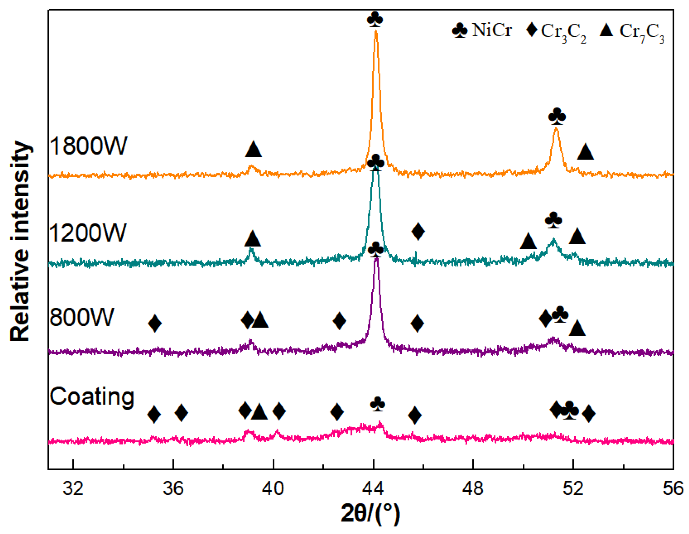
  • Laser remelting promotes the re-nucleation and uniform distribution of carbides within the Cr3C2-Al2O3-NiCr coating, leading to an increased microstructure density and enhanced hardness. However, an excessive laser power inhibits the nucleation of Cr3C2, resulting in the formation of Cr7C3 and a subsequent reduction in hardness.
  • The laser-remelted Cr3C2-Al2O3-NiCr coating exhibits a denser microstructure and enhanced uniformity, effectively mitigating the galvanic corrosion that occurs between the binder and carbides, thereby improving corrosion resistance.
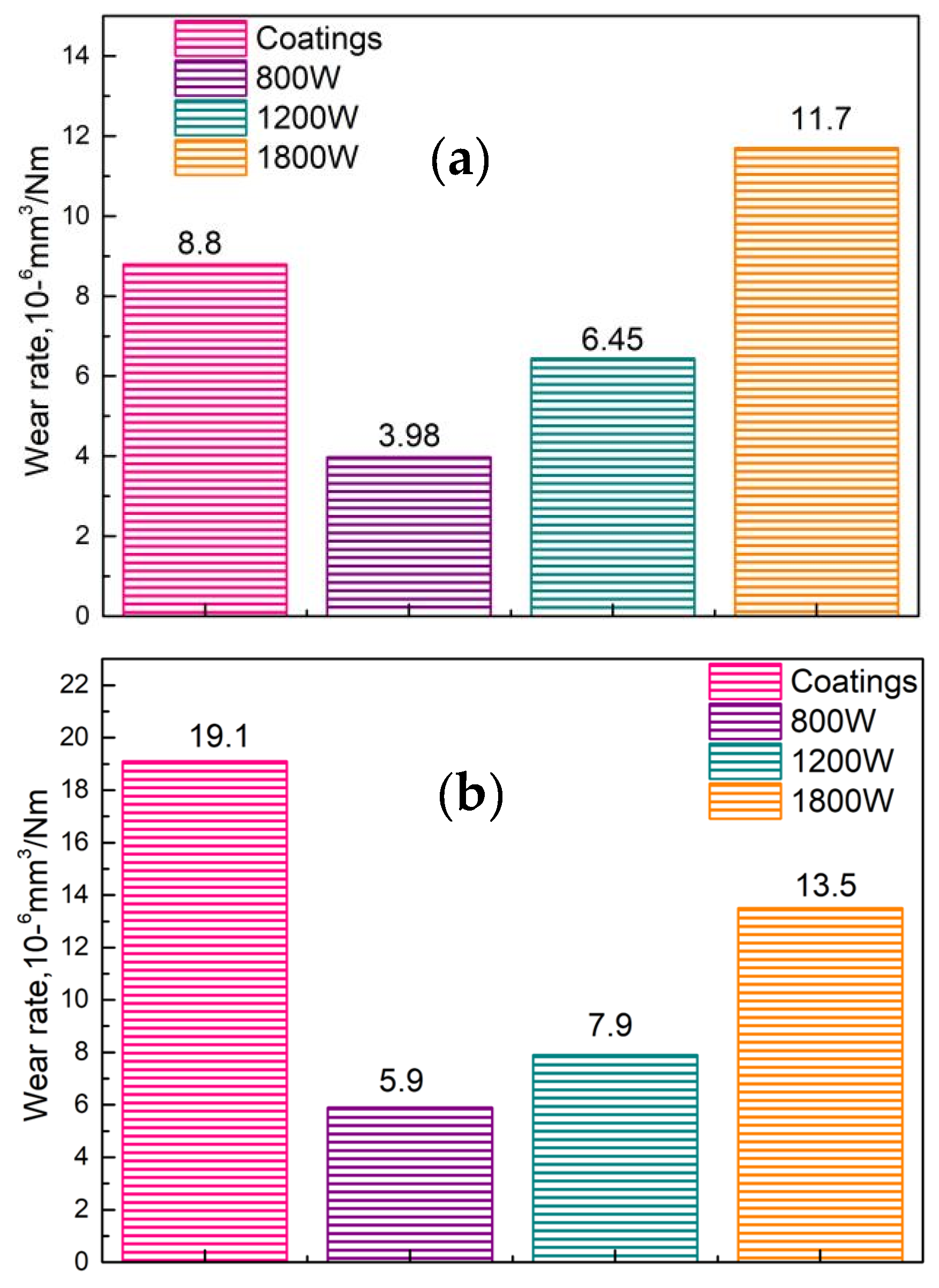
  • The laser power affects the wear performance of the laser-remelted Cr3C2-Al2O3-NiCr coating. At 800 W, the wear rate decreased by 54.8% compared to the original coating, whereas at 1800 W, the wear rate increased by 53.4% compared to the original one.
  • The wear rate of the Cr3C2-Al2O3-NiCr coating in a 5% HCl solution increased compared to that in air. The wear rate of the original coating increased by 117%, that of the sample remelted with an 800 W laser increased by 48%, that of the 1200 W sample increased by 22%, and that of the 1800 W sample increased by 15%.

Author Contributions

Experiments and writing—original draft, F.L.; Study design, F.L. and C.Z.; Writing—review and editing, C.Z.; Supervision, Y.L. and Q.P. All authors have read and agreed to the published version of the manuscript.

Funding

This work was supported by the Shaanxi Province Innovation Capability Support Plan (Grant No.2023-CX-TD-50).

Institutional Review Board Statement

Not applicable.

Informed Consent Statement

Not applicable.

Data Availability Statement

Data presented in this article are available upon request from the corresponding author.

Conflicts of Interest

Authors Yan Li and Qingtao Pang was employed by the company ShanMei Group New Energy Hydrogen Energy Technology Co., Ltd. The remaining authors declare that the research was conducted in the absence of any commercial or financial relationships that could be construed as a potential conflict of interest.

References

  1. Wang, Y.; Liu, H.; Yu, G.; Hou, J.; Zeng, C. Electrochemical study of the corrosion of a Ni-based alloy GH3535 in molten (Li, Na, K)F at 700 degrees C. J. Fluor. Chem. 2015, 178, 14–22. [Google Scholar] [CrossRef]
  2. Saber, D.; Emam, I.S.; Abdel-Karim, R. High temperature cyclic oxidation of Ni based superalloys at different temperatures in air. J. Alloys Compd. 2017, 719, 133–141. [Google Scholar] [CrossRef]
  3. Ma, X.F.; Duan, Z.; Shi, H.J. Fatigue and fracture behavior of nickel-based superalloy Inconel 718 up to the very high cycle regime. J. Zhejiang Univ.-Sci. A 2010, 11, 727–737. [Google Scholar] [CrossRef]
  4. Behera, A.; Sahoo, A.K. Wear behaviour of Ni based superalloy: A review. Mater. Today Proc. 2020, 33, 5638–5642. [Google Scholar] [CrossRef]
  5. Wu, P.; Du, H.M.; Chen, X.L.; Li, Z.Q.; Bai, H.L.; Jiang, E.Y. Influence of WC particle behavior on the wear resistance properties of Ni–WC composite coatings. Wear 2004, 257, 142–147. [Google Scholar] [CrossRef]
  6. Wei, C.; Wang, Z.; Chen, J. Sulfuration corrosion failure analysis of Inconel 600 alloy heater sleeve in high-temperature flue gas. Eng. Fail. Anal. 2022, 135, 106111. [Google Scholar] [CrossRef]
  7. Li, W.J.; Lin, K.L. Strengthening of Inconel 600 alloy with electric current stressing. Materialia 2023, 27, 101666. [Google Scholar] [CrossRef]
  8. Prem Kumar, M.; Arivazhagan, N.; Chiranjeevi, C.; Raja Sekhar, Y.; Babu, N.; Manikandan, M. Effect of Molten Binary Salt on Inconel 600 and Hastelloy C-276 Superalloys for Thermal Energy Storage Systems: A Corrosion Study. J. Mater. Eng. Perform. 2023, 1–14. [Google Scholar] [CrossRef]
  9. Tatone, O.S.; Meindl, P.; Taylor, G.F. Steam Generator Tube Performance: Experience with Water-Cooled Nuclear Power Reactors during 1983 and 1984; No. AECL-9107; Atomic Energy of Canada Ltd.: Chalk River, ON, Canada, 1986. [Google Scholar]
  10. Morita, T.; Hirano, Y.; Asakura, K.; Kumakiri, T.; Ikenaga, M.; Kagaya, C. Effects of plasma carburizing and DLC coating on friction-wear characteristics, mechanical properties and fatigue strength of stainless steel. Mater. Sci. Eng. A 2012, 558, 349–355. [Google Scholar] [CrossRef]
  11. Fazlalipour, F.; Niki Nushari, M.; Shakib, N.; Shokuhfar, A. Comparative Tribological Behavior of V(N,C) and VC Diffusion Coatings. Defect Diffus. Forum 2010, 297–301, 1183–1189. [Google Scholar] [CrossRef]
  12. Kagiyama, A.; Terakado, K.; Urao, R. Effect of nitriding and TiN coating temperatures on the corrosion resistance of the combined surface modification layer. Surf. Coat. Technol. 2003, 169, 397–400. [Google Scholar] [CrossRef]
  13. Deshmukh, D.D.; Kalyankar, V.D. Recent status of overlay by plasma transferred arc welding technique. Int. J. Mater. Prod. Technol. 2018, 56, 23–83. [Google Scholar] [CrossRef]
  14. Tian, H.L.; Guo, M.Q.; Wang, C.L.; Tang, Z.H.; Cui, Y.J. Tribological behaviour of a self-lubricated GO/WC–12Co thermal spray coating. Surf. Eng. 2018, 34, 762–770. [Google Scholar] [CrossRef]
  15. Lin, L.; Li, G.-L.; Wang, H.-D.; Kang, J.-J.; Xu, Z.-L.; Wang, H.-J. Structure and wear behavior of NiCr-Cr3C2 coatings sprayed by supersonic plasma spraying and high velocity oxy-fuel technologies. Appl. Surf. Sci. 2015, 356, 383–390. [Google Scholar] [CrossRef]
  16. Liu, Q.; Bai, Y.; Wang, H.D.; Ma, G.Z.; Liu, M.; Chu, C.Y.; Sun, Y.W.; Fan, W.; Ding, F.; Zhao, B.; et al. Microstructural evolution of carbides and its effect on tribological properties of SAPS or HVOF sprayed NiCr–Cr3C2 coatings. J. Alloys Compd. 2019, 803, 730–741. [Google Scholar] [CrossRef]
  17. Liu, Q.; He, T.; Guo, W.Y.; Bai, Y.; Ma, Y.S.; Chang, Z.D.; Liu, H.B.; Zhou, Y.X.; Ding, F.; Sun, Y.W.; et al. Tribological behavior of SAPS sprayed Al2O3-TiO2 and NiCr-Cr3C2 coatings under severe load conditions. Surf. Coat. Technol. 2019, 370, 362–373. [Google Scholar] [CrossRef]
  18. Kuruba, M.; Gaikwad, G.; Natarajan, J.; Koppad, P.G. Effect of carbon nanotubes on microhardness and adhesion strength of high-velocity oxy-fuel sprayed NiCr–Cr3C2 coatings. Proc. Inst. Mech. Eng. Part L J. Mater. Des. Appl. 2022, 236, 86–96. [Google Scholar] [CrossRef]
  19. Liu, J.; Wang, L.; Li, F.; Ran, X.; Peng, X. Life cycle Inventory of NiCrAl/NiCr-Cr3C2 Composite Coatings for Plasma Spraying Process. Procedia Manuf. 2020, 43, 559–566. [Google Scholar] [CrossRef]
  20. Temmler, A.; Willenborg, E.; Wissenbach, K. Design surfaces by laser remelting. Phys. Procedia 2011, 12, 419–430. [Google Scholar] [CrossRef]
  21. Mateos, J.; Cuetos, J.M.; Vijande, R.; Fernández, E. Tribological properties of plasma sprayed and laser remelted 75/25 Cr3C2/NiCr coatings. Tribol. Int. 2001, 34, 345–351. [Google Scholar] [CrossRef]
  22. Chen, H.; Xu, C.; Zhou, Q.; Hutchings, I.M.; Shipway, P.H.; Liu, J. Micro-scale abrasive wear behaviour of HVOF sprayed and laser-remelted conventional and nanostructured WC-Co coatings. Wear 2005, 258, 333–338. [Google Scholar] [CrossRef]
  23. Wang, H.; Cheng, Y.; Yang, J.; Wang, Q. Influence of laser remelting on organization, mechanical properties and corrosion resistance of Fe-based amorphous composite coating. Surf. Coat. Technol. 2021, 414, 127081. [Google Scholar] [CrossRef]
  24. Zhou, S.; Xu, Y.; Liao, B.; Sun, Y.; Dai, X.; Yang, J.; Li, Z. Effect of laser remelting on microstructure and properties of WC reinforced Fe-based amorphous composite coatings by laser cladding. Opt. Laser Technol. 2018, 103, 8–16. [Google Scholar] [CrossRef]
  25. Jin, B.; Zhang, N.; Yin, S. Strengthening behavior of AlCoCrFeNi(TiN) high-entropy alloy coatings fabricated by plasma spraying and laser remelting. J. Mater. Sci. Technol. 2022, 121, 163–173. [Google Scholar] [CrossRef]
  26. Qian, J.; Zhang, J.; Li, S.; Wang, C. Study on laser cladding NiAl/Al2O3, coating on magnesium alloy. Rare Metal Mater. Eng. 2013, 42, 466–469. [Google Scholar] [CrossRef]
  27. Zhao, Y.; Wu, X.; Du, H.; Shangguan, X.; He, W. Influence of different laser re-melting paths on the microstructure of a spray coating: Defect prevention and tribological properties. Surf. Coat. Technol. 2019, 367, 11–18. [Google Scholar] [CrossRef]
  28. Zhang, X.-Q.; Gong, W.-B.; Liu, Y.-D. Microstructure and properties of laser remelted nickel based alloy composite coating. Weld 2007, 2, 46–48. [Google Scholar]
  29. García, J.R.; Fernandez, J.E.; Cuetos, J.M.; Costales, F.G. Fatigue effect of WC coatings thermal sprayed by HVOF and laser treated, on medium carbon steel. Eng. Fail. Anal. 2011, 18, 1750–1760. [Google Scholar] [CrossRef]
  30. Yi, P.; Mostaghimi, J.; Pershin, L.; Xu, P.; Zhan, X.; Jia, D.; Liu, Y. Effects of laser surface remelting on the molten salt corrosion resistance of yttria-stabilized zirconia coatings. Ceram. Int. 2018, 44, 22645–22655. [Google Scholar] [CrossRef]
  31. Guo, H.F.; Tian, Z.J.; Huang, Y.H. Laser surface remelting of WC–12Co coating: Finite element simulations and experimental analyses. Mater. Sci. Technol. 2016, 32, 813–822. [Google Scholar] [CrossRef]
  32. Yilbas, B.S.; Arif, A.F.M. Residual stress analysis for HVOF diamalloy 1005 on Ti–6Al–4V alloy. Surf. Coat. Technol. 2007, 202, 559–568. [Google Scholar] [CrossRef]
  33. Li, F.; Zhang, C.; Pang, Q.; Fang, G.; Xu, G. Effect of High-Energy Shot Peening on Properties of High-Velocity Oxygen-Fuel Spraying. Coatings 2023, 13, 872. [Google Scholar] [CrossRef]
  34. Wang, X.; You, G.; Yang, Z.; Long, S. Pore formation mechanism in laser local re-melted areas of die cast magnesium alloy AZ91D. Rare Met. Mater. Eng. 2012, 41, 2144–2148. [Google Scholar]
  35. Mateos, J.; Cuetos, J.M.; Fernández, E.; Vijande, R. Tribological behaviour of plasma-sprayed WC coatings with and without laser remelting. Wear 2000, 239, 274–281. [Google Scholar] [CrossRef]
  36. Ji, X.; Gu, P.; Wang, Z.; Tang, Q.; Li, Z. Effect of laser remelting on slurry erosion and corrosion properties of arc-sparyed Fe-based amorphous-comtaining coatings. Surf. Technol. 2019, 48, 68–74. [Google Scholar]
  37. Zhang, K.; Zou, J.; Li, J.; Yu, Z. EBSD characterization of the laser remelted surface layers in a commercially pure Mg. J. Mater. Sci. Technol. 2014, 30, 263–267. [Google Scholar] [CrossRef]
  38. Kawakita, J.; Kuroda, S.; Kodama, T. Evaluation of through-porosity of HVOF sprayed coating. Surf. Coat. Technol. 2003, 166, 17–23. [Google Scholar] [CrossRef]
  39. Van Acker, K.; Vanhoyweghen, D.; Persoons, R.; Vangrunderbeek, J. Influence of tungsten carbide particle size and distribution on the wear resistance of laser clad WC/Ni coatings. Wear 2005, 258, 194–202. [Google Scholar] [CrossRef]
  40. Qunshuang, M.; Yajiang, L.; Juan, W. Effects of Ti addition on microstructure homogenization and wear resistance of wide-band laser clad Ni60/WC composite coatings. Int. J. Refract. Met. Hard Mater. 2017, 64, 225–233. [Google Scholar] [CrossRef]
  41. Chukwuike, V.I.; Echem, O.G.; Prabhakaran, S.; AnandKumar, S.; Barik, R.C. Laser shock peening (LSP): Electrochemical and hydrodynamic investigation of corrosion protection pre-treatment for a copper surface in 3.5% NaCl medium. Corros. Sci. 2021, 179, 109156. [Google Scholar] [CrossRef]
  42. Sadeghimeresht, E.; Markocsan, N.; Nylén, P.; Björklund, S. Corrosion performance of bi-layer Ni/Cr2C3–NiCr HVAF thermal spray coating. Appl. Surf. Sci. 2016, 369, 470–481. [Google Scholar] [CrossRef]
  43. Stellwag, B. The mechanism of oxide film formation on austenitic stainless steels in high temperature water. Corros. Sci. 1998, 40, 337–370. [Google Scholar] [CrossRef]
  44. Zhang, B.; Hao, S.; Wu, J.; Li, X.; Li, C.; Di, X.; Huang, Y. Direct evidence of passive film growth on 316 stainless steel in alkaline solution. Mater. Charact. 2017, 131, 168–174. [Google Scholar] [CrossRef]
  45. Chong, K.; Zou, Y.; Wu, D.; Tang, Y.; Zhang, Y. Pulsed laser remelting supersonic plasma sprayed Cr3C2-NiCr coatings for regulating microstructure, hardness and corrosion properties. Surf. Coat. Technol. 2021, 418, 127258. [Google Scholar] [CrossRef]
  46. Wang, W.; Du, M.; Zhang, X.; Geng, M. Microstructure and Tribological Properties of WC-Ni Matrix Cermet Coatings Prepared by Electrospark Deposition on H13 Steel Substrate. Acta Metall. Sin. 2021, 57, 1048–1056. [Google Scholar]
  47. Blau, P.J. The significance and use of the friction coefficient. Tribol. Int. 2001, 34, 585–591. [Google Scholar] [CrossRef]
  48. Roy, M.; Venkataraman, B.; Bhanuprasad, V.V.; Mahajan, Y.R.; Sundararajan, G. The effect of participate reinforcement on the sliding wear behavior of aluminum matrix composites. Metall. Trans. A 1992, 23, 2833–2847. [Google Scholar] [CrossRef]
  49. Matthews, S. Compositional Development as a Function of Spray Distance in Unshrouded/Shrouded Plasma-Sprayed Cr3C2-NiCr Coatings. J. Therm. Spray Technol. 2015, 24, 515–533. [Google Scholar] [CrossRef]
  50. Sun, G.; Zhang, Y.; Liu, C.; Luo, K.; Tao, X.; Li, P. Microstructure and wear resistance enhancement of cast steel rolls by laser surface alloying NiCr–Cr3C2. Mater. Des. 2010, 31, 2737–2744. [Google Scholar] [CrossRef]
  51. Zhang, D.; Zhang, X. Laser cladding of stainless steel with Ni–Cr3C2 and 51.Ni–WC for improving erosive–corrosive wear performance. Surf. Coat. Technol. 2005, 190, 212–217. [Google Scholar] [CrossRef]
Figure 1. Cross-sectional OM.
Coatings 14 00325 g001
Figure 2. Cross-sectional SEM and EBSD.
Coatings 14 00325 g002
Figure 3. Porosity detection by CT. (a) Coating, (b) coating + remelting.
Coatings 14 00325 g003
Figure 4. Surface SEM and EDS.
Coatings 14 00325 g004
Figure 5. Results of the hardness test.
Coatings 14 00325 g005
Figure 6. Taffel curve for the different coatings.
Coatings 14 00325 g006
Figure 7. Curves of COF vs. test time (a) in air and (b) in the corrosive medium.
Coatings 14 00325 g007
Figure 8. Three-dimensional trace after friction test: (a) coatings in air; (b) laser remelting in the air; (c) coatings in the corrosive medium; (d) laser remelting in the corrosive medium.
Coatings 14 00325 g008
Figure 9. Profiles of wear scar depth (a) in air and (b) in the corrosive medium.
Coatings 14 00325 g009
Figure 10. Wear test results (a) in the air and (b) in the corrosive medium.
Coatings 14 00325 g010
Figure 11. Surface morphology and EDS results of grinding ball corresponding to substrate and coating after the friction experiment.
Coatings 14 00325 g011
Figure 12. XRD diffraction patterns of different coatings.
Coatings 14 00325 g012
Figure 13. Schematic diagram of strengthening mechanism: (a) original coating, (b) remelted coating, (c) over-powered remelted coating.
Coatings 14 00325 g013
Table 1. Chemical composition of INCONEL600 alloy.
ElementCMnSiPSCrNiCuFe
wt.%≤0.15≤1.00≤0.50≤0.030≤0.01514.0–17.071.0–78.0≤0.506.0–10.0
Table 2. Fitting results of polarization curves.
SampleI0/(μA/cm2)E0/V
Coatings3.301−0.356
800 W1.641−0.285
1200 W1.467−0.279
1800 W2.314−0.281
Table 3. Comparison table of friction depth and width in air versus 5% hydrochloric acid solution.
SpecimenDepth/Width (in Air)Depth/Width (in the 5% Hydrochloric Acid Medium)Rate of Change (in the Medium vs. in Air) Depth/Width
Coatings2.9 μm/204.6 μm10.3 μm/453.7 μm255%/122%
800 W1.5 μm/171.1 μm3.5 μm/264.1 μm133%/54%
1200 W1.6 μm/235.9 μm4.9 μm/285.8 μm206%/21%
1800 W3.5 μm/364.7 μm.5.7 μm/377.7 μm.63%/4%
Disclaimer/Publisher’s Note: The statements, opinions and data contained in all publications are solely those of the individual author(s) and contributor(s) and not of MDPI and/or the editor(s). MDPI and/or the editor(s) disclaim responsibility for any injury to people or property resulting from any ideas, methods, instructions or products referred to in the content.

