Article

Wear Behavior Assessment of New Wire-Arc Additively Manufactured Surfaces on AA6061 and AA5086 Alloys through Multi-Walled Carbon Nanotubes and Ni Particles Inducement

by
Muhammad Muzamil
1,*,
Syed Amir Iqbal
2,
Muhammad Naveed Anwar
1,
Muhammad Samiuddin
3,
Junzhou Yang
4 and
Muhammad Ahmed Raza
1
1
Department of Mechanical Engineering, NED University of Engineering & Technology, Karachi 75270, Pakistan
2
Department of Industrial and Manufacturing Engineering, NED University of Engineering & Technology, Karachi 75270, Pakistan
3
Department of Metallurgical Engineering, NED University of Engineering & Technology, Karachi 75270, Pakistan
4
School of Metallurgy Engineering, Xi’an University of Architecture and Technology, Xi’an 710075, China
*
Author to whom correspondence should be addressed.
Coatings 2024, 14(4), 429; https://doi.org/10.3390/coatings14040429
Submission received: 18 December 2023 / Revised: 18 March 2024 / Accepted: 25 March 2024 / Published: 3 April 2024
(This article belongs to the Special Issue Tribological and Mechanical Properties of Coatings)

Abstract

:
This study investigates the new surface development on AA6061 and AA5086 alloys considering the wire-arc additive manufacturing technique as a direct energy deposition (DED) process of wire. Two different quantities of MWCNTs, i.e., 0.01 (low) and 0.02 (high) g, with a constant nickel (Ni) weight (0.2 g) were pre-placed in the created square patterns. ER4043 filler was used as a wire for additive deposition, and an arc was generated through a tungsten inert gas (TIG) welding source. Furthermore, hardness and pin-on-disk wear-testing methods were employed to measure the changes at the surfaces with the abovementioned inducements. This work was designed to illustrate the hardness and the offered wear resistance in terms of mass loss of the AA6061 and AA5086 aluminum alloys with the function of nano-inducements. Two sliding distance values of 500 m and 600 m were selected for the wear analysis of mass loss from tracks. A maximum increase in hardness for AA6061 and AA5086 alloys was observed in the experiments, with average values of 70.76 HRB and 74.86 HRB, respectively, at a high mass content of MWCNTs. Moreover, the tribological performance of the modified surfaces improved with the addition of MWCNTs with Ni particles in a broader sense; the modified surfaces performed exceptionally well for AA5086 compared to AA6061 with 0.02 and 0.01 g additions, respectively. The system reported a maximum of 38.46% improvement in mass loss for the AA5086 alloy with 0.02 g of MWCNTs. Moreover, the morphological analysis of the developed wear tracks and the mechanism involved was carried out using scanning electron microscope (SEM) images.

1. Introduction

Among the available light metals, aluminum and its alloys are of great interest to a wide variety of industries, including automobile, aerospace, medical, electrical, and electronic appliances, owing to good mechanical and physical attributes such as their low density, high strength-to-weight ratio, good conductivity, formability, and high recyclability [1]. However, aluminum’s pure form is not suitable for structural and general engineering applications and must be strengthened by the addition of Si, Mg, Mn, Cu, and Zn, commonly used for alloy development [2].
From the available alloys, AA6061 and AA5086 are quite popular among domestic and international working and research units. AA6061 contains Si and Mg as the major alloying elements, with attributes of good weldability and machinability and considerable applications in structural engineering such as bike frames, aircraft, and automobile parts. In contrast, AA5086 is a high-strength alloy containing Mn, Mg, and Cr as the major alloying elements, with excellent corrosion resistance, and is often found in applications in the marine and shipbuilding industries [3].
Utilizing these lightweight aluminum alloys and replacing the ferrous metals in moving parts for low energy consumption and easy recycling holds considerable potential, but researchers must ensure acceptable or improved wear resistance surfaces. However, despite the abovementioned good physical attributes, aluminum alloys suffer from poor tribological behavior [4] that hinders their usage for many applications. The tribological and surface characteristics of the fabricated components play a significant role in considering the in-service performance of these alloys for components that have a mechanically rotating and sliding exposure, causing them to be affected by wear and tear.
Several methods are available to improve the surface tribological characteristics of the alloys based on the function and application required, and laser surface alloying (LSA), which is considered an extensive process, has been popular in this decade among the research community [5]. The mixture of alloying elements or nanoparticles can be added in two ways, either by injecting the mixture directly into the melt pool or by creating a preplaced coating mixture that will be scanned over the deposited surface by laser beam irradiation [6]. LSA performance can be assessed through modifications in surface properties such as hardness and wear resistance, and several authors have carried out their work using the same integrated sequence.
Initially, SiC hard ceramic particles were quite well known for combating wear and improving the mechanical behavior of aluminum alloys, and several researchers have reported their utilization [7,8,9]. Jiru et al. [10] developed a layer on a pure aluminum plate with TiO2 and SiC particles for improved microhardness behavior with LSA. Later, further studies highlighted that SiC has the ability to dissolve and react with aluminum to form Al4C3, which is brittle in nature [11]. Based on that, researchers have reoriented their focus and started utilizing Ti, Ni, and SiC particles in combination with others. Mabhali et al. [12] performed LSA on AA1200 with a combination of three alloying elements, SiC, Ni, and Ti, and reported a maximum improvement of 82% in wear resistance in contrast to pure aluminum with a 40 wt% Ni, 20 wt% Ti, and 40 wt% SiC mixture composition. Moreover, D’Amato et al. [13,14] carried out LSA on A356 aluminum alloy using a Ni-Ti-C powder mixture to improve its tribological characteristics and corrosion resistance compared to untreated surfaces. The improvement in both was a result of the formation of intermetallic phases in between Ni-Al and Al-Si-Ti, and the in situ formation of TiC.
Furthermore, several researchers opted to develop a complete metal matrix composite (MMC) with various hard reinforcing particles through the stir casting method and further assessed it in line with the wear behavior. Kumar et al. [15] fabricated graphene (5% and 10 wt%)-reinforced AA6061 MMC for improved mechanical and wear behavior. Hussein Alrobei [16] also analyzed the reinforcement of AA6061 with SiC and B4C, and Sundaram et al. [17] added only B4C to AA6063 for the fabrication of MMC through stir casting and reported results of improvements in wear resistance and hardness. Different weight percentages of Ni (i.e., 1%, 5%, 10%, and 15%) were also applied by Nath and Arul [18] on the well-known high-strength aluminum aerospace alloy, AA7075, for an Al3Ni intermetallic phase compound because of the low solubility of Ni in aluminum. All of the above studies reported a significant improvement in the tribological wear assessment of the developed MMC. In addition to the above, spark plasma sintering (SPS) is a proven process for the development of MMC, and the insertion of WS2 [19] and Ti chips [20] into aluminum- and copper-based matrices, respectively, has been proven to improve the tribological performance through a ball-on-disc process, with the results showing improved wear behavior.
Considering the high equipment cost along with the hefty burden of operational cost being a very serious concern, the research community is continuously probing for low-cost processes and solutions for acceptable improvements in tribological behavior. Many researchers have actively experimented with low-cost and conventional arc-based fusion welding sources. The TIG heat source is a well-known candidate for the generation of an arc that is protected by noble gases. Kumar et al. [21] have modified the surface of medium carbon steel (AISI 4340) by applying single and multi-passes through TIG arcing primarily to improve hardness. In addition, a TIG heat source was utilized on the aluminum alloys: Lofti et al. [22] deployed Al, Si, and SiC powder on the surface of cast alloy A380, and Sivakumar et al. [23] used TiB2 on AA2014 to improve hardness and wear properties.
The above developments in tribological behavior improvements integrated with low-cost arc welding heat sources created a novel direction of wire-arc additive layering, where arc melts the wire layer-by-layer, and simultaneously a structural surface can be developed with high-strength fillers or with inducements of nanomaterials. Currently, the majority of the studies on wire-arc additive manufacturing (WAAM) are concentrate on mechanical behavior assessment, and there is little integration with tribological studies. Wang et al. [24] executed WAAM by using H13 wire for mechanical behavior assessment, while Duraisamy et al. [25] utilized ER347 wire over the AISI 347 substrate for tribological performance; both studies used a metal inert gas (MIG) welding power source. Moreover, Toozandehjani et al. [26] successfully deposited a single layer onto St37 and Mo40 steel substrates by feeding twin wires (Co-Cr-C and pure W wire) through a TIG-based power source for wear assessments. The WAAM process is a low-cost operation in contrast with other additive manufacturing (AM) processes and even becomes more economical when used in conjunction with a TIG heating source.
Multiple types of single and multicomponent nanomaterial inducements are reported in the above discussion to improve surface properties after processing through LSA, MMC through stir casting, SPS, and WAAM techniques. In recent years, carbon-based nanomaterials, including multi-walled carbon nanotubes (MWCNTs) and graphene, have been considered as novel reinforcements for aluminum alloys for different arcs [27] and solid-state processing owing to their extraordinary properties such as tensile strength, Young’s modulus, and ultra-low density. MWCNTs are described as a super-reinforced material for lightweight alloys as they support interfacial reaction, have a multi-walled physical appearance, and have considerable load-bearing competency along with restricting the dislocation movement within the lattice [28]. Lee et al. [29] have utilized MWCNTs in friction stir welding, and Wan et al. [30] have introduced Al4C3 nanorods from nanosized graphite in advanced selective laser melting (SLM) in preparing AlSi10Mg samples to improve tensile and ductility. Apart from Al4C3, other aluminum-rich intermetallic compounds are also utilized due to their good reinforcement, having the characteristics of excellent hardness and wear resistance. Among all these, the addition of Ni particles is widely exercised by researchers [13,14,18] in different alloying processes because of the formation of stable intermetallic compounds such as AlNi, Al3Ni, and Al3Ni2.
Very few available studies have investigated aluminum-based alloy deposition through WAAM, and even fewer have involved integration with a tribological behavior assessment. This study aimed to investigate the wear behavior characteristics of AA6061 and AA5086 alloys by single-layer deposition of ER4043 wire through WAAM using a TIG power source. This work goes one step further by placing the MWCNTs and Ni powder on an aluminum alloy substrate for multicomponent nanomaterial inducement in the square grits prior to the wire-arc deposition. This study briefly elaborates on the procedure for the variable usage of MWCNTs and constant Ni addition for the development of new, improved surfaces. Moreover, the investigation of the study includes the influence of MWCNTs on the hardness and the wear resistance (in terms of mass loss) on the prepared new surfaces with wire-arc deposition. The wear resistance was assessed in dry sliding conditions using a pin-on-disk tester considering the inducement of MWCNTs and Ni in contrast with the bare wire-arc deposition of filler.

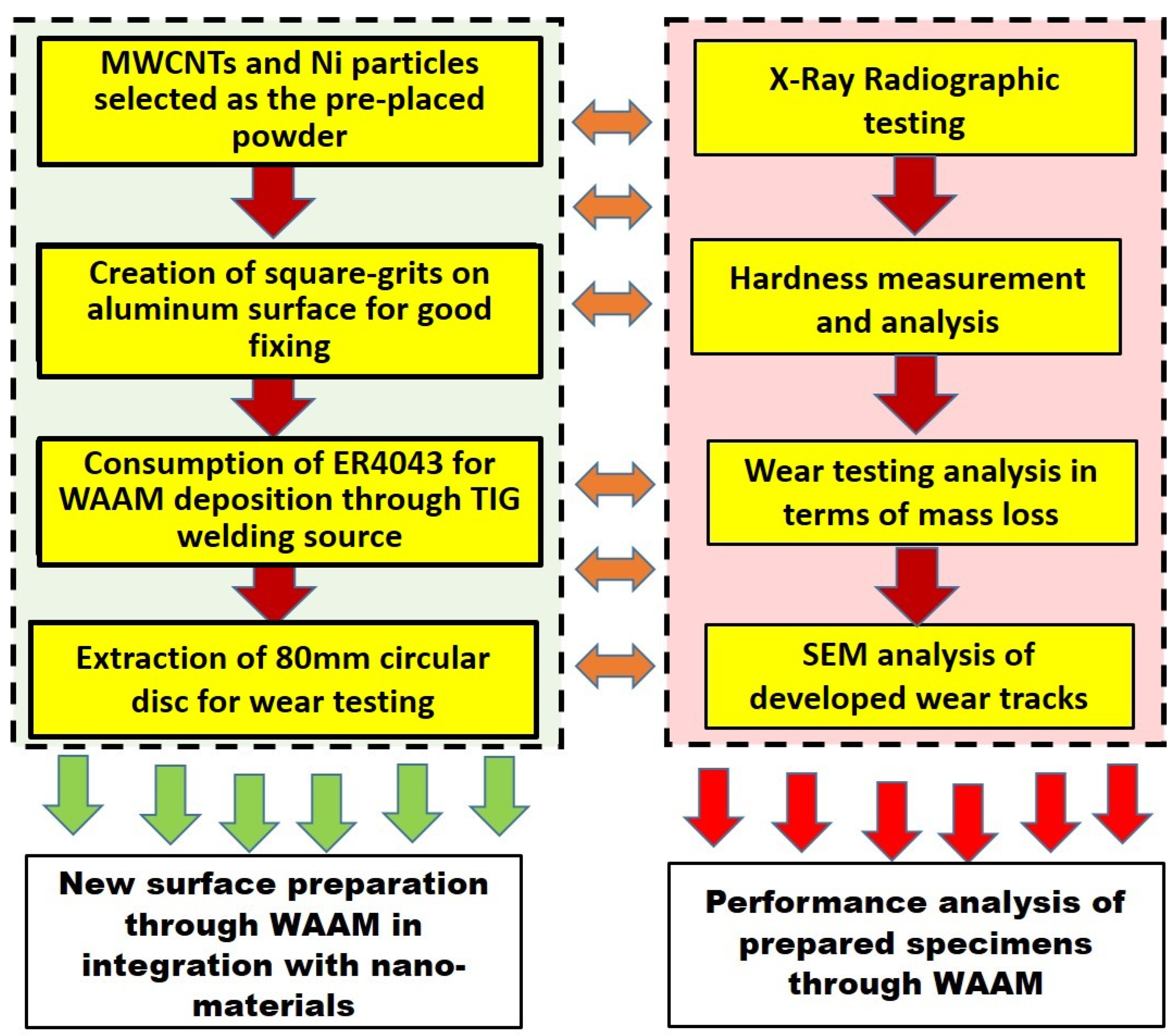
2. Experimental Procedure and Methodology

The experimental procedures consisted of two stages, which are graphically illustrated in the roadmap of the overall work in Figure 1. The first stage is the preparation of new surfaces through WAAM integrated with the addition of nanomaterials, which includes the sequence of operation as highlighted in Figure 1 and described in Section 2.1, while the second stage involves the performance analysis of prepared samples, including radiographic testing, hardness measurements, and dry sliding wear behavior characterization.

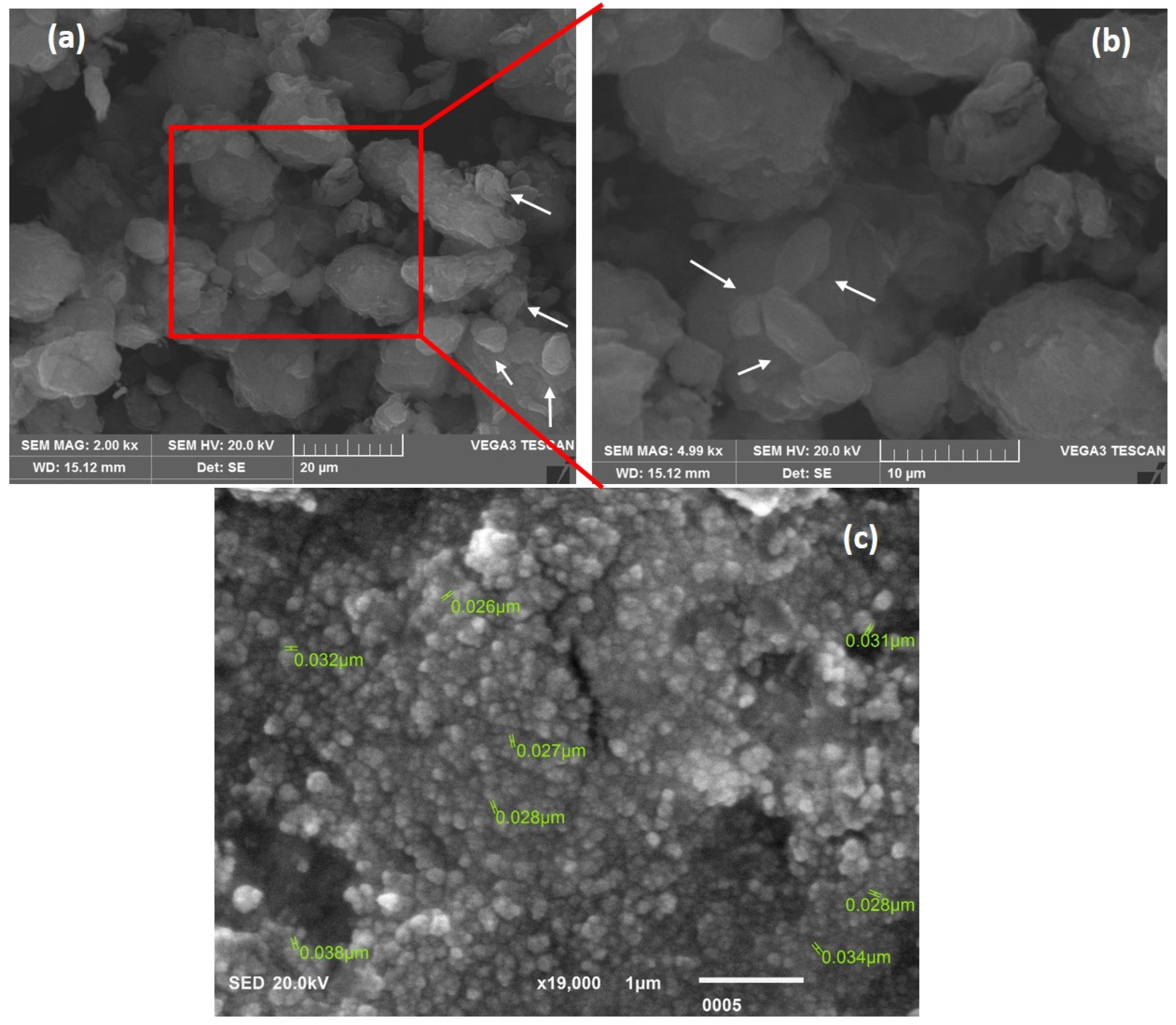
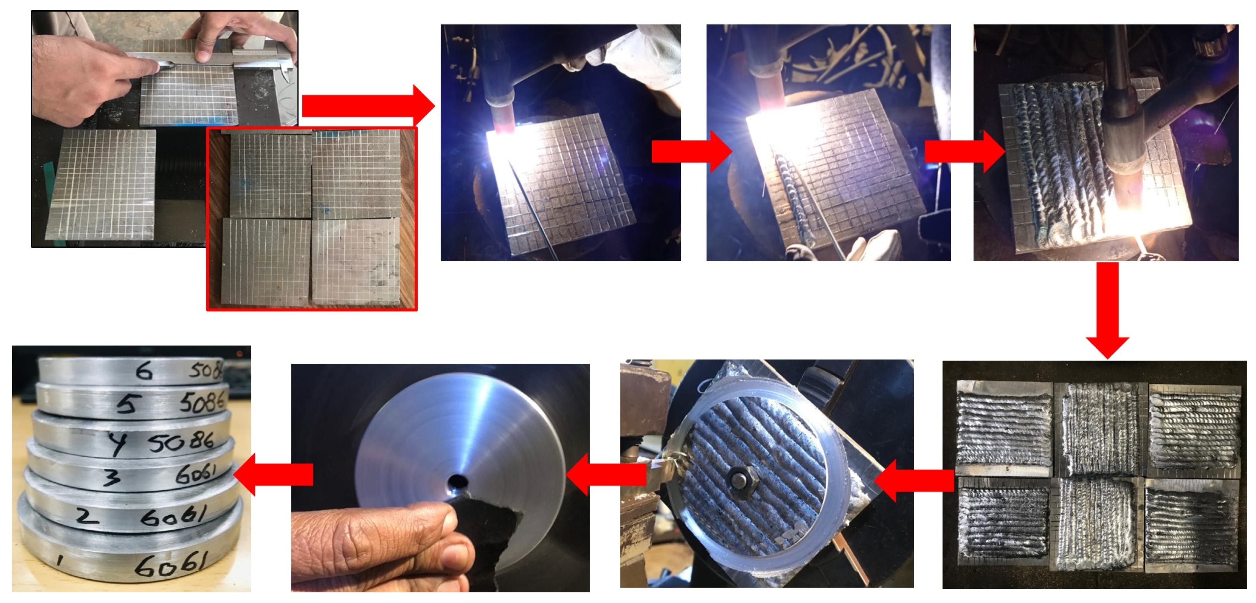
2.1. Materials and WAAM Procedure for Samples

Commercially available aluminum alloy plates of 8 mm thickness of AA6061 and AA5086 were utilized with a standardized composition and were later cut into square pieces of dimensions 110 mm × 110 mm in rough compliance with the wear-testing machine. Carboxyl-functionalized MWCNTs, with a mean length of 30 μm [31] with some available fine tubes of about 5 µm in length (highlighted with white arrows) and a Ni particle size of 70–90 nm, purchased from PR China were utilized in the study as the pre-placed powder coating before the WAAM. For coating, two solutions were prepared in a bottle of 20 mL ethanol that contained 0.01 and 0.02 g of MWCNTs and 0.2 g of Ni particles in the solution. Figure 2a–c highlights the as-received morphologies of MWCNTs and Ni particles.
The dispersion of the solution was performed through the creation of 5 mm square grits on the surfaces of aluminum alloys, where the straight lines were scribed with 5 mm differences and a slight, deep impression for good fixing of particles during the period of pasting and during filler deposition. The prepared solution was applied to this prepared grit on the aluminum substrate surface and dried for about 40 min. Ethanol evaporates quickly and leaves a uniform coating on the surface.
ER4043 was consumed as the filler material for additive deposition using a TIG welding machine with a non-consumable tungsten electrode. The WAAM deposition was executed through a manual feeding torch operated on alternating current consuming pure argon as a shielding gas with a flow rate of 18 L/min. A 3.2 mm tungsten electrode was used in the torch at 180 A of welding current, which remained constant for all the samples. The pictorial sequential representation of the surface preparation and wire-arc deposition is given in Figure 3. All the samples were prepared using a single-pass wire-arc additive deposition. The samples were prepared according to the experimental scheme given in Table 1. After WAAM, 80 mm discs need to be prepared with a center bore of 8 mm diameter on each sample by drilling to fix them in the fixture of the wear-testing machine. A series of machining operations are required to finalize the 80 mm disc samples from the previous dimensions and to create an even surface along with the application of 800# grit size SiC abrasive papers on the surface, as also highlighted in Figure 3.

2.2. Sequential Methodology to Assess WAAM Surface Performance and Characterization

The WAAM-prepared surfaces were subjected to various performance tests and characterizations to evaluate the changes in wear behavior. The work started with radiographic testing (RT), which was used to detect cracks and voids in the deposited interiors over the base metal and any discontinuities in the prepared samples. Further, a Rockwell digital hardness tester was used to analyze the variation in the performance of hardness with the addition of MWCNTs and Ni particles. Scale B was set while a steel ball indenter with a diameter of 1/16 inch and 980.7 N test force was used to measure all the readings. All the readings were taken at the top, newly developed surfaces through WAAM with a step size of 5 mm.
In addition, the wear-testing is the critical and most important step of this presented work. It assesses the actual mass loss comparison after the inducements of MWCNTs and Ni particles in the AA6061 and AA5086 alloy. Therefore, wear testing was carried out on all three samples of AA6061 and AA5086 including without, with high, and with low contents of MWCNTs as prescribed in Table 1. For this, a laboratory procedure is used to find the mass loss during the dry sliding wear. ASTM G99-05 [32] standardized guidelines for wear testing on pin-on-disc apparatus were followed where a pin is positioned perpendicularly with a flat circular disc. Either the pin or disc can be treated as an observable sample, which may cause rotation for the creation of circular tracks. For this work, a tungsten carbide pin was used as a superior material stationary pin with the flat revolving discs prepared through WAAM and subjected to the measurement of mass losses.
The further guidelines from the ASTM G-99-05 wear-testing standard involved speed (revolutions per minute, RPM), load, and sliding distance, which could be the variable parameters, while temperature and atmospheric conditions may also be accounted for. In this study, the rotating time and radius of the sample disc were set to achieve the desired sliding distances, and the rotating speed and load were the constant parameters. To achieve this, the prepared WAAM sample discs were placed in the provided disc holder, and the desired radius between the tip of the pin and the center of the disc was adjusted via a base slider to the disc holder in the machine. Secondly, after placing the disc properly, the speed controller was triggered to rotate the disc at a constant speed of 620 RPM up to the desired time duration, which was monitored with the aid of a tachometer and a stopwatch.
The prepared WAAM disc samples were tested for dry sliding wear by using an in-house developed wear-testing machine, formally called the pin-on-disc machine, as shown in Figure 4. As highlighted and shown in Figure 4a, the machine used for testing is equipped with a dead load, sliding pin, motor, and speed controller, while in Figure 4b, a rotating disc-holder is shown that carries the under-observation disc sample and is tightened with the Allen key from the center bore. The tests were conducted at room temperature. The circular disc samples of AA6061 and AA5086 of 80 mm in diameter were used for studying the mass loss from the developed WAAM samples. Two sliding distances were selected (i.e., 500 m and 600 m) to observe the wear behavior for both alloys. To avoid any variation during the manufacturing process, both sliding distances were used for the same sample by considering two different radii on the discs for two readings for each sliding distance. The details of the executing parameters include the following: a 1 kg normal dead load along with four radii values (i.e., 17 mm, 25 mm, 30 mm, and 37 mm) to achieve 500 m and 600 m sliding distances in their respective times. Before and after each execution of wear testing, the electronic mass-balance device with a sensitivity of three digits was used to measure the wear loss. The SEM was used to visualize the developed wear track morphologies after the pin-on-disc testing. The wear track appearances were recorded in terms of the mechanism of wear with the sliding of the pin, while the other available features at the wear track surface were also captured and analyzed through the obtained SEM images.

3. Results and Discussion

The Results and Discussion section comprises three important subsections after the radiography test, namely, the hardness, mass loss, and the wear track analysis, to elucidate the wear mechanism through SEM images resulting in the inducement of nanomaterials through WAAM surface development.

3.1. Radiographic Resting Results

Radiographic testing is a valuable aspect in providing critical insight into the structural integrity and the assessment of quality of the prepared new surfaces through WAAM with the benefit of non-destructive evaluation. X-rays have limitations that make it more challenging to detect the defects and assess the quality of the deposited layers. These include the high X-ray absorption, thick or dense deposition of material layers, and inspecting the complex geometries with intricate shapes, which result in poor image contrast, improper penetration of X-rays, and uneven attenuation leading to image distortion and false artifacts. The primary concern for the utilization of radiographic testing after WAAM is to spot internal defects, including porous regions, cracks, and inclusions. The absence of all the stated defects is a key indicator of multiple aspects, including the control over the process of WAAM, good fusion, and consistent deposition of successive layers throughout the samples.
In the context of this presented work, the radiographic testing was conducted on both the selected alloys, AA5086 and AA6061, with the principal focus of understanding the inclusion of MWCNTs and Ni nanoparticles along with successive addition of filler material through WAAM. For this, radiographic testing and analysis of the fabricated surfaces were conducted, and the recorded film images are presented in Figure 5a–e. Figure 5a–c depicts the X-ray radiographs of sample discs of AA6061, which were deposited with only a weld layer of an electrode (without nanoparticles), with 0.02 g and 0.01 g of MWCNTs along with constant Ni contents. Similarly, Figure 5d,e depicts the X-ray radiographs of sample discs of AA5086, which were deposited with a layer of the electrodes (without nanoparticles) with the deposition of 0.02 g of MWCNTs.
The obtained radiographic film presented in Figure 5a–e serves as the fundamental element in the comprehensive assessment of the quality of deposition through WAAM. The films obtained for AA60061 in Figure 5a–c and AA5086 in Figure 5d,e offer a window into the interior of the samples to compile the findings related to the absence or presence of significantly large porous regions and pores. This is highly effective as it directly reflects the quality of WAAM along with the inclusion of nanoparticles. It is evident from Figure 5a–e that there are no substantial flaws (e.g., cracks) in the additively deposited metal, not even at the interface zones between the deposited layers and the substrate in any of the samples for both the alloys. Additionally, an X-ray radiographic scan of samples with and without nanoparticles revealed no significant porous regions or incorrect fusions between the successive layers. Even the color contrast of the images did not indicate any significantly darker areas, which highlights significant discontinuities, nor does it show any light-deposited, high-density regions.
Furthermore, the finding of the above-stated defects is crucial in establishing a basis of comparison to assess the differences with and without inducements of nanoparticles along with WAAM, as any deficiency leads to less integrity and creates negative effects on the wear behavior. The absence of any substantial defects is evident from Figure 5, which shows enhanced integrity and reduced susceptibility to stress concentration for further sliding action from wear testing. The incorporation of MWCNTs and Ni particles can safely strengthen the material and improve hardness and wear behavior. Ultimately, these findings demonstrate that the TIG-based heat sources have been able to produce good, high-density layer bonding along with no serious flaws.

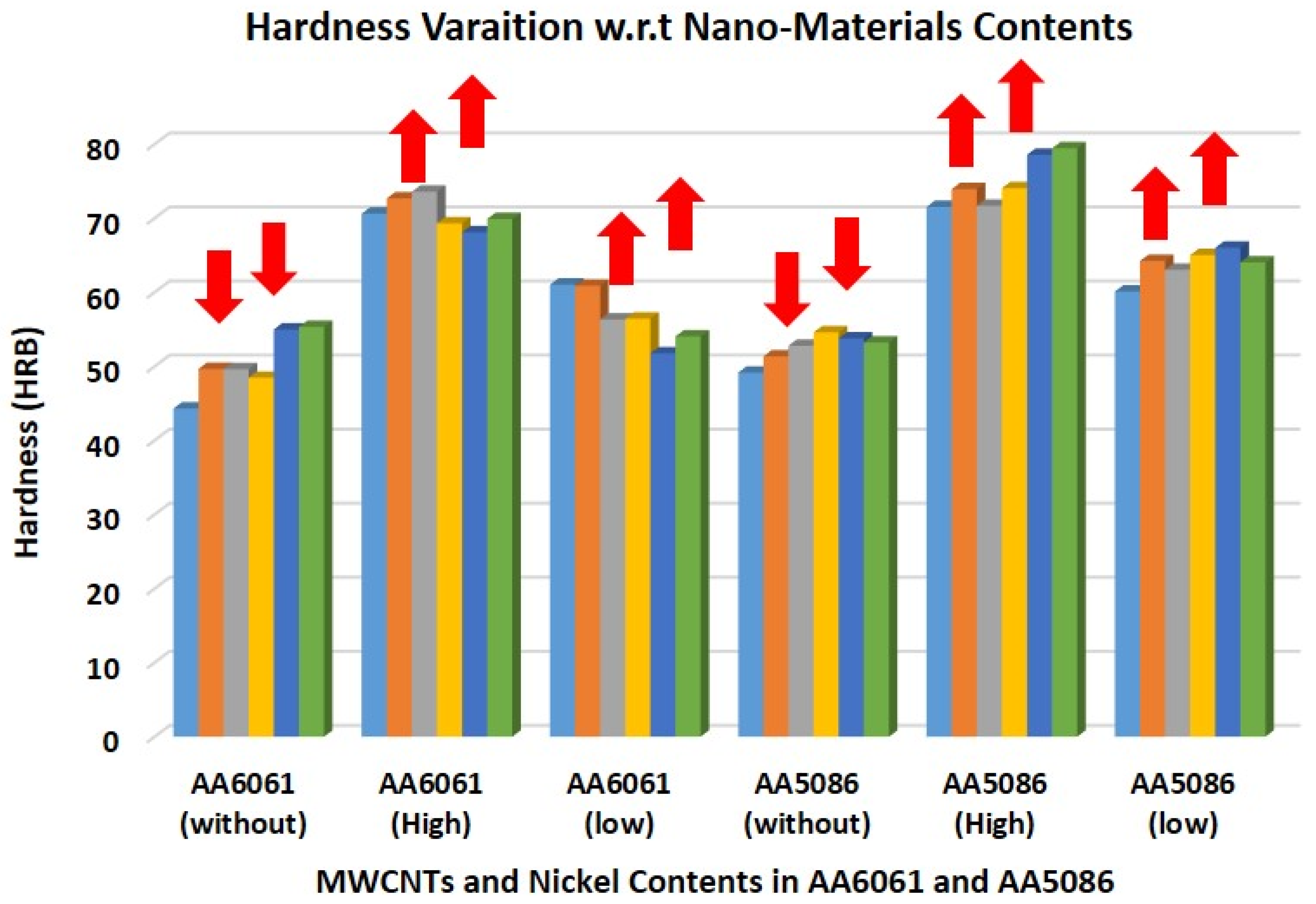
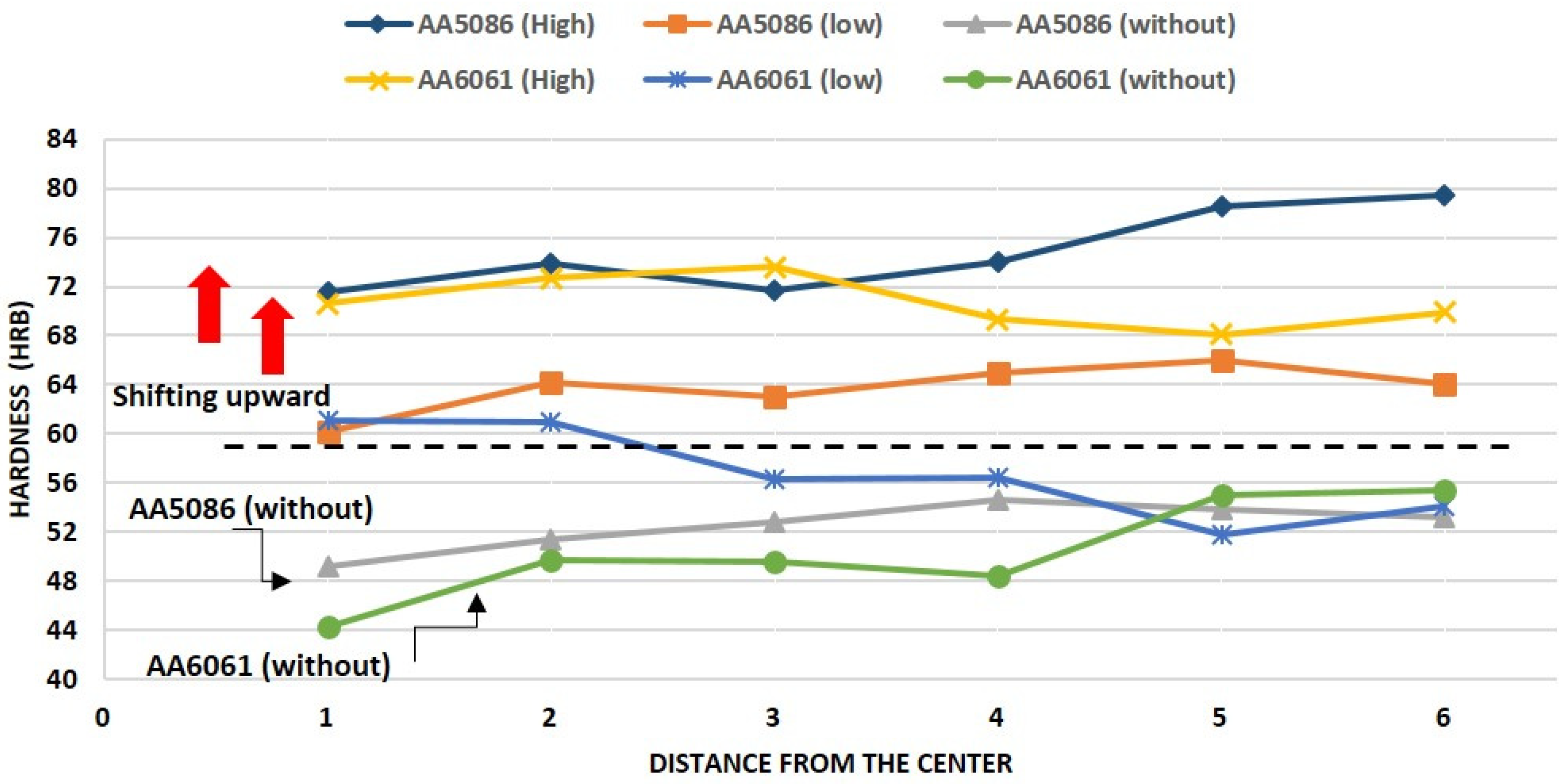
3.2. Microhardness Test Results

The hardness of the samples prepared additively for characterization was recorded and analyzed. The HRB (Rockwell B) is the commonly used method to assess the hardness of non-ferrous alloys. The process of measurement involves a similar technique of applying a minor load first to ensure the proper contact and subsequently a major load causing the indenter to penetrate the surface. Figure 6 shows the obtained hardness values (HRB) of all the six WAAM samples graphically. In Figure 6, the first block highlights without any inducement, while the second and third block shows the high and low contents of MWCNTs, respectively, in AA6061 alloy. The same sequence of representation is followed for AA5086 in Figure 6.
Figure 6 shows the variation in the individual obtained values of the hardness of additively prepared WAAM samples. The samples at the initial three blocks in Figure 6 depict the without, high, and low contents of MWCNTs inducements at AA6061. The first block shows the lowest average value of hardness, i.e., 50.39 HRB, while the second block, which is the case of high contents of MWCNTs in AA6061, showed a rapid increase in the hardness (highlighted with red arrows) and an average of hardness equivalent to 70.76 HRB. The sample at the third block of AA6061 of low contents of MWCNTs depicts a decrease compared to the second block but an improvement in the average hardness value when compared to the first block. In addition, the next three blocks belong to AA5086 under the without, high, and low content conditions of MWCNTs. Similarly, the block of high contents of MWCNTs along with Ni showed a rapid increase in the average hardness value by giving a value of 74.86 HRB. The sample block of low MWCNTs showed a gradual decrease in the hardness by giving the value of 63.74 HRB. However, the case without any inducement highlights the low average value of hardness (highlighted with red arrows), 52.48 HRB, in comparison with the blocks of high and low contents of MWCNTs as given in Figure 6.
It is observed and concluded that AA6061 and AA5086 with higher contents of MWCNTs show the highest hardness values, although the effect of low contents of MWCNTs also improved hardness properties in contrast to without inducement condition. This happened because MWCNTs and Ni are both responsible for affecting the hardness in a positive direction. The introduction of MWCNTs further elevates the properties of the developed matrix by seamlessly intertwining with an intricate network of compounds or also supporting the formation of carbide Al4C3 [33]. This development engenders a robust barrier in the dislocation movement and offers high resistance to plastic deformation, which consequently augments hardness values. Moreover, Ni improves the toughness and strength through a strong affinity towards aluminum for the formation of inherited intermetallic compounds that are characterized by exceptional mechanical attributes [34,35].
Figure 7 shows the variation in hardness of AA6061 and AA5086 concerning distance from the weld center for the high and low contents of MWCNTs, and the without inducement cases for both the alloys. From the observed trend, the highest values of hardness (HRB) were observed in the samples that were prepared and deposited with high contents of MWCNTs, while Ni content is the same in both cases. There is a series of increases and decreases in the hardness values for all six samples at the measurement points. For the case of AA6061 and AA5086 deposited layers without nanoparticle inducements, there was static behavior or very limited increase in hardness in every succession moving away from the center due to the generic exposure to heat from the torch. If an imaginary line is plotted, Figure 7 is divided into two portions, one above and one below 60 HRB; the values of hardness for without inducement cases of AA6061 and AA5086 are found at the lower portion that highlights the low hardness of deposited layers. The low contents of MWCNTs in AA6061 and AA5086 are found in the upper portion of Figure 7. Similarly, the higher inducements of MWCNTs further advance significantly towards this same portion (indicated with red arrows) as considerable hardness measurement points fall in this upper region. Both MWCNTs and Ni particles are responsible for hardness improvement and the transformation of these hardness profiles depicted in Figure 7.

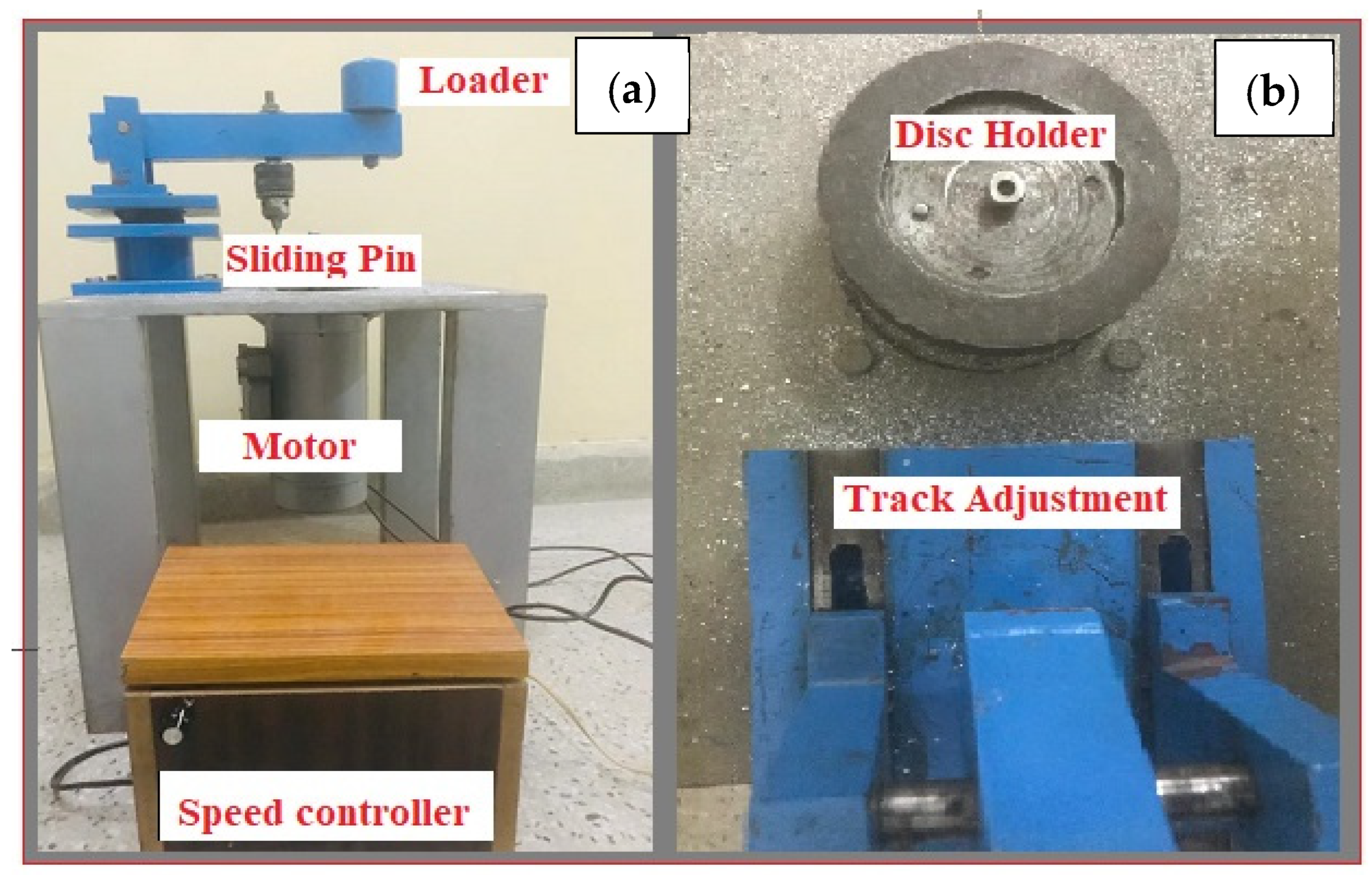
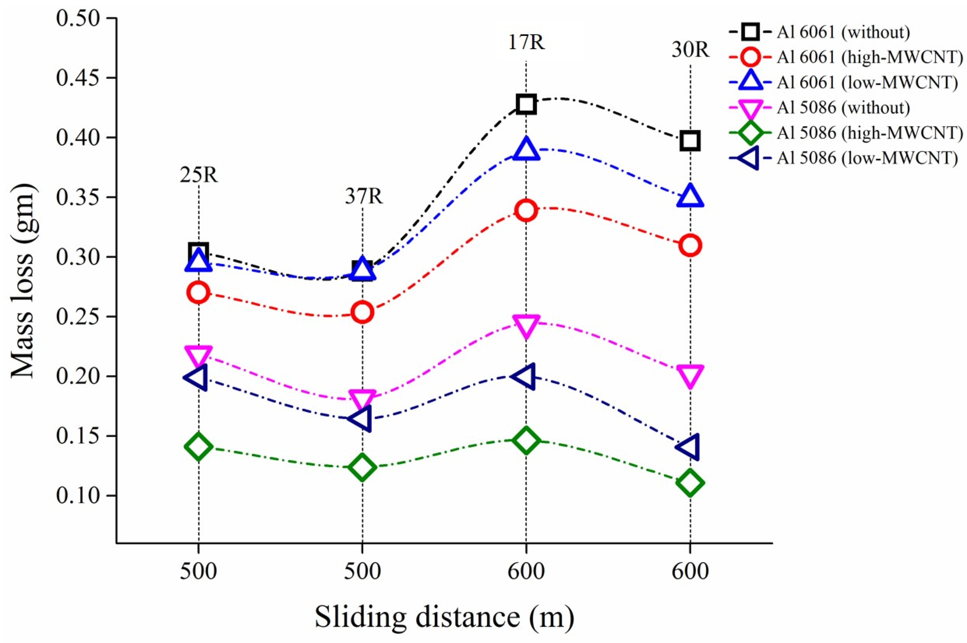
3.3. Wear Test Results

The pin-on-disc test machine was used to assess the wear behavior in dry sliding conditions. Circular discs of 80 mm in diameter of AA6061 and AA5086 were used. They were additively deposited with the layer of the electrode along with MWCNTs and Ni particles. Two sliding distances (500 m and 600 m) were selected for this study to assess the wear resistance behavior and performance. To execute the wear testing, four radii were considered (17, 25, 30, and 37 mm) on circular disc samples to ensure the 500 m and 600 m sliding distances were covered at their respective times. This strategy was adopted to avoid any variation by not considering another disc for the same case of the experimental run. Therefore, 25 mm and 37 mm radii were selected as the two readings for 500 m and 17 mm and 30 mm for 600 m sliding distances. So, ultimately, wear testing in terms of mass losses was performed four times on each additively prepared disc, two times for 500 m and 600 m sliding distances with the above-considered radii, and the results are displayed on an individual basis in Figure 8.
The graph given in Figure 8, shows the relation between sliding distances and the mass loss of each sample of AA6061 and AA5086 with and without nanoparticles addition. Here, the individual mass losses of 500 m and 600 m sliding distances that were tested twice on different radii are presented. It was observed from Figure 8 that the same sliding distance may lead to slightly different results for different track radii. This graph indicates that the higher mass losses at both the sliding distances belong to the without inducement cases for AA6061 and AA5086 alloys. However, the graph gradually moves down in the vertical direction as the mass contents of MWCNTs increase from 0.01 to 0.02 g for both the considered alloys. The mass loss for AA6061 remains consistently higher in contrast with the AA5086 for the addition of 0.01 and 0.02 g of MWCNTs. Eventually, the graph settles at the bottom for the lowest mass loss condition at 0.02 g (high) inducement in AA5086. A noticeable situation is a considerable increase in the mass loss between the 500 m and 600 m sliding distances at a low level of inducements (i.e., 0.01 g of MWCNTs), while a slightly similar mass loss with a low slope is observed at the high level of inducements, i.e., 0.02 g of MWCNTs.
The total obtained values of mass loss for 500 m and 600 m sliding distances for all six samples are presented in Table 2. The mass losses of the samples without any inducement of nanoparticles along with WAAM are higher than those of the samples with MWCNTs and Ni inducements, possibly because of the dissolution of the precipitates that were available in the initial stages, which further reduces the hardness and in turn increases the mass loss upon the application of heat. The table shows that samples 1 and 4, which were only prepared with ER4043 electrodes with WAAM, exhibited higher mass losses and thus showed low wear resistance in comparison with the other samples. It can also be concluded that a total mass loss of 1.32 and 1.17 g was recorded for AA6061 at low and high contents of MWCNTs along with Ni particles, showing enhanced resistance in comparison with sample 1. In addition, the graph shows the lowest mass loss and the highest resistance of wear for sample 5 in comparison to all the samples prepared from WAAM cases for AA6061 and the cases of without and 0.01 g of MWCNTs (i.e., samples 4 and 6). So, it can be concluded from the total obtained values depicted in Table 2 that the higher contents of MWCNTs and Ni particulates significantly reduce the mass loss and enhance the wear resistance.
Apart from the individual and average values, the improvement in the mass loss percentages in terms of resistance offered by the addition of MWCNTs and Ni is also an important consideration. Most prominently, the resistance is improved up to 38.46% for AA5086 and 17.31% for AA6061 with the high contents (0.02 g) of MWCNTs in comparison to the cases of their respective samples without inducements, i.e., samples 1 and 4. This percentage improvement is supported by the formation of hard nickel aluminates [14,18,34,35] and aluminum carbides [33,36] in the matrix, which increased the wear resistance.

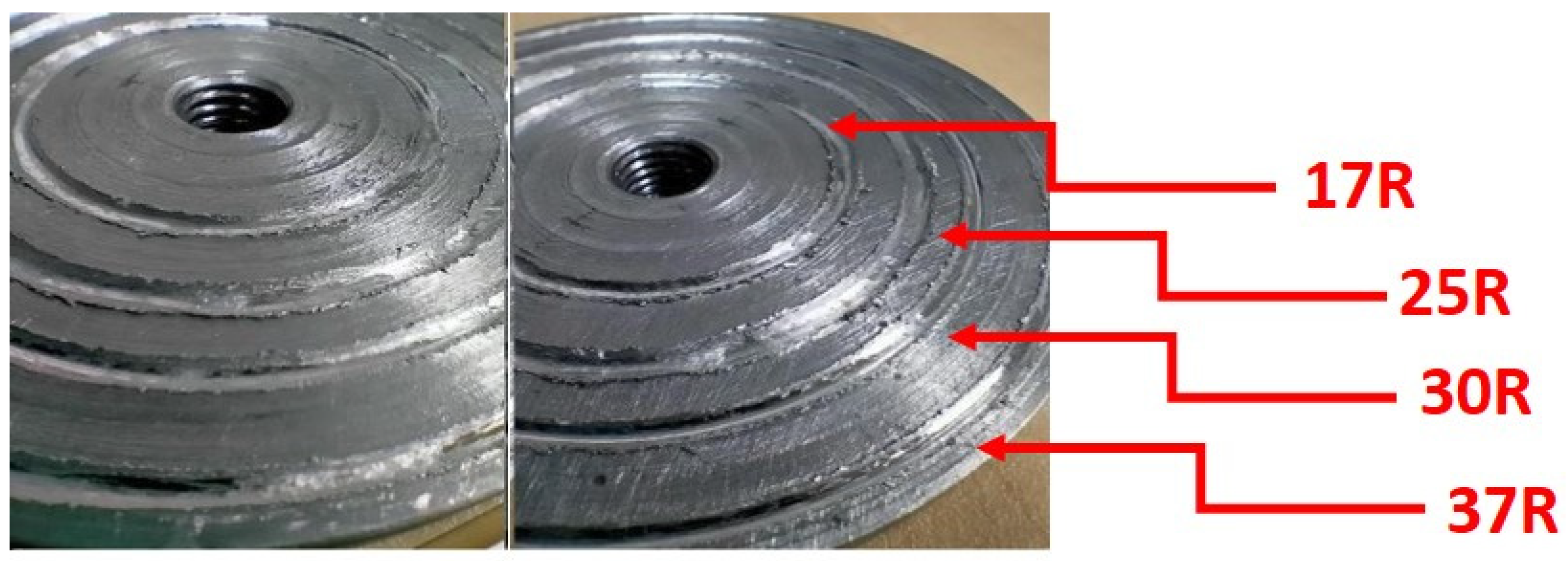
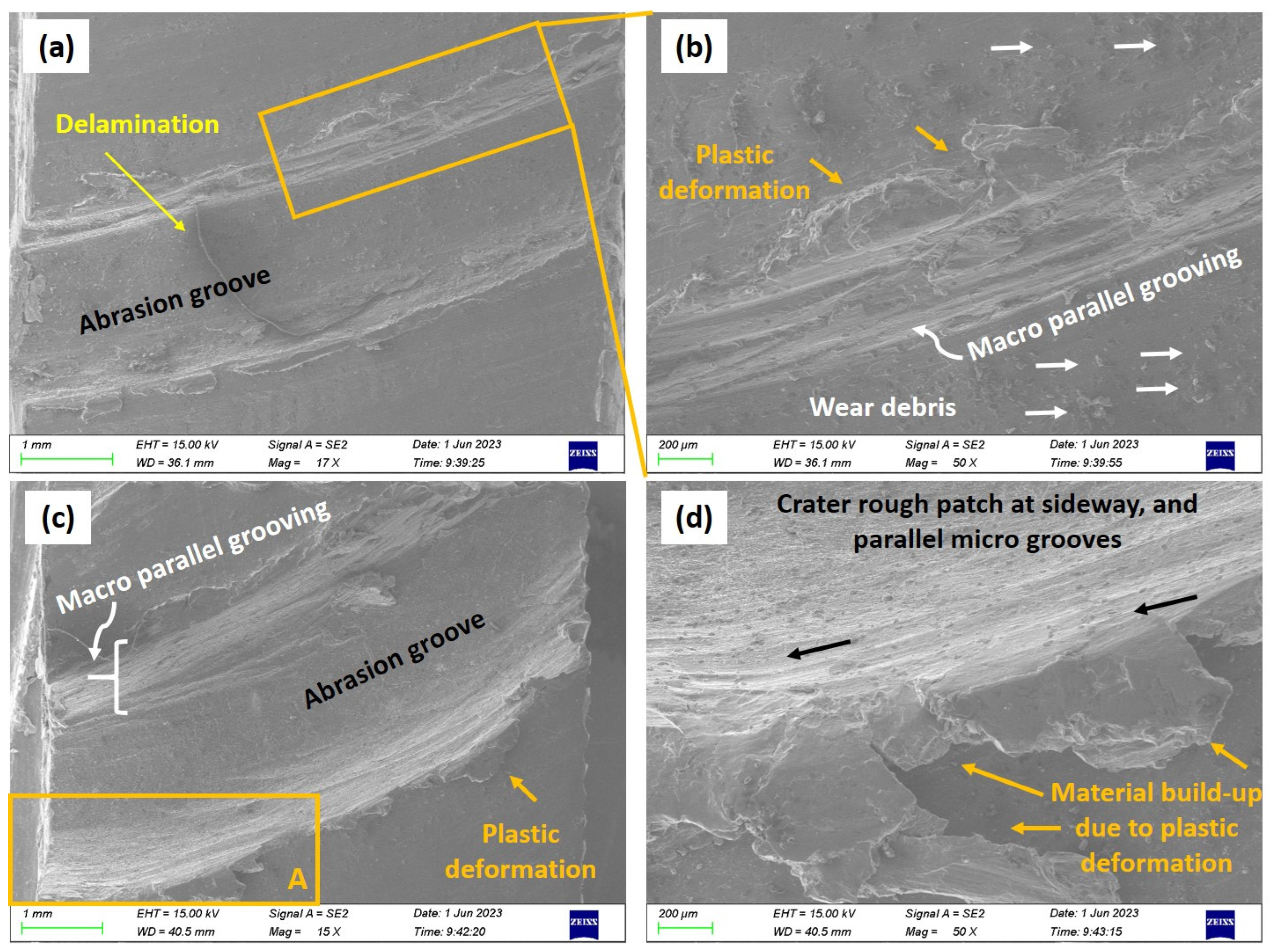
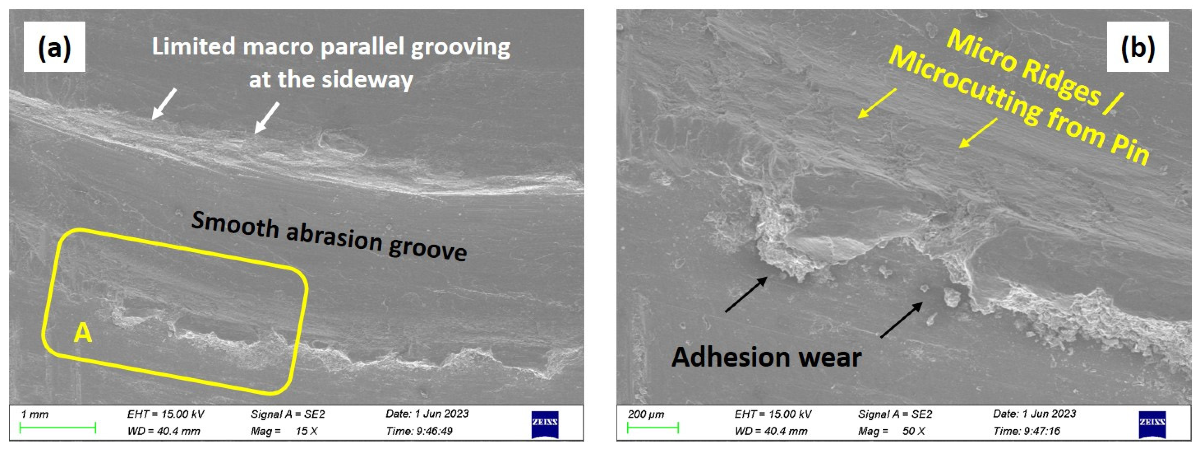
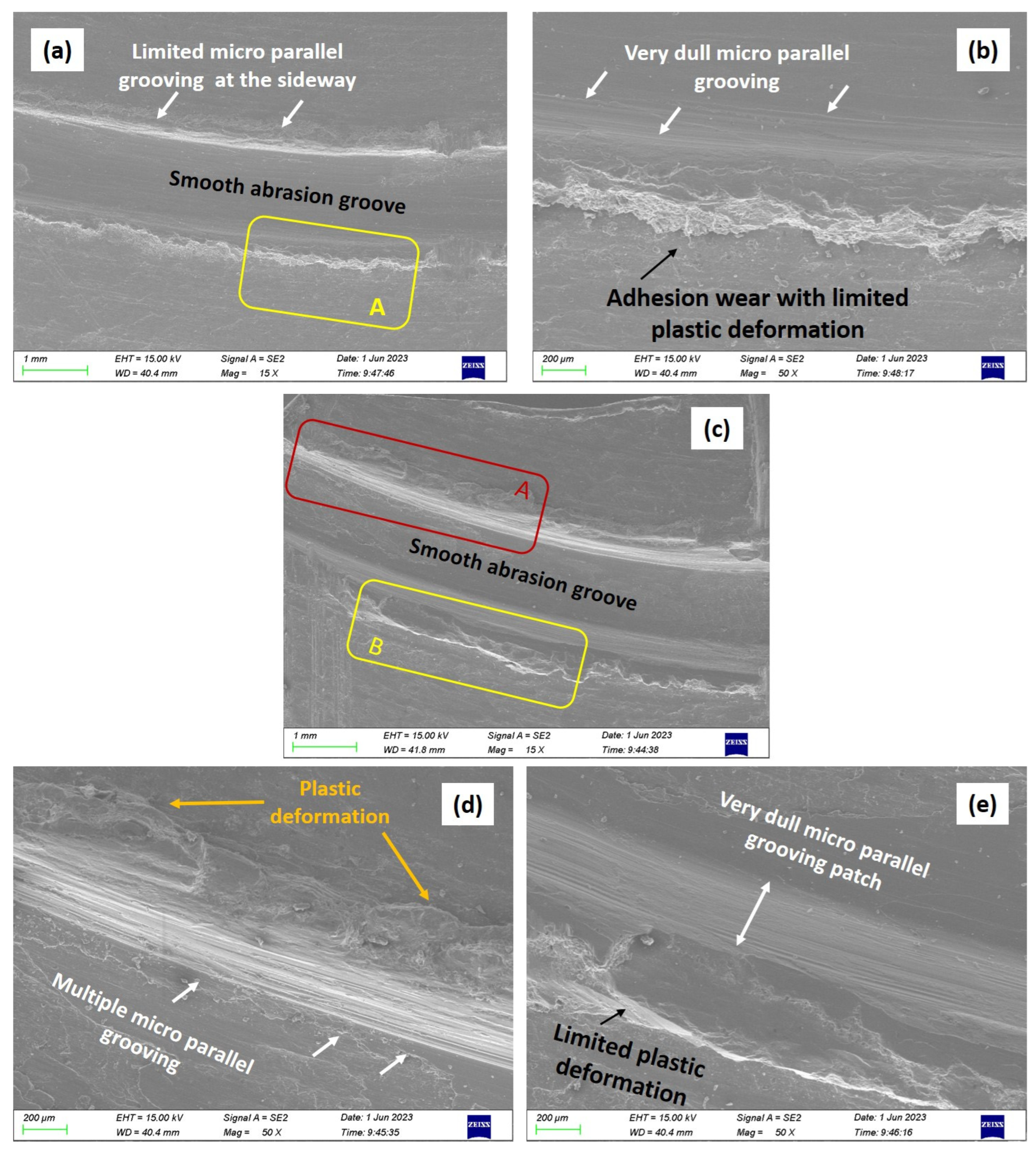
3.4. Wear Image Analysis of Typical Wear Tracks on Discs

Figure 9 shows the sequence of the wear track images on the newly developed WAAM surfaces, which indicate the streaked wear tracks that are difficult to explain visually in terms of mechanism from these macro-images. All four wear tracks on the single samples are clearly evident for the 17 mm, 25 mm, 30 mm, and 37 mm radii. A comparative scheme was developed to illustrate the sliding wear behavior with and without inducements of nanomaterials with the aid of SEM images, which are discussed in detail individually. Figure 10 shows the macro-cross-section images after the wear track developments from all four radii without inducement in AA6061 and with 0.02 g of MWCNTs in AA5086. As depicted in Figure 10a,b, the samples revealed deep grooves for all the radii for the without inducement case of AA6061, and, for comparison, the cross-section grooves are provided in Figure 10c,d for the case of 0.02 g of MWCNTs in AA5086 alloy. The deep tunnels are observable at the section for all four radii in Figure 10a,b; however, a specific one is marked and highlighted in Figure 10b for the 17 mm radius. As highlighted in Figure 10c,d, less severe deformation of the grooves and tunnels is visible with the addition of 0.02 g of MWCNTs. In contrast with the case in Figure 10a,b, well-confined fine and shallow furrows at the cross-section are visible for all four radii in Figure 10c,d, which is the case of 0.02 g of MWCNTs along with Ni particles in AA5086.
Figure 11 shows the SEM images of wear tracks developed for AA6061 aluminum alloy at 500 m sliding distance without any inducement of MWCNTs and Ni particles during the WAAM technique as a DED. Figure 11a,b show the wear track images at the 37 mm radius, while Figure 11c,d depict the track developed with the 25 mm radius. The details of the features encircled in Section A in Figure 11a,c are magnified in the subsequent SEM images in Figure 11b,d, respectively. The obtained SEM images reveal that adhesive wear is the predominant wear mechanism for both the radii of 500 m sliding distances. The static pin interacted with the newly developed surfaces at repeated times, initiating the generation of an abrasion groove at the center along the major axis of sliding direction as given in Figure 11. As a consequence, multiple features were developed at the center and along the side of Figure 11, including material buildup due to plastic deformation, abrasion groove width, wear debris, and micro- and macro-parallel grooving. The large amount of plastic deformation is categorically visible and highlighted in Figure 11c at both the side of the 25 mm radius in comparison to the wear track of the 37 mm radius. The enclosed Section A given in Figure 11c is magnified in Figure 11d, where the large amount of adhered buildup material at the side confirms the plastic deformation due to adhesion wear [37]. The adhesion wear is also the prevalent wear mechanism for the case of the 37 mm radius, but the creation of higher contact stresses [38] at the nearer radius (i.e., 25 mm) demonstrated more visible features of plastic deformation as depicted in Figure 11d in contrast to Figure 11b. Based on this, a wider abrasion groove is observed for the 25 mm radius in Figure 11c than the groove for the 37 mm radius given in Figure 11a. Moreover, for a similar reason, the sideways examination of grooves revealed more extended patches of micro-parallel grooving in Figure 11d and confined patches of macro-parallel grooves in Figure 11a,b. Apart from that, very limited traces of abrasive wear were observed in terms of wear debris inside the boundary of track as given only in Figure 11b of the 37 mm radius. A radial hump also developed at the extreme edge of the longest wear track (i.e., 37 mm) of the system considering the repeated number of cycles in executing the wear testing as shown in Figure 11b.
The wear track attributes of the 600 m sliding distance at 30 mm and 17 mm radii with the same wear-testing conditions of WAAM samples are presented in Figure 12a–d. The SEM images shown in Figure 12a,c depict the extended widths of abrasion grooves for both tracks. A deep furrow is exhibited for the 30 mm wear track along with an appreciable sign of plastic deformation as given in Figure 12a, while an extremely deep and wide furrow developed for the case of the 17 mm wear track given in Figure 12c, even more severe in comparison with the previous case of 500 m sliding distance. Again, the exposed morphologies captured in SEM images given in Figure 12 are related to the adhesive wear, with a larger amount of plastic deformation than the 500 m sliding distance. Moreover, the detailed features of the sideways wear tracks (30 mm and 17 mm) are magnified in Figure 12b and Figure 12d, respectively. The sideways examination of the 30 mm radius track revealed multiple macro-parallel grooves, specifically at the upper side, in contrast to the lower side of the track as highlighted in Figure 12b. The reason was a repeated number of cycles where the sliding pin penetrated more toward the inside upper side and created sequential parallel grooves [39]. Therefore, the existence of macro-parallel grooves on the upper side of the 17 mm track is also visibly evident and highlighted in Figure 12c. In addition, a case of higher contact stresses developed at the 17 mm wear track, where more frictional heat is induced because of two reasons: the smallest radius of the track (i.e., 17 mm) and higher sliding distance (i.e., 600 m). Based on this, Section A, highlighted in Figure 12d, categorically showed the lumps of buildup material caused by extreme plastic deformation, where material is pulled or squeezed out from the boundary of the track. Similarly, a lump of deformed material also developed at the edge of the 30 mm track given in Figure 12b but not as severe as that obtained for the case in Figure 12d. Moreover, the morphology at the edge of the track shows a pronounced effect of the pin more towards the inside of the track in terms of crater rough patch creation along with the macro-parallel groove signs.
Figure 13 shows SEM images of the worn surface of the developed wear track with the high mass contents (0.02 g) of MWCNTs in the AA5086 matrix. Before highlighting the wear mechanism, cases without and with the inducement of MWCNTs revealed an abrasion groove in the center but of different morphologies. The wear groove presented for the case of high mass content of MWCNTs for a sliding distance of 500 m in Figure 13a is not too deep and wide open from the sides, and shows that the track is consistent and confined in terms of dimensional stability in contrast to the previous cases given in Figure 11 and Figure 12. A very smooth abrasion groove is highlighted in Figure 13a; the samples addressed the situation of wear involving the sliding of the pin with the development of a strong matrix through the addition of MWCNTs and Ni particles. This situation is more helpful in arresting the flow of material through MWCNTs addition, which is also evident from the side features highlighted in Figure 13a,b. The examination revealed a limited patch of macro-parallel grooves at the upper side, while the slight signs of micro-ridges at the bottom side [40] are highlighted in Section A of Figure 13a and magnified in Figure 13b. The ridges are concentrated at the side boundary of the track with low amplitude, which is a sign of offering more resistance to plastic deformation.
The effect of high MWCNTs on the 600 m sliding distance and the developed wear tracks with 30 mm and 17 mm radii is given in Figure 14. The characteristics of the developed abrasion grooves with 600 m sliding distance, given in Figure 14a,c, are quite similar to the previous case of 500 m sliding distance given in Figure 13. The condition of the developed tracks with 0.02 g (high contents) of MWCNTs is not severe as obtained for the without inducement case of MWCNTs with the same radii of tracks (i.e., 30 mm and 17 mm) presented with the aid of SEM images in Figure 12. Again, the abrasion grooves of high mass contents of MWCNTs are not too deep and wide open from the sides, and show consistency and confinement in terms of dimensional stability of the tracks given in Figure 14a,c even at 600 m sliding distances. However, a smoother abrasion groove and dimensionally controlled wear track were obtained for the case of the 30 mm radius, and a slightly more plastically deformed wear track was obtained for the 17 mm track because higher frictional heat induces the creation of higher contact stresses at the smallest radius of the system. Furthermore, the obtained patterns of tracks in Figure 14 indicated that adhesive wear is the prevalent wear mechanism for the inducement of MWCNTs in the matrix but with limited features of plastic deformation. Similarly, as the counter sliding pin interacts with the surface developed with the inducements of MWCNTs and Ni nanoparticles, multiple visible fissures and features are developed at both the sides. A very limited patch of micro-parallel grooving is present at the upper side of the track as highlighted in Figure 14a, much smaller and limited to the case presented in Figure 12b, which is the case without any inducement of MWCNTs. The enclosed Section A (bottom side) in Figure 14a is magnified in Figure 14b, where a very minute amount of adhered buildup material is present along with extremely dull marks of micro-parallel grooving because of the high-strength matrix developed from MWCNTs inducement. A considerably improved wear track with high contents of MWCNTs in terms of dimensional stability, adhered buildup materials, and micro/macro-groove patches at the 17 mm radius is presented in Figure 14c in contrast to the previous case given in Figure 12c,d against the same sliding distance of 600 m. A slightly smoother abrasion groove is highlighted at the center in Figure 14c, and the upper (Section A) and lower sides (Section B) are magnified in Figure 14d,e. The upper side examination in Figure 14d revealed the limited signs of plastic deformation and multiple micro-parallel groove patches up to a certain width, as this is a case of higher contact stress generation at the nearest radius (i.e., 17 mm) and a larger sliding distance (i.e., 600 m), similar to a case highlighted in Figure 12 for without any inducement of MWCNTs. While limited signs of plastic deformation and the very dull patch of micro-parallel grooving are exhibited at the bottom side of the track given in Figure 14e because of a similar reason of the high content of MWCNTs in the matrix of AA5086 alloy.

4. Conclusions

A new surface development was executed with WAAM on AA6061 and AA5086 alloys along with two different mass contents of MWCNTs and fixed mass content of Ni nanoparticles and was further studied for wear assessment in terms of mass loss. The following conclusions are drawn from the obtained findings and results:
The higher mass contents, 0.02 g of MWCNTs, showed the highest hardness values of the systems for AA6061 and AA5086 alloys in contrast to low mass contents and without any inducement. The maximum value of 74.86 HRB was achieved at a 0.02 g inducement of MWCNTs for AA5086 alloy.
In wear testing, the higher values of mass losses were recorded for the cases of WAAM of AA6061 and AA5086 alloys without any inducements at both the sliding distances, i.e., 500 m and 600 m. The improvement in the mass loss resistance with MWCNTs inducement is an important feature of the study; prominently, the improvement in mass loss up to 38.46% and 17.31% for AA5086 and AA6061, respectively, was recorded for 0.02 g of MWCNTs in contrast to the cases of without any inducement.
The observed wear mechanism indicated more or less that the adhesive type of wear is the prevalent mechanism for all the samples. The detailed features of bare ER4043 filler wire deposition (without nanomaterials) through WAAM include a widened abrasion groove at the center, a large amount of adhered buildup material at the sides, and extended patches of micro- and macro-parallel grooving, which cause a larger mass to be pulled or squeezed out from the wear track boundaries for 500 m and 600 m sliding distances.
There is a considerable impact on the observed features of wear tracks observed using an SEM for MWCNTs and Ni inducements. Consistent and confined tracks with more dimension stability along with smooth abrasion grooves were obtained for higher mass content, i.e., 0.02 g of MWCNTs at 500 m and 600 m sliding distances. The sideways features also revealed very limited patches of micro- and macro-grooving and ridges, which is a sign of higher resistance to plastic deformation.

Author Contributions

Conceptualization, M.M. and S.A.I.; Methodology, M.M., S.A.I., M.N.A. and J.Y.; Formal analysis, M.M., M.N.A., M.S., J.Y. and M.A.R.; Writing—original draft preparation, M.M., M.N.A., M.S. and M.A.R.; Writing—review and editing, M.M. and S.A.I.; Project administration, M.M. and S.A.I.; Funding acquisition, M.M. and S.A.I. All authors have read and agreed to the published version of the manuscript.

Funding

This work was financially supported through the Independent Research Project (IRP) Grant by NED University of Engineering and Technology, Karachi, Pakistan, Office Order No. Acad/50(48)/6295.

Institutional Review Board Statement

Not applicable.

Informed Consent Statement

Not applicable.

Data Availability Statement

The authors ensure that the data supporting the results are included in the article.

Acknowledgments

The first and the second author gratefully acknowledged the research funding provided through the Independent Research Project (IRP) Scheme (Ref. Order No: Acad/50(48)/6295) from NED University of Engineering and Technology, Karachi, 75270, Pakistan.

Conflicts of Interest

The authors declare no conflict of interest.

References

  1. Wang, C.; Jiang, Z.; Ma, X.; Zhang, Y.; He, P.; Han, F. Effect of solid solution time on microstructure and corrosion property of wire arc additively manufactured 2319 aluminum alloy. J. Mater. Res. Technol. 2023, 26, 2749–2758. [Google Scholar] [CrossRef]
  2. Klemenc, J.; Glodež, S.; Steinacher, M.; Zupanič, F. LCF Behaviour of High Strength Aluminium Alloys AA 6110A and AA 6086. Int. J. Fatigue 2023, 177, 107971. [Google Scholar] [CrossRef]
  3. Zeid, E.A. Mechanical and electrochemical characteristics of solutionized AA 6061, AA6013 and AA 5086 aluminum alloys. J. Mater. Res. Technol. 2019, 8, 1870–1877. [Google Scholar] [CrossRef]
  4. Gao, Y.; Xiao, S.; Wu, H.; Wu, C.; Chen, G.; Yin, Y.; Chu, P.K. Effect of h-BN nanoparticles incorporation on the anti-corrosion and anti-wear properties of micro-arc oxidation coatings on 2024 aluminum alloy. Ceram. Int. 2023, 49, 37475–37485. [Google Scholar] [CrossRef]
  5. Alvarez-Vera, M.; Hdz-García, H.M.; Muñoz-Arroyo, R.; Hernandez-Rodriguez, M.A.L.; Ortega, J.A.; Mtz-Enriquez, A.I.; Hernandez-García, F.A.; Carrera-Espinoza, R.; Ortega-Ramos, I.A. Wear resistance of surfaced modified CoCr alloy with stellite alloys and boron carbide coating via laser alloying. Wear 2023, 524, 204811. [Google Scholar] [CrossRef]
  6. Quazi, M.M.; Fazal, M.A.; Haseeb AS, M.A.; Yusof, F.; Masjuki, H.H.; Arslan, A. Laser-based surface modifications of aluminum and its alloys. Crit. Rev. Solid State Mater. Sci. 2016, 41, 106–131. [Google Scholar] [CrossRef]
  7. Riquelme, A.; Escalera-Rodríguez, M.D.; Rodrigo, P.; Otero, E.; Rams, J. Effect of alloy elements added on microstructure and hardening of Al/SiC laser clad coatings. J. Alloys Compd. 2017, 727, 671–682. [Google Scholar] [CrossRef]
  8. Ureña, A.; Rodrigo, P.; Gil, L.; Escalera, M.D.; Baldonedo, J.L. Interfacial reactions in an Al-Cu-Mg (2009)/SiCw composite during liquid processing Part II Arc welding. J. Mater. Sci. 2001, 36, 429–439. [Google Scholar] [CrossRef]
  9. Şahin, Y. Abrasive wear behaviour of SiC/2014 aluminium composite. Tribol. Int. 2010, 43, 939–943. [Google Scholar] [CrossRef]
  10. Jiru, W.G.; Sankar, M.R.; Dixit, U.S. Investigation of microstructure and microhardness in laser surface alloyed aluminium with TiO2 and SiC powders. Mater. Today Proc. 2017, 4, 717–724. [Google Scholar] [CrossRef]
  11. Vreeling, J.A.; Ocelık, V.; Hamstra, G.A.; Pei, Y.T.; De Hosson, J.T.M. In-Situ microscopy investigation of failure mechanisms in Al/SiCp metal matrix composite produced by laser embedding. Scr. Mater. 2000, 42, 589–595. [Google Scholar] [CrossRef]
  12. Mabhali, L.A.; Sacks, N.; Pityana, S. Three body abrasion of laser surface alloyed aluminium AA1200. Wear 2012, 290, 204811. [Google Scholar] [CrossRef]
  13. D’Amato, C.; Buhagiar, J.; Betts, J.C. Tribological characteristics of an A356 aluminium alloy laser surface alloyed with nickel and Ni–Ti–C. Appl. Surf. Sci. 2014, 313, 720–729. [Google Scholar] [CrossRef]
  14. D’Amato, C.; Betts, J.C.; Buhagiar, J. Laser surface alloying of an A356 aluminium alloy using nickel and Ni-Ti-C: A corrosion study. Surf. Coat. Technol. 2014, 244, 194–202. [Google Scholar] [CrossRef]
  15. Kumar, S.S.; Kumar, S.D.; Magarajan, U. Investigation of mechanical and wear behaviour of graphene reinforced aluminium alloy 6061 metal matrix composite. Kov. Mater.-Met. Mater. 2020, 58, 341–349. [Google Scholar]
  16. Alrobei, H. Effect of different parameters and aging time on wear resistance and hardness of SiC-B4C reinforced AA6061 alloy. J. Mech. Sci. Technol. 2020, 34, 2027–2034. [Google Scholar] [CrossRef]
  17. Mathalai Sundaram, C.; Radha Krishnan, B.; Harikishore, S.; Vijayan, V. Wear behavior of B4C reinforced Al 6063 matrix composite electrodes fabricated by stir casting method. Trans. Can. Soc. Mech. Eng. 2020, 45, 199–210. [Google Scholar] [CrossRef]
  18. OP, A.R.N.; Arul, S. Effect of nickel reinforcement on micro hardness and wear resistance of aluminium alloy Al7075. Mater. Today Proc. 2020, 24, 1042–1051. [Google Scholar]
  19. Li, P.; Aboulkhair, N.T.; Yang, D.; Clare, A.T.; Ghosh, B.; Hou, X.; Xu, F. Tailoring the In-Situ Formation of Intermetallic Phases in the Self-Lubricating Al-Ws2 Composite for Enhanced Tribological Performance with Wear Track Evolution Analysis. J. Mater. Res. Technol. 2023, 27, 4891–4907. [Google Scholar] [CrossRef]
  20. Podobová, M.; Puchý, V.; Falat, L.; Džunda, R.; Besterci, M.; Hvizdoš, P. Microstructure and tribological behavior of SPS processed Fe/Ti-15wt.% Cu-based metal matrix composites with incorporated waste Ti-chips. Met. Mater. Kov. Mater. 2020, 48, 83–91. [Google Scholar] [CrossRef]
  21. Kumar, S.; Ghosh, P.K.; Kumar, R. Surface modification of AISI 4340 steel by multi-pass TIG arcing process. J. Mater. Process. Technol. 2017, 249, 394–406. [Google Scholar] [CrossRef]
  22. Lotfi, B.; Rostami, M.; Sadeghian, Z. Effect of silicon content on microstructure of Al-Si/SiCp composite layer cladded on A380 Al alloy by TIG welding process. Trans. Nonferrous Met. Soc. China 2014, 24, 2824–2830. [Google Scholar] [CrossRef]
  23. Sivakumar, T.; Shanmugasundaram, A.; Mohapatra, S. An investigation of hardness and wear properties of aa 2014 after reinforcing tib2 using gta as a heat source. Mater. Today Proc. 2021, 46, 9334–9340. [Google Scholar] [CrossRef]
  24. Wang, T.; Zhang, Y.; Wu, Z.; Shi, C. Microstructure and properties of die steel fabricated by WAAM using H13 wire. Vacuum 2018, 149, 185–189. [Google Scholar] [CrossRef]
  25. Duraisamy, R.; Kumar, S.M.; Kannan, A.R.; Shanmugam, N.S.; Sankaranarayanasamy, K.; Ramesh, M.R. Tribological performance of wire arc additive manufactured 347 austenitic stainless steel under unlubricated conditions at elevated temperatures. J. Manuf. Process. 2020, 56, 306–321. [Google Scholar] [CrossRef]
  26. Toozandehjani, M.; Ostovan, F.; Shamshirsaz, M. Twin hot-wire arc welding additive manufacturing deposition of high tungsten Stellite-6 hard-facing coating: Processing, microstructure and wear properties. Mater. Today Commun. 2023, 35, 105572. [Google Scholar] [CrossRef]
  27. Muzamil, M.; Wu, J.; Samiuddin, M. Modified utilization of semi-sectioned tubes as filler coated with MWCNTs–TiO2 in TIG arc welding to recover fusion lost mechanical properties of the weldment. J. Braz. Soc. Mech. Sci. Eng. 2019, 41, 5. [Google Scholar] [CrossRef]
  28. Chen, B.; Shen, J.; Ye, X.; Imai, H.; Umeda, J.; Takahashi, M.; Kondoh, K. Solid-state interfacial reaction and load transfer efficiency in carbon nanotubes (CNTs)-reinforced aluminum matrix composites. Carbon 2017, 114, 198–208. [Google Scholar] [CrossRef]
  29. Lee, S.J.; Shin, S.E.; Sun, Y.; Fujii, H.; Park, Y. Friction stir welding of multi-walled carbon nanotubes reinforced Al matrix composites. Mater. Charact. 2018, 145, 653–663. [Google Scholar] [CrossRef]
  30. Wan, J.; Li, K.; Geng, H.; Chen, B.; Shen, J.; Guo, Y.; Kondoh, K.; Bahador, A.; Li, J. Simultaneously enhancing strength and ductility of selective laser melted AlSi10Mg via introducing in-cell Al4C3 nanorods. Mater. Res. Lett. 2023, 11, 422–429. [Google Scholar] [CrossRef]
  31. Muzamil, M.; Wu, J.; Akhtar, M.; Azher, K.; Majeed, A.; Zhang, Z.; Shazad, A. Nanoparticle-induced control (MWCNTs–TiO2) on grain size and tensile strength response and multi-response optimization on TIG welded joints. Trans. Can. Soc. Mech. Eng. 2022, 46, 626–638. [Google Scholar] [CrossRef]
  32. ASTM G99; Standard Test Method for Wear Testing with a Pin-on-Disk Apparatus. ASTM International: West Conshohocken, PA, USA, 2006; Volume 5, pp. 1–6.
  33. Xi, L.; Ding, K.; Zhang, H.; Gu, D. In-Situ synthesis of aluminum matrix nanocomposites by selective laser melting of carbon nanotubes modified Al-Mg-Sc-Zr alloys. J. Alloys Compd. 2022, 891, 162047. [Google Scholar] [CrossRef]
  34. Li, J.; Liu, Z.; Ning, H.; Ma, H.; Xie, R.; Kong, Y.; Fu, Y. Ni-based coating on 5083 aluminum alloy with Cu-Ni interlayer fabricated by ultra-high-speed laser directed energy deposition. Surf. Coat. Technol. 2023, 474, 130068. [Google Scholar] [CrossRef]
  35. Vorontsov, A.; Gurianov, D.; Zykova, A.; Nikonov, S.; Chumaevskii, A.; Kolubaev, E. Phase formation and morphological characteristics of aluminum bronze and nickel alloy composites produced by the additive manufacturing process. Scr. Mater. 2024, 239, 115811. [Google Scholar] [CrossRef]
  36. Kumar, L.; Alam, S.N.; Sahoo, S.K. Influence of nanostructured Al on the mechanical properties and sliding wear behavior of Al-MWCNT composites. Mater. Sci. Eng. B 2021, 269, 115162. [Google Scholar] [CrossRef]
  37. McConnell, J.E.; Segall, A.E.; Eden, T.J. The Dry Sliding Behavior of Al2O3 Transformed, Hypereutectic, 2xxx, and 7xxx, Aluminum Alloys under Simulated Wire–Rope Induced Wear. Tribol. Trans. 2006, 49, 563–573. [Google Scholar] [CrossRef]
  38. Zhang, Y.; Lei, G.; Luo, K.; Chen, P.; Kong, C.; Yu, H. Tribological behavior of high-entropy alloy particle reinforced aluminum matrix composites and their key impacting factors. Tribol. Int. 2022, 175, 107868. [Google Scholar] [CrossRef]
  39. Rajamure, R.S.; Vora, H.D.; Gupta, N.; Karewar, S.; Srinivasan, S.G.; Dahotre, N.B. Laser surface alloying of molybdenum on aluminum for enhanced wear resistance. Surf. Coat. Technol. 2014, 258, 337–342. [Google Scholar] [CrossRef]
  40. Akhtar, M.; Muzamil, M.; Samiuddin, M.; Alsaleh, N.; Khan, R.; Khan, M.A.; Djuansjah, J.; Siddiqui, A.K.; Majeed, A. Post-Wear Surface Morphology Assessment of Selective Laser Melting (SLM) AlSi10Mg Specimens after Heat Exposure to Different Gas Flames. Coatings 2024, 14, 252. [Google Scholar] [CrossRef]
Figure 1. Roadmap to execute the overall work, categorically highlighting the two stages: new surface preparation through WAAM and performance analysis of developed samples.
Coatings 14 00429 g001
Figure 2. SEM morphological evaluation of as-received nanomaterials: (a) MWCNTs, (b) expanded view of the section highlighted in (a), (c) nickel particles.
Coatings 14 00429 g002
Figure 3. Pictorial representation in sequence for WAAM deposition and preparation of wear-testing discs starting with square grit creations, WAAM layered deposition, extraction of circular discs, finishing, and final discs for wear testing.
Coatings 14 00429 g003
Figure 4. Wear-testing machine, pin-on-disc, utilized for assessment of wear behavior; (a) all components of testing machine (b) disc holder for sample.
Coatings 14 00429 g004
Figure 5. Radiographs of samples prepared through WAAM; (a) AA6061 (without nanoparticles), (b) AA6061 (0.02 g of MWCNTs), (c) AA6061 (0.01 g of MWCNTs); (d) AA5086 (without nanoparticles), (e) AA5086 (0.02 g of MWCNTs).
Coatings 14 00429 g005
Figure 6. Hardness variation graph concerning the variation of MWCNTs contents in AA6061 and AA5086.
Coatings 14 00429 g006
Figure 7. Hardness measurement points highlighting the variation in six samples concerning the weld center bore.
Coatings 14 00429 g007
Figure 8. Mass loss and sliding distance relationship of AA6061 and AA5086 with the contents of MWCNTs.
Coatings 14 00429 g008
Figure 9. Macro-wear track images developed after wear testing at 17 mm, 25 mm, 30 mm, and 37 mm radii.
Coatings 14 00429 g009
Figure 10. Cross-section images of WAAM samples after wear testing; (a,b) AA6061 without inducement, (c,d) high contents (0.02 g) of MWCNTs in AA5086.
Coatings 14 00429 g010
Figure 11. SEM wear track images of AA6061 without any inducement at 500 m sliding distance; (a) belongs to 37 mm radius wear track, (b) expanded view of Section A highlighted in (a); (c) belongs to 25 mm radius wear track, (d) expanded view of Section A highlighted in (c).
Coatings 14 00429 g011
Figure 12. SEM wear track images of AA6061 without any inducement at 600 m sliding distance; (a) belongs to 30 mm radius wear track, (b) expanded view of highlighted section in (a); (c) belongs to 17 mm radius wear track, (d) expanded view of Section A highlighted in (c).
Coatings 14 00429 g012
Figure 13. SEM wear track images of AA5086 with high inducement of MWCNTs at 500 m sliding distance; (a) belongs to 25 mm radius wear track, (b) expanded view of Section A highlighted in (a).
Coatings 14 00429 g013
Figure 14. SEM wear track images of AA5086 with high inducement of MWCNTs at 600 m sliding distance; (a) belongs to 30 mm radius wear track, (b) expanded view of Section A highlighted in (a); (c) belongs to 17 mm radius wear track, (d) expanded view of Section A highlighted in (c), (e) expanded view of Section B highlighted in (c).
Coatings 14 00429 g014
Table 1. Scheme to execute the experiments for the preparation of six samples with and without inducements of MWCNTs.
SN#Sample No.Samples Description and Details
1Sample 01AA6061 deposited with a weld layer of the electrode (without nanoparticles).
2Sample 02AA6061 with high MWCNTs and constant Ni contents.
3Sample 03AA6061 with low MWCNTs and constant Ni contents.
4Sample 04AA5086 deposited with a weld layer of the electrode (without nanoparticles).
5Sample 05AA5086 with high MWCNTs and constant Ni contents.
6Sample 06AA5086 with low MWCNTs and constant Ni contents.
Table 2. Total obtained mass loss of wear from both the sliding distances (i.e., at 500 m and 600 m) of all the six samples.
SN#Sample No.Samples DescriptionTotal Obtained Mass Loss of Wear at Both the Sliding Distances (Grams)
1Sample 01AA6061 (without nanoparticles)1.415
2Sample 02AA6061 (with high contents of MWCNTs)1.17
3Sample 03AA6061 (with low contents of MWCNTs)1.32
4Sample 04AA5086 (without nanoparticles)0.845
5Sample 05AA5086 (with high contents of MWCNTs)0.52
6Sample 06AA5086 (with low contents of MWCNTs)0.702
Disclaimer/Publisher’s Note: The statements, opinions and data contained in all publications are solely those of the individual author(s) and contributor(s) and not of MDPI and/or the editor(s). MDPI and/or the editor(s) disclaim responsibility for any injury to people or property resulting from any ideas, methods, instructions or products referred to in the content.

