
The Tribological Properties of Plasma Electrolytic Oxidation Layers Synthesized on Arc Spray Coatings on Aluminum Alloys in Contact with Various Friction Materials
 ,
, 
Abstract
:1. Introduction
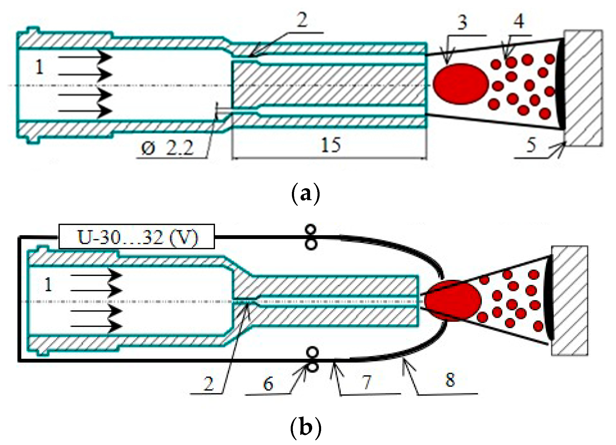
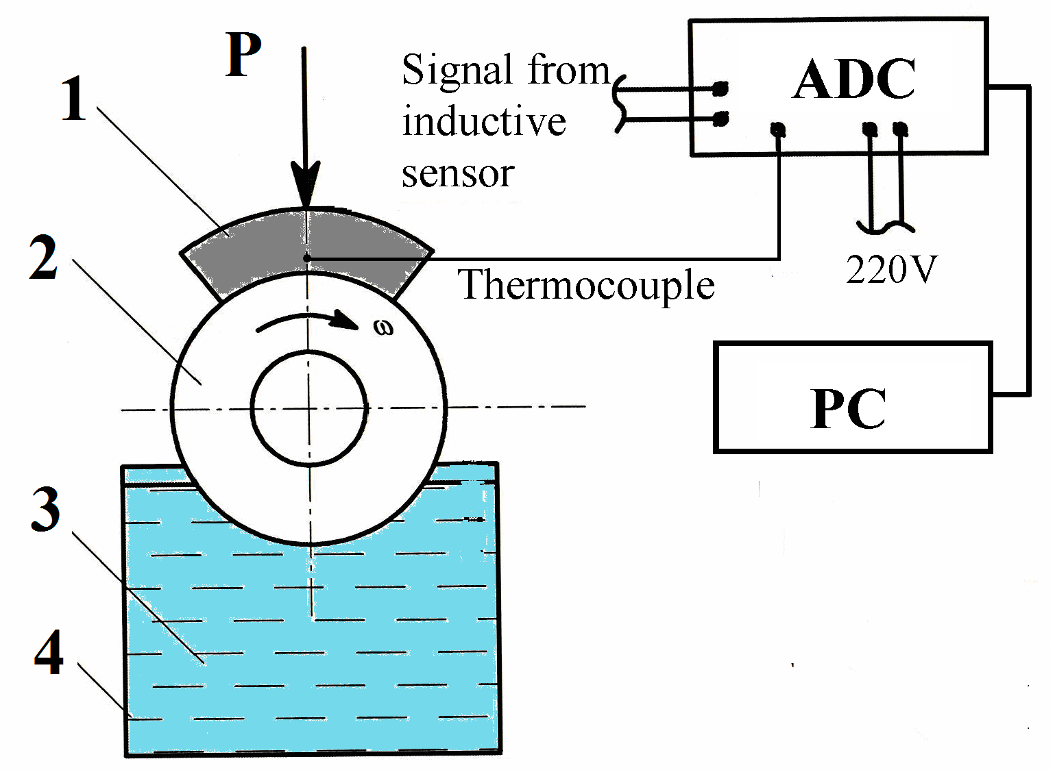
2. Materials and Methods
3. Results
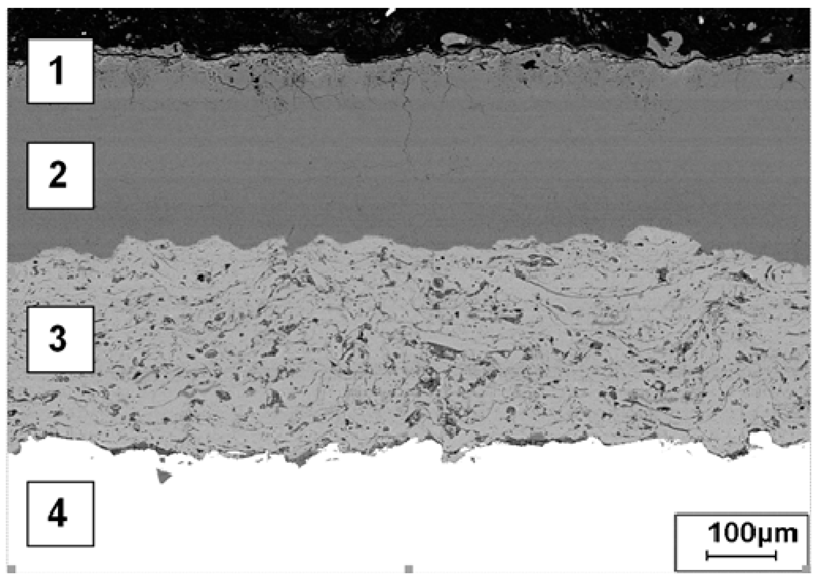
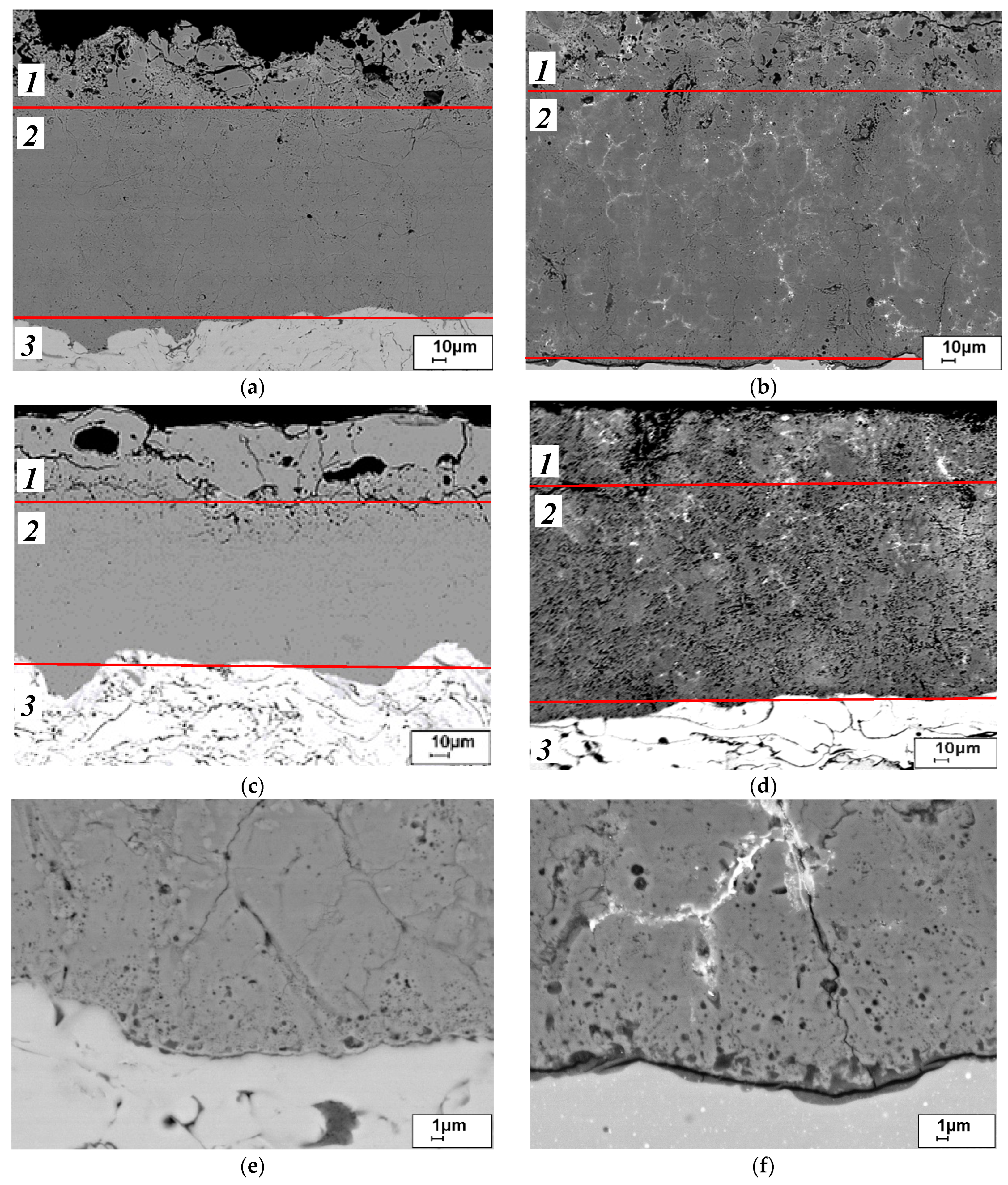
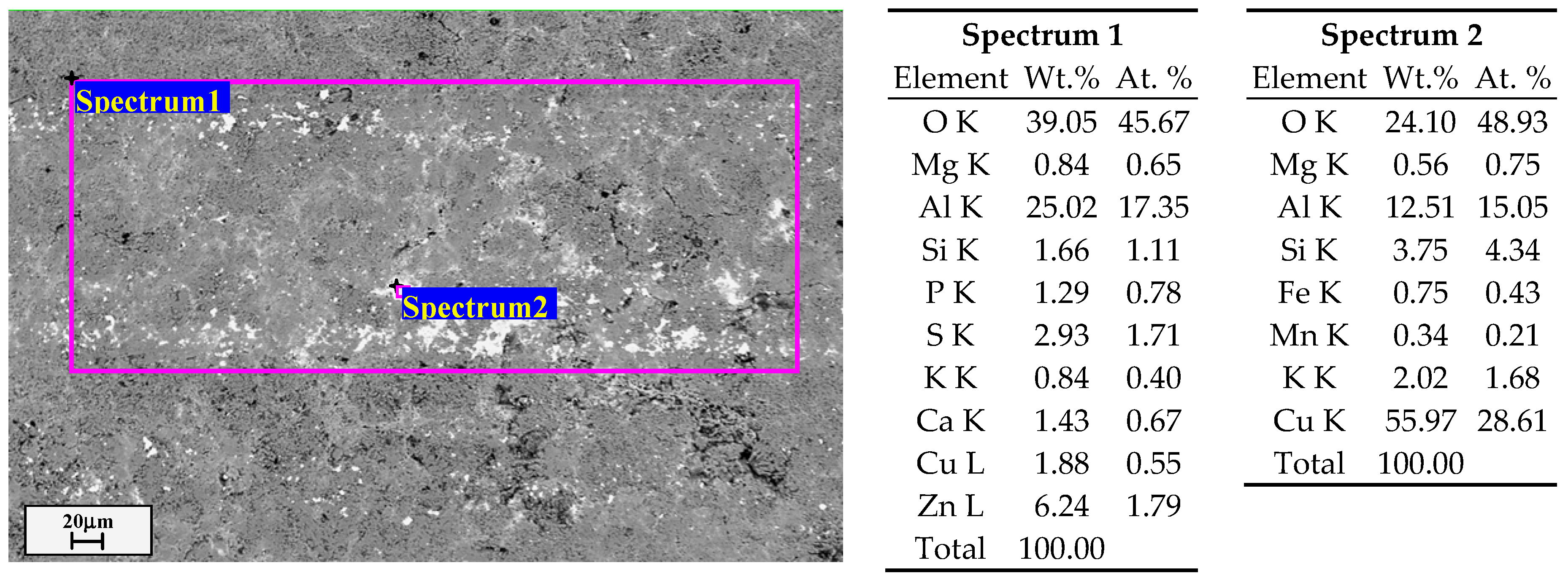
3.1. Microstructure of the Analyzed PEO Layers
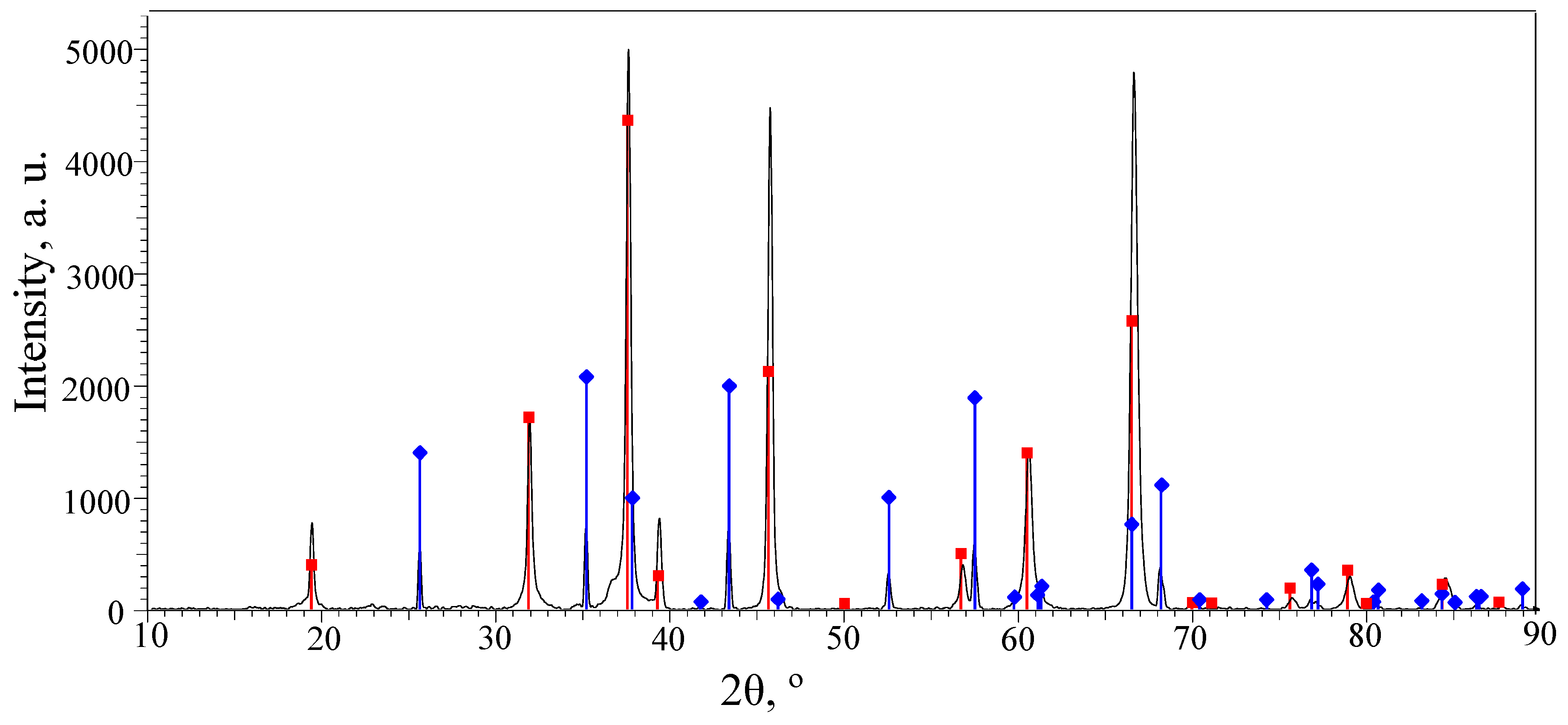
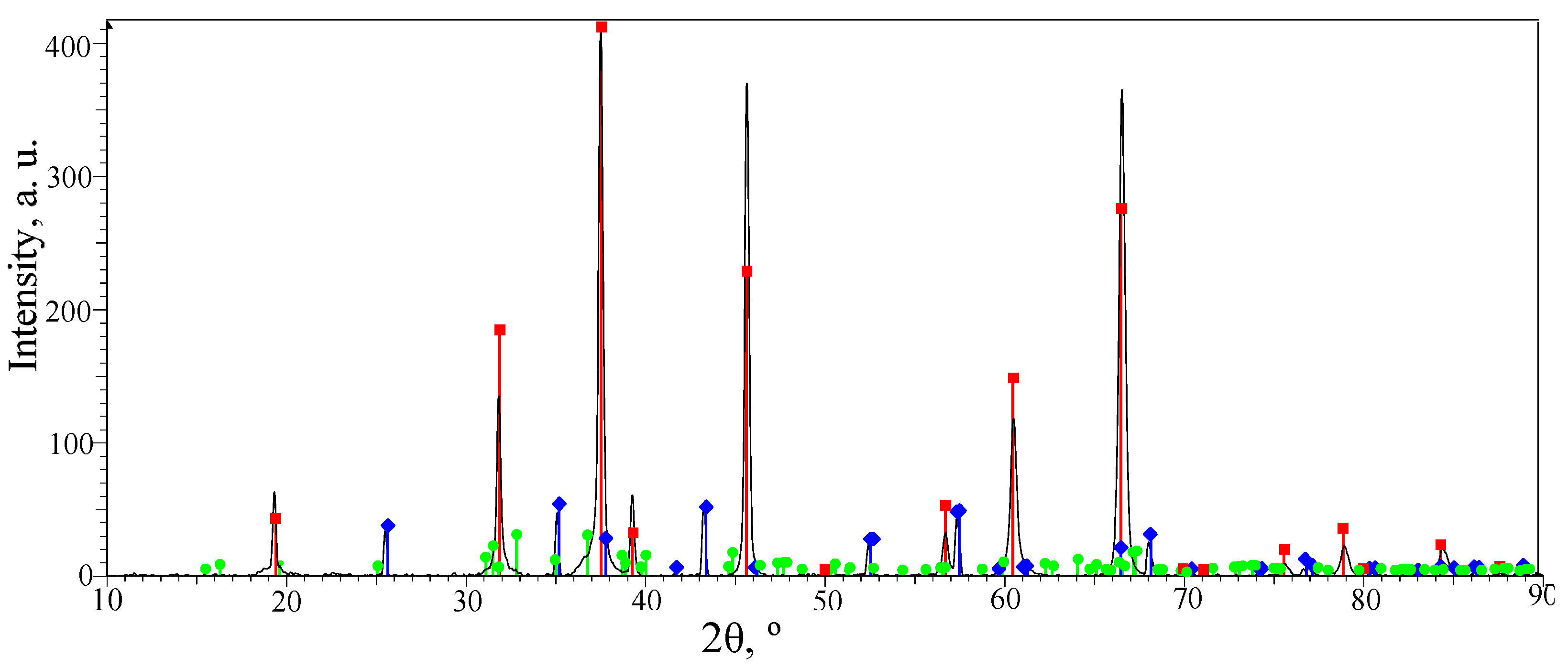
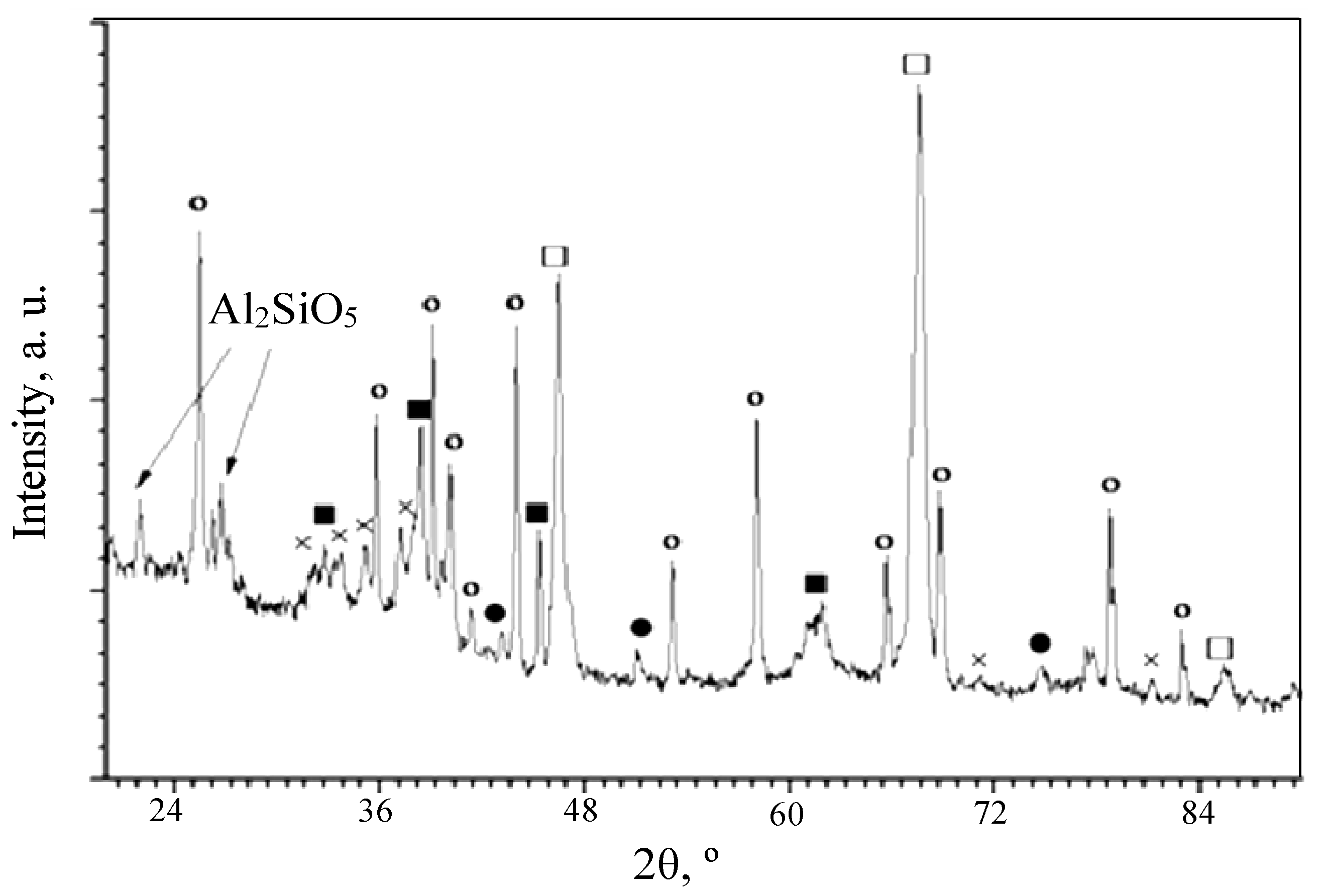
3.2. Phase Composition of the PEO Layers on the Surfaces of the ASCs
3.3. Tribological Characteristics of the PEO Layers
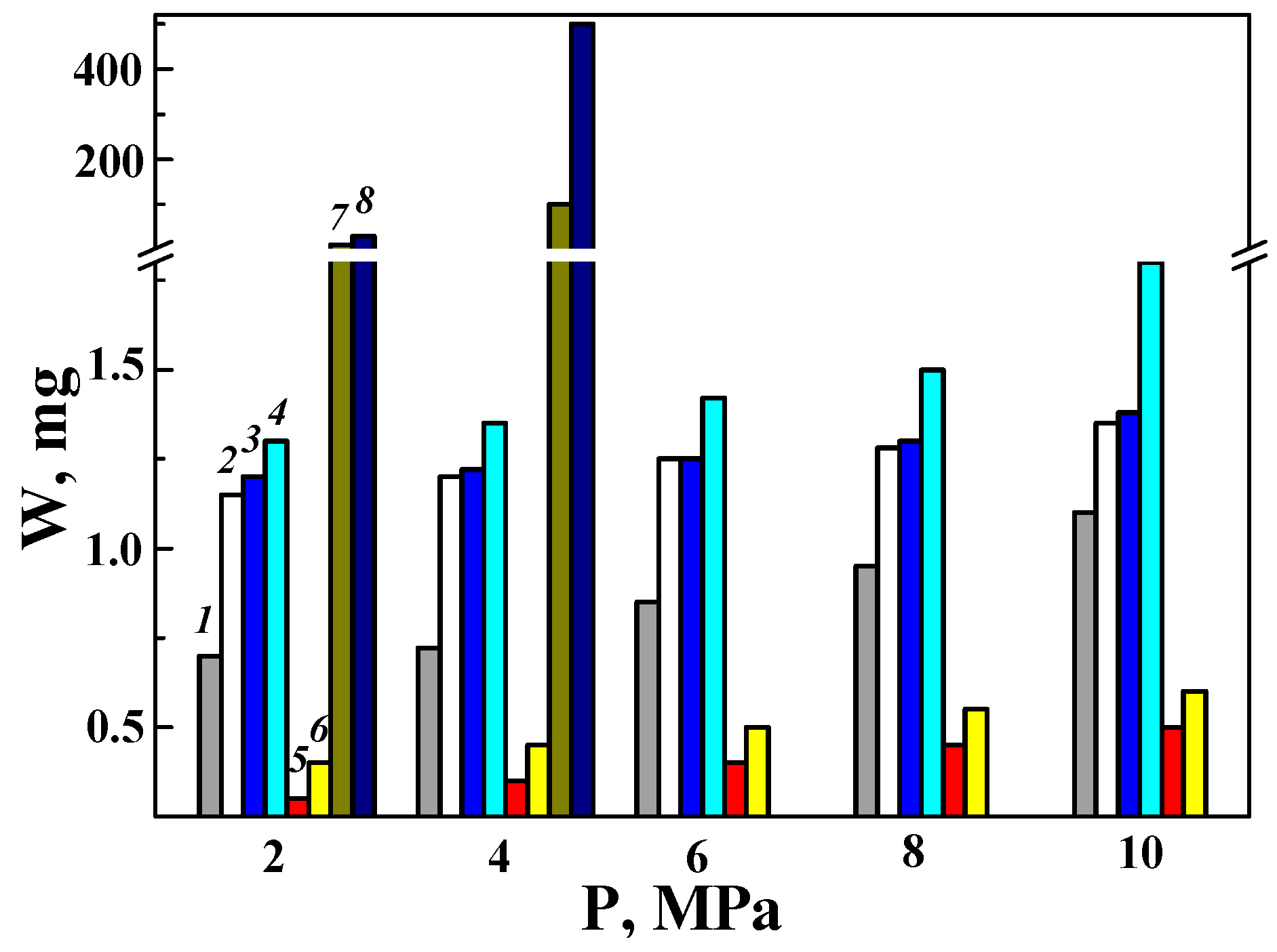
3.3.1. Wear Characteristics of a Disk Made of the D16 Alloy with a PEO Layer Paired with Various Counter Bodies (as Direct Friction Pairs)
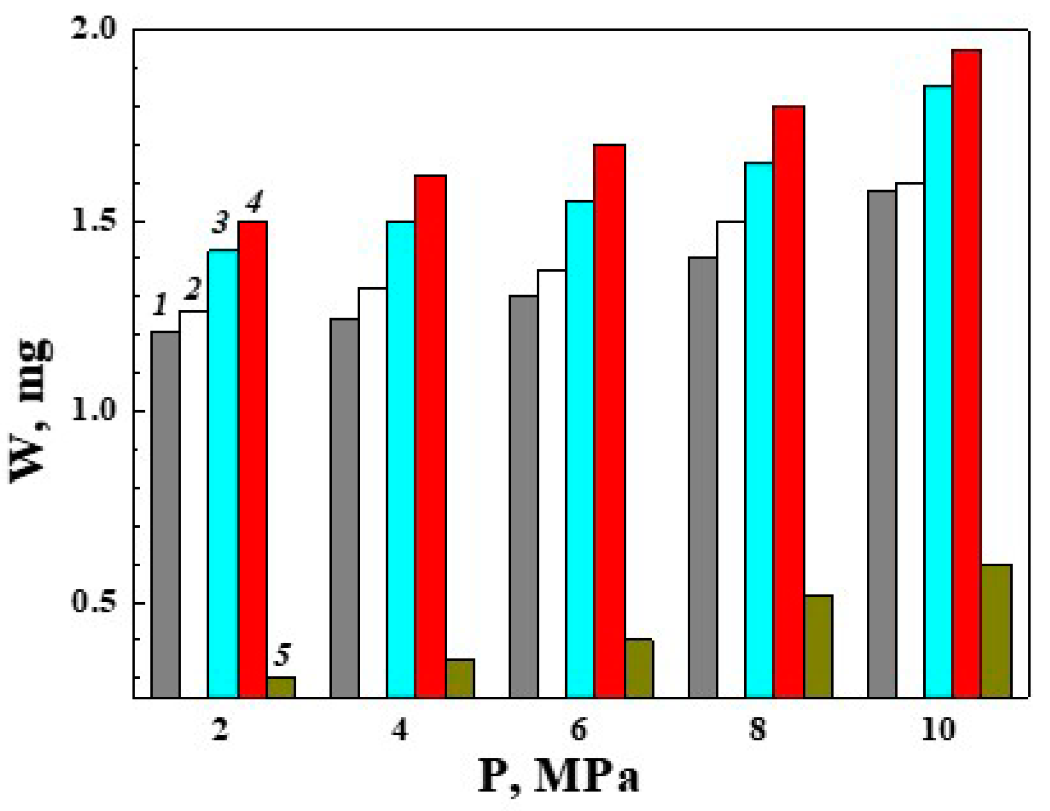
3.3.2. Wear Characteristics of a Counter Body Made of the D16 Alloy with a PEO Layer in Pairs with Various Disks (as Reverse Friction Pairs)
3.4. Reducing the Wear of the Disks with PEO Layers on ASCs due to Modification of the Lubricating Medium
3.5. Discussion of the Possibilities of Using the Described Results
4. Conclusions
Author Contributions
Funding
Institutional Review Board Statement
Informed Consent Statement
Data Availability Statement
Conflicts of Interest
References
- Jiang, J.; Islam, M.A.; Xie, Y.; Stack, M.M. Some thoughts on modelling abrasion-corrosion: Wear by hard particles in corrosive environments. J. Bio-Tribo-Corros. 2024, 10, 12. [Google Scholar] [CrossRef]
- Tartakovsky, E.D.; Goncharov, V.G.; Sapozhnikov, V.M. Analysis of the Effectiveness of Existing Methods of Repair 5D49 Diesel Engine Crankshafts. Available online: http://www.nbuv.gov.ua/portal/natural/Znpudazt/2009_107/n107-71 (accessed on 25 January 2024).
- Demin, A.Y.; Timofeeva, L.A.; Tymofeev, S.S.; Yagodinsky, E.S. Improved technologies at restoring crankshafts operational integrity for diesel vehicle destination. East. Eur. J. Enterp. Technol. 2014, 1, 60–64. [Google Scholar] [CrossRef]
- Netchaev, G.; Baliczkaya, O. Increasing the industrial locomotives resource by improving technologies of the crankshaft engine rehabilitation. Teka Comm. Mot. Energetics Agric. 2012, 12, 176–181. Available online: https://bibliotekanauki.pl/articles/792626 (accessed on 25 January 2024).
- Lewis, R.; Dwyer-Joyce, R.S. Wear of diesel engine inlet valves and seat inserts. Proc. Inst. Mech. Eng. Part D J. Automob. Eng. 2002, 216, 205–216. [Google Scholar] [CrossRef]
- Tomerlin, D. Repair welding of a rotating electrical machine’s broken shaft. J. Weld. Cut. 2019, 18, 198–203. Available online: https://www.scribd.com/document/433680505/WEANDC-2019-3-198 (accessed on 25 January 2024).
- Handbook of Reliability Prediction Procedures for Mechanical Equipment, Logistics Technology Support, Naval Surface Warfare Center (NSWC), Carderock Divizion, NSWC-11, West Bethesda, Maryland, May-2011, 20817–5700. Available online: https://extapps.ksc.nasa.gov/Reliability/Documents/HandbookofMechanicalReliability.pdf (accessed on 25 January 2024).
- Survilienė, S.; Češūnienė, A.; Juškėnas, R.; Selskienė, A.; Bučinskienė, D.; Kalinauskas, P.; Juškevičius, K.; Jurevičiūtė, I. The use of trivalent chromium bath to obtain a solar selective black chromium coating. Appl. Surface Sci. 2014, 305, 492–497. [Google Scholar] [CrossRef]
- Deflorian, F.; Rossi, S.; Fedrizzi, L.; Bonora, P.L. EIS study of organic coating on zinc surface pretreated with environmentally friendly products. Prog. Org. Coat. 2005, 52, 271–279. [Google Scholar] [CrossRef]
- Bellezze, T.; Roventi, G.; Fratesi, R. Electrochemical study on the corrosion resistance of Cr III-based conversion layers on zinc coatings. Surf. Coat. Technol. 2002, 155, 221–230. [Google Scholar] [CrossRef]
- Giovanardi, R.; Orlando, G. Chromium electrodeposition from Cr(III) aqueous solutions. Surf. Coat. Technol. 2011, 205, 3947–3955. [Google Scholar] [CrossRef]
- Sheibani Aghdam, A.; Allahkaram, S.R.; Mahdavi, S. Corrosion and tribological behavior of Ni–Cr alloy coatings electrodeposited on low carbon steel in Cr (III)–Ni (II) bath. Surf. Coat. Technol. 2015, 281, 144–149. [Google Scholar] [CrossRef]
- Rodríguez, R.J.; García, J.A.; Medrano, A.; Rico, M.; Sánchez, R.; Martínez, R.; Labrugère, C.; Lahaye, M.; Guette, A. Tribological behaviour of hard coatings deposited by arc-evaporation PVD. Vacuum 2002, 67, 559–566. [Google Scholar] [CrossRef]
- Mutyala, K.C.; Ghanbari, E.; Doll, G.L. Effect of deposition method on tribological performance and corrosion resistance characteristics of CrxN coatings deposited by physical vapor deposition. Thin Solid Films 2017, 636, 232–239. [Google Scholar] [CrossRef]
- Bembenek, M.; Makoviichuk, M.; Shatskyi, I.; Ropyak, L.; Pritula, I.; Gryn, L.; Belyakovskyi, V. Optical and mechanical properties of layered infrared interference filters. Sensors 2022, 22, 8105. [Google Scholar] [CrossRef] [PubMed]
- Matthes, K.-J.; Honig, T.; Wielage, B.; Wank, A.; Podlesak, H.; Pokhmurska, H. Laserstrahldispergieren von SiC in Aluminiumlegierungen zum partiellen Verschleißschutz. Schweiss. Schneid. 2006, 58, 119–122. [Google Scholar]
- Zhai, W.; Zhu, Z.; Zhou, W.; Nai, S.M.L.; Wei, J. Selective laser melting of dispersed TiC particles strengthened 316L stainless steel. Compos. Part B Eng. 2020, 199, 108291. [Google Scholar] [CrossRef]
- Kong, D.; Dong, C.; Ni, X.; Zhang, L.; Yao, J.; Man, C.; Cheng, X.; Xiao, K.; Li, X. Mechanical properties and corrosion behavior of selective laser melted 316L stainless steel after different heat treatment processes. J. Mater. Sci. Technol. 2019, 35, 1499–1507. [Google Scholar] [CrossRef]
- Khakbiz, M.; Simchi, A.; Bagheri, R. Analysis of the rheological behavior and stability of 316L stainless steel–TiC powder injection molding feedstock. Mater. Sci. Eng A. 2005, 407, 105–113. [Google Scholar] [CrossRef]
- Wank, A.; Schmengler, C.; Müller-Roden, K.; Beck, F.; Schläfer, T. Aptitude of different types of carbides for production of durable rough surfaces by laser dispersing. In Proceedings of the Thermal Spray International Thermal Spray, ITSC 2017, Düsseldorf, Germany, 7–9 June 2017; Paper No: itsc2017p0414. pp. 414–418, ISBN 9781510858220. [Google Scholar] [CrossRef]
- Student, M.; Hvozdetskyi, V.; Stupnytskyi, T.; Student, O.; Maruschak, P.; Prentkovskis, O.; Skačkauskas, P. Mechanical properties of arc coatings sprayed with cored wires with different charge compositions. Coatings 2022, 12, 925. [Google Scholar] [CrossRef]
- Stupnyts’kyi, T.R.; Student, M.M.; Pokhmurs’ka, H.V.; Hvozdets’kyi, V.M. Optimization of the chromium content of powder wires of the Fe–Cr–C and Fe–Cr–B systems according to the corrosion resistance of electric-arc coatings. Mater. Sci. 2016, 52, 165–172. [Google Scholar] [CrossRef]
- Student, M.M.; Pokhmurs’ka, H.V.; Zadorozhna, K.R.; Veselivs’ka, H.H.; Hvozdets’kyi, V.M.; Sirak, Y.Y. Corrosion Resistance of VC–FeCr and VC–FeCrCo Coatings Obtained by Supersonic Gas-Flame Spraying. Mater. Sci. 2019, 54, 535–541. [Google Scholar] [CrossRef]
- Liu, N.; Liu, Q.; Li, Z.; Bai, Y.; Sun, Y.W.; Li, Z.D.; Bao, M.Y.; Zhan, H.; Guo, D.G.; Ma, Y.S. Tribological behavior of plasma-sprayed metal based solid self-lubricating coatings under heavy load. Wear 2021, 486–487, 204108. [Google Scholar] [CrossRef]
- Zhao, X.; Li, S.; Hou, G.; An, Y.; Zhou, H.; Chen, J. Influence of doping graphite on microstructure and tribological properties of plasma sprayed 3Al2O3–2SiO2 coating. Tribol. Int. 2016, 101, 168–177. [Google Scholar] [CrossRef]
- Kumar, H.; Bhaduri, G.A.; Manikandan, S.G.K.; Kamaraj, M.; Shiva, S. Microstructural characterization and tribological properties of atmospheric plasma sprayed high entropy alloy coatings. J. Therm. Spray Technol. 2022, 31, 1956–1974. [Google Scholar] [CrossRef]
- Prysyazhnyuk, P.; Di Tommaso, D. The thermodynamic and mechanical properties of Earth-abundant metal ternary boride Mo2(Fe,Mn)B2 solid solutions for impact- and wear-resistant alloys. Mater. Adv. 2023, 4, 3822–3838. [Google Scholar] [CrossRef]
- Hutsaylyuk, V.; Student, M.; Zadorozhna, K.; Student, O.; Veselivska, H.; Gvosdetskii, V.; Maruschak, P.; Pokhmurska, H. Improvement of wear resistance of aluminum alloy by HVOF method. J. Mater. Res. Technol. 2020, 9, 16367–16377. [Google Scholar] [CrossRef]
- Fukumoto, M.; Wada, Y.; Umemoto, M.; Okane, I. Effect of connected pores on the corrosion behavior of plasma sprayed alumina coatings. Surf. Coat. Technol. 1989, 39–40, 711–720. [Google Scholar] [CrossRef]
- Vlasiy, O.; Mazurenko, V.; Ropyak, L.; Rogal, O. Improving the aluminum drill pipes stability by optimizing the shape of protector thickening. East.-Eur. J. Enterp. Technol. 2017, 1, 25–31. [Google Scholar] [CrossRef]
- Darband, G.B.; Aliofkhazraei, M.; Hamghalam, P.; Valizade, N. Plasma-electrolytic oxidation of magnesium and its alloys: Mechanism, properties and applications. J. Magnes. Alloys 2017, 5, 74–132. [Google Scholar] [CrossRef]
- Ropyak, L.; Shihab, T.; Velychkovych, A.; Bilinskyi, V.; Malinin, V.; Romaniv, M. Optimization of plasma electrolytic oxidation technological parameters of deformed aluminum alloy D16T in flowing electrolyte. Ceramics 2023, 6, 146–167. [Google Scholar] [CrossRef]
- Ropyak, L.; Shihab, T.; Velychkovych, A.; Dubei, O.; Tutko, T.; Bilinskyi, V. Design of a two-layer Al–Al2O3 coating with an oxide layer formed by the plasma electrolytic oxidation of Al for the corrosion and wear protections of steel. Prog. Phys. Met. 2023, 24, 319–365. [Google Scholar] [CrossRef]
- Shatskyi, I.; Makoviichuk, M.; Ropyak, L.; Velychkovych, A. Analytical model of deformation of a functionally graded ceramic coating under local load. Ceramics 2023, 6, 1879–1893. [Google Scholar] [CrossRef]
- Nie, X.; Meletis, E.I.; Jiang, J.C.; Layland, A.; Yerokhin, A.L.; Mattews, A. Abrasive wear/corrosion properties and TEM analysis of Al2O3 coatings fabricated using plasma electrolysis. Surf. Coat. Technol. 2002, 149, 245–251. [Google Scholar] [CrossRef]
- Wei, T.; Yan, F.; Tian, J. Characterisation and wear and corrosion-resistance of microarc oxidation ceramic coatings on aluminum alloy. J. Alloys Compd. 2005, 389, 169–176. [Google Scholar] [CrossRef]
- Yerokhin, A.L.; Nie, X.; Leyland, A.; Matthews, A.; Dowey, S.J. Plasma electrolysis for surface engineering. Surf. Coat. Technol. 1999, 122, 73–93. [Google Scholar] [CrossRef]
- Hutsaylyuk, V.; Student, M.; Dovhunyk, V.; Posuvailo, V.; Student, O.; Maruschak, P.; Koval’chuck, I. Effect of hydrogen on the wear resistance of steels upon contact with plasma electrolytic oxidation layers synthesized on aluminum alloys. Metals 2019, 9, 280. [Google Scholar] [CrossRef]
- Simchen, F.; Sieber, M.; Kopp, A.; Lampke, T. Introduction to plasma electrolytic oxidation—An overview of the process and applications. Coatings 2020, 10, 628. [Google Scholar] [CrossRef]
- Chumalo, H.V.; Posuvailo, V.M.; Kharchenko, E.V. Iinfluence of the composition of electrolytes on the properties of plasma-electrolytic oxide coatings on light alloys. Mater. Sci. 2020, 56, 27–33. [Google Scholar] [CrossRef]
- Posuvailo, V.M.; Klapkiv, M.D.; Student, M.M.; Sirak, Y.Y.; Pokhmurska, H.V. Gibbs energy calculation of electrolytic plasma channel with inclusions of copper and copper oxide with Al-base. Mater. Sci. Eng. 2017, 181, 012045. [Google Scholar] [CrossRef]
- Rodriguez, L.; Paris, J.-Y.; Denape, J.; Delbé, K. Micro-arcs oxidation layer formation on aluminium and coatings tribological properties—A review. Coatings 2023, 13, 373. [Google Scholar] [CrossRef]
- Hutsaylyuk, V.; Student, M.; Posuvailo, V.; Student, O.; Sirak, Y.; Hvozdets’kyi, V.; Maruschak, P.; Veselivska, H. The properties of oxide-ceramic layers with Cu and Ni inclusions synthesizing by PEO method on top of the gas-spraying coatings on aluminium alloys. Vacuum 2020, 179, 109514. [Google Scholar] [CrossRef]
- Tu, C.; Chen, X.; Liu, C.; Li, D. Plasma electrolytic oxidation coatings of a 6061 Al alloy in an electrolyte with the addition of K2ZrF6. Materials 2023, 16, 4142. [Google Scholar] [CrossRef] [PubMed]
- Zhang, Y.; Wang, Q.; Ye, R.; Ramachandran, C.S. Plasma electrolytic oxidation of cold spray kinetically metallized CNT-Al coating on AZ91-Mg alloy: Evaluation of mechanical and surficial characteristics. J. Alloys Compd. 2022, 892, 162094. [Google Scholar] [CrossRef]
- Rao, Y.; Wang, Q.; Chen, J.; Ramachandran, C.S. Abrasion, sliding wear, corrosion, and cavitation erosion characteristics of a duplex coating formed on AZ31 Mg alloy by sequential application of cold spray and plasma electrolytic oxidation techniques. Mater. Today Commun. 2021, 26, 101978. [Google Scholar] [CrossRef]
- Martin, J.; Akoda, K.; Ntomprougkidis, V.; Ferry, O.; Maizeray, A.; Bastien, A.; Brenot, P.; Ezo’o, G.; Henrion, G. Duplex surface treatment of metallic alloys combining cold-spray and plasma electrolytic oxidation technologies. Surf. Coat. Technol. 2020, 392, 125756. [Google Scholar] [CrossRef]
- Martin, J.; Maizeray, A.; Tousch, C.; Da, S.; Marcos, G.; Czerwiec, T.; Henrion, G. A new strategy to prepare alumina-zirconia composite or multilayered coatings by combining cold-spray deposition and plasma electrolytic oxidation. Mater. Today Commun. 2023, 36, 106676. [Google Scholar] [CrossRef]
- Champagne, V.; Helfritch, D. The unique abilities of cold spray deposition. Int. Mater. Rev. 2016, 61, 437–455. [Google Scholar] [CrossRef]
- Moridi, A.; Hassani-Gangaraj, S.M.; Guagliano, M.; Dao, M. Cold spray coating: Review of material systems and future perspectives. Surf. Eng. 2014, 30, 69–395. [Google Scholar] [CrossRef]
- Ralls, A.; Gillespy, R.; Menezes, P.V.; Men, P.L. Unraveling electrochemical mechanisms in plasma electrolytic oxidation of cold spray additively manufactured stainless steel. J. Mater. Eng. Perform. 2023, 1–19. [Google Scholar] [CrossRef]
- Gu, W.; Shen, D.; Wang, Y.; Chen, G.; Feng, W.; Zhang, G.; Fan, S.; Liu, C.; Yang, S. Deposition of duplex Al2O3/aluminum coatings on steel using a combined technique of arc spraying and plasma electrolytic oxidation. Appl. Surf. Sci. 2006, 252, 2927–2932. [Google Scholar] [CrossRef]
- Wu, Z.; Xia, Y.; Li, G.; Xu, F. Structure and mechanical properties of ceramic coatings fabricated by plasma electrolytic oxidation on aluminized steel. Appl. Surf. Sci. 2007, 253, 8398–8403. [Google Scholar] [CrossRef]
- Student, M.M.; Pohrelyuk, I.M. Modification of the surfaces of aluminum and titanium alloys aimed at the improvement of their wear resistance and tribological characteristics. Mater. Sci. 2021, 57, 377–386. [Google Scholar] [CrossRef]
- Dong, H.; Li, Q.; Xie, D.; Jiang, W.; Ding, H.; Wang, S.; An, L. Forming characteristics and mechanisms of micro-arc oxidation coatings on magnesium alloys based on different types of single electrolyte solutions. Ceram. Int. 2023, 49, 32271–32281. [Google Scholar] [CrossRef]
- Habazaki, H.; Tsunekawa, S.; Tsuji, E.; Nakayama, T. Formation and characterization of wear-resistant PEO coatings formed on β-titanium alloy at different electrolyte temperatures. Appl. Surf. Sci. 2012, 259, 711–718. [Google Scholar] [CrossRef]
- Kostelac, L.; Pezzato, L.; Colusso, E.; Natile, M.M.; Brunelli, K.; Dabalà, M. Black PEO coatings on titanium and titanium alloys produced at low current densities. Appl. Sci. 2023, 13, 12280. [Google Scholar] [CrossRef]
- Ramazanova, Z.M.; Zamalitdinova, M.G. Study of the properties of qxide coatings formed on titanium by plasma electrolytic oxidation method. Eurasian Chem. Technol. J. 2020, 22, 51–58. [Google Scholar] [CrossRef]
- Arrabal, R.; Matykina, E.; Hashimoto, T.; Skeldon, P.; Thompson, G.E. Characterization of AC PEO coatings on magnesium alloys. Surf. Coat. Technol. 2009, 203, 2207–2220. [Google Scholar] [CrossRef]
- Cui, S.; Han, J.; Du, Y.; Li, W. Corrosion resistance and wear resistance of plasma electrolytic oxidation coatings on metal matrix composites. Surf. Coat. Technol. 2007, 201, 5306–5309. [Google Scholar] [CrossRef]
- Alshujery, M.K.; Al-Saadie, K.A.S. Corrosion inhibition of aluminum 6061 alloy by a micro arc oxidation modified with incorporated zinc oxide nanoparticles. AIP Conf. Proc. 2023, 2830, 020002. [Google Scholar] [CrossRef]
- Lee, J.-M.; Kang, S.-B.; Han, J. Dry sliding wear of MAO-coated A356/20 vol.% SiCp composites in the temperature range 25–180 °C. Wear 2008, 264, 75–85. [Google Scholar] [CrossRef]
- Lu, X.; Mohedano, M.; Blawert, C.; Matykina, E. Plasma electrolytic oxidation coatings with particle additions—A review. Surf. Coat. Technol. 2016, 307, 1165–1182. [Google Scholar] [CrossRef]
- Xue, W.; Jin, Q.; Zhu, Q.; Hua, M.; Ma, Y. Anti-corrosion microarc oxidation coatings on SiCP AZ31 magnesium matrix composite. J. Alloys Compd. 2009, 482, 208–212. [Google Scholar] [CrossRef]
- Mingo, B.; Arrabal, R.; Mohedano, M.; Pardo, A. Corrosion and wear of PEO coated AZ91/SiC composites. Surf. Coat. Technol. 2017, 309, 1023–1032. [Google Scholar] [CrossRef]
- Matykina, E.; Arrabal, R.; Skeldon, P.; Thompson, G.E. Investigation of the growth processes of coatings formed by AC plasma electrolytic oxidation of aluminium. Electrochim. Acta 2009, 54, 6767–6778. [Google Scholar] [CrossRef]
- Dehnavi, V.; Shoesmith, D.W.; Li, B.; Yari, M.; Yang, X.; Rohani, S. Corrosion properties of plasma electrolytic oxidation coatings on an aluminium alloy—The effect of the PEO process stage. Mater. Chem. Phys. 2015, 161, 49–58. [Google Scholar] [CrossRef]
- Mingo, B.; Arrabal, R.; Mohedano, M.; Llamazares, Y.; Matykina, E.; Yerokhin, A.; Pardo, A. Influence of sealing post-treatments on the corrosion resistance of PEO coated AZ91 magnesium alloy. Appl. Surf. Sci. 2018, 433, 653–667. [Google Scholar] [CrossRef]
- Egorkin, V.S.; Gnedenkov, S.V.; Sinebryukhov, S.L.; Vyaliy, I.E.; Gnedenkov, A.S.; Chizhikov, R.G. Increasing thickness and protective properties of PEO-coatings on aluminum alloy. Surf. Coat. Technol. 2018, 334, 29–42. [Google Scholar] [CrossRef]
- Student, M.; Gvozdetsky, V.; Student, O.; Prentkovskis, O.; Maruschak, P.; Olenyuk, O.; Titova, L. The effect of increasing the air flow pressure on the properties of coatings during the arc spraying of cored wires. J. Mech. Eng.-Stroj. Časopis 2019, 69, 133–146. [Google Scholar] [CrossRef]
- Gurvich, L.V.; Veyts, I.V.; Medvedev, V.A.; Khachkuruzov, G.A.; Yungman, V.S.; Bergman, G.A.; Baybuz, V.F.; Iorish, V.S.; Yurkov, G.N.; Gorbov, S.I.; et al. Thermodynamic Properties of Individual Substances; Hemisphere Publishing Corp.: New York, NY, USA, 1989; Volume 1, Part 2; 340p. [Google Scholar]
- Gualtieri, A.F.; Gatta, G.D.; Arletti, R.; Artioli, G.; Ballirano, P.; Cruciani, G.; Guagliardi, A.; Malferrari, D.; Masciocchi, N.; Scardi, P. Quantitative phase analysis using the Rietveld method: Towards a procedure for checking the reliability and quality of the results. Period. Miner. 2019, 88, 147–151. [Google Scholar] [CrossRef]
- Altomare, A.; Cuocci, C.; Gatta, G.D.; Moliterni, A.; Rizzi, R. Methods of crystallography: Powder X-ray diffraction. EMU Notes Mineral. 2017, 19, 79–138. [Google Scholar] [CrossRef]
- Bish, D.L.; Howard, S.A. Quantitative phase analysis using the Rietveld method. J. Appl. Crystallogr. 1988, 21, 86–91. [Google Scholar] [CrossRef]
- Ilie, F. Diffusion and mass transfer mechanisms during frictional selective transfer. Int. J. Heat Mass Transf. 2018, 116, 1260–1265. [Google Scholar] [CrossRef]
- Chen, Q.; Lei, M.; Chen, Y.; Deng, Y.; Chen, M.-A. Preparation of a thick sponge-like structured amorphous silica ceramic coating on 6061 aluminum alloy by plasma electrolytic oxidation in TEOS solution. Ceram. Int. 2023, 49, 32679–32693. [Google Scholar] [CrossRef]
- Yang, X.; Chen, L.; Jin, X.; Du, J.; Xue, W. Influence of temperature on tribological properties of microarc oxidation coating on 7075 aluminium alloy at 25 °C–300 °C. Ceram. Int. 2019, 45, 12312–12318. [Google Scholar] [CrossRef]
- Shirani, A.; Joy, T.; Rogov, A.; Lin, M.; Yerokhin, A.; Mogonye, J.-E.; Korenyi-Both, A.; Aouadi, S.M.; Voevodin, A.A.; Berman, D. PEO-Chameleon as a potential protective coating on cast aluminum alloys for high-temperature applications. Surf. Coat. Technol. 2020, 397, 126016. [Google Scholar] [CrossRef]
- Kirik, G.V.; Gaponova, O.P.; Tarelnyk, V.B.; Myslyvchenko, O.M.; Antoszewski, B. Quality Analysis of Aluminized Surface Layers Produced by Electrospark Deposition. Powder Metall. Met. Ceram. 2018, 56, 688–696. [Google Scholar] [CrossRef]
- Zhang, F.; Chen, J.; Yan, S.; Yu, G.; He, J.; Yin, F. Plasma spraying Ti–Al–C based composite coatings from Ti/Al/graphite agglomerates: Synthesis, characterization and reaction mechanism. Vacuum 2022, 200, 111036. [Google Scholar] [CrossRef]
- Rukanskis, M.; Padgurskas, J.; Mihailov, V.; Rukuiža, R.; Žunda, A.; Baltakys, K.; Tuckute, S. Investigation of the Lubricated Tribo-System of Modified Electrospark Coatings. Coatings 2023, 13, 825. [Google Scholar] [CrossRef]


 —α-Al2O3 with a hexagonal lattice;
  —γ-Al2O3 with a cubic lattice;
  —Al2.427O3.64.
—α-Al2O3 with a hexagonal lattice; —γ-Al2O3 with a cubic lattice; —Al2.427O3.64.
—Al2.427O3.64.
—α-Al2O3 with a hexagonal lattice; —γ-Al2O3 with a cubic lattice; —Al2.427O3.64.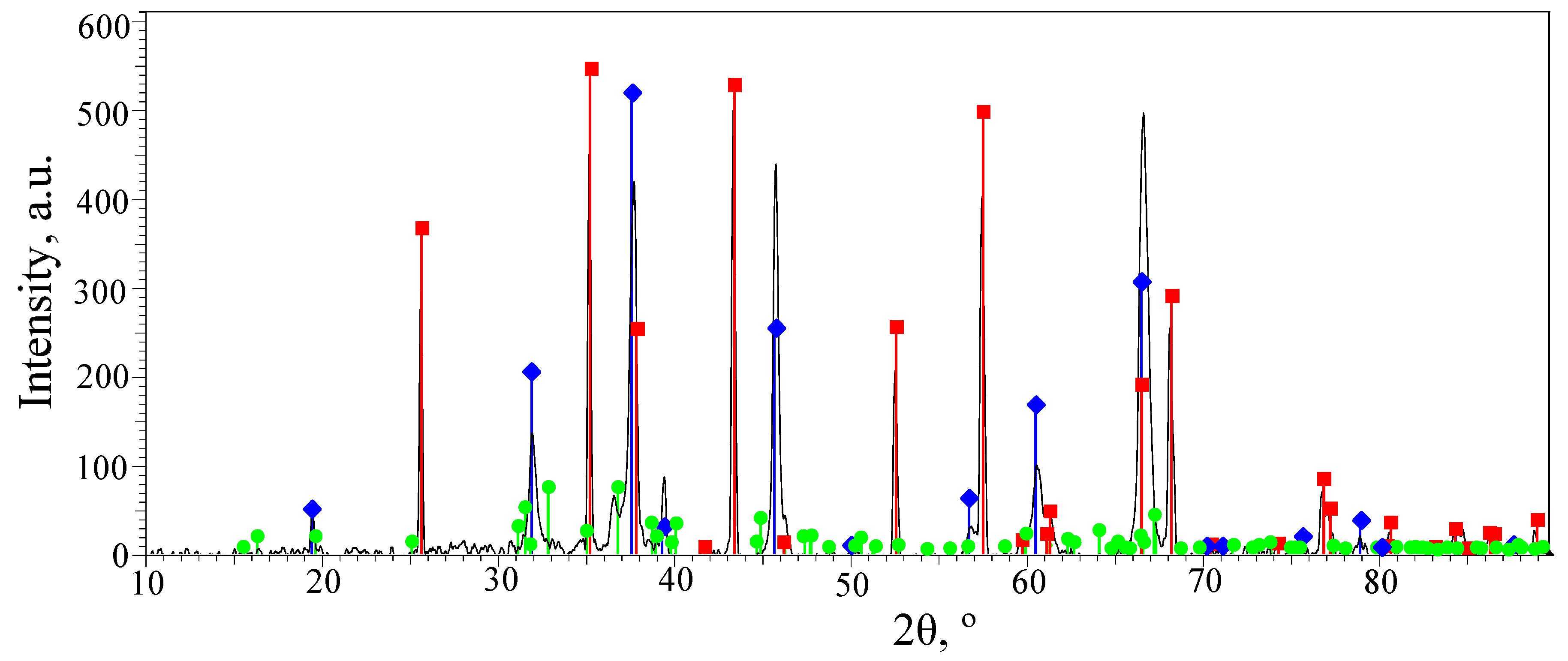 —α-Al2O3 with a hexagonal lattice; —γ-Al2O3 with a cubic lattice.
—α-Al2O3 with a hexagonal lattice; —γ-Al2O3 with a cubic lattice.
—α-Al2O3 with a hexagonal lattice; —γ-Al2O3 with a cubic lattice. —α-Al2O3 with a hexagonal lattice; —γ-Al2O3 with a cubic lattice; —Al2.427O3.64.
—α-Al2O3 with a hexagonal lattice; —γ-Al2O3 with a cubic lattice; —Al2.427O3.64.
—α-Al2O3 with a hexagonal lattice; —γ-Al2O3 with a cubic lattice; —Al2.427O3.64.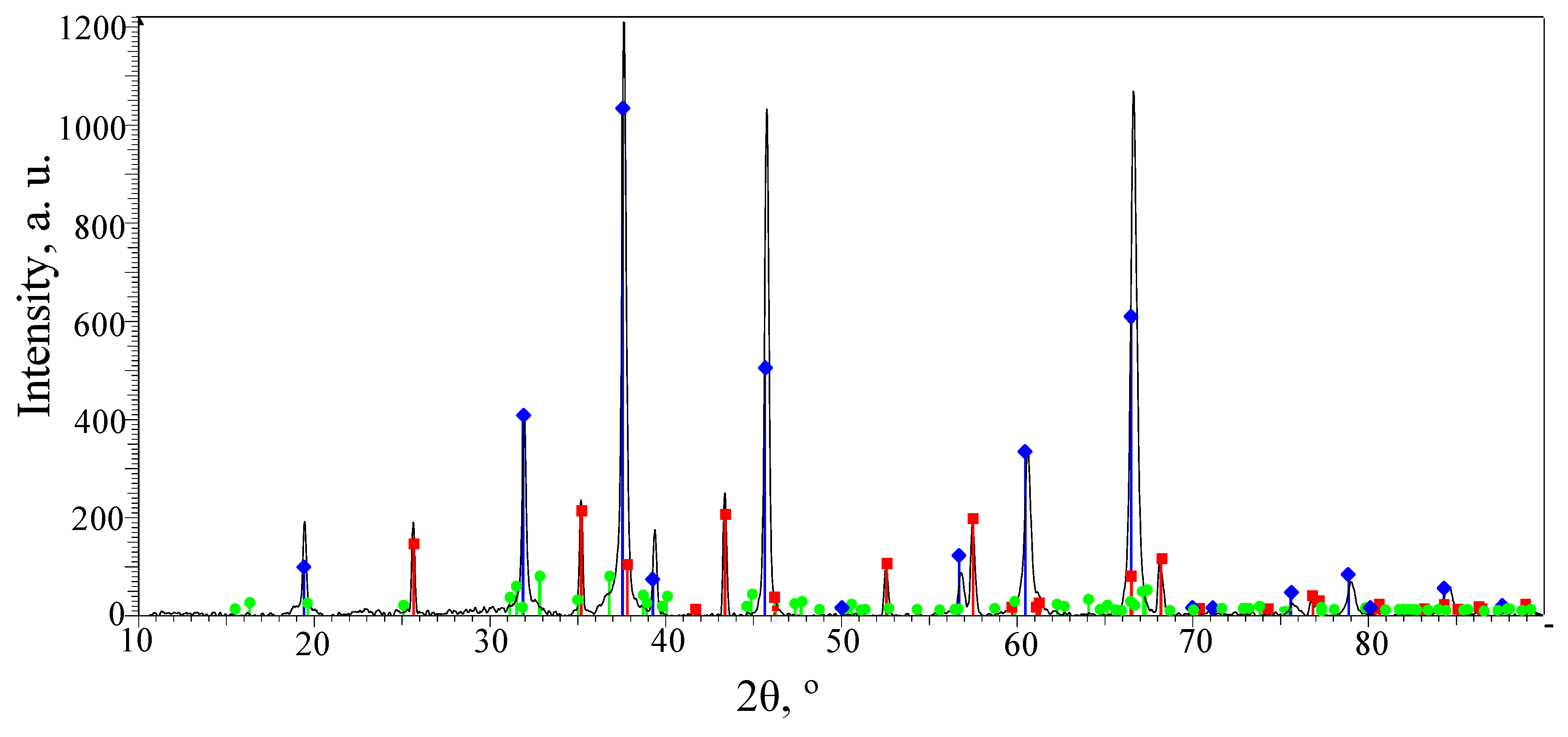 —α-Al2O3 with a hexagonal lattice; —γ-Al2O3 with a cubic lattice; —Al2.427O3.64.
—α-Al2O3 with a hexagonal lattice; —γ-Al2O3 with a cubic lattice; —Al2.427O3.64.
—α-Al2O3 with a hexagonal lattice; —γ-Al2O3 with a cubic lattice; —Al2.427O3.64.


| Fe | Si | Mn | Cr | Ti | Al | Cu | Mg | Zn | |
|---|---|---|---|---|---|---|---|---|---|
| D16 | 0.22 | 0.41 | 0.85 | 0.05 | 0.12 | 93.11 | 4.14 | 1.05 | 0.05 |
| AMg6 | 0.32 | 0.31 | 0.57 | - | 0.05 | 93.25 | 0.10 | 6.15 | 0.15 |
| A0 | 0.21 | 0.18 | - | - | - | 99.6 | 0.01 | - | - |
| Phase | SG | a | b | c |
|---|---|---|---|---|
| α-Al2O3 | R-3c | 4.75980 | 4.75980 | 12.99240 |
| γ-Al2O3 | Fd-3m | 7.94800 | 7.94800 | 7.94800 |
| Al2.427O3.64 | C2/m | 11.85400 | 2.90400 | 5.62200 |
Disclaimer/Publisher’s Note: The statements, opinions and data contained in all publications are solely those of the individual author(s) and contributor(s) and not of MDPI and/or the editor(s). MDPI and/or the editor(s) disclaim responsibility for any injury to people or property resulting from any ideas, methods, instructions or products referred to in the content. |
© 2024 by the authors. Licensee MDPI, Basel, Switzerland. This article is an open access article distributed under the terms and conditions of the Creative Commons Attribution (CC BY) license (https://creativecommons.org/licenses/by/4.0/).
Share and Cite
Hvozdets’kyi, V.; Padgurskas, J.; Student, M.; Pohrelyuk, I.; Student, O.; Zadorozhna, K.; Tkachuk, O.; Rukuiža, R. The Tribological Properties of Plasma Electrolytic Oxidation Layers Synthesized on Arc Spray Coatings on Aluminum Alloys in Contact with Various Friction Materials. Coatings 2024, 14, 460. https://doi.org/10.3390/coatings14040460
Hvozdets’kyi V, Padgurskas J, Student M, Pohrelyuk I, Student O, Zadorozhna K, Tkachuk O, Rukuiža R. The Tribological Properties of Plasma Electrolytic Oxidation Layers Synthesized on Arc Spray Coatings on Aluminum Alloys in Contact with Various Friction Materials. Coatings. 2024; 14(4):460. https://doi.org/10.3390/coatings14040460
Chicago/Turabian StyleHvozdets’kyi, Volodymyr, Juozas Padgurskas, Mykhailo Student, Iryna Pohrelyuk, Oleksandra Student, Khrystyna Zadorozhna, Oleh Tkachuk, and Raimundas Rukuiža. 2024. "The Tribological Properties of Plasma Electrolytic Oxidation Layers Synthesized on Arc Spray Coatings on Aluminum Alloys in Contact with Various Friction Materials" Coatings 14, no. 4: 460. https://doi.org/10.3390/coatings14040460