4.1. Preparation of Ag/Ni Contact Materials
For AgNi materials, as the Ni content increases, higher temperatures and longer times are required to dissolve the original Ni particles in the Ag matrix. During condensation, it is easy to form a Ni-enriched area and some Ni oxide on the contact’s surface. Therefore, an increase in Ni content will result in a significantly faster rise in the material’s contact resistance. Even at a high temperature of 2000 °C, the solubility of Ni in Ag is only about 10%. When the nickel content in the material exceeds 10%, it becomes challenging for the “dissolution precipitation effect” to fully encapsulate all the original Ni particles [
24]. In this case, the formation of Ni-enriched zones and the generation of oxides are inevitable, leading to a sharp increase in contact resistance. When the Ni content exceeds 20%, the above situation almost inevitably occurs. Therefore, the preparation of an undoped AgNi contact material with a 15% Ni content was chosen, and Ni powder of equal quality was used to replace the Nb powder for doping.
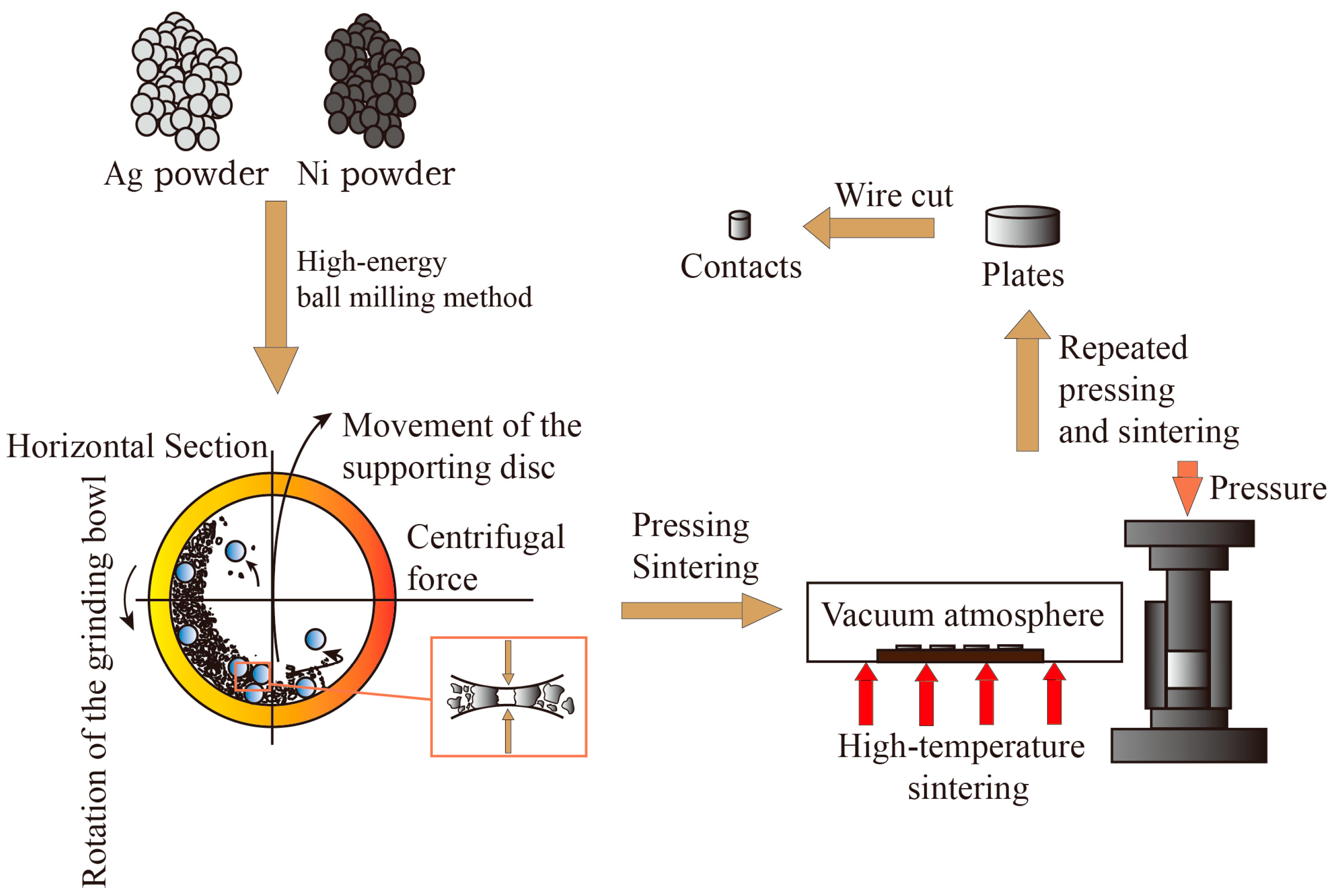
In this paper, AgNi contact materials were prepared by combining the high-energy ball milling method and powder metallurgy method. The prepared AgNi contact materials weighed 10 g. The atomic ratio of the additives to the mass ratio is shown in
Table 1. The specific preparation process is as follows:
The powders were mixed in a high-energy ball mill by first thoroughly mixing half of the Ag powder with the Ni powder. Then, the Nb powder was added to the mixed powder and was homogeneously mixed with the remaining Ag powder again using high-energy ball milling. All of the aforementioned steps necessitated adding a corresponding amount of powder to the agate ball milling bottle, followed by the addition of agate balls, with the ball-to-powder ratio set at 50:1. Agate balls were selected as the grinding material to prevent impurities during the ball milling and mixing process, thereby enhancing the purity of the samples. Then, 3 mL of ethanol was added to the ball milling jar as a grinding medium to enhance the comminution efficiency. This addition helps refine the powder particles and prevent oxidation of the powder. The speed was set at 200 rpm and 500 rpm, and the ball milling time was 1 h. The ball milling jars were rotated 360° for multidimensional and multidirectional movement.
After drying, the composite powder was poured into a 20 mm diameter die and pressed into flakes. An initial pressure setting of 15 MPa and a holding time of 10 min resulted in a coin-shaped flake sample. After the initial pressing, the flake sample appeared to be solid, but the structure was still relatively loose and not dense enough when the powder was compacted solely by mechanical force. Through the sintering process, the internal bonding of the sample can be further enhanced, thus improving the mechanical strength of the material, increasing densification, and reducing internal porosity. The sintering process was carried out in a vacuum atmosphere at a temperature of 700 °C with a holding time of 90 min. The temperature was then gradually reduced to 300 °C at a rate of 10 °C per minute and cooled to room temperature naturally. Further re-pressing and re-firing were required to increase the overall density of the material. The pressure was set at 20 MPa, and the holding time was 10 min. The re-pressurized sample was burned to reduce the particle spacing and increase the level of densification. The process was carried out in a vacuum atmosphere at 650 °C for 90 min. The samples were then cooled to 300 °C and allowed to naturally cool to room temperature before being removed. Finally, grinding and polishing were carried out. Fine water-abrasive paper was moistened and suctioned flat onto an abrasive disc. The sample embryo was held on the sandpaper, ensuring that it was directly below the head hole. Grinding was then started. The grinding parameters were set as follows: grinding time of 2 min, pressure of 20 N, and speed of 90 rpm. After grinding, the surface of the sample appeared bright and flat, but minor scratches were still visible to the naked eye. For this reason, a polishing process was used to reduce the scratches and improve the surface finish of the sample. A tweed polishing disc was placed flat in the polishing operation position, and the material was then placed on this disc. The polishing operation involved spraying the polishing compound every 5 s. The polishing parameters were set as follows: polishing time of 2.5 min, pressure of 20 N, speed of 150 rpm.
The sheet obtained after the aforementioned steps was processed by wire cutting to produce an AgNi electrical contact with a diameter of 3.2 mm and a length of 3.3 mm. The preparation process flow depicted above is shown in
Figure 3.
4.2. Preparation of Ag/Ni Contact Materials
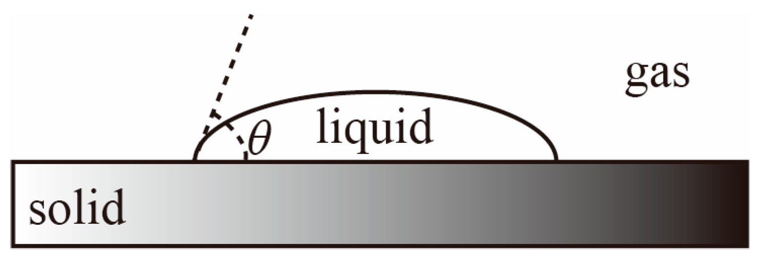
The droplet morphology on the solid surface is shown in
Figure 4.
θ denotes the wetting angle between the liquid–gas interface and the solid–liquid interface. In other words, the tangent line to the liquid–gas interface is drawn over the contact point of the solid–liquid–gas interface, and the angle between this tangent line and the solid–liquid interface.
The wetting angle
θ = 0° indicates that the liquid can completely spread on the solid surface, forming a liquid film, showing complete wettability of the liquid on the solid surface. A wetting angle within the range of 0° <
θ < 90° indicates that droplets on the solid surface can partially spread, forming a relatively flat droplet, and the droplets can partially wet the solid surface, demonstrating good interfacial stability between the two phases. A wetting angle within the range of 90° <
θ < 180° indicates that droplets on the solid surface almost do not spread at all, forming a highly protruding “sitting” droplet, with weak interfacial bonding stability [
25]. The wetting angle is between 90° and 180°, indicating that the droplet almost does not spread on the solid surface, forming a highly protruding “sitting” droplet, and the interfacial bonding stability is weak.
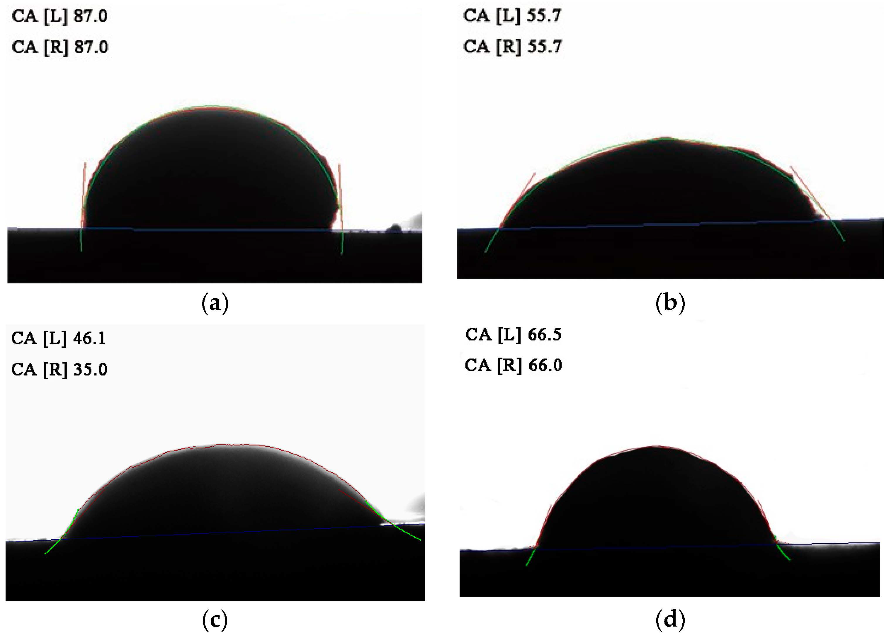
The detailed procedure for wetting angle measurement is as follows: Firstly, Ag, Ni, and Nb powders were weighed quantitatively. The total mass of the substrate material was 3 g. If the undoped Ni phase was used as the substrate, 3 g of Ni powder was weighed. If the Nb-containing Ni phase was used as the substrate, 2.7 g of Ni powder and 0.3 g of Nb powder were weighed. Additionally, 0.3 g of Ag powder was weighed. Subsequently, the weighed substrate powder material was placed into the planetary ball mill for mixing. Onyx balls were used as the ball material, and anhydrous ethanol was added to the grinding jar. After drying, the substrate material was pressed into a sheet. Since the total mass of the powder was only 3 g, a pressure of 5 MPa was applied to prevent the substrate from cracking, and the holding time was set to 5 min. Subsequently, the pressed Ni phase substrate was placed in a vacuum tube furnace for sintering. The temperature was set to 1100 °C, and the holding time was set to 5 min. The sintering temperature was set at 1100 °C, and the holding time was set to 60 min. Afterwards, Ag powder was uniformly placed on the Ni plate and sintered. This process caused the Ag powder to melt into molten droplets, ensuring that it could naturally spread on the Ni phase substrate. The melting point of Ag was 961.93 °C. To ensure complete melting, the sintering furnace temperature was set to 1050 °C, and the holding time was set to 30 min. Afterwards, the wettability angle was measured, and the images were captured by a computer to determine the wetting angle of the Ag powder. A computer was used to intercept the images and measure the wetting angle on both sides.
Figure 5a–d show the wetting angle measurements of AgNi contact materials before and after doping, respectively. As can be seen from
Figure 5, after doping, the diffusion between Ag and the substrate is enhanced, the penetration is evident, and the wettability is improved. The wetting angle of AgNi before and after doping is less than 90°. The wetting angle of undoped AgNi contact material is close to 90°, indicating poor wettability between Ag and Ni. After doping, the wetting angles are reduced. The wetting angle of Nb(4.55)-doped AgNi contact material is the smallest, followed by the wetting angle of Nb(2.29)-doped AgNi contact material, and finally the wetting angle of Nb(6.77). The wettability ranking aligns with the ranking of interfacial bond strength.
4.3. Electrical Contact Experiments
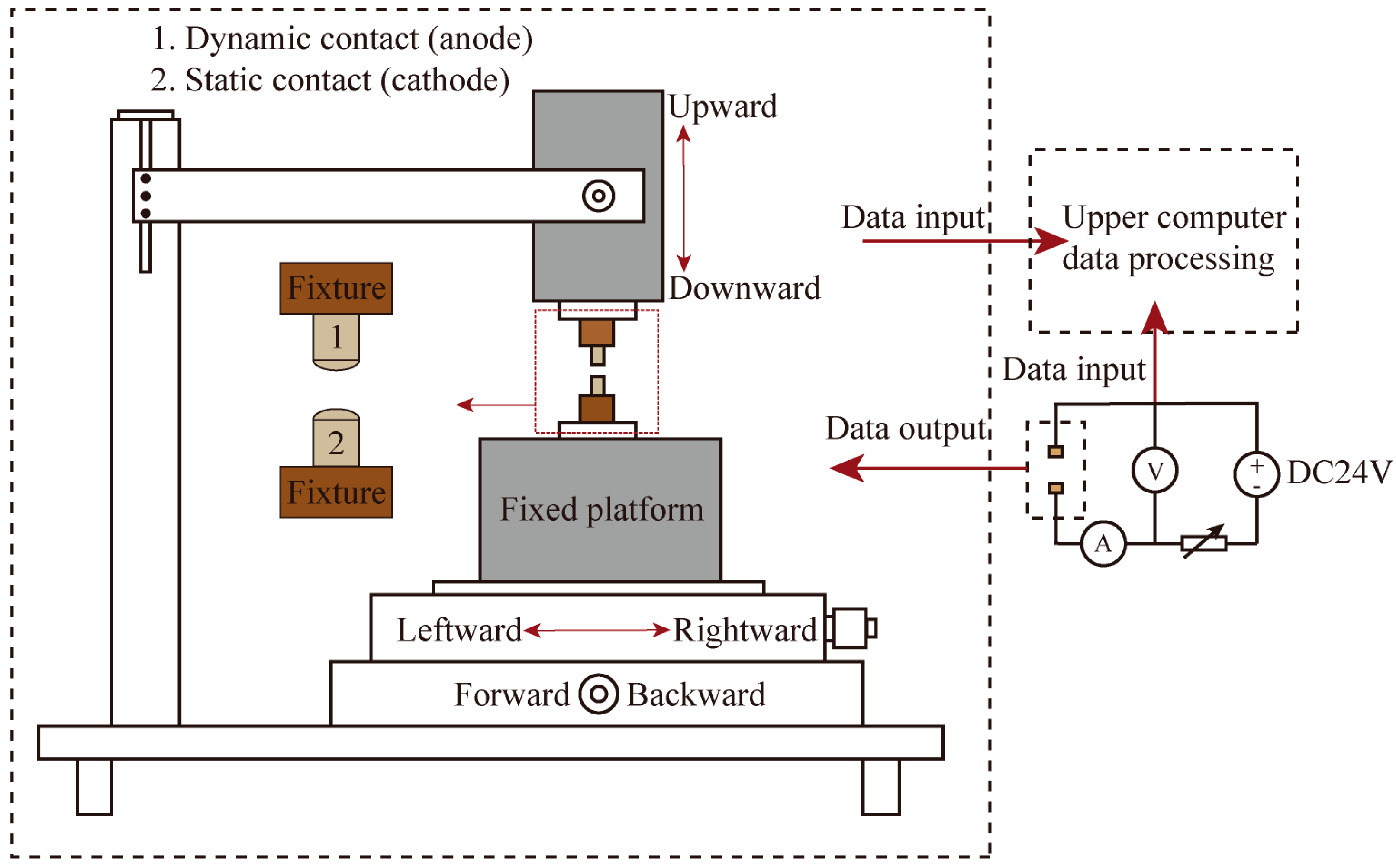
In this paper, the JF04D electrical contact material performance test system was utilized to conduct electrical contact simulation experiments, enabling direct measurement of the electrical contact parameters of each contact. A schematic diagram of the JF04D electrical contact material test system is illustrated in
Figure 6. The test system’s start-up protection voltage was set at ±40 V, with a DC voltage of 24 V, an experimental current of 15 A, an operational frequency between the contacts of 60 times per minute, and a contact pressure set at 86 cN. Due to the experimental use of DC voltage and current, the AC arc “zero rest” phenomenon is absent. This absence leads to more serious contact erosion. Additionally, the JF04D electrical contact material test system does not have an arc-extinguishing device. Therefore, considering these factors, the number of electrical contacts was set at 10,000 times, with an average value being taken every 100 times as one data point. The JF04D electric contact material testing system did not have an arc-extinguishing device installed. Therefore, with the electric contact frequency set at 10,000 times, the average value for each cycle was established with 100 times being one data point. Electrical contact performance testing involves using a test stand to simulate the separation action of the moving and static contacts multiple times to replicate the process of disconnecting and closing actions. At the moment of separation, a high-temperature arc is generated. At this point, the energy of the arc near the anode of the moving contact is higher than the energy of the arc near the cathode of the static contact. The ablation effect of the arc at the anode of the moving contact is more severe. Therefore, Nb-doped AgNi anode contact material was mounted on the dynamic contact, and undoped AgNi cathode contact material was mounted on the static contact to observe the impact of varying levels of Nb doping on the arc erosion resistance of the AgNi electrical contact material.
Arc energy, arc duration, and welding force are important parameters for assessing the performance of contact materials [
26]. During the electrical contact performance test process, the contact material experiences a gradual decrease in dynamic and static contact pressure upon separation. Consequently, the actual contact surface between the contacts diminishes, leading to an increase in current density at the contact point. This increase results in a rapid temperature rise, potentially reaching the melting point of the metal or even the boiling point of the contacts. This can generate an arc between the contacts, causing arc erosion, material transfer, and other physical and chemical processes in the electrical contact material [
27]. An arc is a physical phenomenon due to electrical contact during performance experiments. The degree of arc erosion becomes more serious with the increase in arc energy, while the arc energy increases with the lengthening of the arc duration. During the repetitive breaking and closing process of the electric contact surface, a high-temperature arc is generated, leading to localized melting. The severity of the contact is determined by the stability of the welding after the melting of the contact. The force required to separate the welding contact at its smallest breaking point is referred to as the fusion welding force. When the breaking force is less than the fusion welding force, the contact cannot undergo normal breaking, contact welding, or electrical function failure, resulting in a smaller electrical contact welding force being considered better for anti-melting welding performance with the contact material.
Figure 7,
Figure 8 and
Figure 9 display the relationship curves between arc ignition energy, arc ignition time, welding force, and the number of operations with varying Nb doping contents, respectively.
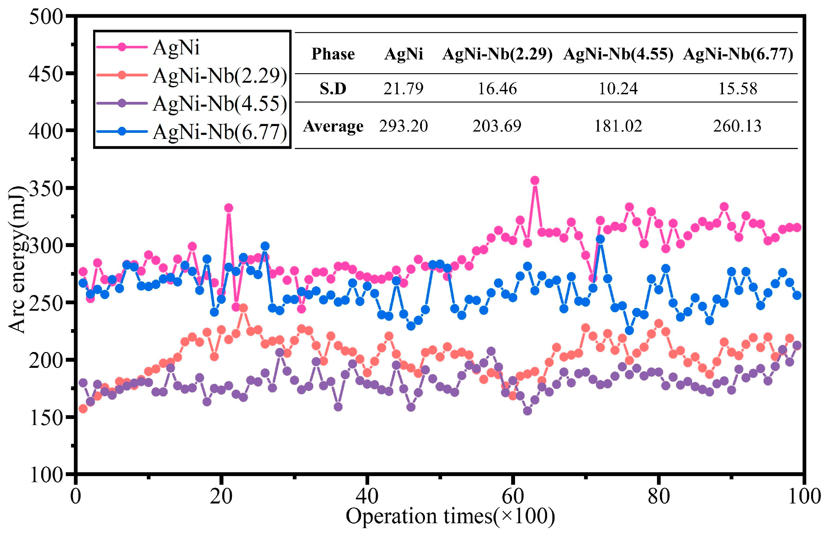
As shown in
Figure 7, doping with Nb effectively reduces the arc energy of AgNi contact materials. With an increase in Nb content, the average arc energy of the electrical contact materials decreased by 30.53%, 38.26%, and 11.28%, respectively. This enhancement improves stability, and the distribution of waveform curves ranges from 150 mJ to 310 mJ. The arc energy does not show a significant increase with the increase in the number of passes when doped with Nb. The degree of improvement in performance with the increase in Nb content showed a trend of initially increasing and then decreasing. Among them, the Nb(4.55)-doped arc energy decreased significantly, while the Nb(6.77)-doped arc energy showed a significant difference with the undoped material after only about 5000 passes. In addition, after Nb(4.55) doping, the arc energy decreased significantly after about 5700 cycles, indicating that with the increase in the number of operations, the high temperature generated by the arc leads to the melting of the contact surface of the fine burrs. The surface smoothness was slightly improved, and the arc energy then declined. With Nb(6.77) doping, until about 7200 cycles, the arc energy did not show a significant downward trend. By 7500 cycles, the arc energy had continued to rise. The number continued to rise to around 7500 times. The above phenomenon demonstrates that, with the further increase in Nb content, the decrease in the basal elements, especially Ni content, weakened the dissolution–precipitation effect. This led to the formation of many Nb-Ni alloys and other precipitates, further diminishing the impact of the dissolution–precipitation effect. Simultaneously, it resulted in material inhomogeneity, intensified arcing, and serious erosion of the surface morphology.
Arc duration is the time from the start of combustion to extinguishment, and it is correlated with arc energy. Generally, a higher arc energy results in longer arc durations and more pronounced erosion effects on the contact surface.
Figure 8 shows that the impact of varying Nb doping content on arc duration is similar to its effect on arc energy. However, the changes in arc duration are more pronounced than those in arc energy. Specifically, Nb(2.29) doping results in a slight delay in the decline and subsequent rise in arc duration compared to other doping materials.
As can be seen from
Figure 9, with the increase in Nb content, the fusion welding force shows a tendency to decrease first and then increase, but the improvement in stability is not significant. Under the high-temperature arc, the temperature of the arc root area increases instantly. Ni particles are rapidly dissolved in the Ag droplets in the molten state. As the arc extinguishes, the temperature decreases, causing the Ni dissolved in the Ag solution to precipitate. This process easily forms an enriched area on the contact surface, leading to a sharp rise in contact temperature. Consequently, the metal melting pool expands, resulting in an increased actual fusion welding area, thereby enhancing the fusion welding force [
28]. During the experimental process, the material between the AgNi contacts is transferred due to the arc’s action, leading to variations in contact pressure on the contact surface. These variations subsequently influence the fusion welding force. Nb can be utilized to achieve a uniform distribution of precipitates by promoting precipitation and regulating the cooling rate. This approach can also manage the arc in specific local areas where it initiates ignition, enhancing the resistance to melting and welding. Excessive amounts of Nb can enhance the strengthening effect of material grain boundaries, hindering their movement and deformation. This, in turn, increases the resistance to deformation and thermal deformation during fusion welding, ultimately requiring a higher fusion welding force.
In addition, by comparing similar research papers, we found that the arc energy of undoped AgNi(10) electrical contact materials prepared by the high-energy ball milling method decreased by 60.9% compared to the conventional mixing method [
29]. The arc energy of AgNi doped with 2.29% and 4.55% Nb decreased by 2.5% and 13.4%, respectively, compared to the same material doped with 1.38% Cu. In contrast, the arc ignition energy of the material doped with 6.77% Nb increased by 24.4%. The melting force of AgNi contact materials with three different levels of Nb doping decreased by 44.4%, 47.6%, and 39.2%, respectively, compared to 1.38% Cu doping [
30]. The superiority of Nb-doped AgNi contact material has thus been proven.
In summary, the analysis of AgNi electrical contact materials regarding arc energy, arc duration, and welding force indicates that Nb doping can effectively enhance the degree of arc erosion of AgNi electrical contact materials and the degree of material transfer. As the Nb content increases, the degree of arc erosion of the contact initially decreases and then increases, aligning with the simulation results.


