Article

Effects of Process Parameters on Microstructure and Wear Resistance of Laser Cladding A-100 Ultra-High-Strength Steel Coatings

1
College of Mechanical Engineering, Nanjing Vocational University of Industry Technology (NJUIT), Nanjing 210023, China
2
College of Materials Science and Technology, Nanjing University of Aeronautics and Astronautics (NUAA), Nanjing 210016, China
3
Jiangsu Province Precision Manufacturing Engineering and Technology Research Center, Nanjing 210023, China
4
Avic General Huanan Aircraft Industry Co., Ltd., Zhuhai 519040, China
5
Fengze Intelligent Equipment Co., Ltd., Hengshui 053000, China
6
Arkema-ArrMaz, R&D Mining Lab, Mulberry, FL 33860, USA
*
Authors to whom correspondence should be addressed.
Coatings 2024, 14(6), 669; https://doi.org/10.3390/coatings14060669
Submission received: 11 April 2024 / Revised: 19 May 2024 / Accepted: 21 May 2024 / Published: 25 May 2024
(This article belongs to the Section Laser Coatings)

Abstract

:
To improve the hardness and wear resistance of mild steel, A-100 ultra-high-strength steel cladding coatings were prepared on the surface of mild steel by laser cladding. In this study, the effects of laser cladding process parameters on the forming quality, phase composition, microstructure, microhardness and wear resistance of the A-100 ultra-high-strength steel cladding coatings were researched. The results show that the main phase of the coating is martensite and a small amount of austenite. The microstructures of the upper part of the cladding coatings are mainly equiaxed grains, while those of the lower part are mainly columnar grains. With an increase in laser specific energy, the microstructures of the cladding coatings become coarse. When the laser specific energy is 70.8 J/mm2, the microhardness of the cladding coating is the highest, and the maximum average microhardness of the cladding coatings is 548.3 HV. When the laser specific energy is low, the wear of the cladding coatings is mainly pitting, while when the laser specific energy is high, the wear type of the cladding coatings is mainly adhesive wear. Moreover, the microhardness and wear resistance of the cladding coatings are reduced if the laser specific energy is too high.

1. Introduction

Metal materials are the most widely used materials in industrial and agricultural production. Among many metal materials, mild steel is widely used in automobile, ship and machinery manufacturing because of its advantages of good formability, excellent plasticity and higher cost performance [1,2,3]. However, mild steel also has some inherent weaknesses, such as low hardness and poor wear resistance, which cause a reduction in the suitable life of mild steel [4]. Moreover, with the continuous improvement of mechanical equipment performance requirements, the mechanical properties of materials required for manufacturing are also constantly improving, requiring the surface properties of mild steel to be significantly improved.
Improving the surface properties of mild steel by surface modification is an important means to extend the service life of mild steel [5,6]. Among the many surface modification technologies, laser cladding technology has become one of the most widely used [7,8]. Compared with coatings from other surface modification technologies, the thickness of the laser cladding coating can reach 1–2 mm, and the laser cladding coating has better densification, smaller grains and more reliable bonding ability with the substrate [9,10]. Hence, laser cladding technology has become an ideal technology to improve the surface properties of mild steel.
The effect of surface modification of mild steel not only depends on the process used but also is closely related to the surface modification material. For laser cladding technology, the ideal cladding material should have the following characteristics: good wettability and similar melting point with the substrate, good crack resistance and wear resistance [11]. A-100 ultra-high-strength steel (AerMet 100, AMS 6532, USA, 2018) is a high-strength martensitic alloy steel with ultra-high fracture toughness and hardness [12]. A-100 ultra-high-strength steel is alloyed with 15% Co, 11% Ni, 3% Cr and 1.5% Mo, and it has good wettability with mild steel. A-100 ultra-high-strength steel is a candidate material for improving the surface mechanical properties of mild steel.
Electric arc surfacing is an important technology for the surface modification of materials [13]. However, due to the high dilution rate of electric arc surfacing, the mechanical properties of the surfacing layer are reduced. Laser cladding is a process of rapid melting and solidification of cladding materials. Compared with electric arc surfacing, the dilution rate of laser cladding coating is lower. Due to rapid melting and solidification, the residual stress of the cladding coating is large [14]. Moreover, A-100 ultra-high-strength steel is martensitic alloy steel, and the alloying element content is as high as about 30%, which also increases the tendency of A-100 ultra-high-strength steel cladding coatings to crack. The inherent physical properties of A-100 ultra-high-strength steel cannot be changed. To reduce the cracking tendency of cladding coatings, it is necessary to reduce their residual stress. In the process of laser cladding, the solidification rate of the molten pool is related to the magnitude of residual stress and closely related to the parameters of the laser cladding process [15]. Therefore, optimizing the cladding coating manufacturing process parameters is beneficial to reducing the residual stress of the cladding coating. Moreover, the surface forming quality, geometrical characteristics, dilution degree, microstructure and properties of the cladding coating are also affected by the laser cladding process parameters [16]. Hence, it is necessary to study the laser cladding process parameters of A-100 ultra-high-strength steel.
Bo Zhang et al. [17] researched and optimized the process parameters to improve the wear resistance of 15-5PH steel cladding coatings. With an increase in laser power, the dilution rate of the coating increases. A cladding coating with a high dilution rate has obvious cracking sensitivity. As the laser power increases, martensitic hardening and carbide precipitation occur, which leads to an increase in the microhardness of the cladding coating. Zelin Xu et al. [18] analyzed the influence of process parameters on the microstructure and high-temperature oxidation properties of IN718 laser cladding coatings. The results showed that the laser power and scanning speed have an influence on the eutectic precipitation, and the eutectic precipitation is positively correlated with the mass gain of the coating. Sirui Yang et al. [19] performed multi-objective parameter optimization for laser cladding of IN718 cladding coatings. The validation experiments on single-pass and multi-pass cladding coatings were carried out with the optimal parameters, and it was proved that the process parameters were closely related to the quality of cladding coatings. Zipeng Su et al. [20] studied the influence of process parameters on the microstructure and friction properties of laser cladding Ni60A/Cr3C2 coatings. The influence of process parameters on the temperature field distribution, microstructure and wear resistance of laser cladding Ni60A/Cr3C2 composite coatings was studied by combining simulations and experiments. When the laser power was 1800 W, the scanning speed was 5 mm/s, and the powder feeding speed was 8 g/min, the performance of Ni60A/Cr3C2 composite coating was the best, the coating friction process was smoother, and the friction coefficient was lower. Kefeng Lu et al. [21] reported the preparation of high-entropy alloy coatings with different components of microstructure, corrosion resistance and wear resistance by laser cladding. They found that the microstructure and properties of HEA coatings are significantly affected by different process parameters, and the optimization of process parameters plays an important role in improving the coating quality. By analyzing the results from these researchers, it can be seen that the laser cladding process parameters have a broad influence on cladding coatings, and the influence is very obvious. By optimizing the process parameters of laser cladding, the microstructure of cladding coatings can be well regulated, the defects can be reduced, and the performance can be improved.
Laser cladding process parameters directly affect the existence time of the molten pool and the melting process, and they also affect the surface forming, microstructure, microhardness and wear resistance of the laser cladding. In this work, A-100 ultra-high-strength steel coatings were prepared on the surface of mild steel Q235 (GB/T 700-2006) by laser cladding technology. In this study, the influence mechanism of laser cladding parameters on the microstructure and mechanical properties of A-100 ultra-high-strength steel cladding coatings was examined to obtain the best laser cladding parameters. Research on the technology for laser cladding A-100 ultra-high-strength steel coatings onto mild steel surfaces can provide a technical parameter reference for engineering applications of laser cladding A-100 ultra-high-strength steel coatings.

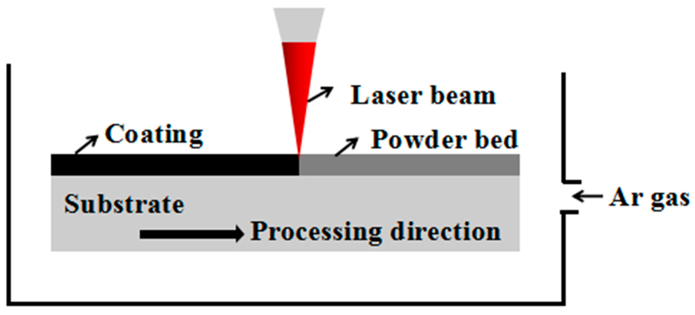
2. Materials and Methods

Mild steel Q235 (BG/T 700-2006) with a size of 40 cm × 20 cm × 10 cm was selected as the base material for laser cladding. The mild steel was a hot-rolled sheet produced by Guangxi Liuzhou Iron and Steel Group Co., Ltd., (Liuzhou, China). The chemical composition of mild steel Q235 according to standard GB/T 700-2006 is shown in Table 1. Before the laser cladding experiment, the mild steel substrate was polished with metallographic sandpaper to remove surface rust. The polished substrate was put into an ultrasonic cleaning machine, and the abrasive dust on the substrate was cleaned with deionized water as the cleaning medium. After cleaning, the substrates were put into a drying oven and dried at 110 ℃ for 2 h. This ensured that the substrate was dry to avoid the formation of pores in the laser cladding coating process.
A-100 (AerMet ® 100, AMS 6532) ultra-high-strength steel powder was selected as the laser cladding powder material. The A-100 ultra-high-strength steel powder was real air-atomized powder produced by Anhui Shengsai Manufacturing Technology Co., Ltd. (Anqing, China). The A-100 ultra-high-strength steel powder particles were spherical or nearly spherical, and the particle diameter was generally about 60 μm. The element composition of the A-100 ultra-high-strength steel powder was tested by an EDS (tested two different powder particles), and the test results are shown in Table 2. A-100 ultra-high-strength steel powder was laid on the surface of the substrate with the help of a self-made mold to ensure a uniform powder thickness, and the thickness of the powder bed was 1 mm.
A schematic diagram of the laser cladding process is shown in Figure 1. The laser cladding experiment was carried out in a self-made semi-closed box with a size of 20 cm × 15 cm × 8 cm. Before laser cladding, protective argon gas was first filled into the box, with a flow rate of 15 L/min and inflation time of 3 min, so that the sample to be cladded was protected by argon. We selected a laser power of 1700–2300 W, a scanning speed of 3–9 mm/s, and a laser beam spot diameter of 4 mm. The laser cladding process parameters and laser specific energy (Es) are shown in Table 3.
The diameter of the fixed circular spot was 4 mm for laser cladding. In the process of laser cladding, argon gas filled the box to protect the cladding process. After the laser cladding was finished, the protective gas was turned off until the cladding coating dropped to room temperature, to avoid the cladding coating being oxidized by oxygen. The cladding coating was formed by melting, chemical metallurgical reaction, cooling and solidification after laser irradiation.
The phase composition of the laser cladding sample was analyzed by an X ‘PERT Pro MPD X-ray diffractometer (XRD) produced by Nalytical, the Netherlands. The X-ray scanning method was continuous scanning, and the scanning angle was 2θ = 20–90°.
After the cross section of the selected coating sample was hot-inlaid (inlaid temperature 140 °C, holding time 5 min), the inlaid sample was polished with 400#, 600#, 800#, 1000#, 1500# and 2000# metallographic sandpaper in turn. Then, the polished sample was polished with a diamond grinding paste with a particle size of 5 μm. After the polishing, the sample was cleaned and dried with anhydrous ethanol, and then the sample was etched with 4% nitrate alcohol solution as the metallographic etching reagent; the etching time was 10–15 s. After the etching of the coating samples was completed, the coating samples were cleaned with deionized water and anhydrous ethanol successively to wash off the residual etching reagent, and then the coating samples were dried for subsequent testing.
The microstructure of the cladding samples was analyzed by optical microscopy (OM, Sunny Optical Technology Co., Ltd., Ningbo, China). The microstructure of the cladding samples was observed by scanning electron microscopy (SEM, VEGA Compact, Tescan, Brno, Czechia). A BRUKER Quanta x400 and a QUANTAX FlatQUAD energy-dispersive spectrometer (EDS) were used to analyze and test the composition and distribution of chemical elements in the selected microzone and the selected route of the cladding coatings.
An HXS-1000 A-type digital liquid crystal intelligent microhardness tester produced by Shanghai Haowei optoelectronic Technology Co., Ltd. (Shanghai, China) was selected as the equipment for testing the cross-sectional microhardness distribution of cladding samples. The microhardness test started from the top of the cladding layer along a straight line to the matrix hardness test. The load was 100 g and the holding time was 15 s.
The tribological properties were tested by a developed ring block friction and wear testing machine. Bearing steel was used as the friction pair material in the friction wear test of cladding samples; the outer diameter of the friction ring was 50 mm and the inner diameter was 45 mm. The friction block was a cladding sample with a size of 1 × 1 × 1 cm3. During the experiment, the friction ring was installed at the end of the rotating shaft, and the friction block was installed at the bottom of the loading mechanism. The friction between the rings was detected by a tension pressure sensor. During the experiment, the ring block friction pair was first installed, the speed of the testing machine was controlled to 100 r/min, the load was controlled to 10 N by applying the loading weight, and the test time was 300 s. After the friction and wear test, the friction ring and friction block were cleaned by ultrasonic cleaning with petroleum ether and anhydrous ethanol, respectively, and the mass difference of friction samples before and after the weighing test was analyzed by a METTler Me204 analytical balance (Switzerland).

3. Results and Discussion

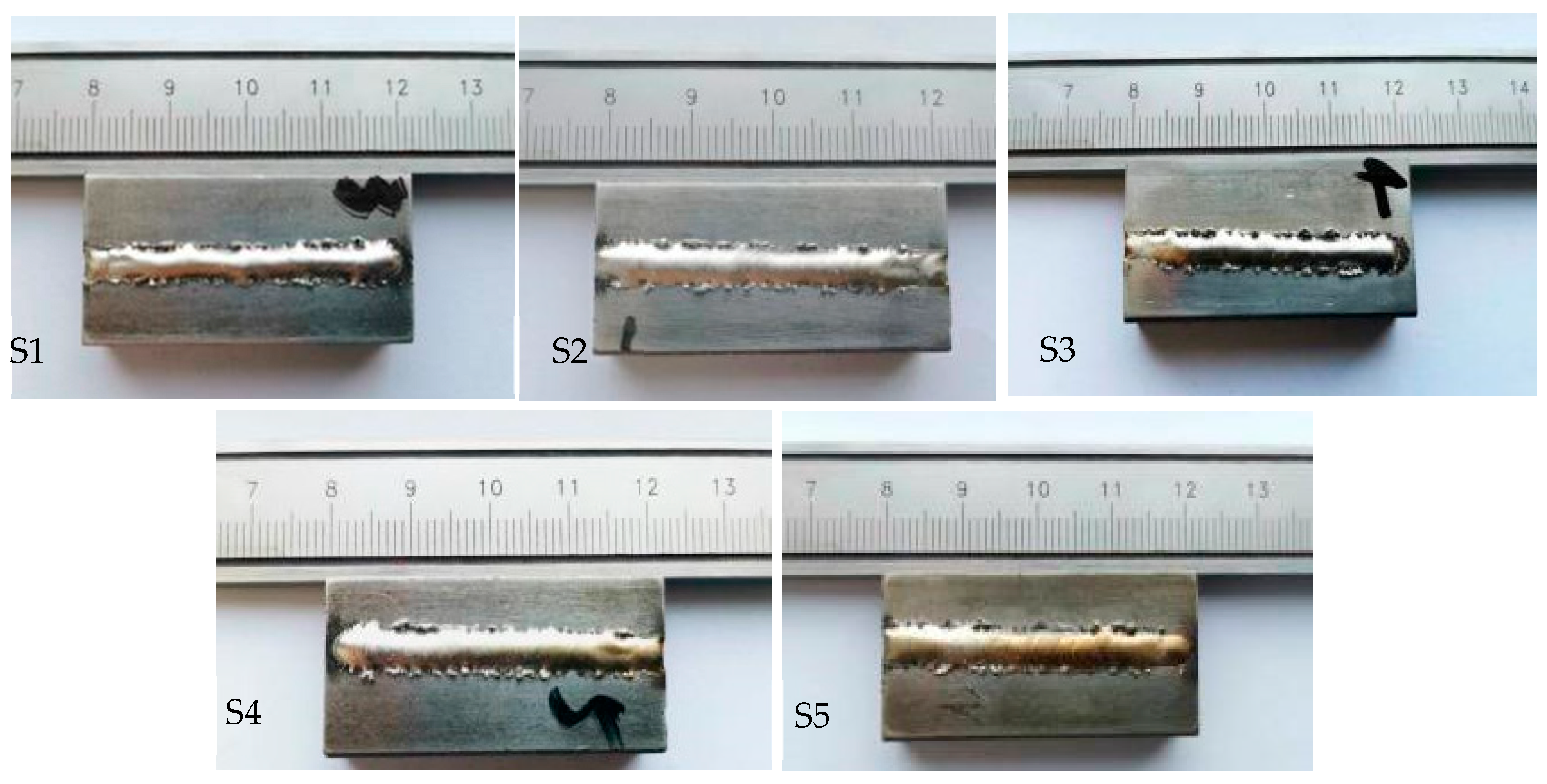
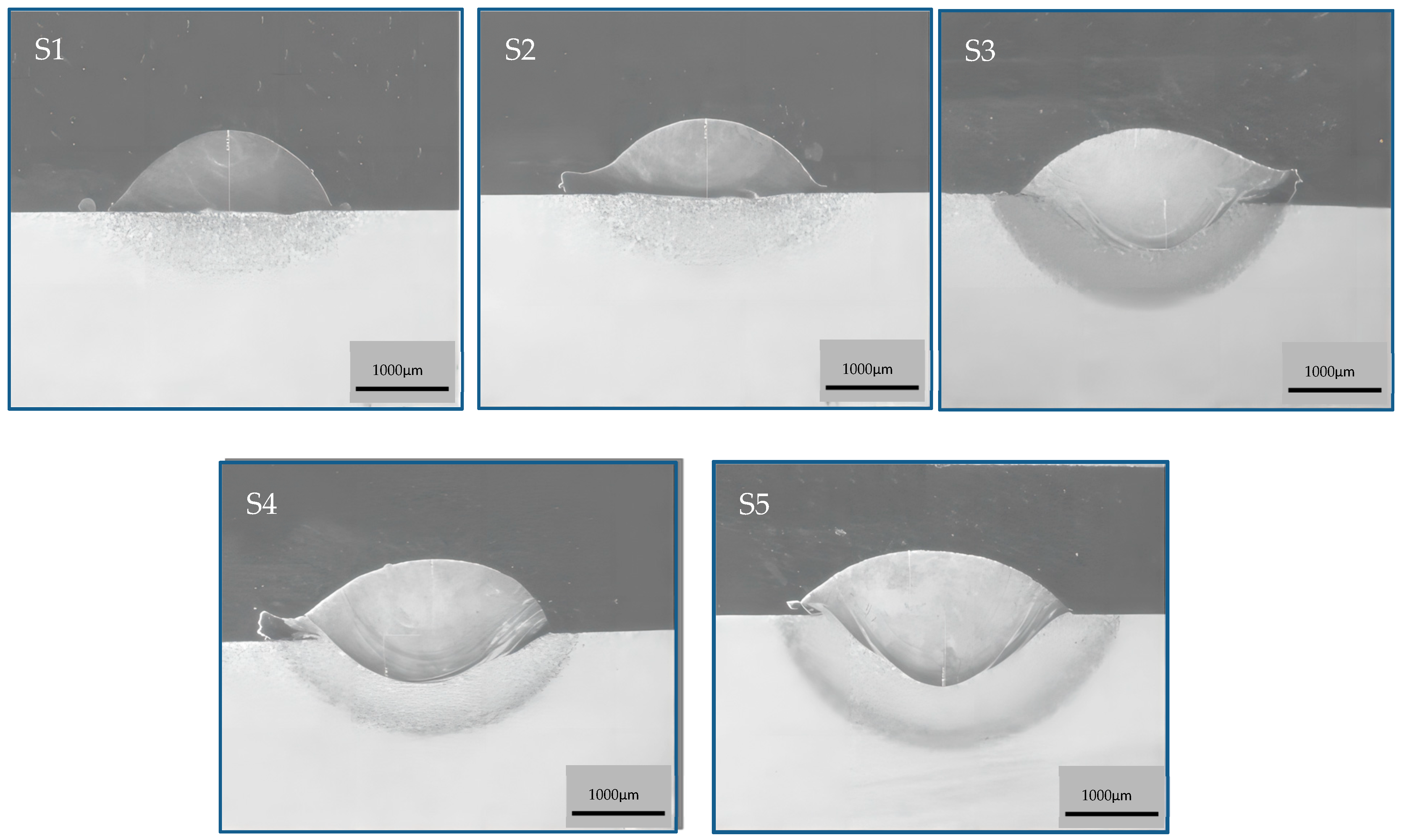
3.1. Macroscopic Morphologies of A-100 Ultra-High-Strength Steel Cladding Coatings

The macroscopic morphologies of laser cladding coatings of A-100 ultra-high-strength steel are shown in Figure 2. It can be seen from the figure that the surface of the laser cladding coatings was bright and no obvious oxidation had occurred. The cladding coatings were well formed, the surface was continuous and smooth, and there were no obvious defects such as spheroidization, porosity or cracks.
The cross-sectional morphology of the A-100 ultra-high-strength steel cladding coatings is exhibited in Figure 3. The cladding coatings presented an upward arch. The bonding between the cladding coating and the substrate was good, and there was no cracking phenomenon between the cladding coating and the substrate. With an increase in the laser’s specific energy (S1→S5), the penetration depth and dilution rate of the cladding coatings increased. There were no pores or microscopic cracks inside the cladding coatings.

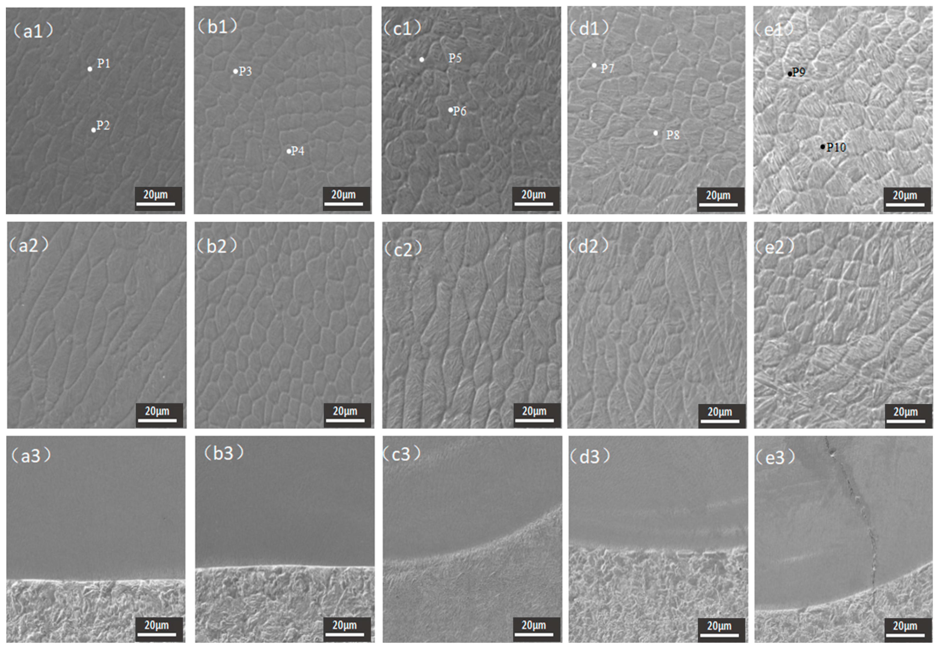
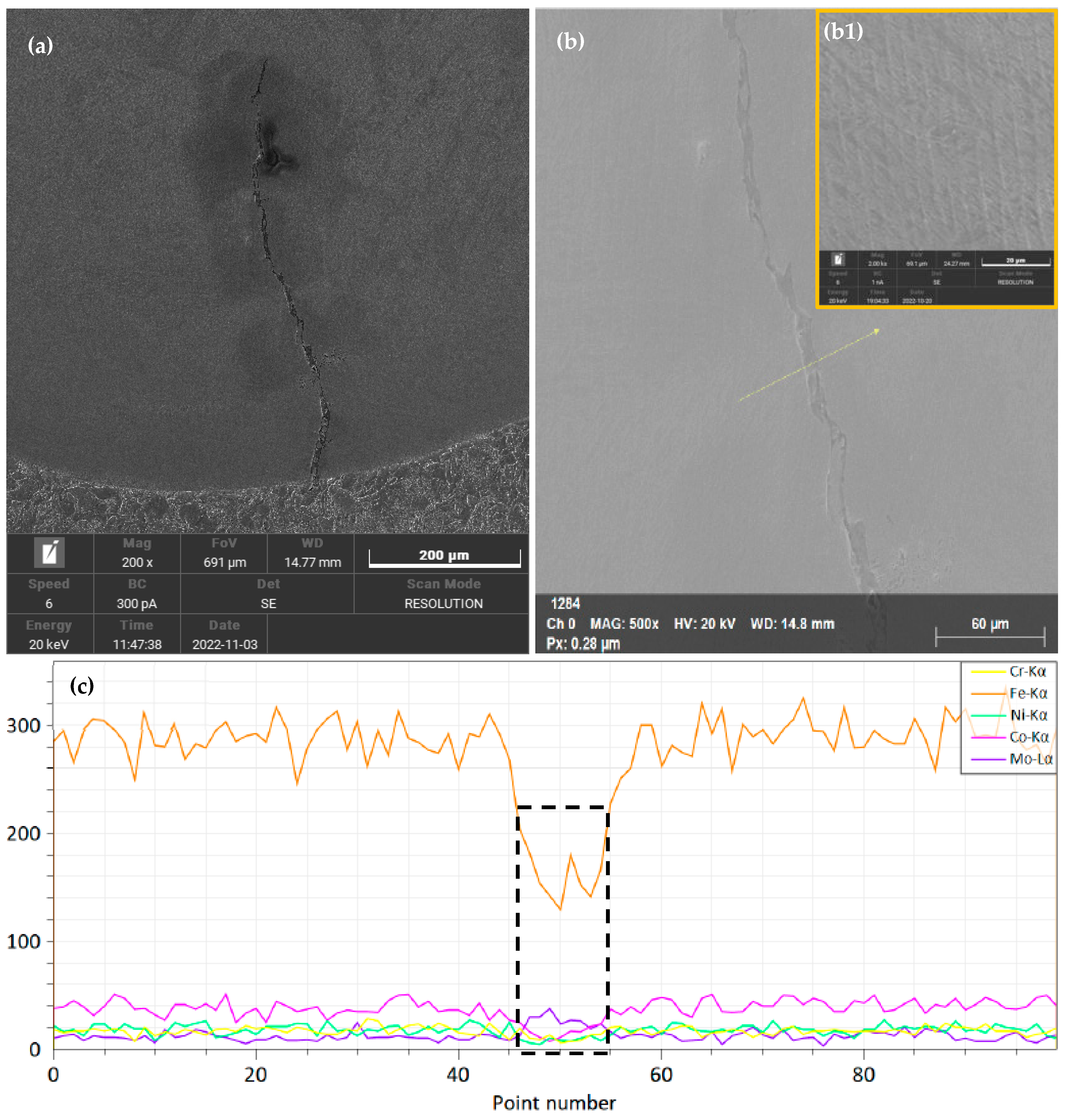
3.2. Phase Composition and Microstructure of A-100 Ultra-High-Strength Steel Cladding Coatings

The XRD phase analysis results of A-100 ultra-high-strength steel cladding coatings are shown in Figure 4. The cladding coatings prepared with different process parameters were mainly composed of martensite and austenite. Different laser cladding processes had no obvious effect on the phase composition of the cladding coatings.
The microstructures of the A-100 powder cladding coatings are displayed in Figure 5. A-100 ultra-high-strength steel is mainly composed of plate and strip martensite [22]. The different parts of A-100 ultra-high-strength steel present obviously different microstructures: the upper part of the laser cladding coating presents equiaxed grains and the lower part presents columnar grains, which is mainly related to the different solidification conditions of the upper part and the lower part of the cladding coating. Solidification of the molten pool begins at the interface between the cladding coating and substrate. When the lower part of the cladding coating begins to solidify, the temperature gradient is relatively large, the solidification rate is relatively small, and the grain growth is sufficient, resulting in mainly columnar grains. When the upper part of the cladding coating solidifies, the temperature gradient decreases, the solidification rate increases, and the grains do not have enough time to grow after nucleation, so the grains are mainly equiaxed. The hardness value of A-100 ultra-high-strength steel is 600–610 HV. However, the hardness value of the laser cladding layer of A-100 ultra-high-strength steel is lower than 600 HV. Compared with the microstructure of A-100 ultra-high-strength steel (continuous martensite structure), the microstructures of A-100 ultra-high-strength steel cladding coatings have better plasticity and toughness.
It can be seen from Figure 5 that when the laser specific energy was 166.7 J/mm2 (S5 cladding coating), a crack appeared at the fusion line between the lower part of the cladding coating and the substrate. In order to further study the causes of the crack, overall and local high-magnification images of the crack and an element line scanning analysis of the crack are shown in Figure 6. The element scan analysis path follows the yellow arrow in Figure 6b. It can be seen from Figure 6a that the width of the lower part of the crack was larger than that of the upper part. Therefore, the crack originated from the fusion line and expanded to the upper part of the sample. Therefore, the crack was considered to be a cold crack. High laser specific energies can make the grain size of the lower part of the S5 cladding sample coarse (as shown in Figure 6(b1)). During the solidification process, the cladding coating is subjected to tensile stress from the substrate material. High laser specific energies can increase the heat-affected zone and hardenability of the substrate material, so that the tensile stress of the cladding coating from the substrate material also increases, and the crack resistance of the coarse microstructure is poor. In addition, according to the element line scanning analysis results for the crack (as shown in Figure 6c), the variation tendency of Mo at the crack was increased, while the variation tendency of other elements was decreased; Mo improves the hardenability of steel materials, which also leads to a high hardening embrittlement crack sensitivity at the cracking site.
The EDS analysis results for elements in the A-100 powder laser cladding sample (Figure 6 shows the singular points on the grain boundary and the even-numbered points in the grain) are shown in Table 4. It can be seen from Table 4 that the content of Fe at the grain boundary was lower than that inside the grain, while the content of alloying elements at the grain boundary was higher than that inside the grain. A high content of alloying elements at grain boundaries can improve the resistance of grain boundaries to intergranular cracks. With an increase in the laser specific energy (S1→S5), the content of Fe at the grain boundary and in the grain of the cladding coating gradually increased. This is because as the laser specific energy increases, the dilution rate of the cladding coating increases, and the amount of Fe from unalloyed base Q235 steel mixed into the cladding coating increases. Too much Fe mixed into the cladding coating reduces the hardness and wear resistance of the cladding coating.

3.3. Microhardness and Wear Resistance of A-100 Ultra-High-Strength Steel Cladding Coatings

The microhardness of the A-100 ultra-high-strength steel cladding coatings is shown in Table 5. It can be seen from Table 5 that the maximum microhardness value of the cladding coatings was obtained when the laser specific energy was 70.8 J/mm2. When the laser specific energy was 166.67 J/mm2, the minimum microhardness value of the cladding coatings was obtained. Through a variance analysis of the microhardness of cladding coatings, it can be seen that when the laser specific energy was 70.8 J/mm2, the variance of the microhardness value was the largest. With an increase in the laser specific energy, the variance of the microhardness value of the cladding coatings decreased, which proves that the microhardness distribution of the cladding coatings is more uniform with increasing laser specific energy. When the laser specific energy was 55.6 J/mm2, the dilution rate of the cladding coating was low, and the main chemical composition of the cladding coating was A-100 ultra-high-strength steel, so the microhardness distribution of the cladding coating was relatively uniform. When the laser specific energy was increased to 83.3 J/mm2, the dilution rate of the coating increased, and Fe diffused into the cladding coating. However, compared with the cladding coatings with laser specific energies of 95.8 J/mm2 and 166.7 J/mm2, the existence time of the molten pool at this time was shorter, and the Fe that diffused from the substrate to the molten pool could not be adequately mixed, thus affecting the microhardness uniformity of the cladding coating.
In order to visually observe the changing trend of the microhardness of the coatings, the average value of the microhardness of the coatings is shown in Figure 7. It can be seen from Figure 7 that the microhardness of the cladding coatings generally decreased with increasing laser specific energy. With an increase in laser specific energy, the microhardness of the cladding coatings decreased because an increased amount of iron diffused into the cladding coating. Moreover, a high laser specific energy can make the molten pool exist for a longer time, and the grains can have enough time to grow. Excessive grain growth makes the microstructure of the cladding coating become coarse. According to the Hall–Petch relation, coarse grains reduce the strength and microhardness of cladding coatings [23].
The wear morphologies of the A-100 ultra-high-strength steel cladding coatings are demonstrated in Figure 8. The wear morphology pictures for the S4 cladding coating were derived from our previous research results [5]. This is because the S4 cladding coating was the same as that in ref. [5]. When the laser specific energy was low (S1 and S2 cladding coatings), the wear surfaces of the cladding coatings were relatively smooth, and small pitting pits were generated on their surfaces due to friction. When the laser specific energy was increased to 83.3 J/mm2, adhesive wear pits appeared on the wear surface of the cladding coating. With a further increase in the laser specific energy, the adhesive wear pits on the wear surfaces of the cladding coatings were more obvious, and the size of the adhesive wear pits became larger. At this time, the wear surfaces of the cladding coatings became rough and presented typical adhesive wear characteristics. Friction and wear on the cladding coating result from the process of friction between the friction pair and the coating under the action of downward pressure. During the friction process, the temperature of the cladding coating increases due to friction heat generation. If the microhardness of the cladding coating is low, the surface material of the cladding coating easily softens and deforms, resulting in cold welding between the friction pair. Under the action of the relative motion between the cladding coating and the friction pair, the surface material of the cladding coating is torn off by the friction pair, thus forming an adhesive wear pit. The lower the microhardness of the cladding coating, the easier it is for cold welding to form between the cladding coating and the friction pair, and the easier it is for adhesive wear pits to form under the action of the relative motion of the cladding coating and the friction pair. If the microhardness of the cladding coating is higher, the surface material of the cladding coating is less likely to soften and deform, that is, it is less likely to form adhesive wear pits.
Figure 9 shows the wear loss weights of the A-100 ultra-high-strength steel cladding coatings. It can be intuitively observed from the figure that with an increase in the laser specific energy, the wear loss weight of the A-100 ultra-high-strength steel cladding coatings increased and the wear resistance decreased. The surface adhesion wear of the cladding coatings was much more serious than that caused by pitting.

4. Conclusions

With laser cladding technology, ultra-high-strength steel cladding coatings with good surface forming quality were successfully prepared on the surface of mild steel. The A-100 ultra-high-strength steel cladding coatings obviously improved the hardness and wear resistance of the mild steel. The main findings of this study are as follows:
(1)
The A-100 ultra-high-strength steel cladding coatings were composed of martensite and austenite. The upper microstructure of the cladding coatings was mainly equiaxed, and the lower microstructure was mainly columnar. With an increase in laser specific energy, the microstructure of the cladding coatings generally presented the characteristics of gradual coarsening.
(2)
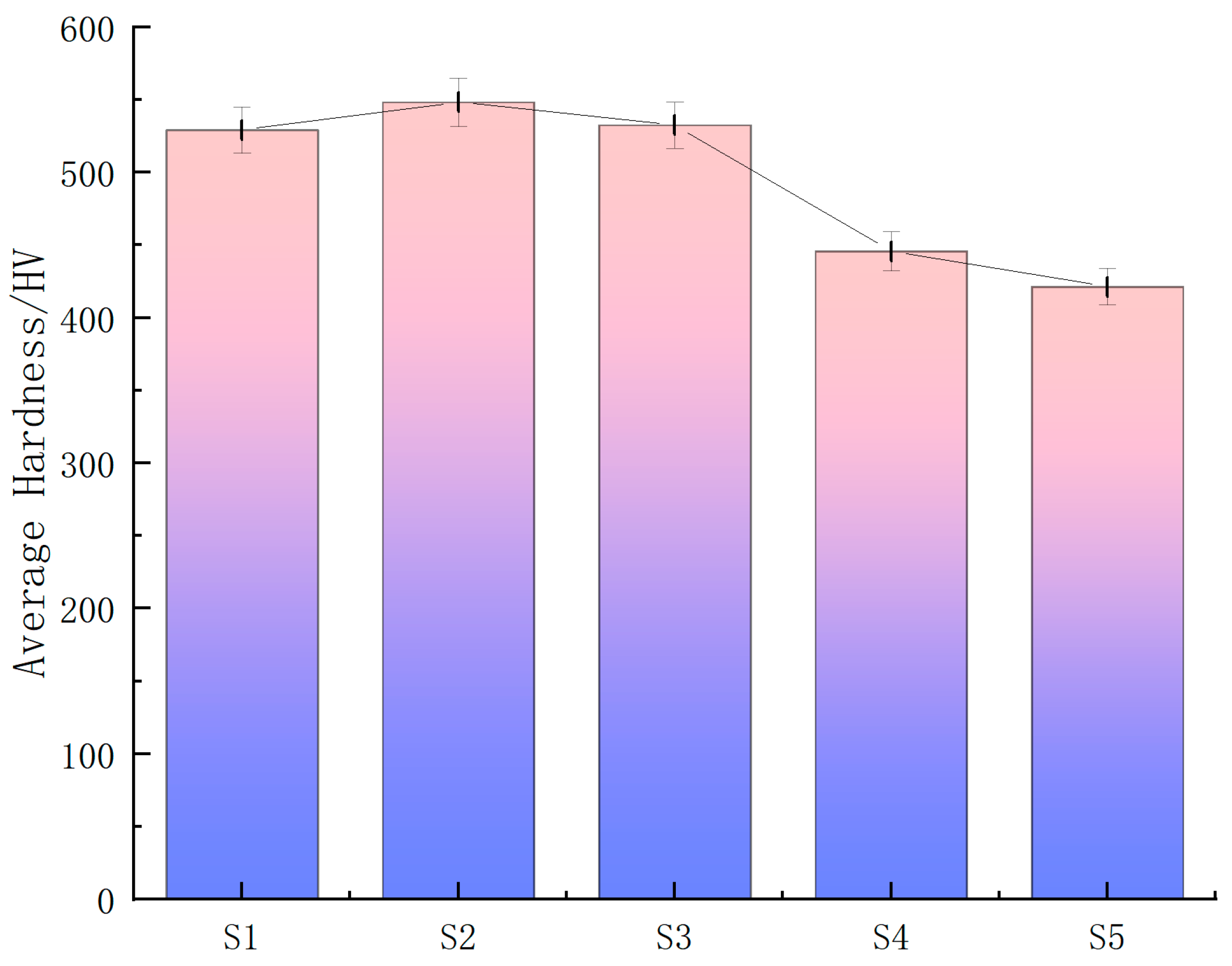
The maximum mean microhardness of the cladding coatings was 548.3 HV (S2 coating), and the minimum mean microhardness was 421.4 HV (S5 coating). When the laser specific energy was too large, the microhardness of the cladding coating decreased obviously. Although the laser specific energy for the S2 cladding coating was higher than that for the S1 cladding coating, the microstructure of the S2 cladding coating was finer.
(3)
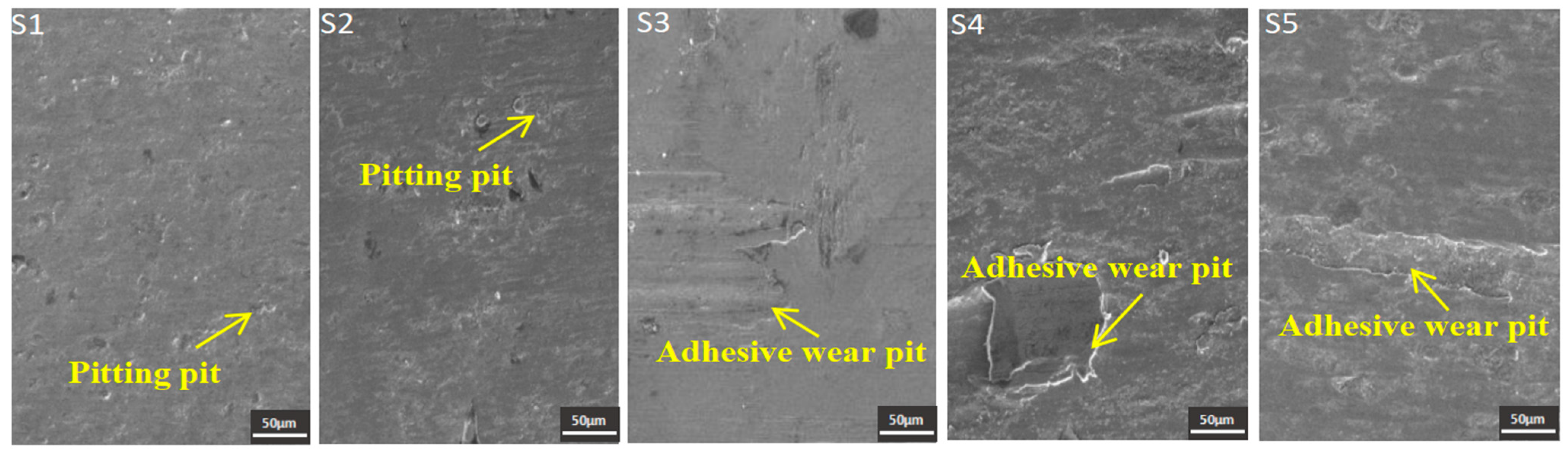
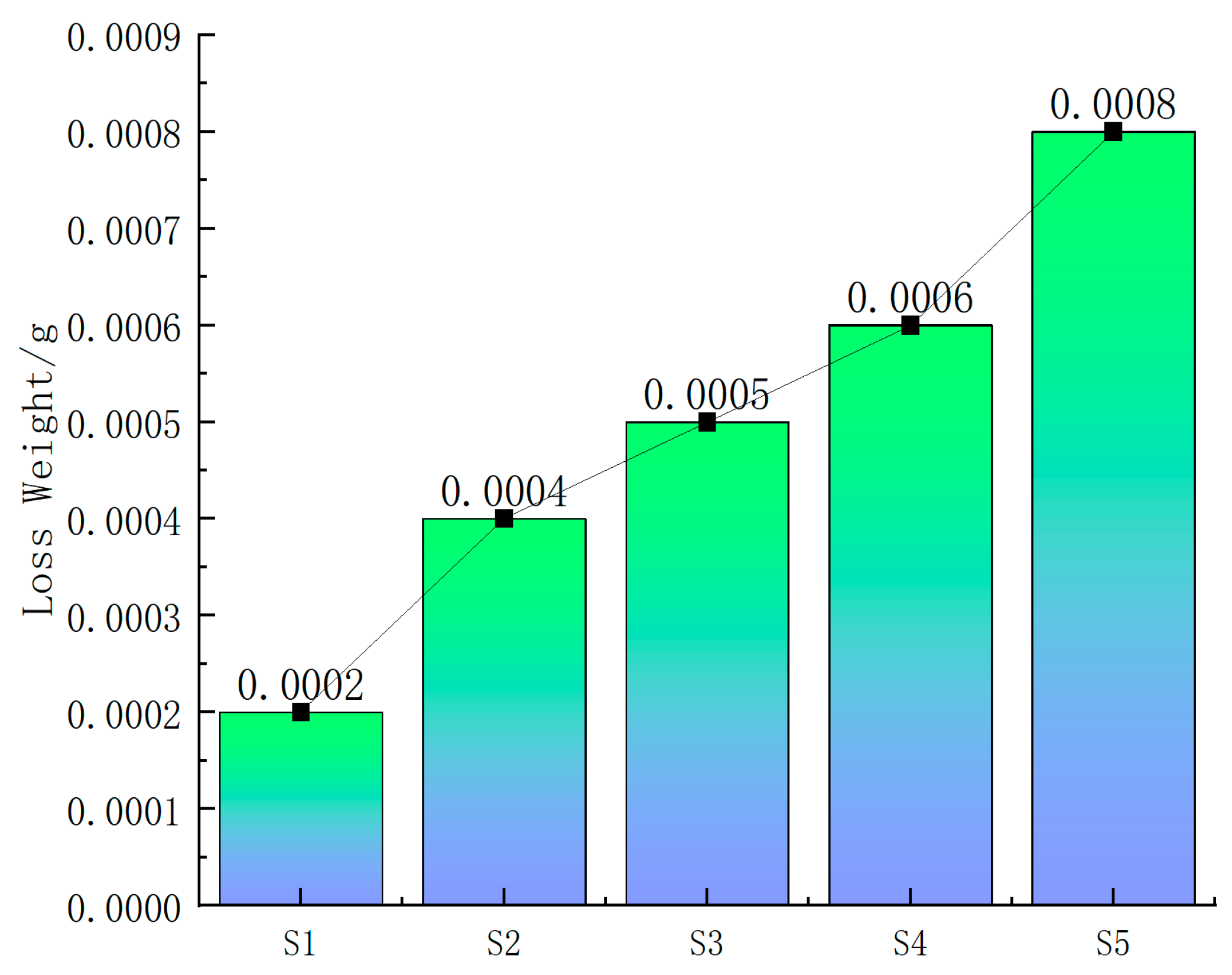
When the laser specific energy was relatively low, pitting pits mainly appeared on the wear surface of the cladding coatings (S1 and S2 coatings). When the laser specific energy was increased, adhesive wear pits mainly appeared on the wear surface of the cladding coatings. The wear loss weights caused by adhesive wear were much more serious than those caused by pitting. The wear resistance of the cladding coatings was significantly reduced by excess laser specific energy.

Author Contributions

Conceptualization, T.H. and Y.G.; Methodology, T.H. and Z.D.; Formal analysis, W.F. and X.Y.; Investigation, W.F. and X.Y.; Resources, T.H.; Data curation, Z.D. and F.C. All authors have read and agreed to the published version of the manuscript.

Funding

This research was funded by Jiangsu Province Industrial Sensing and Intelligent Manufacturing Equipment Engineering Research Center Open Fund Project (Grant Number: 201050622ZK002), Project of Talent Introduction and Scientific Research Start-Up Fund of Nanjing Vocational University of Industry Technology (Grant Number: 201050622RS005) and Jiangsu province Precision Manufacturing Engineering and Technology Research Center (JSPMET2024).

Institutional Review Board Statement

Not applicable.

Informed Consent Statement

Not applicable.

Data Availability Statement

Data are contained within the article.

Conflicts of Interest

Author Wanxi Feng was employed by the company Avic General Huanan Aircraft Industry Co., Ltd. Author Fangfang Chen was employed by the company Fengze Intelligent Equipment Co., Ltd. The remaining authors declare that the research was conducted in the absence of any commercial or financial relationships that could be construed as a potential conflict of interest. The authors declare that this study received funding from Jiangsu Province Industrial Sensing and Intelligent Manufacturing Equipment Engineering Research Center Open Fund Project; Project of Talent Introduction and Scientific Research Start-Up Fund of Nanjing Vocational University of Industry Technology; Jiangsu province Precision Manufacturing Engineering and Technology Research Center. The funder was not involved in the study design, collection, analysis, interpretation of data, the writing of this article or the decision to submit it for publication.

References

  1. He, Z.; Wang, P.; Liu, G.; Liu, J.; Zhang, S. The Phase Transformation in a Low-Carbon 13Cr4Ni Martensitic Stainless Steel during Two-Stage Intercritical Tempering. Metals 2023, 13, 1302. [Google Scholar] [CrossRef]
  2. Marcuz, N.; Ribeiro, R.P.; Rangel, E.C.; da Cruz, N.C.; Correa, D.R.N. The Effect of PEO Treatment in a Ta-Rich Electrolyte on the Surface and Corrosion Properties of Low-Carbon Steel for Potential Use as a Biomedical Material. Metals 2023, 13, 520. [Google Scholar] [CrossRef]
  3. Mohammadi, J.; Dashtgerd, I.; Riahi, A.R.; Mostafaei, A. Pulsed gas metal arc additive manufacturing of low-carbon steel: Microstructure observations and mechanical properties. Mater. Today Commun. 2024, 38, 107637. [Google Scholar] [CrossRef]
  4. Adedipe, O.; Medupin, R.O.; Yoro, K.O.; Dauda, E.T.; Aigbodion, V.S.; Agbo, N.A.; Oyeladun, O.W.; Mokwa, J.B.; Lawal, S.A.; Eterigho-Ikelegbe, O.; et al. Sustainable carburization of mild steel using organic additives: A review. Sustain. Mater. Technol. 2023, 38, e00723. [Google Scholar]
  5. Zhou, K.; Han, T.; Zhu, X.; Chen, Z.; Zhou, C.; Cao, H.; Shen, Y. Study on Microstructure and Mechanical Properties of A-100-Y2O3 Coatings on Low-Carbon Steel by Laser Cladding. Coatings 2023, 13, 1702. [Google Scholar] [CrossRef]
  6. Naeem, M.; Qadeer, M.; Mujahid, Z.-U.; Rehman, N.; Díaz-Guillén, J.; Sousa, R.; Shafiq, M. Time-resolved plasma diagnostics of cathodic cage plasma nitriding system with variable pulsed duty cycle and surface modification of plain carbon steel. Surf. Coat. Technol. 2023, 464, 129542. [Google Scholar] [CrossRef]
  7. Wang, H.; Zhang, X.; Wang, Y.; Zhou, J.; Ma, K.; Ma, F.; Cheng, Y.; Gao, C. Forming and Microstructure Evolution Mechanism of Asymmetric Molten Pool in Laser Cladding. Metals 2023, 13, 1970. [Google Scholar] [CrossRef]
  8. Korsmik, R.; Zadykyan, G.; Tyukov, S.; Klimova-Korsmik, O.; Dmitrieva, A. Prediction of Occurrence of Hot Cracks in Laser Cladding Heat Resistant Nickel Alloys. Metals 2023, 13, 1751. [Google Scholar] [CrossRef]
  9. Zeng, J.; Lian, G.; Chu, M.; Peng, J. Performance and Defect Control Method of Ni35A + SiC Cladding Layer in Laser Cladding. Prot. Met. Phys. Chem. Surf. 2022, 58, 779–790. [Google Scholar] [CrossRef]
  10. Li, C.; Zhang, M.; Sun, Y.; Han, X. Research on the Thermal Fatigue Mechanism of Laser Cladding IN625 Process on Ductile Iron. Int. J. Met. 2024, 1–23. [Google Scholar] [CrossRef]
  11. Han, T.; Zhou, K.; Chen, Z.; Gao, Y. Research Progress on Laser Cladding Alloying and Composite Processing of Steel Materials. Metals 2022, 12, 2055. [Google Scholar] [CrossRef]
  12. Zhao, W.; Liu, D.; Yang, J.; Zhang, H.; Ma, A.; Zhang, X.; Ren, Z.; Zhang, R.; Dong, Y.; Ye, C. Improving plain and fretting fatigue resistance of A-100 steel using ultrasonic nanocrystal surface modification. Int. J. Fatigue 2021, 148, 106204. [Google Scholar] [CrossRef]
  13. Liu, Z.J.; Chen, H.; Liu, C.; Cheng, J.B.; Su, Y.H.; Liu, D. Application of magnetic field control technology in plasma arc surfacing. Surf. Eng. 2006, 22, 173–176. [Google Scholar] [CrossRef]
  14. Yao, F.; Fang, L. Thermal Stress Cycle Simulation in Laser Cladding Process of Ni-Based Coating on H13 Steel. Coatings 2021, 11, 203. [Google Scholar] [CrossRef]
  15. Li, M.; Huang, K.; Yi, X. Crack Formation Mechanisms and Control Methods of Laser Cladding Coatings: A Review. Coatings 2023, 13, 1117. [Google Scholar] [CrossRef]
  16. Han, T.; Xiao, M.; Zhang, Y.; Shen, Y. Laser cladding composite coatings by Ni-Cr-Ti-B4C with different process parameters. Mater. Manuf. Process. 2019, 34, 898–906. [Google Scholar] [CrossRef]
  17. Zhang, B.; Wang, H.; Zhang, S.; He, B. Optimization of the dilution parameters to improve wear resistance of laser cladding 15-5PH steel coating on U75V pearlitic steel. Surf. Coat. Technol. 2023, 465, 129571. [Google Scholar] [CrossRef]
  18. Xu, Z.; Wang, F.; Peng, S.; Liu, W.; Guo, J. Effects of Process Parameters on Microstructure and High-Temperature Oxidation Resistance of Laser-Clad IN718 Coating on Cr5Mo Steel. Coatings 2023, 13, 197. [Google Scholar] [CrossRef]
  19. Yang, S.; Bai, H.; Li, C.; Shu, L.; Zhang, X.; Jia, Z. Numerical Simulation and Multi-Objective Parameter Optimization of Inconel718 Coating Laser Cladding. Coatings 2022, 12, 708. [Google Scholar] [CrossRef]
  20. Su, Z.; Li, J.; Shi, Y.; Ren, S.; Zhang, Z.; Wang, X. Effect of process parameters on microstructure and tribological properties of Ni60A/Cr3C2 laser cladding on 60Si2Mn steel. Surf. Coat. Technol. 2023, 473, 130005. [Google Scholar] [CrossRef]
  21. Lu, K.; Zhu, J.; Guo, D.; Yang, M.; Sun, H.; Wang, Z.; Hui, X.; Wu, Y. Microstructures, Corrosion Resistance and Wear Resistance of High-Entropy Alloys Coatings with Various Compositions Prepared by Laser Cladding: A Review. Coatings 2022, 12, 1023. [Google Scholar] [CrossRef]
  22. Zhi, Y.; Zhang, X.; Liu, D.; Yang, J.; Liu, D.; Guan, Y.; Shi, J.; Zhao, W.; Zhao, R.; Wu, J.; et al. Improvement of traction-traction fatigue properties of A-100 steel plate-hole-structure by double shot peening. Int. J. Fatigue 2022, 162, 106925. [Google Scholar] [CrossRef]
  23. Han, T.; Xiao, M.; Zhang, Y.; Shen, Y. Effect of Cr content on microstructure and properties of Ni-Ti-xCr coatings by laser cladding. Optik 2019, 179, 1042–1048. [Google Scholar] [CrossRef]
Figure 1. Schematic diagram of the laser cladding process.
Coatings 14 00669 g001
Figure 2. Macroscopic morphologies of A-100 ultra-high-strength steel cladding coatings.
Coatings 14 00669 g002
Figure 3. Cross-sectional morphology of A-100 ultra-high-strength steel cladding coatings.
Coatings 14 00669 g003
Figure 4. XRD phase analysis results of A-100 ultra-high-strength steel cladding coatings: (a) S1, (b) S2, (c) S3, (d) S4, (e) S5.
Coatings 14 00669 g004
Figure 5. Microstructure of A-100 ultra-high-strength steel cladding coatings: (a1) upper of S1, (a2) middle of S1, (a3) bottom of S1, (b1) upper of S2, (b2) middle of S2, (b3) bottom of S2, (c1) upper of S3, (c2) middle of S3, (c3) bottom of S3, (d1) upper of S4, (d2) middle of S4, (d3) bottom of S4, (e1) upper of S5, (e2) middle of S5, (e3) bottom of S5.
Coatings 14 00669 g005
Figure 6. Crack morphology and element line scanning analysis: (a) overall crack morphology, (b) local crack morphology, (b1) microstructure of the lower part of the S5 coating, (c) element line scanning analysis result for the crack.
Coatings 14 00669 g006
Figure 7. Average microhardness of A-100 ultra-high-strength steel cladding coatings.
Coatings 14 00669 g007
Figure 8. Wear morphologies of A-100 ultra-high-strength steel cladding coatings.
Coatings 14 00669 g008
Figure 9. Wear loss of A-100 ultra-high-strength steel cladding coatings.
Coatings 14 00669 g009
Table 1. Q235 mild steel chemical composition (mass%) according to standard GB/T 700-2006.
ElementsCSiMnCrNiCuFe
Content0.12–0.20≤0.300.30–0.70≤0.03≤0.03≤0.03Bal.
Table 2. Element composition of A-100 ultra-high-strength steel powder (mass%) according to standard AMS 6532.
ElementsFeCoNiCrMo
169.714.411.33.11.6
270.614.610.93.30.8
Table 3. Laser cladding process parameters and laser specific energy.
SamplesP (w)V (mm/s)D (mm)PowderEs (J/mm2)
S1200094A-10055.6
S2170064A-10070.8
S3200064A-10083.3
S4230064A-10095.8
S5200034A-100166.7
Table 4. EDS analysis results of A-100 ultra-high-strength steel cladding coatings (at%).
PointFeCoNiCrMo
169.2313.0811.044.482.18
273.4812.9310.153.090.35
370.1012.6510.934.541.77
474.7312.359.133.220.56
575.5711.458.802.981.20
680.239.757.252.430.35
778.529.138.073.061.22
881.189.147.122.250.31
981.807.917.192.370.73
1084.487.835.581.810.30
Table 5. Microhardness of A-100 ultra-high-strength steel cladding coatings.
SampleMaximum ValueMinimum ValueAverageVariance
S1557.5503.2529.121.7
S2583.1494.5548.333.0
S3552.3494.1532.526.4
S4469.6431.9445.817.4
S5444.7404.7421.417.4
Disclaimer/Publisher’s Note: The statements, opinions and data contained in all publications are solely those of the individual author(s) and contributor(s) and not of MDPI and/or the editor(s). MDPI and/or the editor(s) disclaim responsibility for any injury to people or property resulting from any ideas, methods, instructions or products referred to in the content.

