Abstract
This study reports the synthesis of Ni-Co-SiC coatings onto Q235A steel substrates through magnetic-field-induced electrodeposition to improve the surface performances of the machine parts. The microstructure, topology, roughness, corrosion, and wear resistances of the coatings were investigated through X-ray diffraction (XRD), transmission electron microscopy (TEM), scanning electron microscopy (SEM), atomic force microscopy (AFM), hardness testing, electrochemical analysis, and friction wear testing, respectively. The Ni-Co-SiC coating deposited at 0.4 T (MS1) with a perpendicular magnetic direction showed the maximum SiC content and NiCo grain size (86.5 nm). The surface topology was also fine, dense, and smooth. In addition to that, the images obtained from the AFM characterization showed that the surface roughness of the MS1 coating was 76 nm, which was significantly lower compared to the roughness observed in Ni-Co-SiC coatings fabricated under the magnetic induction of 0 T (MS0) and magnetic field applied in a parallel direction to 0.4 T (MS2). The XRD results revealed that the preferential growth direction of the NiCo grains was changed from the (200) crystal plane to the (111) plane with the introduction of a perpendicular magnetic field. Moreover, MS2, MS1, and MS0 had thickness values of 25.3, 26.7, and 26.3 μm, respectively. Among all the coatings, MS1 showed the lowest friction coefficient and the highest hardness value (914.8 HV), suggesting enhanced wear resistance. Moreover, the MS1 coating revealed a maximum corrosion potential of −257 mV, and the lowest corrosion current of 0.487 μA/cm2, suggesting its improved corrosion resistance.
1. Introduction
Metal-based coatings are employed extensively to improve the surface capabilities of metal components in different sectors, including marine, agricultural, aeronautic, and automobile. They provide significant characteristics such as outstanding corrosion and abrasion resistance and high hardness [1,2]. Nanoparticles are extensively employed in metal-based coatings as a reinforcing phase to improve characteristics including resistance and microhardness against pyro-oxidation, abrasion, and corrosion. Electrodeposition (ED) is typically employed to fabricate metal-based coatings as it is a cost-effective, simple, and convenient process compared to other reported methods [3]. For instance, Xia et al. investigated the corrosion resistance and microstructure of electrodeposited Ni/W-Al2O3 coatings [4]. Ni-ZrO2 coatings were fabricated on the surface of steel surface, and the impact of the current type on the resistance and microstructure of the coatings was studied by Kumar et al. [5]. Ni-TiO2 coatings were electrodeposited, and the impact of temperature on the coatings’ corrosion characteristics was investigated [6]. However, the high surface energy of the agglomerated nanoparticles impacted the microstructure and performance of coatings. Therefore, various stirring techniques including magnetic, ultrasonic, and mechanical stirring were introduced during ED to inhibit the agglomeration of nanoparticles.
The use of magnetic fields in the coating process is an effective way to transfer kinetic and thermal energy. The presence of an external magnetic field during the ED process alters the electrochemical system by affecting magnetization, magneto-mechanical, and magnetohydrodynamic (MHD) effects. The MHD effect, in particular, enhances the mass transport and distribution of nanoparticles within the plating solution by generating micro-turbulence and convection currents. This leads to more uniform dispersion of nanoparticles, which is crucial for achieving consistent coating quality [7]. Azizi-Nour et al. prepared Ni-Al2O3 nanocomposite coating by co-electrodeposition of magnetic sediments and investigated the MHD process of the coating by the co-deposition kinetic model [8]. Long et al. introduced the latest development of electrodeposition technology assisted by the magnetic field, pointed out that Lorentz force is the main factor of the magnetization effect, and summarized the research status of various coatings [9].
The characteristics and structure of electrodeposited Ni-Co-SiC coatings were found to be impacted by the intensity of the magnetic field [10]. The impact of various TiN particle sizes upon the characteristics and structure of Ni-TiN membranes that were prepared using the magnetic-field-assisted ED process was studied in a distinct study [11]. Furthermore, the corrosion resistance and synthesis of magnetic-field-assisted electrodeposited Ni-P-SiC coatings were investigated in another study [12]. These investigations revealed that the performance of metal-based coatings could be enhanced by the application of magnetic-field-induced ED, offering several advantages over traditional methods.
The outstanding resistance to corrosion, abrasion, and pyro-oxidation showed by Ni-Co-SiC coatings can be ascribed to the inclusion of SiC particles [13,14]. However, the magnetic direction impact on the characteristics of Ni-Co-SiC coatings has not been extensively explored. The primary objective of this study is to explore the law of change by systematically investigating how different orientations of the magnetic field during electrodeposition affect the structural, mechanical, and protective properties of Ni-Co-SiC coatings. In this work, the anti-corrosion ability, abrasion resistance, microstructure elemental composition, and surface topology of Ni-Co-SiC coatings coated under varying magnetic directions were investigated through electrochemical analysis, friction wear tester, hardness tester, X-ray diffraction (XRD; D/Max-2400, energy-dispersive X-ray spectroscopy (EDS; Inca X-Max), transmission electron microscopy (TEM; Tecnai-G2-20-S-Twin), scanning electron microscopy (SEM; Quanta FEG450), and atomic force microscopy (AFM; NanoScope III). By exploring these variations, this research aims to provide deeper insights into the tuning of coating properties through controlled magnetic-field-assisted electrodeposition, potentially leading to optimized coating processes for industrial applications.
2. Experimental Section
2.1. Fabrication of Material
The process for fabricating Ni–Co–SiC coatings is schematically illustrated in Figure 1, and the electrolyte components and operating parameters are detailed in Table 1. The electrodeposition (ED) system consists of a Q235A steel substrate, nickel anode, heating unit, magnetic field generator, circulation unit, pulse power generator, and plating bath. The anode is a nickel plate (60 mm × 40 mm × 5 mm), and the cathode is a Q235A steel plate (60 mm × 40 mm × 5 mm), with a 10 mm gap between the electrodes. The NaOH (0.3 M) and HCl (0.3 M) solutions are used to maintain the electrolyte’s pH at 4.4. The SiC nanoparticle powder (particle diameter: 30–40 nm), provided by Harbin Zhuoyuan Co., Ltd. (Harbin, China), are added to the electrolyte to enhance strength and surface hardness [15]. The nanoparticles have a purity of 99.98 wt.%.
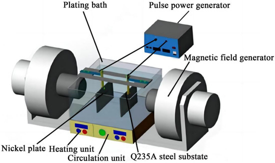
Figure 1.
Schematic diagram for preparing Ni–Co-SiC coatings.

Table 1.
Operation parameters and electrolyte ingredients for depositing Ni-Co-SiC coatings.
For electroplating, the Q235A steel plate is polished with sandpapers (grit sizes 800, 1000, and 1500) to prepare it for pulsed ED. The surface is then cleaned using a chemical reagent (see Table 2) to remove any rust and oil, followed by rinsing with distilled water. After activating the surface with 0.5 M HCl, the substrate is submerged in the electrolyte for deposition.
Table 2.
Chemical reagents for depositing the substrates.
The chosen electrolyte composition ensures efficient electrodeposition. Nickel sulfate hexahydrate (NiSO4·6H2O) and nickel chloride hydrate (NiCl2·H2O) provide the main source of nickel ions, while boric acid (H3BO3) maintains a stable pH and improves the deposition process. SiC nanoparticles are added to the electrolyte at a concentration of 8 g/L to provide a reinforcing phase for the coating, enhancing wear and corrosion resistance. Cetyltrimethyl ammonium bromide (65 mg/L) acts as a surfactant to ensure that the nanoparticles are well dispersed. The selected current density (5 A/dm2), duty cycle (60%), and pulse frequency (10 Hz) are optimized to achieve uniform, dense coatings. The operating temperature of 48 °C is crucial for consistent deposition, promoting optimal adhesion and microstructure. The application of a temporary 0.4 T magnetic field, generated only during the experiment, enhances the homogeneous dispersion of SiC nanoparticles. By altering the magnetic field direction (perpendicular versus parallel to the electric field), we can evaluate the impact of this directional difference on the coating’s microstructure, composition, and performance. This allows for a comprehensive understanding of how magnetic field orientation influences the deposition process and the resulting characteristics of the coatings.
The MS0 coating, produced without a magnetic field, serves as a control. The MS1 and MS2 coatings are fabricated under a 0.4 T magnetic field applied perpendicular and parallel to the electric field, respectively. These conditions ensure comprehensive testing of the effects of magnetic field direction on the coating structure and performance.
2.2. Characterization
SEM was employed to investigate the surface topologies of the Ni–Co–SiC coatings both before and following corrosion experiments, while TEM was used to measure the microstructures of the fabricated coatings. The crystallinity of the coatings was investigated via XRD with a scan range of 30° to 100° and a scan rate of 0.02°/s. Equation (1) was used to determine the mean grain sizes of the Ni–Co-SiC coatings [16].
where D signifies the average size of crystallite, λ represents the diffraction wavelength (1.5418 Å), and B denotes the full width of the peak at its half maximum for an angle θ.
The value of microhardness for the Ni–Co–SiC coatings was measured through a VTD510 microhardness tester. The microhardness of Ni–Co–SiC coatings was determined by averaging five randomly chosen test sites in the cross regions. The friction wear tester (MR-H5A) was used to determine the Ni–Co–SiC coatings’ friction coefficients. Reciprocating ball-on-flat wear experiments were carried out via a chromium ball (3 mm diameter) rotating at 100 rpm on the coated sample surface. These experiments were conducted for 60 min under a 10 N applied load. All experiments were carried out under ambient temperature conditions.
The electrochemical characteristics of the Ni–Co–SiC coatings were investigated via an electrochemical workstation (CS350). A platinum plate, the coating sample, and a saturated calomel electrode (SCE) were employed as auxiliary, working, and reference electrodes, respectively. The Ni–Co-SiC coatings were placed in a solution of NaCl electrolyte (3.5 wt.%) at ambient temperature, and the 0.5 mV/s scan rate was employed for experimentation. A sinusoidal signal with an amplitude of 1 mV was employed to acquire electrochemical impedance spectroscopy (EIS curves at frequencies ranging from 100 kHz to 100 mHz).
3. Results and Discussion
3.1. Microstructure and Surface Morphology
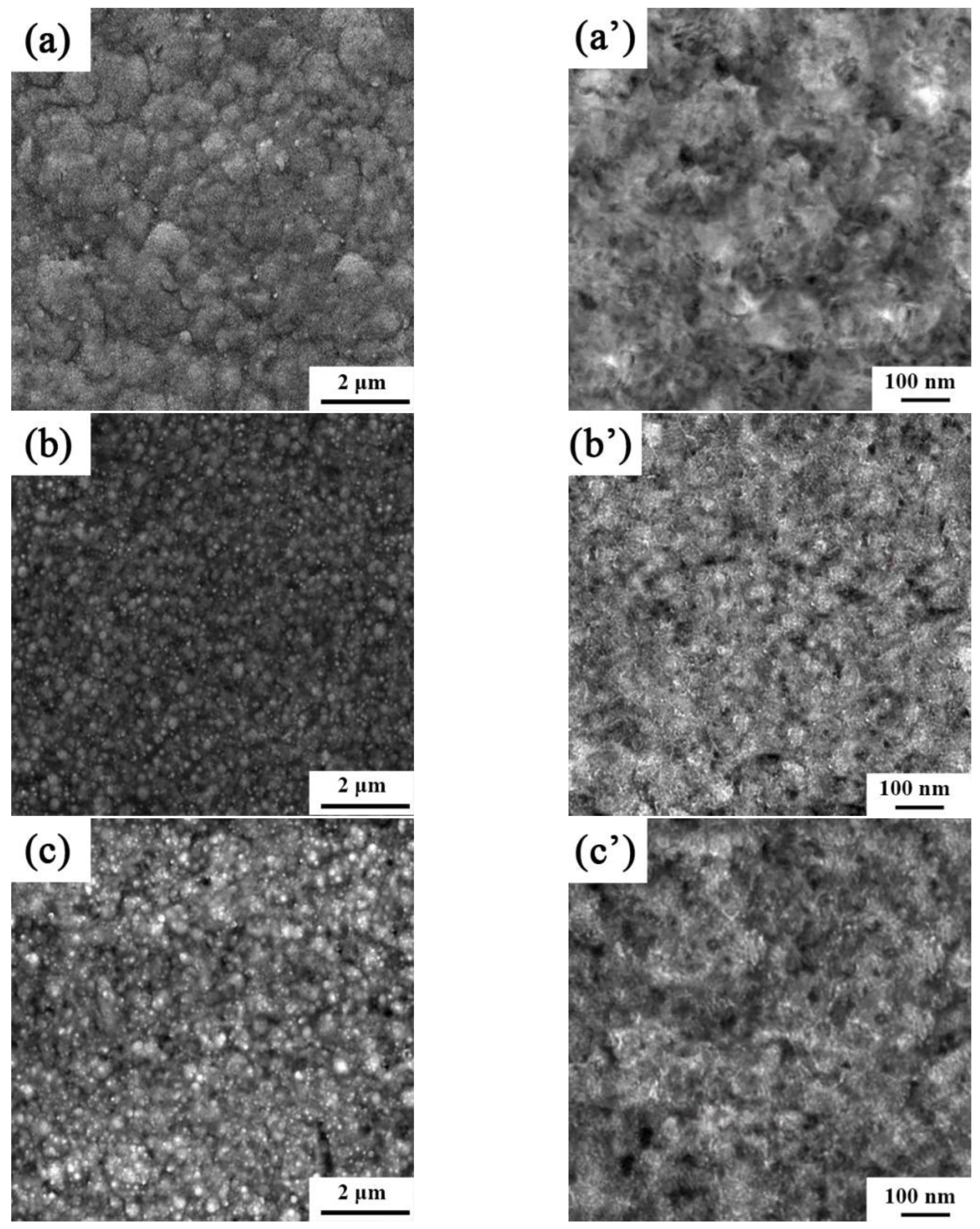
The microstructures and surface topologies of the Ni-Co-SiC coatings coated in the presence of a magnetic field being applied in different directions are depicted in Figure 2, and the mean sizes of the SiC nanoparticles and NiCo grains in the coatings are displayed in Table 3. The MS0 coating shows the significant aggregation of SiC particles and the existence of some surface pores. SiC nanoparticles and NiCo grains in MS0 had average sizes of 87.8 nm and 138.8 nm, respectively. However, the MS2 coating surface was comparatively compact and dense. Furthermore, the NiCo grain sizes of the MS1 and MS2 coatings were 86.5 nm and 98.1 nm, respectively. MS1 had the smoothest and most compact surface of the three coatings. SiC nanoparticles in MS1 had an average size of 44.2 nm. The enhanced energy of the nanomaterials at the surface that enabled the SiC particle to easily recombine in Ni-Co-SiC coatings was revealed to be the cause of the variation in the particle sizes of SiC in the three coatings.

Figure 2.
SEM and TEM images of different Ni-Co-SiC coatings: (a) and (a’) MS0, (b) and (b’) MS1, and (c) and (c’) MS2.
Table 3.
Average sizes of Ni grains and SiC nanoparticles in Ni-Co-SiC coatings.
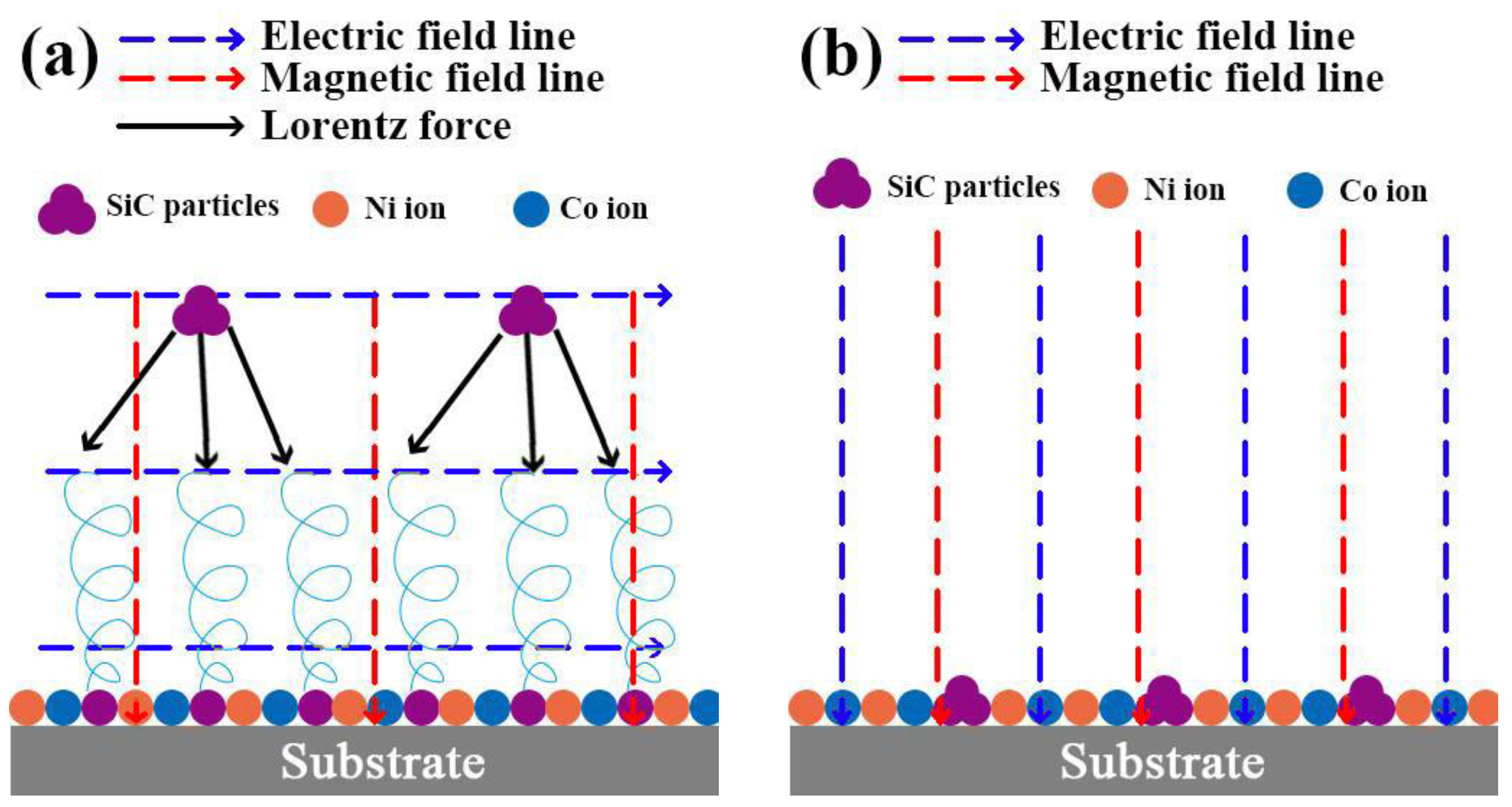
The following mechanisms account for these observations. (1) When the magnetic field is oriented at right angles to the applied electric field, it induces a Lorentz force (refer to Figure 3a), thereby causing the MHD effect. This effect, as previously reported in the research by Waware et al., decreases the gravitational sedimentation and agglomeration of SiC particles within the electrolyte [17]. As a result, the Ni-Co-SiC coating forms a compact and smooth surface (Figure 2b). On the other hand, in the case where the magnetic field is along the direction as the electric field (see Figure 3b), the agglomerated particles of SiC disperse throughout the substrate surface. (2) The MHD effect facilitates electrolyte mixing that proves advantageous for detaching hydrogen bubbles adhered to the surface of the cathode and reducing concentration polarization. This conclusion corresponds to the findings reported by Rao et al. [18]. (3) Microscale vortex convection occurs when the electric and magnetic fields are parallel to each other, improving the electrolyte’s mass transport [19]. (4) The magnetization effect lowers the energy required for the deposition of ions onto the cathode surface during ED. Thus, the more homogeneous, compact, and flat surface topologies seen for MS1 and MS2 in comparison to MS0 can be attributed to the magnetization and MHD effects.
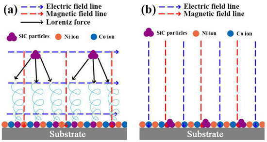
Figure 3.
Effect of different magnetic field directions on the Lorentz force: (a) perpendicular to the electric field and (b) parallel to electric field.
The findings of EDS of the Ni–Co–SiC coatings coated at various magnetic field directions are depicted in Figure 4. The specific contents of each element are shown in Table 4. The SiC contents of the MS2, MS1, and MS0 coatings were found to be 10.26, 12.31, and 8.96 wt.%, respectively. Introducing a magnetic field during the ED process led to an enhanced SiC content observed in the prepared coating. Moreover, the content of SiC improved considerably by applying the field at right angles to the electric field instead of applying it along its direction. The findings of this study support the findings of Hu et al. that applying a magnetic field improves the deposition of SiC particles [20].
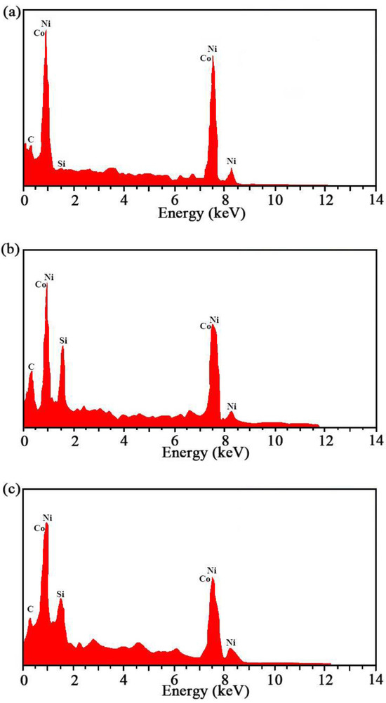
Figure 4.
EDS results of Ni-Co-SiC coatings: (a) MS0, (b) MS1, and (c) MS2.
Table 4.
Specific content of each element.
The application of a magnetic field during the electrodeposition process influences the chemical composition of the coatings through several mechanisms. The magnetic stirring and magnetohydrodynamic effects promote the uniform dispersion and incorporation of SiC particles by reducing sedimentation and agglomeration. Additionally, the magnetic field gradient alters the migration rates of ions such as nickel and cobalt, affecting the overall elemental composition of the coatings. The presence of a magnetic field also enhances the number of nucleation sites, which reduces grain growth and facilitates the embedding of SiC nanoparticles. As a result, the coating produced under a perpendicular magnetic field (MS1) exhibits the highest SiC content due to the optimal distribution and incorporation of reinforcing particles. These mechanisms lead to more homogeneous, dense coatings that exhibit improved performance.
The identification of NiCo grains and SiC nanoparticles in the SEM images was confirmed through energy-dispersive spectroscopy (EDS), which revealed characteristic peaks for the elements Ni, Co, Si, and C, providing direct evidence of their presence. The observed morphological features in the SEM images align with the expected size distribution and composition of NiCo grains and SiC nanoparticles, as reported by the manufacturer. Furthermore, cross-referencing with similar studies in the literature confirmed that the particle sizes and distributions correspond to known characteristics of these materials [21,22]. By combining SEM, EDS, and transmission electron microscopy (TEM) data, the identification of the NiCo grains and SiC nanoparticles was accurately confirmed, ensuring the reliability of the analysis.
3.2. Surface Roughness
The AFM images obtained for the Ni–Co–SiC coatings are depicted in Figure 5. The surface structure of MS0 showed roughness, characterized by a contour arithmetic mean deviation (Ra) (147 nm). The coatings applied in a magnetic field led to a decrease in SiC particle aggregation and a refinement of Ni grain size. MS1 revealed significantly lower surface roughness (Ra of 76 nm) than MS0. Moreover, MS2 had a Ra value of 125 nm. According to Liu et al. [23], the grain growth rate and number of nucleation sites have significant effects on the roughness of Ni-TiN coatings. Applying a magnetic field at right angles to the electric field produces the MHD effect, which leads to the production of a large number of SiC particles that inhibit grain growth and serve as nucleation sites. As a result, compared to MS0 and MS2, the Ra value of MS1 was significantly lower.
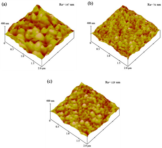
Figure 5.
AFM pictures of various Ni-Co-SiC coatings: (a) MS0, (b) MS1, and (c) MS2.
3.3. Crystallinity
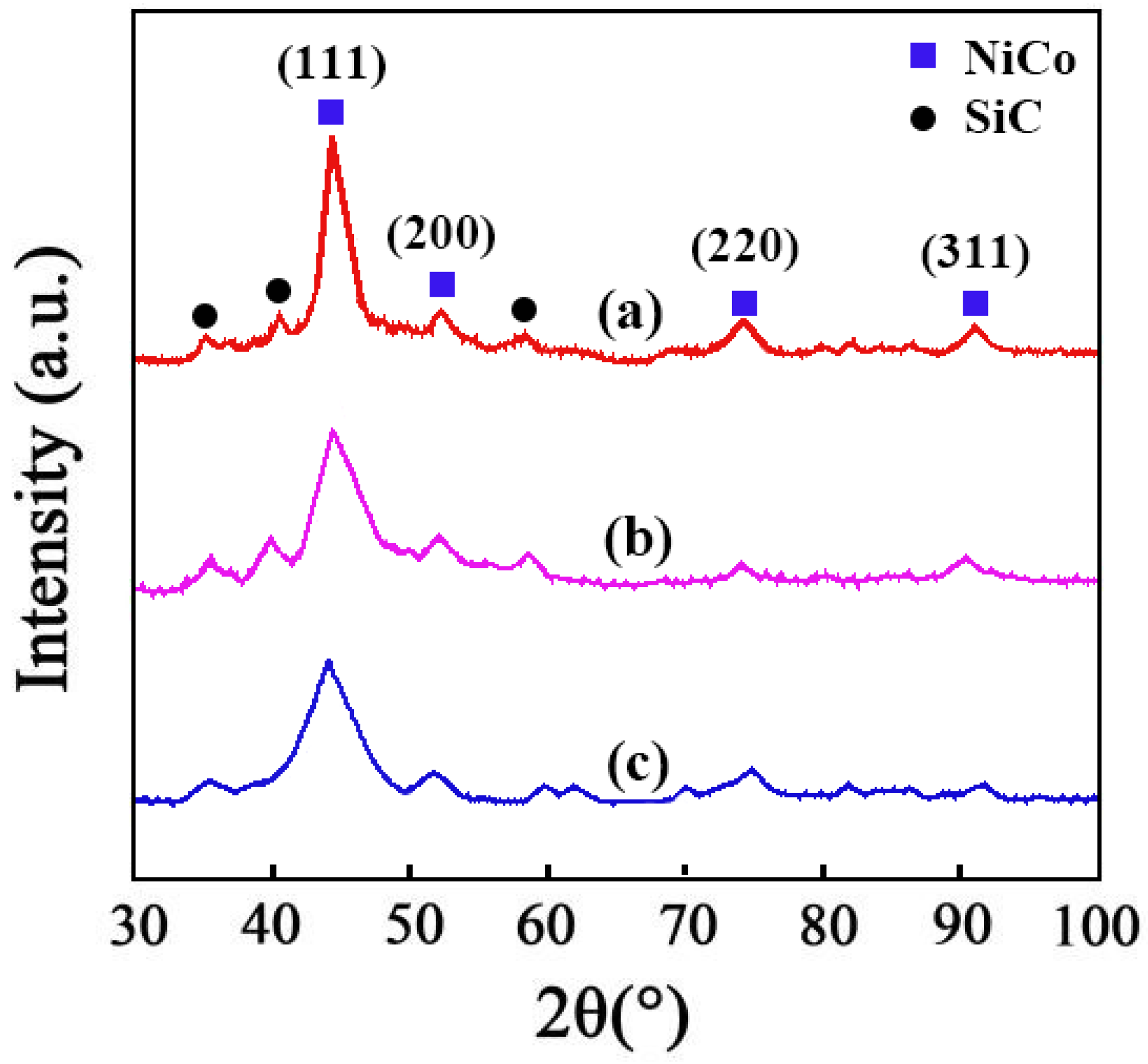
The results of XRD of the Ni–Co–SiC coatings are displayed in Figure 6. Diffraction peaks for NiCo detected at 92.4°, 76.8°, 52.4°, and 44.6° were ascribed to the planar directions (311), (220), (200), and (111), respectively. Employing a magnetic field during the SiC ED process caused the preferred orientation and size of NiCo grains to change from (200) to (111), as evident from the findings of XRD. The (111) crystal plane was not significantly affected by the magnetic direction, but the crystal plane of (200) was significantly impacted. The magnetic field employed perpendicularly revealed a greater effect on the intensity of diffraction peaks in comparison to the parallel magnetic field. The following mechanisms account for these results. (1) The SiC particles function as sites for the nucleation process and obstruct the growth of the (200) NiCo grains. (2) The magnetic field also lowers the necessary energy barrier for the surface diffusion of Ni2+ and Co2+ ions in the planar direction (220), which accelerates the formation of (220) NiCo grains and causes the transition from (220) to (111) [24].

Figure 6.
XRD patterns of different Ni-Co-SiC coatings: (a) MS0, (b) MS1, and (c) MS2.
3.4. Abrasion Resistance
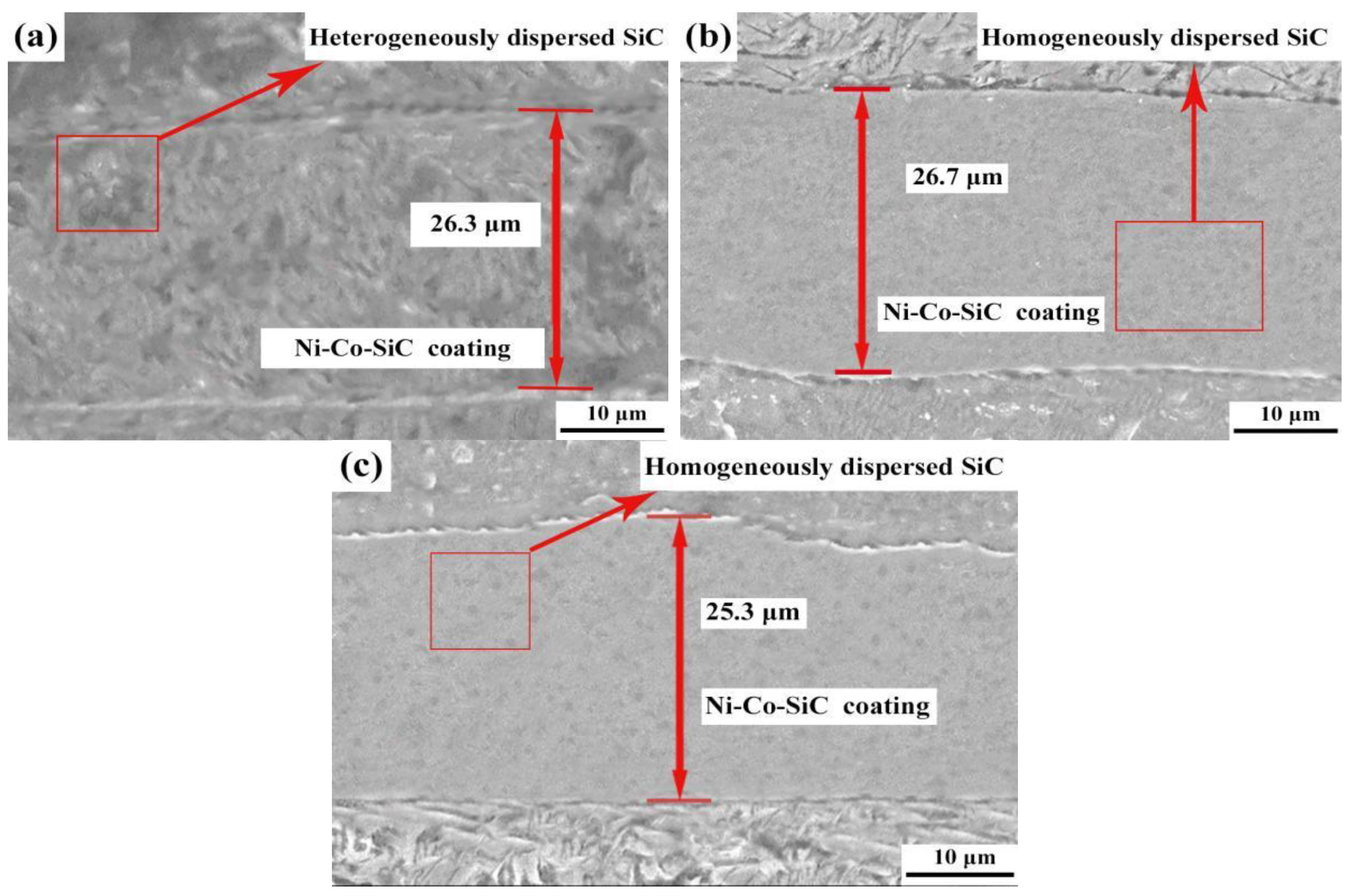
The cross-sectional topologies obtained for various Ni-Co-SiC coatings are shown in Figure 7. The MS2, MS1, and MS0 had thickness values of 25.3, 26.7, and 26.3 μm, respectively.

Figure 7.
Cross regions of different Ni-Co-SiC coatings: (a) MS0, (b) MS1, and (c) MS2.
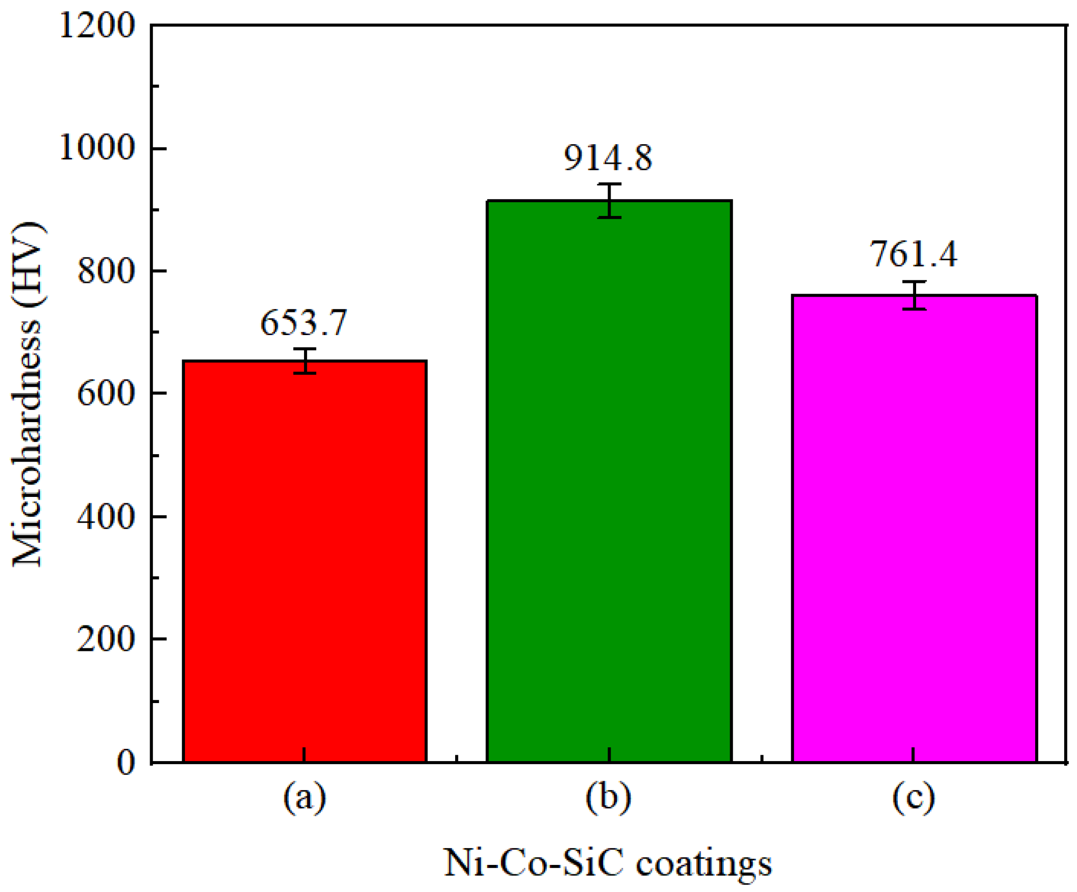
The hardness values of different Ni–Co–SiC coatings are depicted in Figure 8. The MS2, MS1, and MS0 had mean microhardness values (761.4, 914.8, and 653.7 HV), respectively. According to Huang et al. [25], an enhanced microhardness is caused by the homogeneous distribution of ceramic particles. The homogeneous distribution of SiC particles in the coatings enhanced the impact of dispersion hardening and fine crystal strengthening on Ni–SiC coatings [26]. This led to an increase in the mean microhardness values of MS1 and MS2 coatings. Moreover, compared to Ni grains, the SiC particles revealed improved microhardness. Thus, the enhanced SiC content observed in MS1 (Figure 4b) correlates with its improved microhardness.
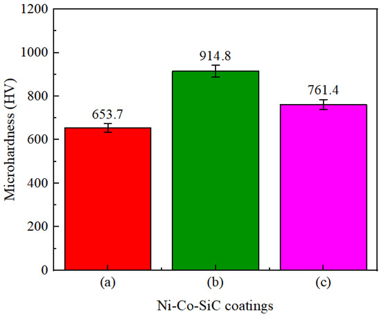
Figure 8.
Microhardness values of Ni-Co-SiC coatings: (a) MS0, (b) MS1, and (c) MS2.
The friction coefficients of MS2, MS1, and MS0 were found to be 0.51, 0.29, and 0.68, respectively (Figure 9). SiC particle concentration improved due to the magnetic field application during the ED, which decreased SiC particle agglomeration. Therefore, MS1 had the lowest friction coefficient of the three coatings due to the formation of a compact and smooth surface morphology [27].
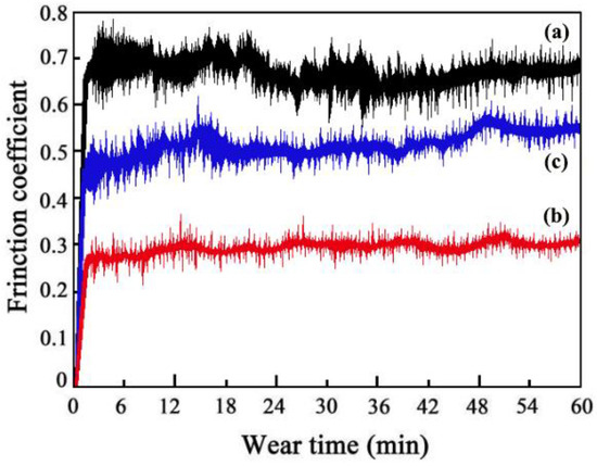
Figure 9.
Friction coefficients of Ni-Co-SiC coatings: (a) MS0, (b) MS1, and (c) MS2.
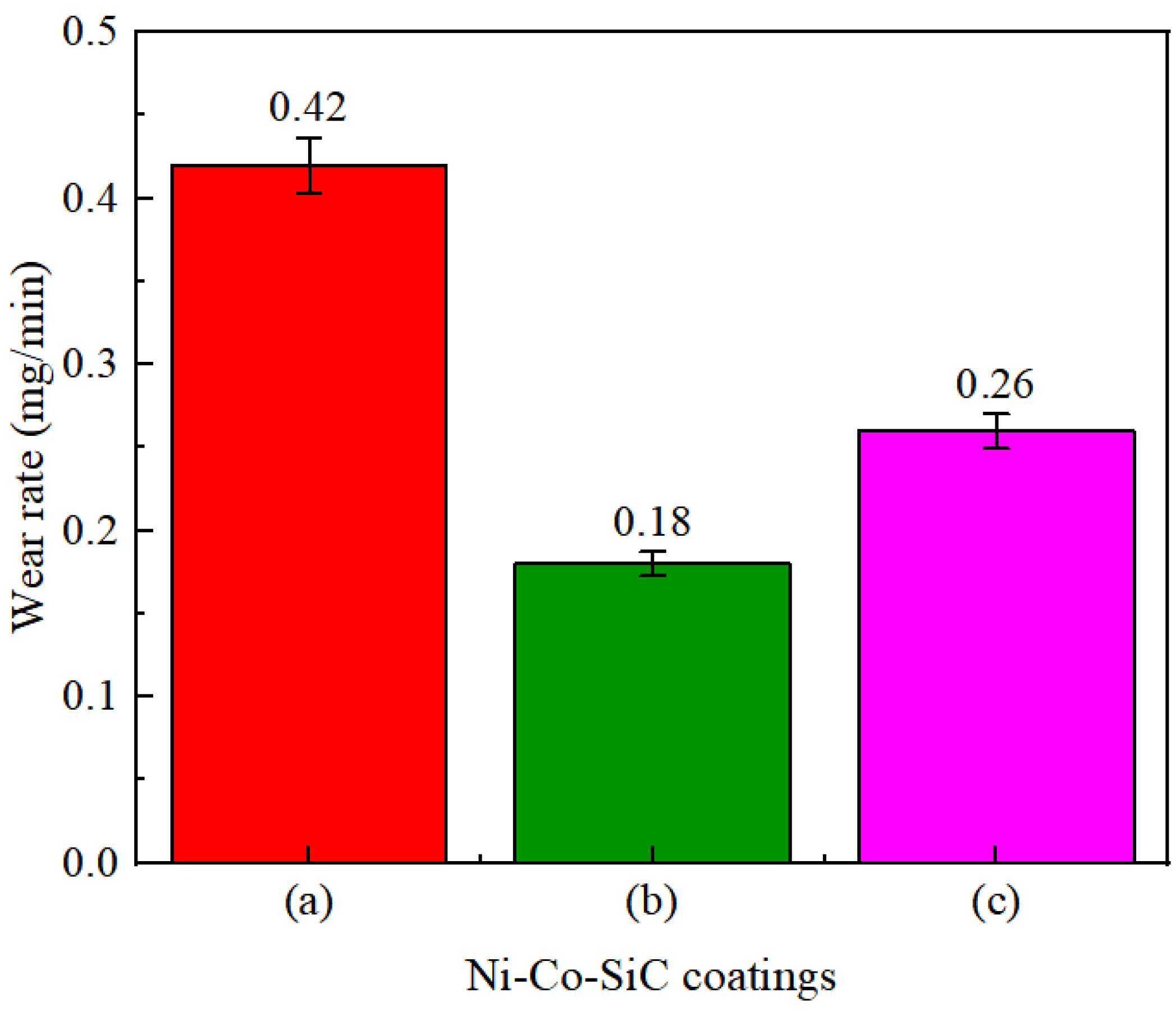
The wear rates determined for various Ni-Co-SiC coatings are displayed in Figure 10. The MS2, MS1, and MS0 showed wear rates of 0.26, 0.18, and 0.42 mg/min, respectively. The distribution and content of SiC particles incorporated in Ni-Co-SiC coatings showed a substantial impact on their wear rate. To enhance the SiC nanoparticles content and facilitate their homogeneous distribution throughout the coating, a perpendicular magnetic field was employed during the ED. This enhanced the hardness of the coating. As a result, in comparison to other coatings, the MS1 coating displayed the lowest wear rate. Employing a parallel magnetic field in the ED process induced microscale vertex convection, thereby increasing the electrolyte mass transfer of the electrolyte and enhancing the introduction of SiC nanoparticles in MS2. As a result, compared to MS2 coating, MS0 coating had a greater wear rate (Figure 10a).

Figure 10.
Wear rates of different Ni-Co-SiC coatings: (a) MS0, (b) MS1, and (c) MS2.
3.5. Corrosion Resistance
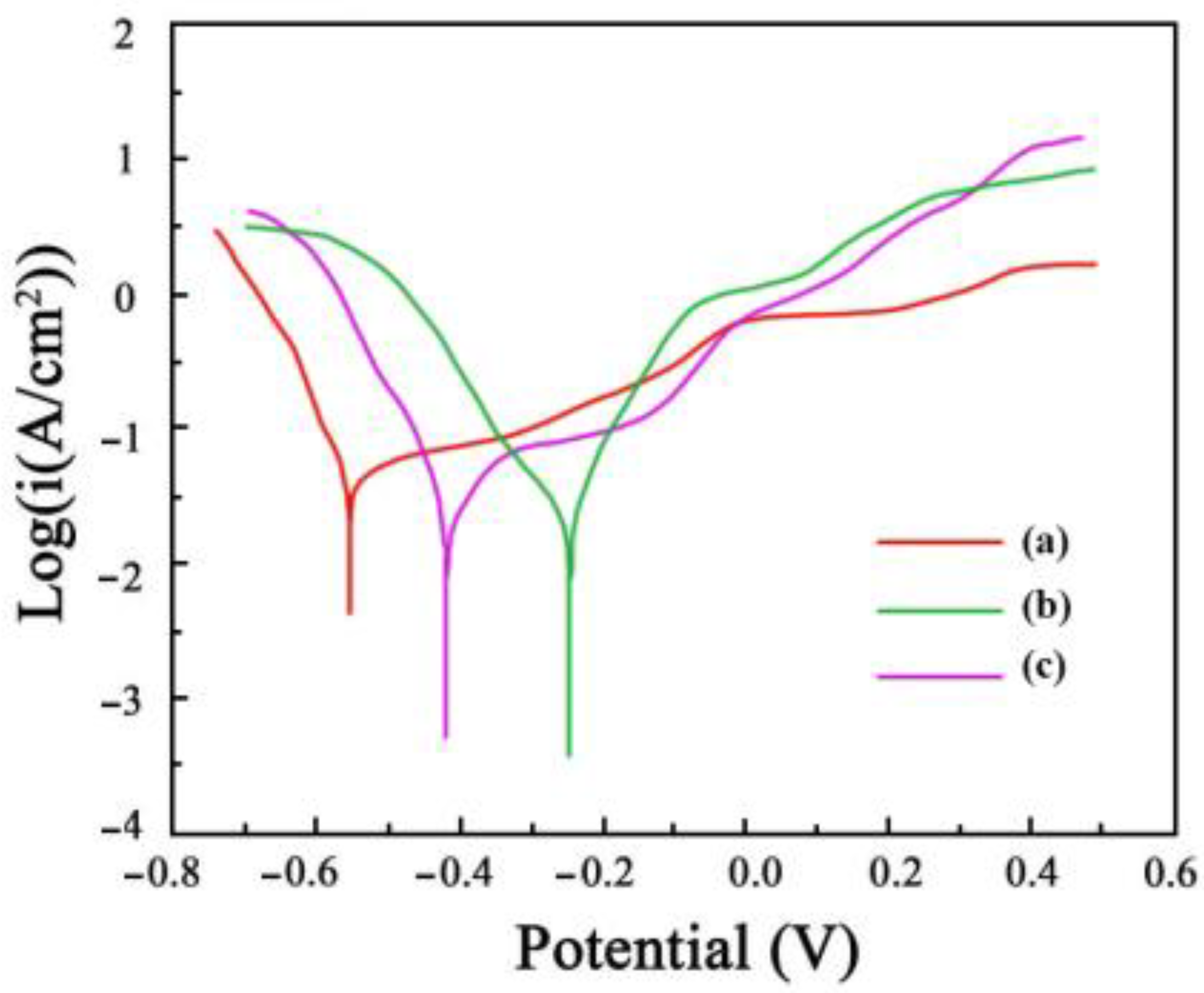
The polarization curves that were acquired for the Ni-Co-SiC coatings in a solution of NaCl (3.5 wt.%) are shown in Figure 11. It is reported that a high corrosion potential, and a low corrosion current reveal the effective resistance of a coating against corrosion in a solution of NaCl (3.5 wt.%). The corrosion potential and current of MS1 were determined to be −257 mV and 0.487 μA/cm2, respectively, whereas those of MS0 were at −573 mV and 2.358 μA/cm2, respectively. These values suggest the enhanced corrosion resistance of MS1 in comparison to MS0. Furthermore, the corrosion rates of MS0, MS1, and MS2 coatings were 3.91 × 10⁻³, 7.67 × 10⁻⁴, and 2.28 × 10⁻³ mm/a, respectively.
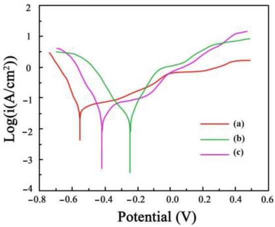
Figure 11.
Polarization curves of Ni-Co-SiC coatings in the 3.5 wt.% NaCl solution: (a) MS0, (b) MS1, and (c) MS2.
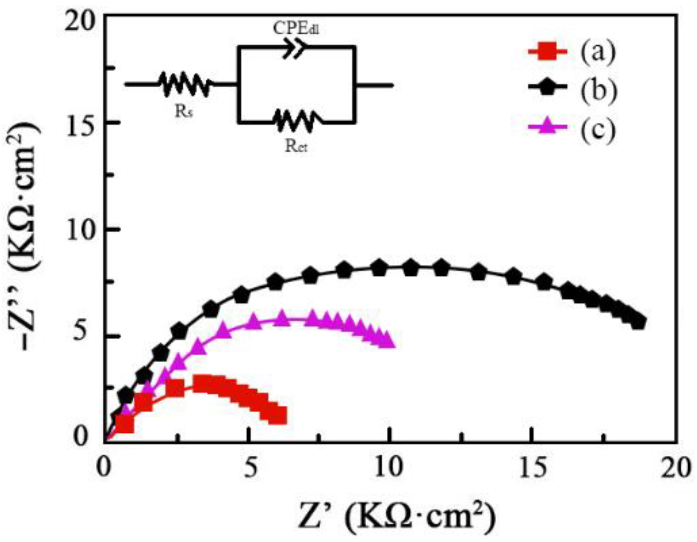
The amplitude–phase frequency response employed to study the corrosion characteristics of Ni–Co–SiC coatings is provided in Figure 12. The electric double-layer capacity, charge transfer resistance, and solution resistance are represented as CPEdl, Rct, and Rs, respectively. Peng et al., reported that reduced impedance of coatings and poor corrosion resistance are linked [28]. The improved corrosion resistance of MS1 was revealed by its significantly bigger impedance value compared to that of MS2 and MS0. This result is correlated with the polarization curves that were obtained for the Ni–SiC coatings (see Figure 11). By fitting the equivalent circuit model shown in the figure, the following quantitative values were obtained for different coatings as shown in Table 5.

Figure 12.
Nyquist plots for corrosion behavior of Ni-Co-SiC coatings: (a) MS0, (b) MS1, and (c) MS2.
Table 5.
The quantitative values for different coatings.
The charge transfer resistance Rct is a significant indicator of corrosion resistance, as a higher value implies better protection against corrosion. The results show that the MS1 coating has the highest Rct value of 15.93 kΩ, indicating the best corrosion resistance among the coatings. This finding aligns with the polarization curves (Figure 11), which also demonstrate the enhanced corrosion resistance of the MS1 coating.
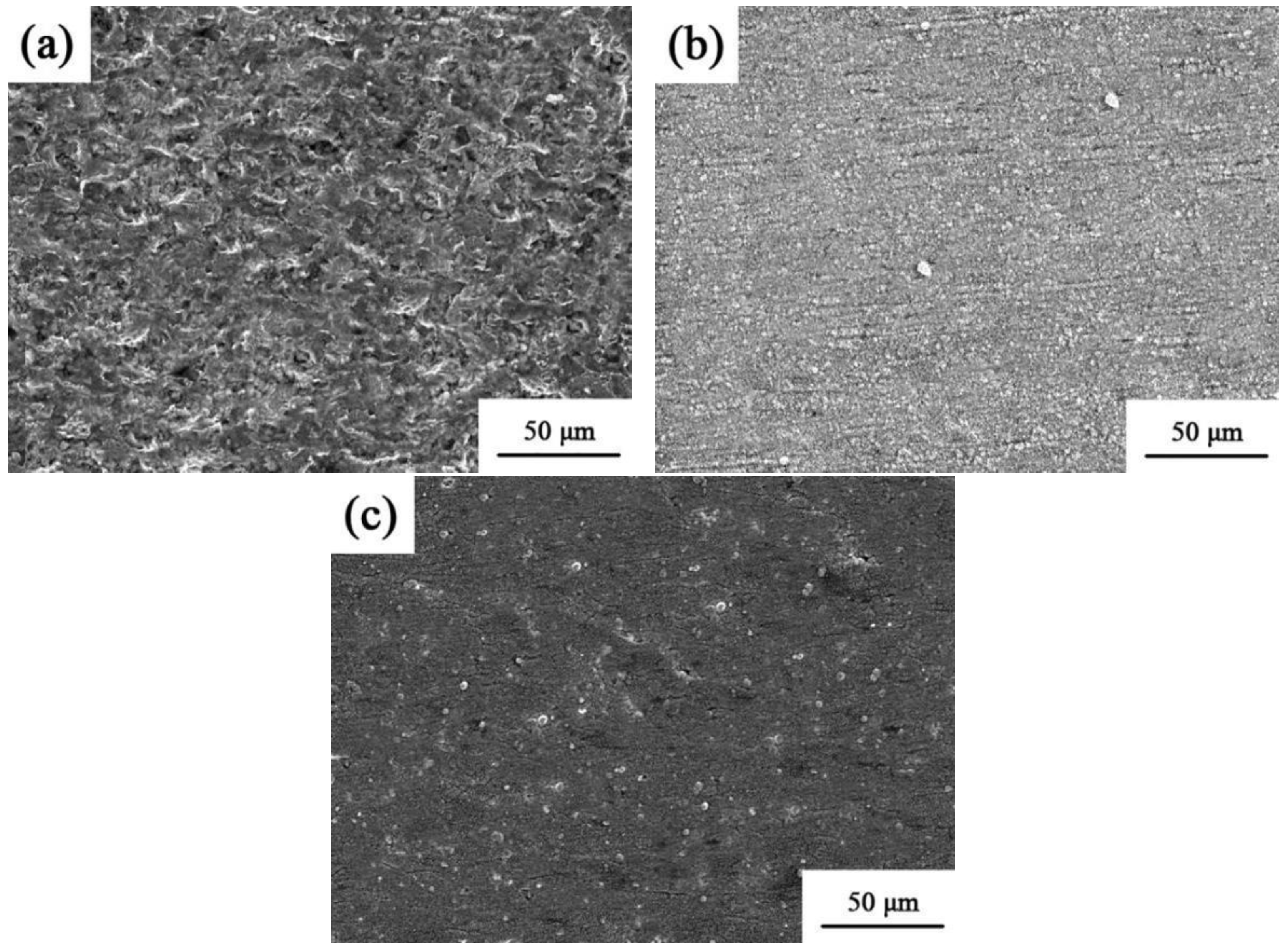
The corrosion topology of the Ni–Co–SiC coatings is displayed in Figure 13. Corrosion tests revealed many holes and severe surface deterioration on MS0. However, there was less corrosion damage on the coatings produced in the magnetic field. It is evident from Figure 13b that MS1 experienced less corrosion damage than MS2. This finding provides evidence that the magnetic field aids in the densification of the structure and grain refinement, leading to a decreased area of contact between the coating and corrosion solution [29]. Furthermore, the homogeneous dispersion of the SiC particles throughout the coatings elongates the corrosion pathway for Cl− ions, consequently improving the corrosion resistance of the prepared coating [30].

Figure 13.
Corrosion morphologies of various Ni-Co-SiC coatings: (a) MS0, (b) MS1, and (c) MS2.
The application of a magnetic field during electrodeposition significantly influenced the structure and properties of the Ni-Co-SiC coatings. Coatings prepared with a perpendicular magnetic field (MS1) demonstrated superior corrosion resistance, wear resistance, and mechanical properties compared to coatings prepared without a magnetic field (MS0) or with a parallel magnetic field (MS2). The enhanced performance can be attributed to the uniform dispersion and incorporation of SiC nanoparticles, creating a denser and more homogeneous coating structure. This technology for producing nanoparticle-reinforced coatings under a magnetic field can be valuable for modern industry. By tailoring the magnetic field direction and intensity, manufacturers can create coatings with enhanced hardness, corrosion resistance, and wear resistance, extending the lifespan and improving the performance of critical components in sectors such as aerospace, automotive, and marine engineering. This magnetic-field-assisted electrodeposition process offers a scalable and customizable solution for industries seeking to enhance the durability and efficiency of their machinery and equipment.
4. Conclusions
- (1)
- The patterns of influence of magnetic field strength (0 T-MS0, 0.4 T-MS1 magnetic field direction perpendicular, 0.4 T-MS2 magnetic field direction parallel) on the characteristics and structure of electrodeposited (ED) Ni-Co-SiC coatings were studied.
- (2)
- Employing a magnetic field during the ED led to a denser and smoother surface morphology. Furthermore, MS1 revealed the most SiC content of all coatings and the smallest NiCo grain size, measuring just 86.5 nm.
- (3)
- NiCo diffraction peaks observed at 92.4°, 76.8°, 52.4°, and 44.6° corresponded to the (311), (220), (200), and (111) crystal planes. The preferential growth direction of the Ni grains shifted from (200) to the (111) planar direction with the introduction of a magnetic field. Furthermore, the NiCo grain diffraction peak intensity was most influenced by the perpendicular magnetic field.
- (4)
- MS1 revealed the lowest friction coefficient and the highest microhardness among all prepared coatings, suggesting enhanced abrasion resistance. Furthermore, MS1 showed higher corrosion resistance than MS0 and MS2 coatings.
Author Contributions
Conceptualization, Z.L.; Methodology, H.Z.; Validation, H.Z.; Investigation, L.W.; Resources, H.H.; Data curation, H.H.; Writing—original draft, Z.L.; Writing—review & editing, C.M.; Supervision, F.X.; Funding acquisition, C.M. All authors have read and agreed to the published version of the manuscript.
Funding
The research is supported by the China Postdoctoral Science Foundation (grant no. 2023M740583), the Key Project of Qiqihar City Science and Technology Plan (grant no. ZDGG-202201), and the Basic Scientific Research Business Expenses Project of Heilongjiang Provincial Undergraduate University (grant no. 145209407).
Institutional Review Board Statement
Not applicable.
Informed Consent Statement
Not applicable.
Data Availability Statement
Data are contained within the article.
Conflicts of Interest
The authors declare no conflicts of interest.
References
- Liu, W.Q.; Lei, W.N.; Shen, Y.; Wang, C.Y.; Qian, H.F.; Lim, Q.L. Performance characterization and preparation of Ni-SiC nanocomposites based on SCF-CO2. Integr. Ferroelectr. 2017, 179, 45–55. [Google Scholar] [CrossRef]
- Jiménez-Solano, A.; Galisteo-López, J.F.; Míguez, H. Flexible and adaptable light-emitting coatings for arbitrary metal surfaces based on optical Tamm mode coupling. Adv. Opt. Mater. 2017, 6, 1700560. [Google Scholar] [CrossRef]
- Liu, Y.; Han, X.G.; Kang, L.; Li, Q. Process prediction of Ni-SiC coatings based on RBF-BP model. J. Indian Chem. Soc. 2022, 99, 100513. [Google Scholar] [CrossRef]
- Xia, F.; Yan, P.; Ma, C.; Zhang, Y.; Li, H. Pulse-electrodeposited Ni/W-Al2O3 nanocomposites at different current densities. J. Nanopart. Res. 2023, 25, 208. [Google Scholar] [CrossRef]
- Kumar, K.A.; Mohan, P.; Kalaignan, G.P.; Muralidharan, V.S. Electrodeposition and characterization of Ni-ZrO2 nanocomposites by direct and pulse current methods. J. Nanosci. Nanotechnol. 2013, 12, 8364–8371. [Google Scholar] [CrossRef] [PubMed]
- Khoran, E.; Zandrahimi, M.; Ebrahimifar, H. Microstructure and oxidation behavior of Ni-TiO2 composite coating at high temperature. Oxid. Met. 2019, 91, 177–189. [Google Scholar] [CrossRef]
- Sun, C.F.; Liu, X.Q.; Zhou, C.Y.; Wang, C.N.; Cao, H.W. Preparation and wear properties of magnetic assisted pulse electrodeposited Ni-SiC nanocoatings. Ceram. Int. 2019, 45, 1348–1355. [Google Scholar] [CrossRef]
- Azizi-Nour, J.; Nasirpouri, F. Exploiting magnetic sediment co-electrodeposition mechanism in Ni-Al2O3 nanocomposite coatings. J. Electroanal. Chem. 2022, 907, 116052. [Google Scholar] [CrossRef]
- Long, Q.; Zhong, Y.B.; Wu, J.M. Research progress of magnetic field techniques for electrodeposition of coating. Int. J. Electrochem. Sci. 2020, 15, 8026–8040. [Google Scholar] [CrossRef]
- Yang, X.Y.; Li, K.J.; Peng, X.; Wang, F.H. Beneficial effects of Co2+ on co-electrodeposited Ni-SiC nanocomposite coating. Trans. Nonferrous Met. Soc. China 2009, 19, 119–124. [Google Scholar] [CrossRef]
- Cai, C.; Yin, J.Y.; Zhang, Z.; Yang, J.F. The electrodeposition of nanostructured Ni-TiN composite films. Mater. Sci. Forum 2009, 620–622, 727–730. [Google Scholar] [CrossRef]
- Yang, G.R.; Song, W.M.; Sun, X.M.; Ma, Y.; Lu, J.J.; Hao, Y. The wear behavior of electroless Ni-P/SiC composite coating. Adv. Mater. Res. 2011, 239–242, 954–957. [Google Scholar] [CrossRef]
- Wang, X.Y.; Cui, H.X.; Zhou, Q.; Zhang, X.L.; Zhang, Y.R. Microhardness and corrosion resistance of electrodeposited Ni-SiC-BN composite coatings. Int. J. Electrochem. Sci. 2022, 17, 220677. [Google Scholar] [CrossRef]
- Wang, Q.W.; Huang, J.L.; Liu, J.N.; Yang, Y.F.; Han, G.F.; Li, W. Enhanced performance of electrodeposited Ni-SiC plating as an alternative to electroplated chromium deposits: The effect of pulse duty cycle. Surf. Topogr.-Metrol. Prop. 2022, 10, 15024. [Google Scholar] [CrossRef]
- Wasekar, N.; Latha, S.; Ramakrishna, M.; Rao, D.; Sundararajan, G. Pulsed electrodeposition and mechanical properties of Ni-W/SiC nano-composite coatings. Mater. Des. 2016, 112, 140–150. [Google Scholar] [CrossRef]
- Singh, J.P.; Pal, S.; SDharma, Y.K.; Nagm, A. Nd-doped CdS nano-particles: Optical band gap and urbach energy investigations. J. Opt. 2024, 1–8. [Google Scholar] [CrossRef]
- Waware, U.S.; Nazir, R.; Prasad, A.; Hamouda, A.M.S.; Pradhan, A.K.; Alshehri, M.; Syed, R.; Malik, A.; Alqahtan, M.S. Preparation and properties of electrodeposited Ni-B-V2O5 composite coatings. Surf. Coat. Technol. 2021, 409, 126888. [Google Scholar] [CrossRef]
- Rao, V.R.; Hegde, A.C. Magnetically induced codeposition of Ni-Cd alloy coatings for better corrosion protection. Ind. Eng. Chem. Res. 2014, 53, 5490–5497. [Google Scholar] [CrossRef]
- Liu, L.; Yu, X.; Zhang, W.W.; Lv, Q.Y.; Hou, L.; Fautrelle, Y.; Ren, Z.M.; Cao, G.H.; Lu, X.G.; Li, X. Strong magnetic-field-engineered porous template for fabricating hierarchical porous Ni-Co-Zn-P nanoplate arrays as battery-type electrodes of advanced all-solid-state supercapacitors. ACS Appl. Mater. Interfaces 2022, 14, 2782–2793. [Google Scholar] [CrossRef]
- Hu, F.; Chan, K.C.; Song, S.Z.; Yang, X.J. Enhancement of corrosion resistance of electrocodeposited Ni-SiC composites by magnetic field. J. Solid State Electrochem. 2007, 11, 745–750. [Google Scholar] [CrossRef]
- Bakhit, B.; Akbari, A. Synthesis and characterization of Ni-Co/SiC nanocomposite coatings using sediment co-deposition technique. J. Alloys Compd. 2013, 560, 92–104. [Google Scholar] [CrossRef]
- Ababsa, A.; Ben Temam, H.; Hasan, G.G.; Althamthami, M.; Malfi, A.N. Effect of sodium dodecyl sulfate and different SiC quantities on electrodeposited Ni-Co alloy coatings. Surf. Topogr.-Metrol. Prop. 2022, 10, 015038. [Google Scholar] [CrossRef]
- Liu, T.X.; Li, C.Y.; Li, Q.; Li, L.Z.; Xia, F.F.; Xing, H.Y.; Ma, C.Y. Synthesis and wear characterization of ultrasonic electrodeposited Ni-TiN thin coatings. Int. J. Electrochem. Sci. 2021, 16, 151028. [Google Scholar] [CrossRef]
- Zhang, Z.Q.; Jiang, C.H.; Fu, P.; Cai, F.; Ma, N.H. Microstructure and texture of electrodeposited Ni-ZrC composite coatings investigated by Rietveld XRD line profile analysis. J. Alloys Compd. 2015, 626, 118–123. [Google Scholar] [CrossRef]
- Huang, P.C.; Chou, C.C.; Wang, H.T.; Cheng, C.H.; Hou, K.H.; Ger, M.D. Tribocorrosion study of electrodeposited Ni-W alloy/BN(h) composited coatings for piston rings. Surf. Coat. Technol. 2022, 436, 128289. [Google Scholar] [CrossRef]
- Yang, Z.G.; Yi, S.J.; Cao, L.K.; Tang, S.H.; Li, Q. Process simulation and abrasion behavior of jet electrodeposited Ni-TiN nanocoatings. Coatings 2022, 12, 86. [Google Scholar] [CrossRef]
- Demir, M.; Kanca, E.; Karahan, I.S.H. Characterization of electrodeposited Ni-Cr/hBN composite coatings. J. Alloys Compd. 2020, 844, 155511. [Google Scholar] [CrossRef]
- Peng, X.S.; Xu, X.Y.; Wang, J. Characterization and performance prediction of jet pulse electrodeposited Ni-SiC nanocomposites by means of artificial neural networks. Ceram. Int. 2018, 44, 8599–8604. [Google Scholar] [CrossRef]
- Galicia-Aguilar, G.; Campo-Garcia, G.; Ramirez-Reyes, J.L.; Medina-Almazan, A.L. Study of the magnetic field effect on the electrochemical behavior of a Ni electrodeposit. Int. J. Electrochem. Sci. 2017, 12, 928–942. [Google Scholar] [CrossRef]
- Zhao, Y.T.; Wang, L.B.; Qin, Z.B.; Wang, C.X.; Xu, Z.; Jiang, C.H.; Ji, V. The roles of Ti particles in improving the corrosion resistance of electrochemically assembled Ni-Ti composite coatings. Corros. J. Sci. Eng. 2017, 73, 1107–1118. [Google Scholar] [CrossRef]


Disclaimer/Publisher’s Note: The statements, opinions and data contained in all publications are solely those of the individual author(s) and contributor(s) and not of MDPI and/or the editor(s). MDPI and/or the editor(s) disclaim responsibility for any injury to people or property resulting from any ideas, methods, instructions or products referred to in the content. |
© 2024 by the authors. Licensee MDPI, Basel, Switzerland. This article is an open access article distributed under the terms and conditions of the Creative Commons Attribution (CC BY) license (https://creativecommons.org/licenses/by/4.0/).