
Advances in Organic Multiferroic Junctions


National Institute of Materials Physics, Atomistilor 405A, 077125 Magurele, Romania
Coatings 2024, 14(6), 682; https://doi.org/10.3390/coatings14060682
Submission received: 27 April 2024
/
Revised: 23 May 2024
/
Accepted: 28 May 2024
/
Published: 30 May 2024
(This article belongs to the Special Issue Advances of Nanoparticles and Thin Films)
Abstract
:Typically, organic multiferroic junctions (OMFJs) are formed of an organic ferroelectric layer sandwiched between two ferromagnetic electrodes. The main scientific interest in OMFJs focuses on the magnetoresistive properties of the magnetic spin valve combined with the electroresistive properties associated with the ferroelectric junction. In consequence, memristive properties that couple magnetoelectric functionalities, which are one of the most active fields of research in material sciences, are opening a large spectrum of technological applications from nonvolatile memory to elements in logic circuits, sensing devices, energy harvesting and biological synapsis models in the emerging area of neuromorphic computing. The realization of these multifunctional electronic elements using organic materials is presenting various advantages related to their low-cost, versatile synthesis and low power consumption functioning for sustainable electronics; green disintegration for transient electronics; and flexibility, light weight and/or biocompatibility for flexible electronics. The purpose of this review is to address the advancement of all OMFJs including not only the achievements in the charge and spin transport through OMFJs together with the effects of electroresistance and magnetoresistance but also the challenges and ways to overcome them for the most used materials for OMFJs.
1. Introduction
Multiferroic tunnel junctions consisting of a ferroelectric barrier in magnetic spin valves were first proposed about 15 years ago [1,2,3] and are capturing considerable scientific interest, especially in the field of electric-field-controlled spintronics and information technologies. As magnetic tunnel junctions, these systems allow for the tunneling spin-polarized current to be efficiently filtered according to the orientation of the magnetization of the ferromagnetic electrodes, which generate high resistive and low resistive states for their antiparallel and parallel relative orientation, respectively, based on the tunnel magnetoresistance (MR) effect [4,5]. The activity of the ferroelectric barrier in a tunnel junction allows for switching between different resistive states defined by the orientation of its electrical polarization that alters the induced charge densities and the electrostatic potential at the barrier–electrode interface and thus the charge transport characteristics of the tunneling current, based on the electroresistance (ER) effect [6,7,8]. In addition, the piezoelectric effect of the ferroelectric that affects the strain at the interface may couple with the magnetostrictive effects of the ferromagnetic layers (Figure 1). This affects the magnetic anisotropy and the magnetization, leading to drastic changes in the magnetoresistive properties, such as the reversal of the magnetoresistance hysteresis induced, for instance, by the electrical polarization [3].
Furthermore, advanced spin and charge transport properties may be added to the multilevel-resistive or memristive states of the multiferroic junctions when the separating layer between the ferromagnetic electrodes of the junctions is an organic material. Organic electronics and spintronics constitute developing fields for the next generation of applications. For organic spintronics, the light molecular elements present weak spin–orbit and hyperfine interactions that lead to a long spin relaxation time and thus long spin transport distances even at room temperature [9,10] that open routes for their inclusion in electronic devices, such as memory and computing elements to store and process information, neuromorphic computing and models of synaptic and neuronal operations, etc. Moreover, important assets for technological applications of organic systems are the low-cost and versatile fabrication, sustainability, light weight, mechanical flexibility and the possibility of a controlled degradation for electronic waste management [11,12].
The purpose of this article is to review the major advances in OMFJs through the analysis of mechanisms, functioning and applications. It is envisaged not only to merge current scientific knowledge but also to identify new paths for research and innovation in this field. This report contains a detailed description of the main characteristics of OMFJs in Section 2 that comprise the properties of organic spin valves and organic ferroelectric junctions, respectively. This section includes the origins of the functional properties of OMFJs, i.e., the magnetoresistance and the electroresistance effects and the control of the multilevel-resistive properties with external electric and magnetic fields. Section 2.1 describes the mechanism of the spin and charge transport through organic spin valves and summarizes magnetic and organic materials that are mostly used in spin valves and can be potentially used in OMFJ junctions. Furthermore, Section 2.2 summarizes the organic ferroelectric junctions and their properties, together with a description of organic ferroelectrics. Section 3 describes the reported OMFJs, their properties that are based on the coupling of magnetoresistive and electroresistive effects and their optimal configuration for adjusted functional devices. This review also includes challenges regarding the operational processes of OMFJs, together with proposed solutions to overcome these difficulties. Finally, concluding remarks on the progress strategies in OMFJs and a general perspective are presented in Section 4.
2. Characteristics of Organic Spin Valves and Organic Ferroelectric Junctions
2.1. Magnetic Junctions and Organic Spin Valves
Magnetic junctions are originally formed of two ferromagnetic films, preferably with different magnetic coercive fields, separated by a non-magnetic spacer that can be a tunneling barrier or a spin transport medium. In magnetic tunnel junctions, the tunneling current between metallic ferromagnetic films is spin-dependent and generates a tunneling MR that is based on the relative orientation of the magnetization of the two ferromagnetic electrodes [4]. The MR ratio is defined by the Julliere expression as follows:
where Rap and Rp are resistances for the antiparallel and parallel orientations of the magnetizations, respectively, and P1, P2 are the spin polarizability of the two ferromagnetic electrodes. Equivalently, the MR is defined for spin valves where spin-polarized currents are transported through the separating medium. Usually, the MR ratio is the maximum for an antiparallel magnetic configuration and the minimum for the parallel configuration (Figure 2a). However, these values can appear reversed, leading to negative MR values, observed for different junctions (Figure 2b).
Table 1 presents most of the results encountered for magnetic junctions with an organic semiconductor spacer, i.e., organic spin valve junctions, which are composed of different materials, including small molecules that contain acenes, thiophenes, fullerenes, metal complexes and their derivatives, but also larger molecules and polymers. This table includes the chemical representation of each organic layer, the junction sequence mentioning the thickness of each system and the MR at various temperatures extracted from the corresponding references. The organic films of the junctions were deposited by physical vapor deposition techniques or wet chemical routes. The MR strongly depends on the nature of the used materials, the thickness of the organic spacer and the temperature.
The variation in the MR values of organic spin valves is related to several parameters, such as the following:
- The spin polarization of the ferromagnetic electrodes;
- Tunneling/Spin injection from the ferromagnetic electrode into the organic layer;
- Spin transport through the organic layer;
- Spin detection at the other electrode.
Therefore, the MR of the organic spin valves can also be expressed by adapting the Julliere formula as follows:
where d is usually the thickness of the spin transport medium and λs the spin diffusion length.
For efficient spin valves with high MR, the junctions preferably contain ferromagnetic electrodes with a high spin polarization. In particular, from oxides with the perovskite-based crystal structure, lanthanum strontium manganite with the general formula La1−xSrxMnO3, where x describes the doping level, known by its abbreviation LSMO, has a 100% spin polarization at low temperatures [70] and is one of the most used ferromagnetic electrodes (especially as the bottom electrode) in organic spin valves (see Table 1). As another La-comprising perovskite oxide material, (La2/3Pr1/3)5/8Ca3/8MnO3 (LPCMO) has a nearly maximum spin polarization (~97%) [71,72] and is starting to be employed in organic spin valves [36,49], leading to an incredibly large MR effect of up to 440% [36]. Moreover, it is worth to mention here the fact that LPCMO presents domains of electronic phase separation characterized by the coexistence of ferromagnetic metallic and antiferromagnetic insulating phases that can be magnetically controlled with preset magnetic fields, permitting the achievement of a nonvolatile tunable MR response in organic spin valves [36]. Starting from this result, one can imagine complex structured hybrid systems, like lateral arrays of tranches and nanowires [73,74,75,76], as templates for molecular assemblies that can provide an adjustable MR. The double perovskite Sr2FeMoO6 (SFMO) is also a potential material for organic spintronics with a high spin polarization (of 100% theoretically predicted [77] and ~85% experimentally detected [78]), used recently in organic-based junctions [37]. Additionally, magnetic oxides, such as Fe3O4 which has a high spin polarization of about -80% [79], are often used in organic spin valves [15,17,38,45]. Other materials with full spin polarization and a great potential in spintronics and multifunctional materials are Heusler compounds [80,81,82], from which Co2MnSi has a 100% spin polarization [83] and can be employed in organic spin valves [25]. Magnetic transition metals Fe (44%), Co (34%) [84] and/or alloys of these metals, including FeCo (50%) [85], NiFe (45%) [86], Ni80Fe20 (~30%) [86,87] also called permalloy (Py) and close composition alloys such as Ni81Fe19 and Ni78Fe22 have an elevated Curie temperature (>700 °C) and are often used (mostly as a top electrode) in organic junctions (see Table 1).
Depending on the thickness of the separating layer, this can serve as a spin-conserved tunneling barrier or a spin transport medium. In the case of magnetic junctions with an organic spacer, the concept of tunneling is controversial, due to hybridization effects at interfaces and to the fact that the MR response is very similar either for tunneling or spin injection. However, for very thin thicknesses of only a few nm of the organic spacer (see Table 1), the tunneling mechanism is considered [63,88,89]. For organic spin valves, there are different mechanisms regarding the spin injection. A prime factor to be considered not only for the spin injection but also for the transport and the spin collection or detection is the energy level alignment at the metal–organic interface. Thus, the position of the Fermi level (EF) of the metal with the work function (φ) in rapport with the positions of the molecular orbitals of the organic material with ionization energy (Ip) and the electron affinity energy (Ea) aligned at the vacuum level (Ev) determines the type of charge carrier. An example is shown in Figure 3. If the EF of the metal is closer to the lowest unoccupied molecular orbital (LUMO), the main charge carriers are electrons (Figure 3a). If the EF of the metal is closer to the highest occupied molecular orbital (HOMO), the main charge carriers are holes (Figure 3b). Moreover, one has to consider that because the spin polarization of the electronic states at different energy levels of the ferromagnetic electrode may be different, the spin injection and detection are likely different for different types of carriers and different energy alignments at the metal–organic interface. Additionally, alignment mismatches at interfaces may induce additional spin injection or collection problems (see, for example, Figure 3a).
Regarding the spin injection, every so often, a tunnel spin injection barrier consisting of a thin insulating film, such as AlOx which is the most used (see Table 1), MoOx [61], LAO (LaAlO3) [20] or other films, like, for example, LiF [16] or organic layers [39,41,42,51], is inserted in between the ferromagnetic electrodes and the organic spin transport medium. These layers are used to optimize and tune the spin injection through processes such as solving the energy level mismatch at interfaces or tailoring the bend bending. Moreover, the inserted interfacial layer can improve the interface qualities, like, for example, in vertical junctions, it can reduce the penetration of the top ferromagnetic metallic electrode, or an organic spinterface [90,91,92,93] can ensure a less rough interface or better anchoring and tune the interface resistance [94,95,96,97].
Recently, several innovative spin injection methods based on studies on inorganic materials were proposed. From these, ferromagnetic resonance spin pumping injection is a pure spin injection process conducted by applying an external microwave field at its resonance frequency that generates a spin precession within the ferromagnetic layer, leading to an excess of spin angular momentum. When the precession frequency fits the microwave field, pure spin currents are injected into the organic layer through exchange interactions at the metal–organic interface [98,99,100], which lead to an induced electric field based on the inverse spin Hall effect, excluding the need for a bias voltage and resolving, thus, energy level alignment mismatches at interfaces.
Hot-electron spin injection or ballistic spin injection can be implemented in a three-terminal junction that contains three metal electrodes: an emitter, a base and a collector. From these layers, either the emitter or, in most cases, because a higher spin-polarized current is generated, the base should be ferromagnetic. The emitter and the base are separated by a tunnel barrier, while between the base and the collector is the spin transport medium, i.e., the organic layer. By applying a bias voltage between the emitter and the base, hot carrier electrons (or holes) are generated into the base that exhibit a ballistic spin filter effect based on different mean free paths of the majority and minority spin in the ferromagnet leading to a very high spin-polarized current that can be injected above the LUMO level for electrons (or below the HOMO level for holes) and measured at the collector if the applied voltage exceeds the injection barrier, i.e., the Schottky barrier, at the metal–organic interface [101,102,103]. In addition, hot electrons can be generated optically, using a photon photoemission process by applying an ultrashort laser pulse that generates hot electrons into the ferromagnet, from which a fraction can be ballistically injected at the metal–organic interface into the LUMO of the organic layer. Afterward, by applying a second laser pulse, the spin-polarized electrons remaining in the organic material can be excited into the vacuum and then photoemitted and detected [104]. Regarding spin-related optical effects, it is worth mentioning the coupling with luminescent and photovoltaic process that can lead to an enhancement in the electroluminescence intensity by the spin-polarized carriers [61] and to the manipulation of the spin-related magnetic response of the junction by the intensity of an irradiating light [64,68].
Another strategy to generate spin polarization in organic materials includes the chirality-induced spin selectivity injection. This can be reached when electrons with a spin orientation like the chirality of their transport medium are selected in favor of others that do not match this criterium [105,106,107,108]. The approach can lead to very high spin polarizations, also more than 80% [109].
Moreover, charge transfer spin polarization induced by an asymmetric population of molecular orbitals can be generated at the molecular level [110,111,112].
The transport of spin-polarized carriers through the organic layer is realized mainly through a hopping mechanism; however, for molecular crystals and polymers, a band transport is possible. Exchange coupling modes may be considered as an additional contribution for a very high concentration of transport carriers in doped or impurity band organic films. The spin diffusion thorough the organic layer for the hopping mode is defined principally by two factors, the spin diffusion length (λs) and the spin relaxation time (τ), as follows:
where kB is the Boltzmann constant, T is the temperature, q is the carrier charge and μ is the mobility. Therefore, a long spin diffusion length can be reached for a long spin relaxation time and high mobility. The spin relaxation time is mainly influenced by the spin orbit coupling and the hyperfine interactions. The spin orbit coupling characterizes the interaction between the spin and the orbital angular momentum of the charge carrier, which contributes to the spin–charge conversion and the spin relaxation. Usually, the spin–orbit coupling is proportional to the fourth power of the atomic number. Thus, in organic materials that contain light-weight elements, such as C, H, N and O, the strength of the spin–orbit coupling is weak leading to an extremely long spin relaxation time. The hyperfine interaction, reported to be strong only for localized carriers, characterizes the exchange interactions between the spin of the charge carriers and of the nuclei (which are the half-integer nuclear spins of the atoms) and causes spin relaxations, as demonstrated, for instance, for deuterium/hydrogen substitution is DOO-PPV [30] where λs was increased significantly by deuteration. The mobility of the charge carriers is influenced by the molecular structure, carrier type (the mobility of electrons is higher than the one of holes), morphology of the films, packing modes, aggregations, disorder, defects, impurities and temperature. Crystals, polymers and the highly ordered stacked molecular aggregation of π-conjugated systems have a high mobility and weak spin scattering effects leading to long spin transport distances. The impact of various parameters on the spin transport and the related value of the MR can be deduced by a comparison of various organic junctions mentioned in Table 1.
The mobility for organic materials is the factor that strongly decreases λs as the spin relaxation time is high compared to inorganic materials [113].
2.2. Ferroelectric Junctions and Organic Ferroelectrics
Ferroelectric materials are dielectrics that possess a spontaneous electrical polarization whose orientation can be switched by an external electric field, with a critical value denoted the coercive field. Ferroelectrics are also pyroelectrics, piezoelectrics and present second harmonic generation properties. In ferroelectric junctions that consist of a ferroelectric film sandwiched between metallic electrodes, the current across the thick ferroelectric film (ferroelectric diode [114,115]) or the thin ferroelectric barrier (ferroelectric tunnel junction [5,6,7,8]) can be modulated by the orientation of the electrical polarization of the ferroelectric film.
The electroresistance modulation associated with the electric field-induced polarization reversal is in principle related to electrostatic effects at ferroelectric–metal interfaces. At the interface, polarization-generated charges that have different polarities in function of the orientation of the polarization will have, accordingly, an attraction or repulsion effect on the transport charge carriers. This effect arises over a short distance δ in the metal within which the electrons screen the polarization charges depending on the density of states at the Fermi level, giving rise to different δ for different metals. The incomplete screening modifies the depolarization field [7] and the electrostatic potential at each ferroelectric–metal interface (Figure 4) seen by the transport electrons [8,116]. Thus, the electronic potential profile is asymmetric and is modulated by the orientation of the polarization (Figure 5), which is controlled with an external electric field. In Figure 5, for simplicity, it is considered that the metals have a similar work function (φ1 ≈ φ2) marked as φ, while δ1 > δ2. The interface electrostatic effects are stronger as the thickness of the ferroelectric is smaller; thus, the electroresistance modulation by the orientation of the polarization is larger for ferroelectric tunnel junctions than for ferroelectric diodes. Moreover, the electroresistance values can be modulated to several resistive or also called memristive levels by applying progressive voltage pulses that partially switch the polar ferroelectric domains, which can reach a very high of a few orders of magnitude on–off ratio for the opposite orientation on the electrical polarization [117,118]. The electroresistance modulation can also be implemented in metal –organic ferroelectric–metal junctions [119,120,121,122,123,124,125]. Moreover, an electroresistance percentage (ER) can be deduced in a similar way as for magnetic spin valves described by the following:
where Rup and Rdown denote the corresponding resistance for opposite orientations of the electrical polarizations of the ferroelectric field.
Ferroelectricity appears in films or crystals of organic materials by following a few conditions, such as the following:
- the presence of electrical dipoles;
- the arrangement of the dipoles in non-centrosymmetric structures to avoid canceling each other through dipole–dipole interactions; and
- the compliance of properties with electrical polarization switching transitions that should have a sufficiently low energy-switching barrier affordable by the organic system.
The switching transitions can be associated with disorder–order transitions (which consist of rearrangements of individual molecules or of polar components) or displacive transitions (which consist of molecular displacement or of charge or ion displacement) [126,127,128]. Nevertheless, complex organic materials and metal–organic structures may include combinations of these processes. Organic ferroelectrics, depending on the composition, can be classified in the following: 1. single molecular components; 2. polymers and oligomers; 3. charge transfer complexes, or metal–organic complexes and hydrogen-bonded co-crystals. Table 2 contains a few examples for each category. In order to be included in ferroelectric junctions, ferroelectric films can be deposited by thermal evaporation, e.g., organic molecular beam epitaxy, similarly to the organic spin valves for small single-component systems, or wet chemical methods that are mostly used [119,120,121,122,123,124,125], including spin coating, drop casting, Langmuir–Blodget, etc., for polymers and other macromolecular structures.
The electrical polarization switching mechanism of organic ferroelectrics can be related to their structure and composition. The majority of single-component systems, which are mentioned in part 1 of Table 2, form crystallographic structures through hydrogen bonds such as N-H⋅⋅⋅O, O-H⋅⋅⋅N, O-H⋅⋅⋅O and N-H⋅⋅⋅N. These intermolecular interactions allow for both the disorder–order and the displacive transitions in the polarization orientation processes. Thus, electrical polarization switching involves molecular rotations (such as, for example, for thiourea [129], CDA [132], glycine [143], thymine [144]), the reorientation of functional groups (such as, for example, for TCAA [130], TEMPO [131], TCHM [133], benzil [134], DNP [135]) and the intermolecular displacement of H+ within hydrogen bonds (such as, for example, within O-H⋅⋅⋅O for squaric acid [136], CBDC [137], croconic acid [138], PhMDA [137] and 3-HPLN [137]; within N-H⋅⋅⋅N for MBI [139], DC-MBI [139], 1P [140] and guanine [142] and within N-H⋅⋅⋅O for FF [145]). The latest example can be photo-activated. Another photo-induced switching is produced by a H+ intramolecular displacement within the O-H⋅⋅⋅N bonds for SA-PFA molecules [141]. The polymeric systems that are included in part 2 of Table 2 all switch their electrical polarization by the reorientation of functional groups and rotations of polymeric chains [146,147,148,149,150,151,152]. The bicomponent systems from part 3 of Table 2 change their polarization state by electronic transfer for TTF/CA [153,154] and TTF/BA [154] and by H+ transfer within O-H⋅⋅⋅N bonds for Phz/H2ca [155], Phz/H2ba [155] and DMBP/H2ia [156]. The polarization changes for the systems in the last row of Table 2 are all produced by molecular reorientations and order–disorder transitions [157,158,159,160,161].
3. Organic Multiferroic Junctions
OMFJs can be obtained by combining the previously described devices, for instance, introducing an organic ferroelectric film as the separating medium in an organic spin valve. The main characteristic of OMFJs is the possibility to electrically control the spin polarization at the ferromagnet–organic–ferroelectric interfaces by switching the electrical polarization of the ferroelectric and thus manipulating the MR and ER effects.
These coupled processes were first demonstrated for inorganic multiferroic tunnel junctions [2,3,162]. Experimentally, recent studies on OMFJs using a few organic ferroelectric materials, such as PVDF [163,164,165], P(VDF-TrFE) [166,167] and croconic acid [168], have confirmed their memristive behavior manipulated with electric and magnetic stimuli. The rich variety of possibilities (see Table 2) of including other ferroelectric organic and biomolecular materials in OMFJs opens further routes for tuning the magnetoelectric and electronic/spintronic properties of these systems. As for any other organic spin valves and ferroelectric junctions, the MR and ER effects depend on other parameters and conditions. Moreover, the ferroelectric control of the spin polarization can induce the reversal of the magnetoresistance hysteresis (see Figure 2), i.e., the spin rectification effect, by switching the electrical polarization.
The MR effect of OMFJs, as for any organic spin valve, strongly depends on temperature and the thickness of the organic film. Expected consequences of these factors can be observed on the examples represented in Figure 6a–d. Moreover, the ER effect is also affected by these parameters (Figure 6d). Furthermore, the interfaces play a crucial role in defining the MR, ER and the coupled effects. For LSMO/PVDF/Co systems presented in Figure 6c,e, the PVDF/Co interface is different as the Co layer was deposited at low and room temperature, respectively. The MR for a supposedly rougher interface, with diffusion channels that also affect the thickness of the spin transport medium, is negative and does not show spin rectification for any electrical polarization orientation of the ferroelectric film (Figure 6e). For a similar system, by intercalating a thin MgO layer, the MR becomes positive (Figure 6e,f).
A similar behavior of the MR, ER and spin rectification effect with the temperature and the thickness is encountered in the LSMO/P(VDF-TrFE)/Co system (Figure 7). As expected, the MR and ER decrease by increasing the temperature and the thickness (Figure 7b,d,f,g). Different tendencies at certain temperature ranges may be related to a different spin transport mechanism [164]. Moreover, the thickness is important for determining the sign of the MR and the spin rectification effect (Figure 7a–f). In addition, the memristive properties of the ferroelectric spacer and the ferromagnetic–ferroelectric interface coupling induce mainly an increase in the MR and ER with the magnitude of the external electric field applied successively to the OMFJ (Figure 7i).
The role of the electric field and measurement values of the bias voltage in the MR was carefully investigated for the LSMO/croconic acid/SiO2/Co system [168]. Positive and negative electrical pulses are used to switch the polarization of the ferroelectric film to on and off states. But, additionally, a negative applied voltage with a magnitude above a certain threshold for measuring the MR induces the spin rectification effect (Figure 8). The ferroelectric–metallic interface effects of the OMFJs are used to fine-tune the MR.
4. Conclusions and Outlook
The recent realization of OMFJs by combining the knowledge on organic spin valves and organic ferroelectric junctions shows encouraging results on exploiting the magnetoelectric coupling, electrostatic and energy alignment conditions at the ferroelectric–ferromagnetic interfaces to tune the MR and ER. Depending on these factors and the related variable parameters like, for example, the materials, the thickness, an intercalated oxide layer at the organic–metal interface and the temperature, the memristive states of OMFJs can be manipulated by triggering the external magnetic and electric stimuli. The memristive properties of switching and retaining the electrical resistance using the spin degree of freedom of electrons can principally be used as nonvolatile memory elements to store and process information with less power consumption and can serve as models of synaptic and neuronal operations. The promising results of OMFJs [163,164,165,166,167,168] open routes for new research contributions exploring various materials and conditions to optimize their properties. For instance, a large variety of molecular and biomolecular ferroelectrics [129,130,131,132,133,134,135,136,137,138,139,140,141,142,143,144,145,146,147,148,149,150,151,152,153,154,155,156,157,158,159,160,161] can be used as the spin transport medium in OMFJs. Extensively used magnetic films may be replaced by other magnetic compounds with high polarization in spin [25,80,81,82,83], new magnetic constituents such as 2D van der Waals materials [169,170,171,172,173,174,175], or 2D networks of organic and metal–organic magnets on surfaces [110,111,112,176,177,178,179,180,181,182,183], metal–organic frameworks [20,21], heterostructures [110,111,184,185,186] and organic spinterfaces [13,49,51,90,91,92,163,187] as electrodes to improve the spin injection and/or the functionality of OMFJs. A few recent successful examples already include some of these new alternative types of electrodes for photovoltaic [188], capacitive [189] and spin-crossover [190] devices. Further studies may be important to also explore the potential of OMFJs for flexible electronics, wearable electronics, transient electronics, bioelectronics and perchance coupling their properties with light-related phenomena in magneto-optics, optoelectronics or photovoltaics contributing to the advancement of nanostructures and thin films [191].
Funding
This work was funded by the Romanian Ministry of Research, Innovation and Digitalization through the projects PN-III-P2-2.1-PED-2021-0378 (contract nr. 575PED/2022) and the Core Program PC2-PN2308020.
Institutional Review Board Statement
Not applicable.
Informed Consent Statement
Not applicable.
Data Availability Statement
Data are contained within the article.
Conflicts of Interest
The author declares no conflicts of interest.
References
- Gajek, M.; Bibes, M.; Fusil, S.; Bouzehouane, K.; Fontcuberta, J.; Barthélémy, A.; Fert, A. Tunnel junctions with multiferroic barriers. Nat. Mater. 2007, 6, 296–302. [Google Scholar] [CrossRef] [PubMed]
- Garcia, V.; Bibes, M.; Bocher, L.; Valencia, S.; Kronast, F.; Crassous, A.; Moya, X.; Enouz-Vedrenne, S.; Gloter, A.; Imhoff, D.; et al. Ferroelectric control of spin polarization. Science 2010, 327, 1106–1110. [Google Scholar] [CrossRef] [PubMed]
- Pantel, D.; Goetze, S.; Hesse, D.; Alexe, M. Reversible electrical switching of spin polarization in multiferroic tunnel junctions. Nat. Mater. 2012, 11, 289–293. [Google Scholar] [CrossRef] [PubMed]
- Jullière, M. Tunneling between ferromagnetic films. Phys. Lett. A 1975, 54, 225–226. [Google Scholar] [CrossRef]
- Maekawa, S.; Gafvert, U. Electron tunneling between ferromagnetic films. IEEE Trans. Magn. 1982, 18, 707–708. [Google Scholar] [CrossRef]
- Zhuravlev, M.Y.; Sbirianov, R.F.; Jaswal, S.S.; Tsymbal, E.Y. Giant electroresistance in ferroelectric tunnel junctions. Phys. Rev. Lett. 2005, 94, 246802. [Google Scholar] [CrossRef]
- Kohlstedt, H.; Pertsev, N.A.; Rodriguez-Contreras, J.; Waser, R. Theoretical current-voltage characteristics of ferroelectric tunnel junctions. Phys. Rev. B 2005, 72, 125341. [Google Scholar] [CrossRef]
- Tsymbal, E.Y.; Kohlstedt, H. Tunneling across a ferroelectric. Science 2006, 313, 181–183. [Google Scholar] [CrossRef] [PubMed]
- Dediu, V.; Murgia, M.; Matacotta, F.C.; Taliani, C.; Barbanera, S. Room temperature spin polarized injection in organic semiconductor. Solid State Commun. 2002, 122, 181–184. [Google Scholar] [CrossRef]
- Pramanik, S.; Stefanita, C.G.; Patibandla, S.; Bandyopadhyay, S.; Garre, K.; Harth, N.; Cahay, M. Observation of extremely long spin relaxation times in an organic nanowire spin valve. Nat. Nanotechnol. 2007, 2, 216–219. [Google Scholar] [CrossRef]
- Fu, K.K.; Wang, Z.; Dai, J.; Carter, M.; Hu, L. Transient electronics: Materials and devices. Chem. Mater. 2016, 28, 3527–3539. [Google Scholar] [CrossRef]
- Cosseddu, P.; Caironi, M. (Eds.) Organic Flexible Electronics: Fundamentals, Devices, and Applications; Woodhead Publishing Series in Electronic and Optical Materials; Woodhead Publishing: Cambridge, UK, 2020. [Google Scholar] [CrossRef]
- Liang, S.; Geng, R.; Yang, B.; Zhao, W.; Subedi, R.C.; Li, X.; Han, X.; Nguyen, T.D. Curvature-enhanced spin-orbit coupling and spinterface effect in fullerene-based spin valves. Sci. Rep. 2016, 6, 19461. [Google Scholar] [CrossRef]
- Gobbi, M.; Golmar, F.; Llopis, R.; Casanova, F.; Hueso, L.E. Room-temperature spin transport in C60-based spin valves. Adv. Mater. 2011, 23, 1609–1613. [Google Scholar] [CrossRef]
- Zhang, X.; Mizukami, S.; Kubota, T.; Ma, Q.; Oogane, M.; Naganuma, H.; Ando, Y.; Miyazaki, T. Observation of a large spin-dependent transport length in organic spin valves at room temperature. Nat. Commun. 2013, 4, 1392. [Google Scholar] [CrossRef] [PubMed]
- Hu, S.; Liu, W.; Guo, L.; Zhang, R.; Gu, X.; Meng, K.; Qin, Y.; Guo, A.; Yang, T.; Zhang, C.; et al. Continuous room-temperature spin-injection modulation achieved by spin-filtering competition in molecular spin valves. Adv. Mater. 2023, 35, 2300055. [Google Scholar] [CrossRef]
- Zhang, X.; Ma, Q.; Suzuk, K.; Sugihara, A.; Qin, G.; Miyazaki, T.; Mizukami, S. Magnetoresistance effect in rubrene-based spin valves at room temperature. ACS Appl. Mater. Interfaces 2015, 7, 4685–4692. [Google Scholar] [CrossRef]
- Shim, J.H.; Raman, K.V.; Park, Y.J.; Santos, T.S.; Miao, G.X.; Satpati, B.; Moodera, J.S. Large spin diffusion length in an amorphous organic semiconductor. Phys. Rev. Lett. 2008, 100, 226603. [Google Scholar] [CrossRef] [PubMed]
- Lin, R.; Wang, F.; Rybicki, J.; Wohlgenannt, M.; Hutchinson, K.A. Distinguishing between tunneling and injection regimes of ferromagnet/organic semiconductor/ferromagnet junctions. Phys. Rev. B 2010, 81, 195214. [Google Scholar] [CrossRef]
- Yoo, J.-W.; Jang, H.W.; Prigodin, V.N.; Kao, C.; Eom, C.B.; Epstein, A.J. Tunneling vs. giant magnetoresistance in organic spin valve. Synth. Met. 2010, 160, 216–222. [Google Scholar] [CrossRef]
- Li, B.; Kao, C.-Y.; Lu, Y.; Yoo, J.-W.; Prigodin, V.N.; Epstein, A.J. Room-temperature organic-based spin polarizer. Appl. Phys. Lett. 2011, 99, 153503. [Google Scholar] [CrossRef]
- Li, B.; Kao, C.-Y.; Yoo, J.-W.; Prigodin, V.N.; Epstein, A.J. Magnetoresistance in an all-organic-based spin valve. Adv. Mater. 2011, 23, 3382–3386. [Google Scholar] [CrossRef]
- Sun, X.; Gobbi, M.; Bedoya-Pinto, A.; Txoperena, O.; Federico Golmar, F.; Llopis, R.; Andrey Chuvilin, A.; Casanova, F.; Hueso, L.E. Room-temperature air-stable spin transport in bathocuproine-based spin valves. Nat. Commun. 2013, 4, 2794. [Google Scholar] [CrossRef]
- Sun, X.; Bedoya-Pinto, A.; Llopis, R.; Casanova, F.; Hueso, L.E. Flexible semi-transparent organic spin valve based on bathocuproine. Appl. Phys. Lett. 2014, 105, 083302. [Google Scholar] [CrossRef]
- Kawasugi, Y.; Ujino, T.; Tada, H. Room-temperature magnetoresistance in organic spin-valves based on a Co2MnSi Heusler alloy. Org. Electron. 2013, 14, 3186–3189. [Google Scholar] [CrossRef]
- Ikegami, T.; Kawayama, I.; Tonouchi, M.; Nakao, S.; Yamashita, Y.; Tada, H. Planar-type spin valves based on low-molecular-weight organic materials with La0.67Sr0.33MnO3 electrodes. Appl. Phys. Lett. 2008, 92, 153304. [Google Scholar] [CrossRef]
- Jiang, S.W.; Wang, P.; Jiang, S.C.; Chen, B.B.; Wang, M.; Jiang, Z.S.; Wu, D. Fabrication of lateral organic spin valves based on La0.7Sr0.3MnO3 electrodes. Spin 2014, 4, 1440008. [Google Scholar] [CrossRef]
- Mooser, S.; Cooper, J.F.K.; Banger, K.K.; Wunderlich, J.; Sirringhaus, H. Spin injection and transport in a solution-processed organic semiconductor at room temperature. Phys. Rev. B 2012, 85, 235202. [Google Scholar] [CrossRef]
- Wang, Y.; Yao, J.; Ding, S.; Guo, S.; Cui, D.; Wang, X.; Yang, S.; Zhang, L.; Tian, X.; Wu, D.; et al. Spin injection and transport in single-crystalline organic spin valves based on TIPS-pentacene. Sci. China Mater. 2021, 64, 2795–2804. [Google Scholar] [CrossRef]
- Nguyen, T.D.; Hukic-Markosian, G.; Wang, F.; Wojcik, L.; Li, X.-G.; Ehrenfreund, E.; Vardeny, Z.V. Isotope effect in spin response of π-conjugated polymer films and devices. Nat. Mater. 2010, 9, 345–352. [Google Scholar] [CrossRef]
- Xiong, Z.H.; Wu, D.; Vardeny, Z.V.; Shi, J. Giant magnetoresistance in organic spin-valves. Nature 2004, 427, 821–824. [Google Scholar] [CrossRef]
- Santos, T.S.; Lee, J.S.; Migdal, P.; Lekshmi, I.C.; Satpati, B.; Moodera, J.S. Room-temperature tunnel magnetoresistance and spin-polarized tunneling through an organic semiconductor barrier. Phys. Rev. Lett. 2007, 98, 16601. [Google Scholar] [CrossRef]
- Dediu, V.; Hueso, L.E.; Bergenti, I.; Riminucci, A.; Borgatti, F.; Graziosi, P.; Newby, C.; Casoli, F.; De Jong, M.P.; Taliani, C.; et al. Room-temperature spintronic effects in Alq3-based hybrid devices. Phys. Rev. B 2008, 78, 115203. [Google Scholar] [CrossRef]
- Sun, D.; Yin, L.; Sun, C.; Guo, H.; Gai, Z.; Zhang, X.-G.; Ward, T.Z.; Cheng, Z.; Shen, J. Giant magnetoresistance in organic spin valves. Phys. Rev. Lett. 2010, 104, 236602. [Google Scholar] [CrossRef] [PubMed]
- Wang, S.; Shi, Y.J.; Lin, L.; Chen, B.B.; Yue, F.J.; Du, J.; Ding, H.F.; Zhang, F.M.; Wu, D. Room-temperature spin valve effects in La0.67Sr0.33MnO3/Alq3/Co devices. Synth. Met. 2011, 161, 1738–1741. [Google Scholar] [CrossRef]
- Yang, W.; Shi, Q.; Miao, T.; Li, Q.; Cai, P.; Liu, H.; Lin, H.; Bai, Y.; Zhu, Y.; Yu, Y.; et al. Achieving large and nonvolatile tunable magnetoresistance in organic spin valves using electronic phase separated manganites. Nat. Commun. 2019, 10, 3877. [Google Scholar] [CrossRef] [PubMed]
- Angervo, I.; Saloaro, M.; Palonen, H.; Huhtinen, H.; Paturi, P.; Mäkelä, T.; Majumdar, S. Giant magnetoresistance response in Sr2FeMoO6 based organic spin valves. Appl. Surf. Sci. 2022, 589, 152854. [Google Scholar] [CrossRef]
- Zhang, X.; Mizukami, S.; Ma, Q.; Kubota, T.; Oogane, M.; Naganuma, H.; Ando, Y.; Miyazaki, T. Spin-dependent transport behavior in C60 and Alq3 based spin valves with a magnetite electrode (invited). J. Appl. Phys. 2014, 115, 172608. [Google Scholar] [CrossRef]
- Drew, A.J.; Hoppler, J.; Schulz, L.; Pratt, F.L.; Desai, P.; Shakya, P.; Kreouzis, T.; Gillin, W.P.; Suter, A.; Morley, N.A.; et al. Direct measurement of the electronic spin diffusion length in a fully functional organic spin valve by low-energy muon spin rotation. Nat. Mater. 2009, 8, 109–114. [Google Scholar] [CrossRef] [PubMed]
- Bergenti, I.; Borgatti, F.; Calbucci, M.; Riminucci, A.; Cecchini, R.; Graziosi, P.; MacLaren, D.A.; Giglia, A.; Rueff, J.P.; Céolin, D.; et al. Oxygen impurities link bistability and magnetoresistance in organic spin valves. ACS Appl. Mater. Interfaces 2018, 10, 8132–8140. [Google Scholar] [CrossRef]
- Cucinotta, G.; Poggini, L.; Pedrini, A.; Bertani, F.; Cristiani, N.; Torelli, M.; Graziosi, P.; Cimatti, I.; Cortigiani, B.; Otero, E.; et al. Tuning of a vertical spin valve with a monolayer of single molecule magnets. Adv. Funct. Mater. 2017, 27, 1703600. [Google Scholar] [CrossRef]
- Poggini, L.; Cucinotta, G.; Pradipto, A.-M.; Scarrozza, M.; Barone, P.; Caneschi, A.; Graziosi, P.; Calbucci, M.; Cecchini, R.; Dediu, A.A.; et al. An Organic Spin Valve Embedding a Self-Assembled Monolayer of Organic Radicals. Adv. Mater. Interfaces 2016, 3, 1500855. [Google Scholar] [CrossRef]
- Morley, N.A.; Rao, A.; Dhandapani, D.; Gibbs, M.R.J.; Grell, M.; Richardson, T. Room temperature organic spintronics. J. Appl. Phys. 2008, 103, 07F306. [Google Scholar] [CrossRef]
- Ding, S.; Tian, Y.; Dong, H.; Zhu, D.; Hu, W. Anisotropic magnetoresistance in NiFe-based polymer spin valves. ACS Appl. Mater. Interfaces 2019, 11, 11654–11659. [Google Scholar] [CrossRef]
- Ding, S.; Tian, Y.; Liu, X.; Zou, Y.; Dong, H.; Mi, W.; Hu, W. Unveiling the role of Fe3O4 in polymer spin valve near Verwey transition. Nano Res. 2021, 14, 304–310. [Google Scholar] [CrossRef]
- Majumdar, S.; Laiho, R.; Laukkanen, P.; Väyrynen, I.J.; Majumdar, H.S.; Österbacka, R. Application of regioregular polythiophene in spintronic devices: Effect of interface. Appl. Phys. Lett. 2006, 89, 122114. [Google Scholar] [CrossRef]
- Ding, S.; Tian, Y.; Li, Y.; Mi, W.; Dong, H.; Zhang, X.; Hu, W.; Zhu, D. Inverse magnetoresistance in polymer spin valves. ACS Appl. Mater. Interfaces 2017, 9, 15644–15651. [Google Scholar] [CrossRef]
- Geng, R.; Subedi, R.C.; Luong, H.M.; Pham, M.T.; Huang, W.; Li, X.; Hong, K.; Shao, M.; Xiao, K.; Hornak, L.A.; et al. Effect of charge localization on the effective hyperfine interaction in organic semiconducting polymers. Phys. Rev. Lett. 2018, 120, 086602. [Google Scholar] [CrossRef]
- Zhang, C.; Ding, S.; Tian, Y.; Wang, J.; Chen, Y.; Zhao, T.; Hu, F.; Hu, W.; Shen, B. The in situ optimization of spinterface in polymer spin valve by electronic phase separated oxides. Small 2023, 19, 2303375. [Google Scholar] [CrossRef]
- Ding, S.; Tian, Y.; Wang, H.; Zhou, Z.; Mi, W.; Ni, Z.; Zou, Y.; Dong, H.; Gao, H.; Zhu, D.; et al. Reliable spin valves of conjugated polymer based on mechanically transferrable top electrodes. ACS Nano 2018, 12, 12657–12664. [Google Scholar] [CrossRef]
- Yu, D.; Ding, S.; Li, J.; Mi, W.; Tian, Y.; Hu, W. Molecular spinterface in F4TCNQ-doped polymer spin valves. J. Mater. Chem. C 2022, 10, 2608–2615. [Google Scholar] [CrossRef]
- Geng, R.; Roy, A.; Zhao, W.; Subedi, R.C.; Li, X.; Locklin, J.; Nguyen, T.D. Engineering of spin injection and spin transport in organic spin valves using π-conjugated polymer brushes. Adv. Funct. Mater. 2016, 26, 3999–4006. [Google Scholar] [CrossRef]
- Wang, F.J.; Yang, C.G.; Valy Vardeny, Z.; Li, X.G. Spin response in organic spin valves based on La2/3Sr1/3MnO3 electrodes. Phys. Rev. B 2007, 75, 245324. [Google Scholar] [CrossRef]
- Matsuzaka, M.; Sasaki, Y.; Hayashi, K.; Misawa, T.; Komine, T.; Akutagawa, T.; Fujioka, M.; Nishii, J.; Kaiju, H. Room-temperature magnetoresistance in Ni78Fe22/C8-BTBT/Ni78Fe22 nanojunctions fabricated from magnetic thin-film edges using a novel technique. Nanoscale Adv. 2022, 4, 4739. [Google Scholar] [CrossRef]
- Luo, Z.; Song, X.; Liu, X.; Lu, X.; Yao, Y.; Zeng, J.; Li, Y.; He, D.; Zhao, H.; Gao, L.; et al. Revealing the key role of molecular packing on interface spin polarization at two-dimensional limit in spintronic devices. Sci. Adv. 2023, 9, eade9126. [Google Scholar] [CrossRef]
- Li, F.; Li, T.; Chen, F.; Zhang, F. Excellent spin transport in spin valves based on the conjugated polymer with high carrier mobility. Sci. Rep. 2015, 5, 9355. [Google Scholar] [CrossRef]
- Li, D.; Wang, X.; Lin, Z.; Zheng, Y.; Jiang, Q.; Zheng, N.; Zhang, W.; Kui-juan Jin, K.-j.; Yu, G. Tuning charge carrier and spin transport properties via structural modification of polymer semiconductors. ACS Appl. Mater. Interfaces 2019, 11, 30089–30097. [Google Scholar] [CrossRef]
- Li, D.; Zheng, Y.; Yang, M.; Wei, C.; Liu, X.; Zheng, N.; Zhang, W.; Kuijuan Jin, K.; Yu, G. Molecular and interfacial adjustment of magnetoresistance in organic spin valves using isoindigo-based polymers. ACS Mater. Lett. 2022, 4, 1065–1073. [Google Scholar] [CrossRef]
- Zheng, N.; Lin, Z.; Zheng, Y.; Li, D.; Yang, J.; Zhang, W.; Wang, L.; Yu, G. Room-temperature stable organic spin valves using solution-processed ambipolar naphthalenediimide-based conjugated polymers. Org. Electron. 2020, 81, 105684. [Google Scholar] [CrossRef]
- Zheng, N.; Wang, X.; Zheng, Y.; Li, D.; Lin, Z.; Zhang, W.; Jin, K.-j.; Yu, G. Negative Magnetoresistance Behavior in Polymer Spin Valves Based on Donor-Acceptor Conjugated Molecules. Adv. Mater. Interfaces 2020, 7, 2000868. [Google Scholar] [CrossRef]
- Prieto-Ruiz, J.P.; Gómez Miralles, S.; Prima-García, H.; López-Muñoz, A.; Riminucci, A.; Graziosi, P.; Aeschlimann, M.; Cinchetti, M.; Dediu, V.A.; Coronado, E. Enhancing light emission in interface engineered spin-OLEDs through spin-polarized injection at high voltages. Adv. Mater. 2019, 31, 1806817. [Google Scholar] [CrossRef]
- Liu, X.; Li, H.; Zhang, W.; Yang, Z.; Li, D.; Liu, M.; Jin, K.; Wang, L.; Yu, G. Magnetoresistance in organic spin valves based on acid-exfoliated 2D covalent organic frameworks thin films. Angew. Chem. Int. Ed. 2023, 62, e202308921. [Google Scholar] [CrossRef]
- Xu, W.; Szulczewski, G.J.; LeClair, P.; Navarrete, I.; Schad, R.; Miao, G.; Guo, H.; Gupta, A. Tunneling magnetoresistance observed in LSMO/organic molecule/Co junctions. Appl. Phys. Lett. 2007, 90, 072506. [Google Scholar] [CrossRef]
- Bairagi, K.; Garcia Romero, D.; Calavalle, F.; Catalano, S.; Zuccatti, E.; Llopis, R.; Casanova, F.; Hueso, L.E. Room-temperature operation of a p-type molecular spin photovoltaic device on a transparent substrate. Adv. Mater. 2020, 32, 1906908. [Google Scholar] [CrossRef]
- Liu, Y.; Lee, T.; Katz, H.E.; Reich, D.H. Effects of carrier mobility and morphology in organic semiconductor spin valves. J. Appl. Phys. 2009, 105, 07C708. [Google Scholar] [CrossRef]
- Jiang, S.W.; Wang, P.; Chen, B.B.; Zhou, Y.; Ding, H.F.; Wu, D. Tuning carrier mobility without spin transport degrading in copper-phthalocyanine. Appl. Phys. Lett. 2015, 107, 042407. [Google Scholar] [CrossRef]
- Tong, J.; Ruan, L.; Yao, X.; Qin, G.; Zhang, X. Defect states dependence of spin transport in iron phthalocyanine spin valves. Phys. Rev. B 2019, 99, 054406. [Google Scholar] [CrossRef]
- Sun, X.; Bedoya-Pinto, A.; Mao, Z.; Gobbi, M.; Yan, W.; Guo, Y.; Atxabal, A.; Llopis, R.; Yu, G.; Liu, Y.; et al. Active morphology control for concomitant long distance spin transport and photoresponse in a single organic device. Adv. Mater. 2016, 28, 2609–2615. [Google Scholar] [CrossRef]
- Hong, J.Y.; Chang, S.-H.; Ou Yang, K.H.; Yeh, P.C.; Shiu, H.W.; Chen, C.-H.; Chiang, W.C.; Lin, M.T. A multifunctional molecular spintronic platform with magnetoresistive and memristive responses via a self-assembled monolayer. J. Appl. Phys. 2019, 125, 142905. [Google Scholar] [CrossRef]
- Bowen, M.; Bibes, M.; Barthélémy, A.; Contour, J.-P.; Anane, A.; Lemaı̂tre, Y.; Fert, A. Nearly total spin polarization in La2/3Sr1/3MnO3 from tunneling experiments. Appl. Phys. Lett. 2003, 82, 233–235. [Google Scholar] [CrossRef]
- Uehara, M.; Mori, S.; Chen, C.; Cheong, S.W. Percolative phase separation underlies colossal magnetoresistance in mixed-valent manganites. Nature 1999, 399, 560–563. [Google Scholar] [CrossRef]
- Cao, G.; Zhang, J.; Xu, Y.; Wang, S.; Yu, J.; Cao, S.; Jing, C.; Shen, X. Action of strong coupling on steplike magnetization and transport properties in phase-separated manganite. Appl. Phys. Lett. 2005, 87, 232501. [Google Scholar] [CrossRef]
- Stanciu, A.E.; Schinteie, G.; Kuncser, A.C.; Locovei, C.; Trupina, L.; Iacob, N.; Leca, A.; Borca, B.; Kuncser, V. Magnetic properties of nanosized Fe and FeCo systems on trenched Mo templates. Coatings 2022, 12, 1366. [Google Scholar] [CrossRef]
- Borca, B.; Fruchart, O.; David, P.; Rousseau, A.; Meyer, C. Kinetic self-organization of trenched templates for the fabrication of versatile ferromagnetic nanowires. Appl. Phys. Lett. 2007, 90, 142507. [Google Scholar] [CrossRef]
- Borca, B.; Fruchart, O.; Cheynis, F.; Hasegawa, M.; Meyer, C. Growth and magnetism of self-organized arrays of Fe(110) wires formed by deposition on kinetically grooved W(110). Surf. Sci. 2007, 601, 4358–4361. [Google Scholar] [CrossRef]
- Borca, B.; Fruchart, O.; Kritsikis, E.; Cheynis, F.; Rousseau, A.; David, P.; Meyer, C.; Toussaint, J.-C. Tunable magnetic properties of arrays of Fe(110) nanowires grown on kinetically grooved W(110) self-organized templates. J. Magn. Magn. Mater. 2010, 322, 257–264. [Google Scholar] [CrossRef]
- Kobayashi, K.I.; Kimura, T.; Sawada, H.; Terakura, K.; Takura, Y. Room-temperature magnetoresistance in an oxide material with an ordered double-perovskite structure. Nature 1998, 395, 677–680. [Google Scholar] [CrossRef]
- Ray, S.; Kumar, A.; Sarma, D.D.; Cimino, R.; Turchini, S.; Zennaro, S.; Zema, N. Electronic and magnetic structures of Sr2FeMoO6. Phys. Rev. Lett. 2001, 87, 097204. [Google Scholar] [CrossRef]
- Dedkov, Y.S.; Rüdiger, U.; Güntherodt, G. Evidence for the half-metallic ferromagnetic state of Fe3O4 by spin-resolved photoelectron spectroscopy. Phys. Rev. B 2002, 65, 064417. [Google Scholar] [CrossRef]
- Graf, T.; Felser, C.; Parkin, S.S.P. Simple rules for the understanding of Heusler compounds. Prog. Solid State Chem. 2011, 39, 1–50. [Google Scholar] [CrossRef]
- Tolea, F.; Tolea, M.; Sofronie, M.; Valeanu, M. Distribution of plates׳ sizes tell the thermal history in a simulated martensitic-like phase transition. Solid State Commun. 2015, 213–214, 37–41. [Google Scholar] [CrossRef]
- Sofronie, M.; Tolea, F.; Tolea, M.; Popescu, B.; Valeanu, M. Magnetic and magnetostrictive properties of the ternary Fe67.5Pd30.5Ga2 ferromagnetic shape memory ribbons. J. Phys. Chem. Solids 2020, 142, 109446. [Google Scholar] [CrossRef]
- Jourdan, M.; Minár, J.; Braun, J.; Kronenberg, A.; Chadov, S.; Balke, B.; Gloskovskii, A.; Kolbe, M.; Elmers, H.J.; Schönhense, G.; et al. Direct observation of half-metallicity in the Heusler compound Co2MnSi. Nat. Commun. 2014, 5, 3974. [Google Scholar] [CrossRef]
- Tedrow, P.M.; Meservey, R. Spin polarization of electrons tunneling from films of Fe, Co, Ni, and Gd. Phys. Rev. B 1973, 7, 318. [Google Scholar] [CrossRef]
- Monsma, D.J.; Parkin, S.S.P. Spin polarization of tunneling current from ferromagnet/Al2O3 interfaces using copper-doped aluminum superconducting films. Appl. Phys. Lett. 2000, 77, 720–722. [Google Scholar] [CrossRef]
- Paraskevopoulos, D.; Meservey, R.; Tedrow, P.M. Spin polarization of electrons tunneling from 3D ferromagnetic metals and alloys. Phys. Rev. B 1977, 16, 4907. [Google Scholar] [CrossRef]
- Soulen, R.J., Jr.; Byers, J.M.; Osofsky, M.S.; Nadgorny, B.; Ambrose, T.; Cheng, S.F.; Broussard, P.R.; Tanaka, C.T.; Nowak, J.; Moodera, J.S.; et al. Measuring the spin polarization of a metal with a superconducting point contact. Science 1998, 282, 85–88. [Google Scholar] [CrossRef]
- Barraud, C.; Seneor, P.; Mattana, R.; Fusil, S.; Bouzehouane, K.; Deranlot, C.; Graziosi, P.; Hueso, L.; Bergenti, I.; Dediu, V.; et al. Unravelling the role of the interface for spin injection into organic semiconductors. Nat. Phys 2010, 6, 615–620. [Google Scholar] [CrossRef]
- Jiang, J.S.; Pearson, J.E.; Bader, S.D. Absence of spin transport in the organic semiconductor Alq3. Phys. Rev. B 2008, 77, 035303. [Google Scholar] [CrossRef]
- Metzelaars, M.; Schleicher, S.; Hattori, T.; Borca, B.; Matthes, F.; Sanz, S.; Bürgler, D.E.; Rawson, J.; Schneider, C.M.; Kögerler, P. Cyclophane with eclipsed pyrene units enables construction of spin interfaces with chemical accuracy. Chem. Sci. 2021, 12, 8430–8437. [Google Scholar] [CrossRef]
- Schleicher, S.; Borca, B.; Rawson, J.; Matthes, F.; Bürgler, D.E.; Kögerler, P.; Schneider, C.M. Ultra-high vacuum deposition of pyrene molecules on metal surfaces. Phys. Status Solidi B 2018, 255, 1800235. [Google Scholar] [CrossRef]
- Atodiresei, N.; Brede, J.; Lazić, P.; Caciuc, V.; Hoffmann, G.; Wiesendanger, R.; Blügel, S. Design of the local spin polarization at the organic-ferromagnetic interface. Phys. Rev. Lett. 2010, 105, 066601. [Google Scholar] [CrossRef] [PubMed]
- Raman, K.V.; Kamerbeek, A.M.; Mukherjee, A.; Atodiresei, N.; Sen, T.K.; Lazić, P.; Caciuc, V.; Michel, R.; Stalke, D.; Mandal, S.K.; et al. Interface-engineered templates for molecular spin memory devices. Nature 2013, 493, 509–513. [Google Scholar] [CrossRef]
- Lennartz, M.C.; Caciuc, V.; Atodiresei, N.; Karthäuser, S.; Blügel, S. Electronic mapping of molecular orbitals at the molecule-metal interface. Phys. Rev. Lett. 2010, 105, 066801. [Google Scholar] [CrossRef] [PubMed]
- Michnowicz, T.; Borca, B.; Pétuya, R.; Schendel, V.; Pristl, M.; Pentegov, I.; Kraft, U.; Klauk, H.; Wahl, P.; Mutombo, P.; et al. Controlling single molecule conductance by a locally induced chemical reaction on individual thiophene units. Angew. Chem. Int. Ed. 2020, 59, 6207–6212. [Google Scholar] [CrossRef] [PubMed]
- Borca, B.; Michnowicz, T.; Aguilar-Galindo, F.; Pétuya, R.; Pristl, M.; Schendel, V.; Pentegov, I.; Kraft, U.; Klauk, H.; Wahl, P.; et al. Chiral and catalytic effects of site-specific molecular adsorption. J. Phys. Chem. Lett. 2023, 14, 2072–2077. [Google Scholar] [CrossRef] [PubMed]
- Su, T.A.; Neupane, M.; Steigerwald, M.L.; Venkataraman, L.; Nuckolls, C. Chemical principles of single-molecule electronics. Nat. Rev. Mater. 2016, 1, 16002. [Google Scholar] [CrossRef]
- Ando, K.; Watanabe, S.; Mooser, S.; Saitoh, E.; Sirringhaus, H. Solution-processed organic spin–charge converter. Nat. Mater. 2013, 12, 622–627. [Google Scholar] [CrossRef] [PubMed]
- Jiang, S.W.; Liu, S.; Wang, P.; Luan, Z.Z.; Tao, X.D.; Ding, H.F.; Wu, D. Exchange-dominated pure spin current transport in Alq3 molecules. Phys. Rev. Lett. 2015, 115, 086601. [Google Scholar] [CrossRef] [PubMed]
- Li, Z.; Li, T.; Qi, D.-C.; Tong, W.; Xu, L.; Zhu, J.; Zhang, Z.; Xu, H.; Zhang, W.; Guo, Y.; et al. Quantitative study of spin relaxation in rubrene thin films by inverse spin Hall effect. Appl. Phys. Lett. 2019, 115, 053301. [Google Scholar] [CrossRef]
- Jiang, J.S.; Pearson, J.E.; Bader, S.D. Direct determination of energy level alignment and charge transport at metal−Alq3 interfaces via ballistic-electron-emission spectroscopy. Phys. Rev. Lett. 2011, 106, 156807. [Google Scholar] [CrossRef]
- Gobbi, M.; Bedoya-Pinto, A.; Golmar, F.; Llopis, R.; Casanova, F.; Hueso, L.E. C60-based hot-electron magnetic tunnel transistor. Appl. Phys. Lett. 2012, 101, 102404. [Google Scholar] [CrossRef]
- Gobbi, M.; Pietrobon, L.; Atxabal, A.; Bedoya-Pinto, A.; Sun, X.; Golmar, F.; Llopis, R.F.; Casanova, F.; Hueso, L.E. Determination of energy level alignment at metal/molecule interfaces by in-device electrical spectroscopy. Nat. Commun. 2014, 5, 4161. [Google Scholar] [CrossRef] [PubMed]
- Cinchetti, M.; Heimer, K.; Wüstenberg, J.P.; Andreyev, O.; Bauer, M.; Lach, S.; Ziegler, C.; Gao, Y.; Aeschlimann, M. Determination of spin injection and transport in a ferromagnet/organic semiconductor heterojunction by two-photon photoemission. Nat. Mater. 2009, 8, 115–119. [Google Scholar] [CrossRef] [PubMed]
- Ray, K.; Ananthavel, S.P.; Waldeck, D.H.; Naaman, R. Asymmetric scattering of polarized electrons by organized organic films of chiral molecules. Science 1999, 283, 814–816. [Google Scholar] [CrossRef] [PubMed]
- Safari, M.R.; Matthes, F.; Schneider, C.M.; Ernst, K.-H.; Bürgler, D.E. Spin-selective electron transport through single chiral molecules. Small 2023, 2308233. [Google Scholar] [CrossRef] [PubMed]
- Safari, M.R.; Matthes, F.; Caciuc, V.; Atodiresei, N.; Schneider, C.M.; Ernst, K.-H.; Bürgler, D.E. Enantioselective adsorption on magnetic surfaces. Adv. Mater. 2024, 36, 2308666. [Google Scholar] [CrossRef]
- Safari, M.R.; Matthes, F.; Ernst, K.-H.; Bürgler, D.E.; Schneider, C.M. Deposition of chiral heptahelicene molecules on ferromagnetic Co and Fe thin-film substrates. Nanomaterials 2022, 12, 3281. [Google Scholar] [CrossRef] [PubMed]
- Jia, L.; Wang, C.; Zhang, Y.; Yang, L.; Yan, Y. Efficient spin selectivity in self-sssembled superhelical conducting polymer microfibers. ACS Nano 2020, 14, 6607–6615. [Google Scholar] [CrossRef] [PubMed]
- Garnica, M.; Stradi, D.; Barja, S.; Calleja, F.; Díaz, C.; Alcamí, M.; Martín, N.; Vázquez de Parga, A.L.; Martín, F.; Miranda, R. Long-range magnetic order in a purely organic 2D layer adsorbed on epitaxial graphene. Nat. Phys. 2013, 9, 368–374. [Google Scholar] [CrossRef]
- Garnica, M.; Calleja, F.; Vázquez de Parga, A.L.; Miranda, R. Mapping spin distributions in electron acceptor molecules adsorbed on nanostructured graphene by the Kondo effect. Surf. Sci. 2014, 630, 356–360. [Google Scholar] [CrossRef]
- Mugarza, A.; Krull, C.; Robles, R.; Stepanow, S.; Ceballos, G.; Gambardella, P. Spin coupling and relaxation inside molecule–metal contacts. Nat. Commun. 2011, 2, 490. [Google Scholar] [CrossRef] [PubMed]
- Jang, H.J.; Richter, C.A. Organic spin-valves and beyond: Spin injection and transport in organic semiconductors and the effect of interfacial engineering. Adv. Mater. 2017, 29, 1602739. [Google Scholar] [CrossRef]
- Jiang, A.Q.; Wang, C.; Jin, K.J.; Liu, X.B.; Scott, J.F.; Hwang, C.S.; Tang, T.A.; Lu, H.B.; Yang, G.Z. A resistive memory in semiconducting BiFeO3 thin-film capacitors. Adv. Mater. 2011, 23, 1277–1281. [Google Scholar] [CrossRef] [PubMed]
- Blom, P.W.M.; Wolf, R.M.; Cillessen, J.F.M.; Krijn, M.P.C.M. Ferroelectric Schottky diode. Phys. Rev. Lett. 1994, 73, 2107. [Google Scholar] [CrossRef] [PubMed]
- Garcia, V.; Bibes, M. Ferroelectric tunnel junctions for information storage and processing. Nat. Commun. 2014, 5, 4289. [Google Scholar] [CrossRef]
- Yamada, H.; Garcia, V.; Fusil, S.; Boyn, S.; Marinova, M.; Gloter, A.; Xavier, S.; Grollier, J.; Jacquet, E.; Carrétéro, C.; et al. Giant electroresistance of super-tetragonal BiFeO3-based ferroelectric tunnel junctions. ACS Nano 2013, 7, 5385–5390. [Google Scholar] [CrossRef] [PubMed]
- Fang, H.; Wang, J.; Nie, F.; Zhang, N.; Yu, T.; Zhao, L.; Shi, C.; Zhang, P.; He, B.; Lü, W.; et al. Giant electroresistance in ferroelectric tunnel junctions via high-throughput designs: Toward high-performance neuromorphic computing. ACS Appl. Mater. Interfaces 2024, 16, 1015–1024. [Google Scholar] [CrossRef]
- Tian, B.B.; Wang, J.L.; Fusil, S.; Liu, Y.; Zhao, X.L.; Sun, S.; Shen, H.; Lin, T.; Sun, J.L.; Duan, C.G.; et al. Tunnel electroresistance through organic ferroelectrics. Nat. Commun. 2016, 7, 11502. [Google Scholar] [CrossRef]
- Majumdar, S.; Chen, B.; Qin, Q.H.; Majumdar, H.S.; van Dijken, S. Electrode dependence of tunneling electroresistance and switching stability in organic ferroelectric P(VDF-TrFE)-based tunnel junctions. Adv. Funct. Mater. 2018, 28, 1703273. [Google Scholar] [CrossRef]
- Majumdar, S.; Tan, H.; Qin, Q.H.; van Dijken, S. Energy-efficient organic ferroelectric tunnel junction memristors for neuromorphic computing. Adv. Electron. Mater. 2019, 5, 1800795. [Google Scholar] [CrossRef]
- He, S.; Guo, M.; Dan, Z.; Lan, S.; Ren, W.; Zhou, L.; Wang, Y.; Liang, Y.; Zheng, Y.; Pan, J.; et al. Large-area atomic-smooth polyvinylidene fluoride Langmuir-Blodgett film exhibiting significantly improved ferroelectric and piezoelectric responses. Sci. Bull. 2021, 66, 1080–1090. [Google Scholar] [CrossRef]
- Tu, L.; Yuan, S.; Xu, J.; Yang, K.; Wang, P.; Cui, X.; Zhang, X.; Wang, J.; Zhan, Y.-Q.; Zheng, L.-R. A wide-range operating synaptic device based on organic ferroelectricity with low energy consumption. RSC Adv. 2018, 8, 26549. [Google Scholar] [CrossRef]
- Kim, K.L.; Lee, W.; Hwang, S.K.; Joo, S.H.; Cho, S.M.; Song, G.; Cho, S.H.; Jeong, B.; Hwang, I.; Ahn, J.-H.; et al. Epitaxial growth of thin ferroelectric polymer films on graphene layer for fully transparent and flexible nonvolatile memory. Nano Lett. 2016, 16, 334–340. [Google Scholar] [CrossRef]
- Cheng, L.; Sun, H.; Xu, J.; Yu, C.; Xiao, H.; Wang, R.; Xu, L.; Zeng, Z.; Liang, S. Emulation of synaptic behavior by organic ferroelectric tunnel junctions. Phys. Lett. A 2021, 392, 127138. [Google Scholar] [CrossRef]
- Horiuchi, S.; Tokura, Y. Organic ferroelectrics. Nat. Mater 2008, 7, 357–366. [Google Scholar] [CrossRef]
- Tayi, A.S.; Kaeser, A.; Matsumoto, M.; Aida, T.; Stupp, S.I. Supramolecular ferroelectrics. Nat. Chem. 2015, 7, 281–294. [Google Scholar] [CrossRef]
- Zhang, W.; Xiong, R.-G. Ferroelectric metal–organic frameworks. Chem. Rev. 2012, 112, 1163–1195. [Google Scholar] [CrossRef]
- Goldsmith, G.J.; White, J.G. Ferroelectric behavior of thiourea. J. Chem. Phys. 1959, 31, 1175–1187. [Google Scholar] [CrossRef]
- Kamishima, Y.; Akishige, Y.; Hashimoto, M. Ferroelectricity activity on organic crystal trichloroacetamide. J. Phys. Soc. Jpn. 1991, 60, 2147–2150. [Google Scholar] [CrossRef]
- Bordeaux, D.; Bornarel, J.; Capiomont, A.; Lajzerowicz-Bonneteau, J. New ferroelastic-ferroelectric compound: Tanane. Phys. Rev. Lett. 1973, 31, 314–317. [Google Scholar] [CrossRef]
- Kroupa, J.; Vanẽk, P.; Krupkova, R.; Zikmund, Z. Dielectric and optical properties of weak ferroelectric cyclohexan-1,1′-diacetic acid. Ferroelectrics 1997, 202, 229–234. [Google Scholar] [CrossRef]
- Szklarz, P.; Bator, G. Pyroelectric properties of tricyclohexylmethanol (TCHM) single crystal. J. Phys. Chem. Solids 2005, 66, 121–125. [Google Scholar] [CrossRef]
- Terauchi, H.; Kojima, T.; Sakaue, K.; Tajiri, F.; Maeda, H. Structural phase transition of benzil. J. Chem. Phys. 1982, 76, 612–615. [Google Scholar] [CrossRef]
- Gruner-Bauer, P.; Dormann, E. The ferroelectric low-temperature phase of single crystals of the substituted diacetylene 1,6-bis(2,4-dinitrophenoxy)-2,4-hexadiyne (DNP). J. Phys. Condens. Matter. 1992, 4, 5599–5609. [Google Scholar] [CrossRef]
- Feder, J. Two-dimensional ferroelectricity. Ferroelectrics 1976, 12, 71–84. [Google Scholar] [CrossRef]
- Horiuchi, S.; Kumai, R.; Tokura, Y. Hydrogen-bonding molecular chains for high-temperature ferroelectricity. Adv. Mater. 2011, 23, 2098–2103. [Google Scholar] [CrossRef]
- Horiuchi, S.; Tokunaga, Y.; Giovannetti, G.; Picozzi, S.; Itoh, H.; Shimano, R.; Kumai, R.; Tokura, Y. Above-room-temperature ferroelectricity in a single-component molecular crystal. Nature 2010, 463, 789–792. [Google Scholar] [CrossRef]
- Horiuchi, S.; Kagawa, F.; Hatahara, K.; Kobayashi, K.; Kumai, R.; Murakami, Y.; Tokura, Y. Above-room-temperature ferroelectricity and antiferroelectricity in benzimidazoles. Nat. Commun. 2012, 3, 1308. [Google Scholar] [CrossRef]
- Dutta, S.; Vikas; Yadav, A.; Boomishankar, R.; Bala, A.; Kumar, V.; Chakraborty, T.; Elizabeth, S.; Munshi, P. Record-high thermal stability achieved in a novel single-component all-organic ferroelectric crystal exhibiting polymorphism. Chem. Commun. 2019, 55, 9610–9613. [Google Scholar] [CrossRef]
- Liao, W.-Q.; Deng, B.-B.; Wang, Z.-X.; Cheng, T.-T.; Hu, Y.-T.; Cheng, S.-P.; Xiong, R.-G. Optically induced ferroelectric polarization switching in a molecular ferroelectric with reversible photoisomerization. Adv. Sci. 2021, 8, 2102614. [Google Scholar] [CrossRef]
- Socol, M.; Trupina, L.; Galca, A.-C.; Chirila, C.; Stan, G.E.; Vlaicu, A.-M.; Stanciu, A.E.; Boni, A.G.; Botea, M.; Stanculescu, A.; et al. Electro-active properties of nanostructured films of cytosine and guanine nucleobases. Nanotechnology 2021, 32, 415702. [Google Scholar] [CrossRef]
- Zelenovskii, P.S.; Vasileva, D.S.; Vasilev, S.G.; Kopyl, S.; Kholkin, A. Ferroelectricity in glycine: A mini-review. Front. Mater. 2022, 9, 918890. [Google Scholar] [CrossRef]
- Bdikin, I.; Heredia, A.; Neumayer, S.M.; Bystrov, V.S.; Gracio, J.; Rodriguez, B.J.; Kholkin, A.L. Local piezoresponse and polarization switching in nucleobase thymine microcrystals. J. Appl. Phys. 2015, 118, 072007. [Google Scholar] [CrossRef]
- Gan, Z.; Wu, X.; Zhu, X.; Shen, J. Light-induced ferroelectricity in bioinspired self-assembled diphenylalanine nanotubes/microtubes. Angew. Chem. Int. Ed. 2013, 52, 2055–2059. [Google Scholar] [CrossRef] [PubMed]
- Lovinger, A.J. Ferroelectric polymers. Science 1983, 220, 1115–1121. [Google Scholar] [CrossRef] [PubMed]
- Noda, K.; Ishida, K.; Kubono, A.; Horiuchi, T.; Yamada, H.; Matsushige, K. Remanent polarization of evaporated films of vinylidene fluoride oligomers. J. Appl. Phys. 2003, 93, 2866–2870. [Google Scholar] [CrossRef]
- Furukawa, T. Ferroelectric properties of vinylidene fluoride copolymers. Phase Transit. 1989, 18, 143–211. [Google Scholar] [CrossRef]
- He, X.; Yao, K.; Gan, B.K. Phase transition and properties of a ferroelectric poly(vinylidene fluoride-hexafluoropropylene) copolymer. J. Appl. Phys. 2005, 97, 084101. [Google Scholar] [CrossRef]
- Katz, D.; Gelfandbein, V. Ferroelectric behaviour of α-nylon 11. J. Phys. D Appl. Phys. 1982, 15, L115. [Google Scholar] [CrossRef]
- Yanakaa, A.; Sakai, W.; Kinashi, K.; Tsutsum, N. Ferroelectric performance of nylons 6–12, 10–12, 11–12, and 12–12. RSC Adv. 2020, 10, 15740–15750. [Google Scholar] [CrossRef]
- Bahgat, A.A.; Sayyah, S.M.; Abd-Elsalam, H.M. Study of ferroelectricity in polyaniline. Int. J. Polym. Mater. 2003, 52, 499–515. [Google Scholar] [CrossRef]
- Okamoto, H.; Mitani, T.; Tokura, Y.; Koshihara, S.; Komatsu, T.; Iwasa, Y.; Koda, T.; Saito, G. Anomalous dielectric response in tetrathiafulvalene-p-chloranil as observed in temperature- and pressure-induced neutral-to-ionic phase transition. Phys. Rev. B 1991, 43, 8224–8232. [Google Scholar] [CrossRef] [PubMed]
- Horiuchi, S.; Okimoto, Y.; Kumai, R.; Tokura, Y. Anomalous valence fluctuation near a ferroelectric transition in an organic charge-transfer complex. J. Phys. Soc. Jpn 2000, 69, 1302–1305. [Google Scholar] [CrossRef]
- Horiuchi, S.; Ishii, F.; Kumai, R.; Okimoto, Y.; Tachibana, H.; Nagaosa, N.; Tokura, Y. Ferroelectricity near room temperature in co-crystals of nonpolar organic molecules. Nat. Mater. 2005, 4, 163–166. [Google Scholar] [CrossRef] [PubMed]
- Horiuchi, S.; Kumai, R.; Tokura, Y. A supramolecular ferroelectric realized by collective proton transfer. Angew. Chem. Int. Ed. 2007, 46, 3497–3501. [Google Scholar] [CrossRef]
- Szafrański, M.; Katrusiak, A.; McIntyre, G.J. Ferroelectric order of parallel bistable hydrogen bonds. Phys. Rev. Lett. 2002, 89, 215507. [Google Scholar] [CrossRef]
- Hoshino, S.; Mitsui, T.; Jona, F.; Pepinsky, R. Dielectric and thermal study of tri-glycine sulfate and tri-glycine fluoberyllate. Phys. Rev. 1957, 107, 1255–1258. [Google Scholar] [CrossRef]
- Khanduri, P.C.; Upadhyay, T.C. Study of ferroelectric phase transition in triglycine fluoberyllate crystal. Ferroelectrics 2024, 618, 375–384. [Google Scholar] [CrossRef]
- Levstik, A.; Filipič, C.; Blinc, R. Critical exponents of ferroelectric TSCC determined from dielectric measurements. Solid State Commun. 1976, 18, 1231–1234. [Google Scholar] [CrossRef]
- Valasek, J. Piezo-electric and allied phenomena in Rochelle salt. Phys. Rev. 1921, 17, 475–481. [Google Scholar] [CrossRef]
- Yang, Y.; Xi, Z.; Dong, Y.; Zheng, C.; Hu, H.; Li, X.; Jiang, Z.; Lu, W.-C.; Wu, D.; Wen, Z. Spin-filtering ferroelectric tunnel junctions as multiferroic synapses for neuromorphic computing. ACS Appl. Mater. Interfaces 2020, 12, 56300–56309. [Google Scholar] [CrossRef] [PubMed]
- Liang, S.; Yang, H.; Yang, H.; Tao, B.; Djeffal, A.; Chshiev, M.; Huang, W.; Li, X.; Ferri, A.; Desfeux, R.; et al. Ferroelectric control of organic/ferromagnetic spinterface. Adv. Mater. 2016, 28, 10204–10210. [Google Scholar] [CrossRef] [PubMed]
- Zhang, X.; Tong, J.; Zhu, H.; Wang, Z.; Zhou, L.; Wang, S.; Miyashita, T.; Mitsuishi, M.; Qin, G. Room temperature magnetoresistance effects in ferroelectric poly(vinylidene fluoride) spin valves. J. Mater. Chem. C 2017, 5, 5055. [Google Scholar] [CrossRef]
- Xiao, C.; Sun, H.; Cheng, L.; Devaux, X.; Ferri, A.; Huang, W.; Desfeux, R.; Li, X.-G.; Migot, S.; Chshiev, M.; et al. Temperature dependence of transport mechanisms in organic multiferroic tunnel junctions. J. Phys. D Appl. Phys. 2020, 53, 325301. [Google Scholar] [CrossRef]
- Subedi, R.C.; Geng, R.; Luong, H.M.; Huang, W.; Li, X.; Hornak, L.A.; Nguyen, T.D. Large magnetoelectric effect in organic ferroelectric copolymer-based multiferroic tunnel junctions. Appl. Phys. Lett. 2017, 110, 053302. [Google Scholar] [CrossRef]
- Liang, S.; Yu, Z.; Devaux, X.; Ferri, A.; Huang, W.; Yang, H.; Desfeux, R.; Li, X.; Migot, S.; Chaudhuri, D.; et al. Quenching of spin polarization switching in organic multiferroic tunnel junctions by ferroelectric “ailing-channel” in organic barrier. ACS Appl. Mater. Interfaces 2018, 10, 30614–30622. [Google Scholar] [CrossRef]
- Yin, Y.; Jiang, X.; Koten, M.A.; Shield, J.E.; Chen, X.; Yun, Y.; N’Diaye, A.T.; Hong, X.; Xu, X. Spin rectification and electrically controlled spin transport in molecular-ferroelectrics-based spin valves. Phys. Rev. Appl. 2020, 13, 064011. [Google Scholar] [CrossRef]
- Hu, Z.; Zhang, L.; Chakraborty, A.; D’Olimpio, G.; Fujii, J.; Ge, A.; Zhou, Y.; Liu, C.; Agarwal, A.; Vobornik, I.; et al. Terahertz nonlinear Hall rectifiers based on spin-polarized topological electronic states in 1T-CoTe2. Adv. Mater. 2023, 35, 2209557. [Google Scholar] [CrossRef]
- Jugovac, M.; Cojocariu, I.; Sánchez-Barriga, J.; Gargiani, P.; Valvidares, M.; Feyer, V.; Blügel, S.; Bihlmayer, G.; Perna, P. Inducing single spin-polarized flat bands in monolayer graphene. Adv. Mater. 2023, 35, 2301441. [Google Scholar] [CrossRef]
- Chakraborty, A.; Fujii, J.; Kuo, C.-N.; Lue, C.S.; Politano, A.; Vobornik, I.; Agarwal, A. Observation of highly anisotropic bulk dispersion and spin-polarized topological surface states in CoTe2. Phys. Rev. B 2023, 107, 085406. [Google Scholar] [CrossRef]
- Muñiz Cano, B.; Ferreiros, Y.; Pantaleón, P.A.; Dai, J.; Tallarida, M.; Figueroa, A.I.; Marinova, V.; García-Díez, K.; Mugarza, A.; Valenzuela, S.O.; et al. Experimental demonstration of a magnetically induced warping transition in a topological insulator mediated by rare-earth surface dopants. Nano Lett. 2023, 23, 6249–6258. [Google Scholar] [CrossRef]
- Vobornik, I.; Sarkar, A.B.; Zhang, L.; Boukhvalov, D.W.; Ghosh, B.; Piliai, L.; Kuo, C.-N.; Mondal, D.; Fujii, J.; Lue, C.S.; et al. Kitkaite NiTeSe, an ambient-stable layered Dirac semimetal with low-energy type-II Fermions with application capabilities in spintronics and optoelectronics. Adv. Funct. Mater. 2021, 31, 2106101. [Google Scholar] [CrossRef]
- Jugovac, M.; Cojocariu, I.; Brondin, C.A.; Crotti, A.; Petrović, M.; Bonetti, S.; Locatelli, A.; Menteş, T.O. Coupling borophene to graphene in air-stable heterostructures. Adv. Electron. Mater. 2023, 9, 2300136. [Google Scholar] [CrossRef]
- Fujii, J.; Ghosh, B.; Vobornik, I.; Sarkar, A.B.; Mondal, D.; Kuo, C.-N.; Bocquet, F.C.; Zhang, L.; Boukhvalov, D.W.; Lue, C.S.; et al. Mitrofanovite Pt3Te4: A topological metal with termination-dependent surface band structure and strong spin polarization. ACS Nano 2021, 15, 14786–14793. [Google Scholar] [CrossRef] [PubMed]
- Decker, R.; Schlickum, U.; Klappenberger, F.; Zoppellaro, G.; Klyatskaya, S.; Ruben, M.; Barth, J.V.; Brune, H. Using metal-organic templates to steer the growth of Fe and Co nanoclusters. Appl. Phys. Lett. 2008, 93, 243102. [Google Scholar] [CrossRef]
- Barja, S.; Stradi, D.; Borca, B.; Garnica, M.; Díaz, C.; Rodriguez-García, J.M.; Alcamí, M.; Vázquez de Parga, A.L.; Martín, F.; Miranda, R. Ordered arrays of metal–organic magnets at surfaces. J. Phys. Condens. Matter. 2013, 25, 484007. [Google Scholar] [CrossRef]
- Martín-Fuentes, C.; Parreiras, S.O.; Urgel, J.I.; Rubio-Giménez, V.; Muñiz Cano, B.; Moreno, D.; Lauwaet, K.; Valvidares, M.; Valbuena, M.A.; Gargiani, P.; et al. On-surface design of a 2D cobalt-organic network preserving large orbital magnetic moment. J. Am. Chem. Soc. 2022, 144, 16034–16041. [Google Scholar] [CrossRef] [PubMed]
- Schlickum, U.; Klappenberger, F.; Decker, R.; Zoppellaro, G.; Klyatskaya, S.; Ruben, M.; Kern, K.; Brune, H.; Barth, J.V. Surface-confined metal−organic nanostructures from Co-directed assembly of linear terphenyl-dicarbonitrile linkers on Ag(111). J. Phys. Chem. C 2010, 114, 15602–15606. [Google Scholar] [CrossRef]
- Cojocariu, I.; Carlotto, S.; Jugovac, M.; Floreano, L.; Casarin, M.; Feyer, V.; Schneider, C.M. Distortion-driven spin switching in electron-doped metal porphyrins. J. Mater. Chem. C 2022, 10, 9748–9757. [Google Scholar] [CrossRef]
- Stradi, D.; Borca, B.; Barja, S.; Garnica, M.; Díaz, C.; Rodríguez-García, J.M.; Alcamí, M.; Vázquez de Parga, A.L.; Miranda, R.; Martín, F. Understanding the self-assembly of TCNQ on Cu(111): A combined study based on scanning tunnelling microscopy experiments and density functional theory simulations. RSC Adv. 2016, 6, 15071–15079. [Google Scholar] [CrossRef]
- Vijayaraghavan, S.; Auwärter, W.; Ecija, D.; Seufert, K.; Rusponi, S.; Houwaart, T.; Sautet, P.; Bocquet, M.-L.; Thakur, P.; Stepanow, S.; et al. Restoring the Co magnetic moments at interfacial Co-porphyrin arrays by site-selective uptake of iron. ACS Nano 2015, 9, 3605–3616. [Google Scholar] [CrossRef]
- Ballav, N.; Wäckerlin, C.; Siewert, D.; Oppeneer, P.M.; Jung, T.A. Emergence of on-surface magnetochemistry. J. Phys. Chem. Lett. 2013, 4, 2303–2311. [Google Scholar] [CrossRef]
- Cuxart, M.G.; Valbuena, M.A.; Robles, R.; Moreno, C.; Bonell, F.; Sauthier, G.; Imaz, I.; Xu, H.; Nistor, C.; Barla, A.; et al. Molecular approach for engineering interfacial interactions in magnetic/topological insulator heterostructures. ACS Nano 2020, 14, 6285–6294. [Google Scholar] [CrossRef]
- Bystrov, V.; Paramonova, E.; Meng, X.; Shen, H.; Wang, J.; Lin, T.; Fridkin, V. Ferroelectric thin films and composites based on polyvinylidene fluoride and graphene layers: Molecular dynamics study. Coatings 2024, 14, 356. [Google Scholar] [CrossRef]
- Bychkov, I.; Belim, S.; Maltsev, I.; Shavrov, V. Phase transition and magnetoelectric effect in 2D ferromagnetic films on a ferroelectric substrate. Coatings 2021, 11, 1325. [Google Scholar] [CrossRef]
- Chylarecka, D.; Kim, T.K.; Tarafder, K.; Müller, K.; Gödel, K.; Czekaj, I.; Wäckerlin, C.; Cinchetti, M.; Ali, M.E.; Piamonteze, C.; et al. Indirect magnetic coupling of manganese porphyrin to a ferromagnetic cobalt substrate. J. Phys. Chem. C 2011, 115, 1295–1301. [Google Scholar] [CrossRef]
- Aryal, U.K.; Ahmadpour, M.; Turkovic, V.; Rubahn, H.-G.; Di Carlo, A.; Madsen, M. 2D materials for organic and perovskite photovoltaics. Nano Energy 2022, 94, 106833. [Google Scholar] [CrossRef]
- Forouzandeh, P.; Pillai, S.C. Two-dimensional (2D) electrode materials for supercapacitors. Mater. Today Proc. 2021, 41, 498–505. [Google Scholar] [CrossRef]
- Hao, G.; Mosey, A.; Jiang, X.; Yost, A.J.; Sapkota, K.R.; Wang, T.; Zhang, X.; Zhang, J.; N’Diaye, A.T.; Cheng, R.; et al. Nonvolatile voltage controlled molecular spin state switching. Appl. Phys. Lett. 2019, 114, 032901. [Google Scholar] [CrossRef]
- Borca, B.; Bartha, C. Advances of nanoparticles and thin films. Coatings 2022, 12, 1138. [Google Scholar] [CrossRef]
Figure 1.
A schematic representation of an organic multiferroic junction composed of an organic ferroelectric film sandwiched between two different ferromagnetic electrodes. The representation highlights the pyroelectric and piezoelectric properties of a ferroelectric material and the coupling of properties at the ferromagnetic–ferroelectric interfaces. The junction has memristive properties based on the electroresistive and magnetoresistive effects.
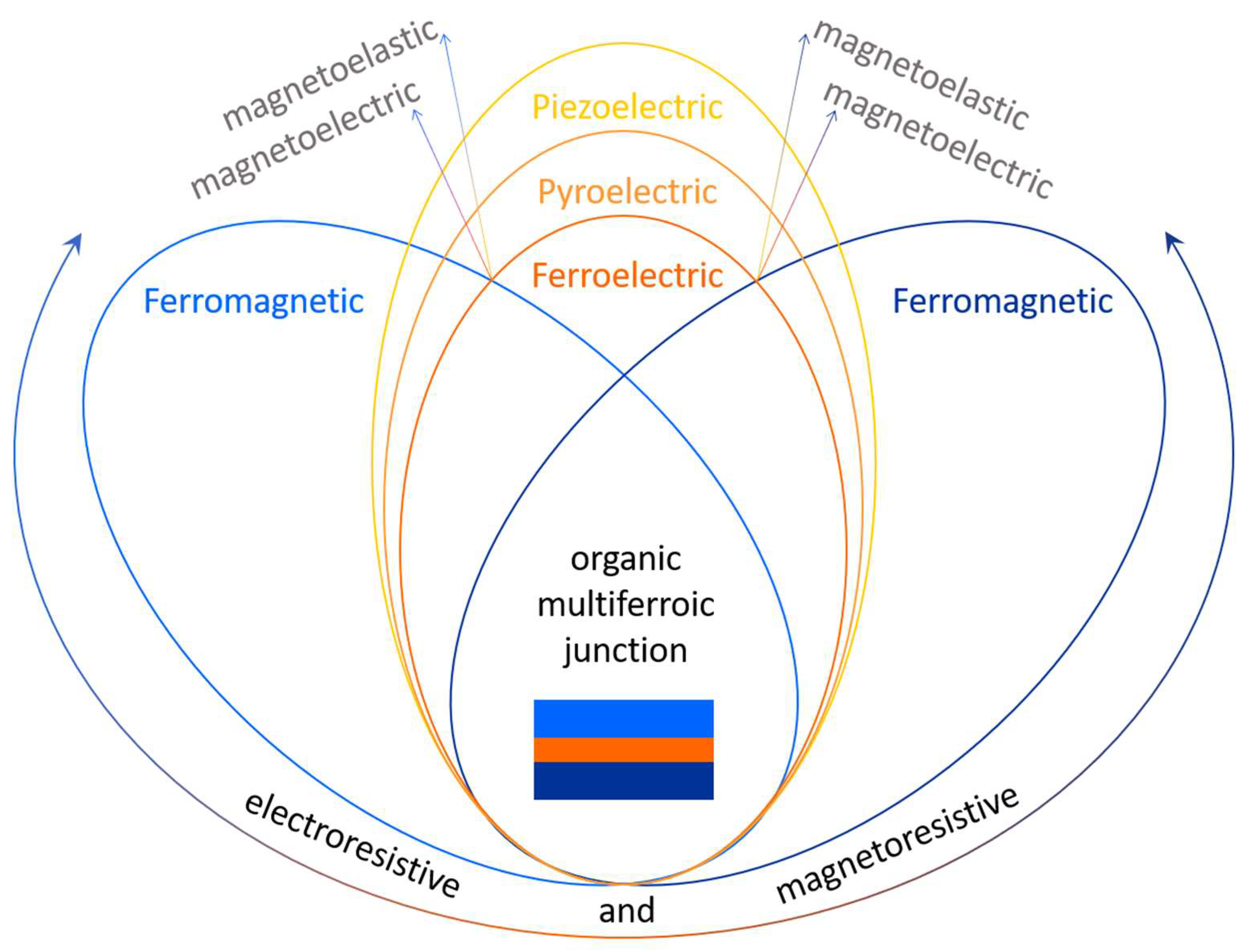
Figure 2.
A schematic representation of the magnetoresistance hysteretic behavior with the magnetic field for (a) positive MR and (b) negative MR, respectively.
Figure 2.
A schematic representation of the magnetoresistance hysteretic behavior with the magnetic field for (a) positive MR and (b) negative MR, respectively.
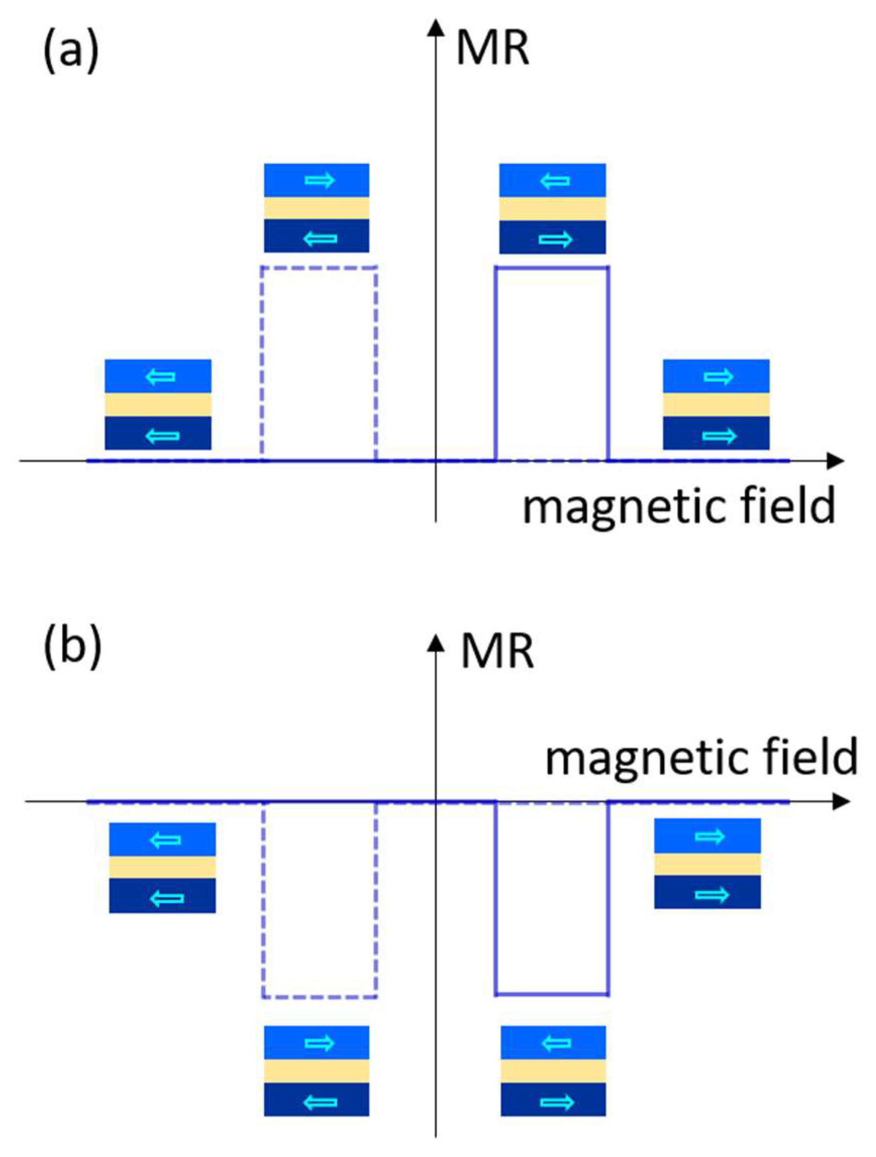
Figure 3.
A schematic representation of the charge carrier transport consisting of (a) electrons (e−) and (b) holes (h+) in metal–organic–metal junctions for an applied bias voltage ΔV, in function of the energy level alignment, where Ev is the vacuum level, EF is the Fermi level, φ1 and φ2 are the work functions of the two metals, LUMO and HOMO are the lowest unoccupied and the highest occupied molecular orbitals with an Eg energy gap between them and Ip and Ea are the ionization energy and the electron affinity energy, respectively.
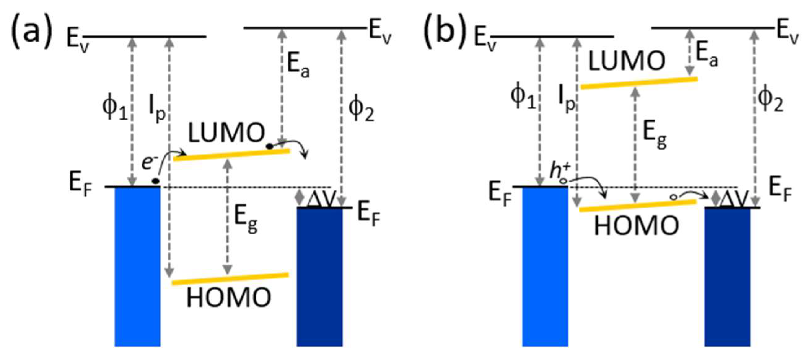
Figure 4.
A schematic representation of the charge distribution (a) and the electrostatic potential profile (b) in metal–ferroelectric–metal junctions for a polarization P and a depolarizing electric field E, where δ1 and δ2 are the screening distances in each metal electrode and ϕ1 and ϕ2 the corresponding electrostatic potentials. The dashed lines in panel (b) are related to the reversed orientation of the polarization P.
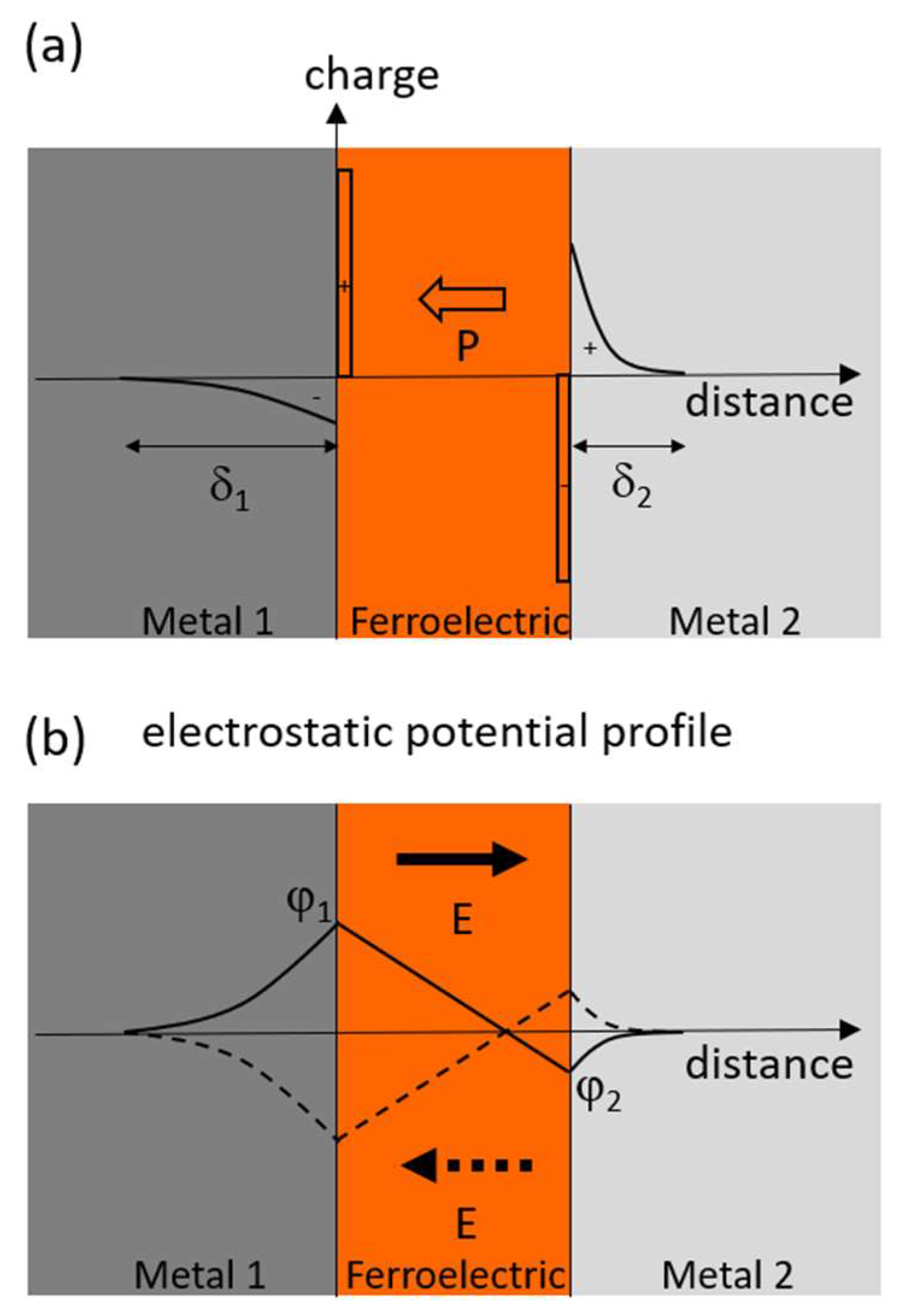
Figure 5.
A schematic representation of the asymmetric electronic potential with an average height εL and εR, respectively, in a metal–ferroelectric–metal junction for different orientations of the polarizations, PL (a) and PR (b), respectively, assuming that φ1 ≈ φ2 = φ and δ1 > δ2 (resulting ϕ1 > ϕ2).
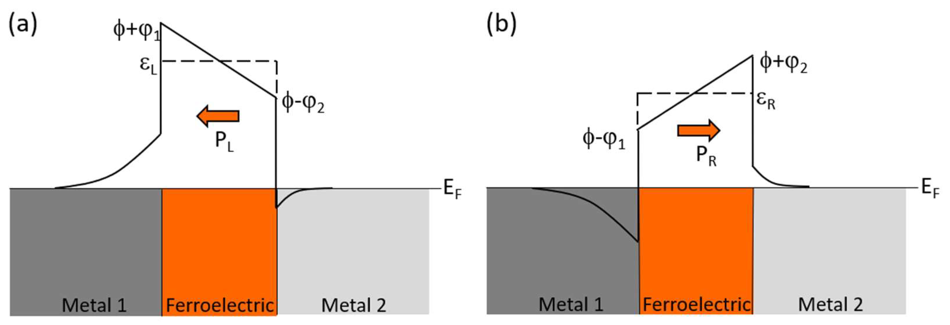
Figure 6.
MR and ER effects influenced by various factors such as interface, thickness and temperature on OMFJs containing PVDF in (a,b) Fe3O4/AlO/PVDF/Co (adapted with permission from Ref. [164]); (c,d) LSMO/PVDF/Co (adapted with permission from Ref. [165]); (e,f) LSMO/PVDF/Co and LSMO/PVDF/MgO/Co junctions (adapted with permission from Ref. [163]).
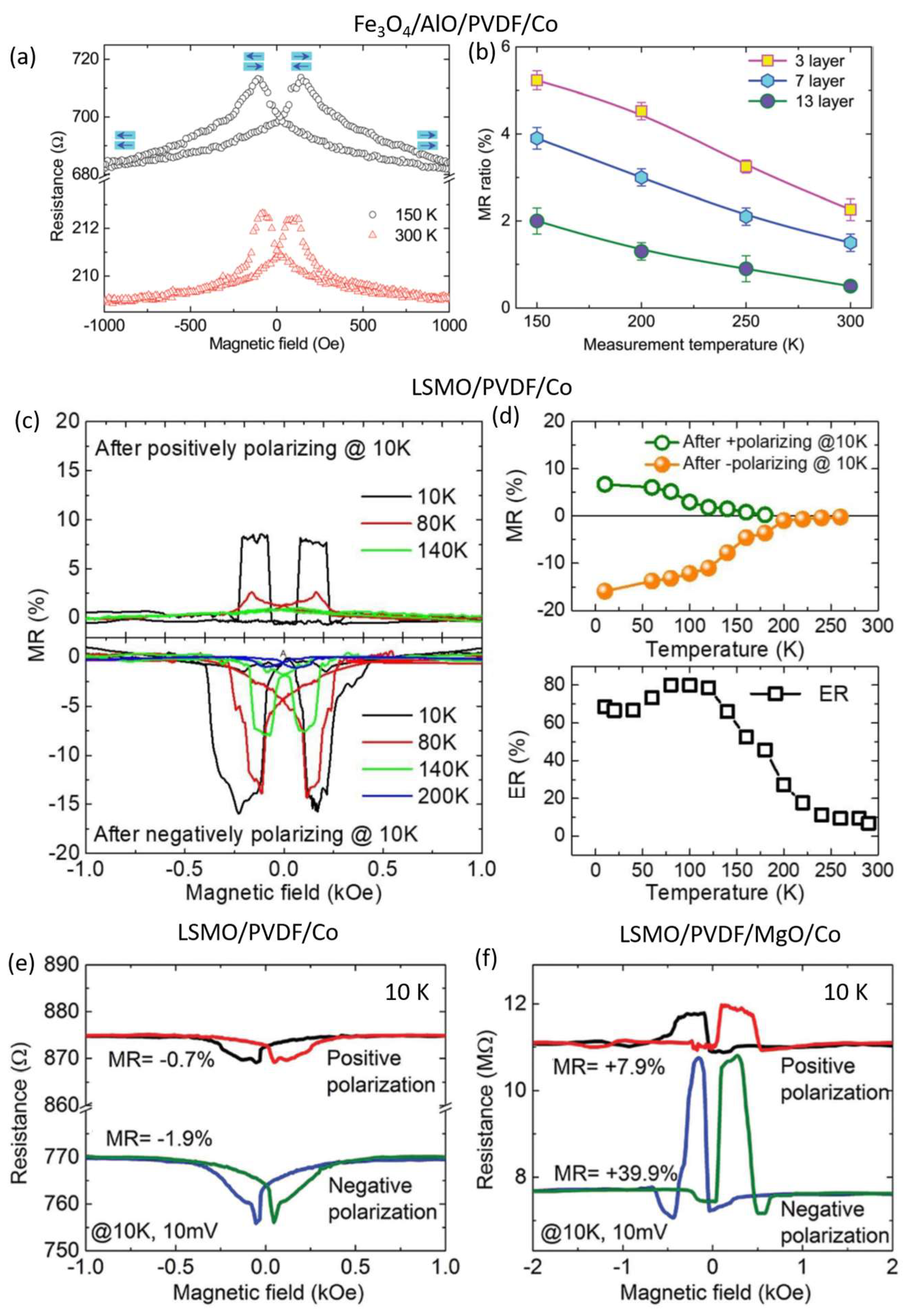
Figure 7.
MR and ER effects influenced by thickness, temperature and the applied electric field on OMFJs containing P(VDF-TrFE) films in LSMO/P(VDF-TrFE)/Co systems. (a–f) panels adapted with permission from Ref. [167]; (g–i) panels adapted with permission from Ref. [166].
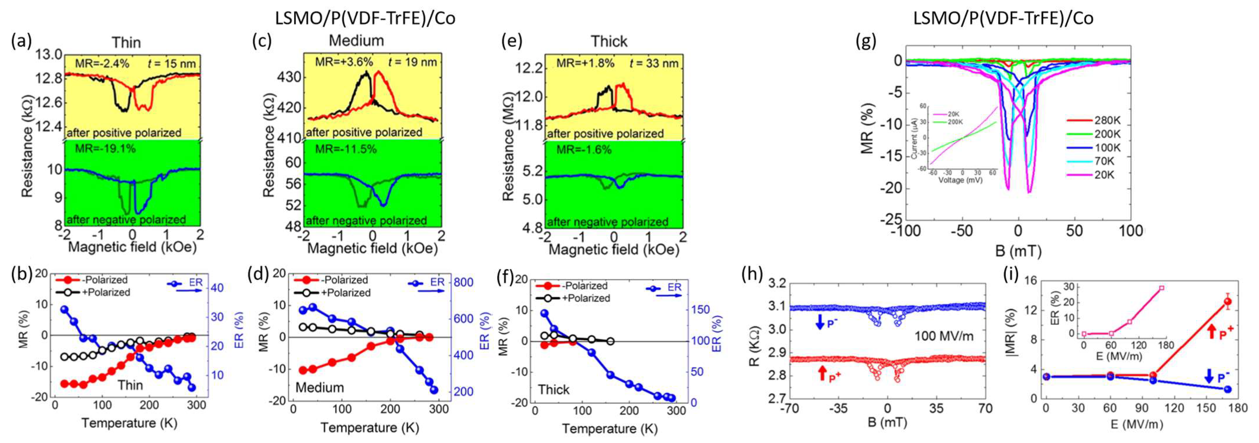
Figure 8.
MR and ER effects of a LSMO/croconic acid/SiO2/Co OMFJ influenced by the polarity and magnitude of the measurement voltage (a–c) and temperature (d). The figure was adapted with permission from Ref. [168].
Figure 8.
MR and ER effects of a LSMO/croconic acid/SiO2/Co OMFJ influenced by the polarity and magnitude of the measurement voltage (a–c) and temperature (d). The figure was adapted with permission from Ref. [168].
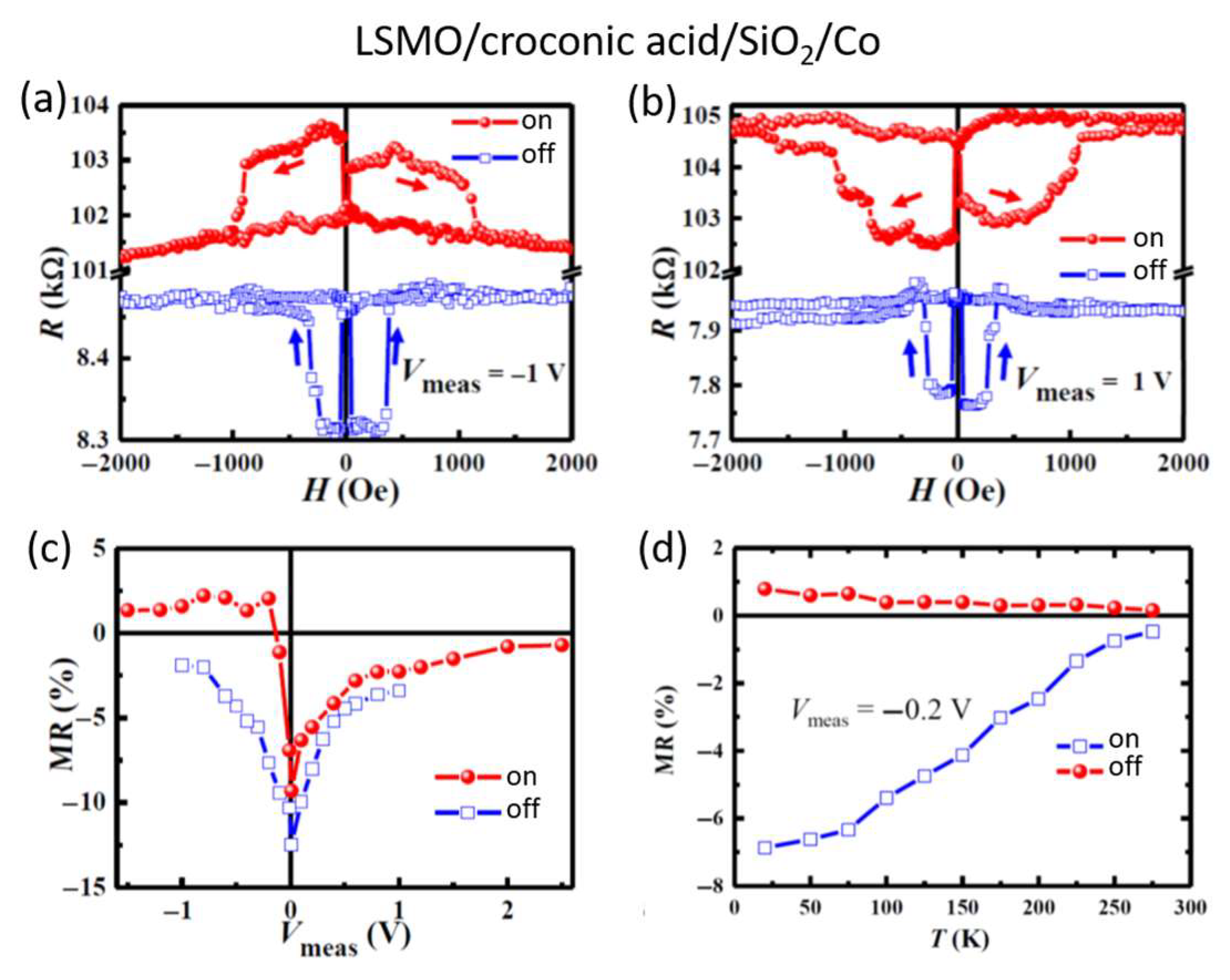

Table 1.
Organic spin valves. Abbreviations of molecule names are as follows: PC71BM—phenyl-C71-butyric-acid-metyl-ester; TCNE—tetracyanoethylene; BCP—buthocuproine; TPD—N,N-bis(3-methylphenyl)-N,N-diphenylbenzidine; BTQBT—bis(l,2,5-thiadiazolo)-P-quinobis(l,3-dithiole); TIPS-pentacene—6,13-bis(triisopropylsilylethynyl)-pentacene; DOO-PPV—poly(dioctyloxy)phenylenevinylene; Alq3—tris(8-hydroxyquinolinato)aluminum; Gaq3—tris-(8-hydroxyquinoline)gallium; IC12H2(PO3Et2)2—diethyl(11-iodoundecyl)phosphonate; Tb[Pc(C12OPO3Et2)]2—terbium bis-phthalocyaninato-diethyl-phosphonate; NitPO—4-methylbenzylphosphonate)-4,4,5,5-tetramethylimidazoline-1-oxyl-3-oxide; P3HT—poly(3-hexylthiophene); F4TCNQ—2,3,5,6-Tetrafluoro-7,7,8,8-tetracyanoquinodimethane; P3MT—poly(3-methylthiophene); T6—sexithienyl; CVB—4,4′-bis99-(ethyl-3-carbazovinylene)-1,1′-bipheny; C8-BTBT—2,7-dioctyl [1]benzothieno[3,2-b][1]benzothiophene; P(NDI2OD-T2)—poly{[N,N′-bis(2-octyldodecyl)-1,4,5,8-naphthalenedicarboximide)-2,6-diyl]-alt-5,5′-(2,2′-bithio-phene)}; F8BT—poly(9,9-dioctylfluorene-co-benzothidiazole); Py-Np—4,4′,4″,4′′′-(pyrene-1,3,6,8-tetrayl)tetraaniline-naphthalene-2,6-dicarbaldehyde; TPP—tetraphenyl porphyrin; H2Pc—hydrogen-phthalocyanine; CuPc—copper-phthalocyanine; FePc—iron-phthalocyanine; F16CuPc—fluorinated copper-phthalocyanine; and BDMT—1,4 benzenedimethanethiol.
| Organic Material | System (Thickness) | MR/Temp. (K) | Ref. |
|---|---|---|---|
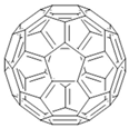 Fullerene | LSMO(50 nm)/C60(120 nm)/Co(15 nm) | −13.3%/20 K | [13] |
| LSMO(50 nm)/C60(180 nm)/Co(15 nm) | ~−7%/20 K | [13] | |
| LSMO(50 nm)/C60(180 nm)/Co(15 nm) | ~−4.5%/120 K | [13] | |
| LSMO(50 nm)/C60(180 nm)/Co(15 nm) | ~−1%/290 K | [13] | |
| Co(15 nm)/AlOx(1 nm)/C60(5 nm)/Py(20 nm) | 9%/300 K | [14] | |
| Co(15 nm)/AlOx(1 nm)/C60(28 nm)/Py(20 nm) | 5.5%/300 K | [14] | |
| Co(15 nm)/AlOx(1 nm)/C60(18 nm)/Py(20 nm) | ~14%/80 K | [14] | |
| Fe3O4/AlOx/C60(80 nm)/Co(10 nm) | 6.9%/150 K | [15] | |
| Fe3O4/AlOx/C60(80 nm)/Co(10 nm) | 5.3%/300 K | [15] | |
| Fe3O4/AlOx/C60(110 nm)/Co(10 nm) | ~2.2%/150 K | [15] | |
| Fe3O4/AlOx/C60(110 nm)/Co(10 nm) | ~0.5%/300 K | [15] | |
| LSMO(50 nm)/C70(120 nm)/Co(15 nm) | −8.9%/20 K | [13] | |
| LSMO(50 nm)/C70(180 nm)/Co(15 nm) | ~−6%/20 K | [13] | |
| LSMO(50 nm)/C70(180 nm)/Co(15 nm) | ~−4%/120 K | [13] | |
| LSMO(50 nm)/C70(180 nm)/Co(15 nm) | ~−0.8%/290 K | [13] | |
 PC71BM | Co(20 nm)/LiF(1.4 nm)/PC71BM(45 nm)/Py(12 nm) | ~6.2%/300 K | [16] |
| Co(20 nm)/LiF(1.5 nm)/PC71BM(45 nm)/Py(12 nm) | ~1.3%/300 K | [16] | |
| Co(20 nm)/LiF(1.6 nm)/PC71BM(45 nm)/Py(12 nm) | ~−0.6%/300 K | [16] | |
| Co(20 nm)/LiF(1.8 nm)/PC71BM(45 nm)/Py(12 nm) | ~−2.4%/300 K | [16] | |
| Co(20 nm)/LiF(2 nm)/PC71BM(45 nm)/Py(12 nm) | ~−1.2%/300 K | [16] | |
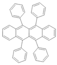 Rubrene | Fe3O4(100 nm)/AlOx(2 nm)/rubrene(2 nm)/Co(10 nm) | 6%/300 K | [17] |
| Fe3O4(100 nm)/AlOx(2 nm)/rubrene(2 nm)/Co(10 nm) | 11%/150 K | [17] | |
| Fe3O4(100 nm)/AlOx(2 nm)/rubrene(6 nm)/Co(10 nm) | 3.3%/300 K | [17] | |
| Fe3O4(100 nm)/AlOx(2 nm)/rubrene(6 nm)/Co(10 nm) | 9%/150 K | [17] | |
| Co(8 nm)/Al2O3(0.5 nm)/rubrene(4.6 nm)/Fe(10 nm)/CoO(1.5 nm) | 6%/295 K | [18] | |
| Co(8 nm)/Al2O3(0.5 nm)/rubrene(4.6 nm)/Fe(10 nm)/CoO(1.5 nm) | 13%/80 K | [18] | |
| Co(8 nm)/Al2O3(0.5 nm)/rubrene(4.6 nm)/Fe(10 nm)/CoO(1.5 nm) | 16%/4.2 K | [18] | |
| Co(15 nm)/AlOx(2.5 nm)/rubrene(5 nm)/Fe(15 nm) | ~−0.058%/100 K | [19] | |
| Co(15 nm)/AlOx(2.5 nm)/rubrene(10 nm)/Fe(15 nm) | ~−0.058%/100 K | [19] | |
| Co(15 nm)/AlOx(2.5 nm)/rubrene(5 nm)/Fe(15 nm) | ~−0.025%/300 K | [19] | |
| Co(15 nm)/AlOx(2.5 nm)/rubrene(10 nm)/Fe(15 nm) | ~−0.035%/300 K | [19] | |
| LSMO(50 nm)/LAO(1.2 nm)/rubrene(5 nm)/Fe(30 nm) | ~12.5%/10 K | [20] | |
| LSMO(50 nm)/LAO(1.2 nm)/rubrene(5 nm)/Fe(30 nm) | ~3.5%/150 K | [20] | |
| LSMO(50 nm)/LAO(1.2 nm)/rubrene(5 nm)/Fe(30 nm) | ~0.1%/250 K | [20] | |
| LSMO(50 nm)/LAO(1.2 nm)/rubrene(20 nm)/Fe(30 nm) | ~0.2%/10 K | [20] | |
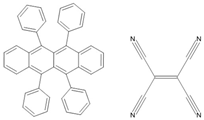 Rubrene/TCNE | Fe(50 nm)/rubrene(10 nm)/V[TCNE]x(300 nm) | −0.06%/100 K | [21] |
| Fe(50 nm)/rubrene(10 nm)/V[TCNE]x(300 nm) | −0.02%/200 K | [21] | |
| Fe(50 nm)/rubrene(10 nm)/V[TCNE]x(300 nm) | 0.01%/300 K | [21] | |
| Al(50 nm)/V[TCNE]x(50 nm)/rubrene(10 nm)/V[TCNE]x(300 nm)/Al(30 nm) | −0.035%/100 K | [22] | |
| Al(50 nm)/V[TCNE]x(50 nm)/rubrene(10 nm)/V[TCNE]x(300 nm)/Al(30 nm) | −0.01%/200 K | [22] | |
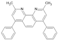 BCP | Co(11 nm)/AlOx(1.5 nm)/BCP(5 nm)/Py(11 nm) | ~4.5%/300 K | [23] |
| Co(11 nm)/AlOx(1.5 nm)/BCP(10 nm)/Py(11 nm) | ~4%/300 K | [23] | |
| Co(11 nm)/AlOx(1.5 nm)/BCP(30 nm)/Py(11 nm) | ~4%/300 K | [23] | |
| Co(11 nm)/AlOx(1.5 nm)/BCP(10 nm)/Py(11 nm) bending/in air | ~3%/300 K | [24] | |
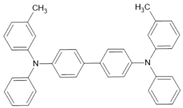 TPD | Co2MnSi(20 nm)/TPD(200 nm)/Co(7 nm) | 7.8%/300 K | [25] |
| Co2MnSi(20 nm)/TPD(200 nm)/Co(7 nm) | ~11%/150 K | [25] | |
| Co2MnSi(20 nm)/TPD(200 nm)/Co(7 nm) | 10.7%/5 K | [25] | |
| LSMO/TPD(200 nm)/Co(7 nm) | ~1.5%/250 K | [25] | |
| LSMO/TPD(200 nm)/Co(7 nm) | ~5%/150 K | [25] | |
| LSMO/TPD(200 nm)/Co(7 nm) | 19%/5 K | [25] | |
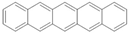 pentacene | LSMO/pentacene(200 nm)/LSMO | ~5.5%/5.3 K | [26] |
| LSMO/pentacene(30 nm)/LSMO | ~2%/9 K | [27] | |
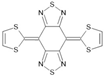 BTQBT | LSMO/BTQBT(200 nm)/LSMO | ~8%/10 K | [26] |
| LSMO/BTQBT(50 nm)/LSMO | ~28%/9.1 K | [26] | |
 TIPS-Pentacene | CoPt(10 nm)/TIPS-pentacene(75 nm)/AlOx(2 nm)/Co(10 nm) | −0.08%/300 K | [28] |
| CoPt(10 nm)/TIPS-pentacene(40 nm)/AlOx(2 nm)/Co(10 nm) | ~−0.45%/300 K | [28] | |
| CoPt(10 nm)/TIPS-pentacene(40 nm)/AlOx(2 nm)/Co(10 nm) | ~−0.05%/175 K | [28] | |
| CoPt(10 nm)/TIPS-pentacene(100 nm)/AlOx(2 nm)/Co(10 nm) | ~−0.05%/300 K | [28] | |
| LSMO/TIPS-pentacene single crystal(269 nm)/Co(10 nm) | ~−17%/30 K | [28] | |
| LSMO/TIPS-pentacene single crystal(457 nm)/Co(10 nm) | ~−1.5%/30 K | [29] | |
| LSMO/TIPS-pentacene single crystal(269 nm)/Co(10 nm) | ~−2.8%/100 K | [29] | |
| LSMO/TIPS-pentacene polycryst. film(97 nm)/Co(10 nm) | ~−6%/30 K | [29] | |
| LSMO/TIPS-pentacene polycryst. film(97 nm)/Co(10 nm) | ~−3.5%/100 K | [29] | |
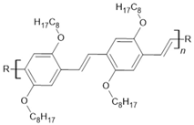 DOO-PPV | LSMO(200 nm)/Hydrogen-DOO-PPV(25 nm)/Co(15 nm) | 2%/10 K | [30] |
| LSMO(200 nm)/Deuterium-DOO-PPV(25 nm)/Co(15 nm) | ~40%/10 K | [30] | |
| LSMO(200 nm)/H/D-DOO-PPV(25 nm)/Co(15 nm) | ~5%/10 K | [30] | |
| LSMO(200 nm)/H/D-DOO-PPV(25 nm)/Co(15 nm) | ~2.5%/150 K | [30] | |
| LSMO(200 nm)/H/D-DOO-PPV(25 nm)/Co(15 nm) | ~0.2%/300 K | [30] | |
| LSMO(200 nm)/H-DOO-PPV(55 nm)/Co(15 nm) | ~0.2%/10 K | [30] | |
| LSMO(200 nm)/D-DOO-PPV(55 nm)/Co(15 nm) | ~2.5%/10 K | [30] | |
 Alq3 | LSMO(100 nm)/Alq3(130 nm)/Co(3.5 nm) | −40%/11 K | [31] |
| LSMO(100 nm)/Alq3(160 nm)/Co(3.5 nm) | ~−14%/11 K | [31] | |
| LSMO(100 nm)/Alq3(200 nm)/Co(3.5 nm) | ~−7%/11 K | [31] | |
| LSMO(100 nm)/Alq3(250 nm)/Co(3.5 nm) | ~−2%/11 K | [31] | |
| LSMO(100 nm)/Alq3(160 nm)/Co(3.5 nm) | ~−2%/130 K | [31] | |
| LSMO(100 nm)/Alq3(160 nm)/Co(3.5 nm) | ~−0.3%/230 K | [31] | |
| Co(8 nm)/Al2O3(0.6 nm)/Alq3(1.6 nm)/Py(10 nm) | 4.6%/300 K | [32] | |
| Co(8 nm)/Al2O3(0.6 nm)/Alq3(1.6 nm)/Py(10 nm) | 6.8%/77 K | [32] | |
| Co(8 nm)/Al2O3(0.6 nm)/Alq3(1.6 nm)/Py(10 nm) | 7.5%/4.2 K | [32] | |
| LSMO(15–20 nm)/Alq3 (300 nm)/Al2O3 (2 nm)/Co(35 nm) | ~−0.1%/20 K | [33] | |
| LSMO(15–20 nm)/Alq3 (200 nm)/Al2O3 (2 nm)/Co(35 nm) | ~−5%/20 K | [33] | |
| LSMO(15–20 nm)/Alq3 (100 nm)/Al2O3 (2 nm)/Co(35 nm) | −11%/20 K | [33] | |
| LSMO(15–20 nm)/Alq3 (100 nm)/Al2O3 (2 nm)/Co(35 nm) | −6%/100 K | [33] | |
| LSMO(15–20 nm)/Alq3 (100 nm)/Al2O3 (2 nm)/Co(35 nm) | −0.15%/300 K | [33] | |
| LSMO/Alq3 (23 nm)/Co-nanodots/Co(7 nm) | −1%/10 K | [34] | |
| LSMO/Alq3 (67 nm)/Co-nanodots/Co(7 nm) | −7%/10 K | [34] | |
| LSMO/Alq3 (93 nm)/Co-nanodots/Co(7 nm) | −300%/10 K | [34] | |
| LSMO/Alq3 (135 nm)/Co-nanodots/Co(7 nm) | −13%/10 K | [34] | |
| LSMO/Alq3 (93 nm)/Co(7 nm) | −35%/10 K | [34] | |
| LSMO/Alq3 (135 nm)/Co(7 nm) | −4%10 K | [34] | |
| LSMO/Alq3 (40 nm)/Co(20 nm) | ~−18%/100 K | [35] | |
| LSMO/Alq3 (40 nm)/Co(20 nm) | ~−10%/150 K | [35] | |
| LSMO/Alq3 (40 nm)/Co(20 nm) | −0.07%/300 K | [35] | |
| LPCMO(60 nm)/Alq3(60 nm)/Co(10 nm) | 100–440%(1−7T)/10 K | [36] | |
| LPCMO(60 nm)/Alq3(60 nm)/Co(10 nm) | ~200%(7T)/25 K | [36] | |
| LPCMO(60 nm)/Alq3(60 nm)/Co(10 nm) | ~100%(7T)/75 K | [36] | |
| LPCMO(60 nm)/Alq3(60 nm)/Co(10 nm) | ~1%(7T)/150 K | [36] | |
| LSMO/Alq3(60 nm)/Co(10 nm) | −37%/10 K | [36] | |
| SFMO(150 nm)/Alq3(45 nm)/Co(16 nm) | 30%/10 K | [37] | |
| SFMO(150 nm)/Alq3(45 nm)/Co(16 nm) | 25%/100 K | [37] | |
| SFMO(150 nm)/Alq3(45 nm)/Co(16 nm) | 10%/200 K | [37] | |
| SFMO(150 nm)/Alq3(45 nm)/Co(16 nm) | 2%/300 K | [37] | |
| Fe3O4(110 nm)/AlOx(2 nm)/Alq3(2 nm)/Co(10 nm) | ~12.5%/150 K | [38] | |
| Fe3O4(110 nm)/AlOx(2 nm)/Alq3(2 nm)/Co(10 nm) | ~6%/300 K | [38] | |
| Fe3O4(110 nm)/AlOx(2 nm)/Alq3(10 nm)/Co(10 nm) | ~4%/150 K | [38] | |
| Fe3O4(110 nm)/AlOx(2 nm)/Alq3(10 nm)/Co(10 nm) | ~2%/300 K | [38] | |
| Fe3O4(110 nm)/AlOx(2 nm)/Alq3(20 nm)/Co(10 nm) | ~1%/150 K | [38] | |
| Fe3O4(110 nm)/AlOx(2 nm)/Alq3(20 nm)/Co(10 nm) | ~0.5%/300 K | [38] | |
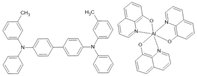 TPD/Alq3 | FeCo(17 nm)/TPD(50 nm)/Alq3(200 nm)/LiF(1.9 nm)/NiFe(17 nm) | ~0.3%/40 K | [39] |
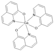 Gaq3 | LSMO(20 nm)/Gaq3 (10–15 nm)/AlOx(2 nm)/Co(7 nm) electrically controlled-high-resistive state (oxygen migration) | −2%/100 K | [40] |
| LSMO(20 nm)/Gaq3 (10–15 nm)/AlOx(2 nm)/Co(7 nm) electrically controlled-high-resistive state (oxygen migration) | −8%/100 K | [40] | |
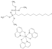 IC12H2(PO3Et2)2/ Gaq3 | LSMO/IC12H2(PO3Et2)2(ML)/Gaq3(40 nm)/AlOx(2 nm)/Co | ~−1.9%/200 K | [41] |
| LSMO/IC12H2(PO3Et2)2(ML)/Gaq3(40 nm)/ AlOx(2 nm)/Co | ~−9.8%/100 K | [41] | |
| LSMO/IC12H2(PO3Et2)2(ML)/Gaq3(40 nm)/ AlOx(2 nm)/Co | ~−18%/10 K | [41] | |
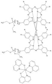 Tb[Pc(C12OPO3Et2)]2 /Gaq3 | LSMO/Tb[Pc(C12OPO3Et2)]2(ML)/Gaq3(40 nm)/AlOx(2 nm)/Co | ~−2%/200 K | [41] |
| LSMO/Tb[Pc(C12OPO3Et2)]2(ML)/Gaq3(40 nm)/AlOx(2 nm)/Co | ~−9.3%/100 K | [41] | |
| LSMO/Tb[Pc(C12OPO3Et2)]2(ML)/Gaq3(40 nm)/AlOx(2 nm)/Co | ~−13%/100 K | [41] | |
 NitPO/Gaq3 | LSMO(15 nm)/NitPO(ML)/Gaq3(150 nm)/AlOx(2 nm)/Co | −4.34%/100 K | [42] |
| LSMO(15 nm)/NitPO(ML)/Gaq3(150 nm)/AlOx(2 nm)/Co | −7.1%/3 K | [42] | |
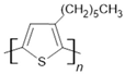 P3HT | Fe50Co50(20 nm)/P3HT(75 nm)/Ni81Fe19(20 nm) | 0.1%/300 K | [43] |
| Fe50Co50(40 nm)/P3HT(150 nm)/Ni81Fe19(20 nm) | −0.04%/300 K | [43] | |
| Ni81Fe19(12 nm)/P3HT(30 nm)/AlOx(1 nm)/Co(10 nm) | ~1%/10 K | [44] | |
| Fe3O4(80 nm)/P3HT(12 nm)/AlOx(1 nm)/Co(12 nm) | ~2.3%/100 K | [45] | |
| Fe3O4(80 nm)/P3HT(12 nm)/AlOx(1 nm)/Co(12 nm) | ~0.75%/200 K | [45] | |
| Fe3O4(80 nm)/P3HT(25 nm)/AlOx(1 nm)/Co(12 nm) | ~1.75%/100 K | [45] | |
| LSMO/P3HT(100 nm)/Co(10 nm) | 80%/5 K | [46] | |
| LSMO/P3HT(100 nm)/Co(10 nm) | 1.5%/300 K | [46] | |
| LSMO(100 nm)/P3HT(80 nm)/AlOx(1 nm)/Co(10 nm) | −0.2%/2 K 15.6%/2 K | [47] | |
| LSMO/P3HTannealed(45 nm)/Co | ~15%/20 K | [48] | |
| LSMO/P3HTannealed(72 nm)/Co | ~11%/20 K | [48] | |
| LSMO/P3HTannealed(103 nm)/Co | ~8%/20 K | [48] | |
| LSMO/P3HTannealed(175 nm)/Co | ~4%/20 K | [48] | |
| LSMO/P3HT(45 nm)/Co | ~12%/20 K | [48] | |
| LSMO/P3HT(72 nm)/Co | ~6%/20 K | [48] | |
| LSMO/P3HT(103 nm)/Co | ~3%/20 K | [48] | |
| LSMO/P3HT(175 nm)/Co | ~2%/20 K | [48] | |
| LPCMO(60 nm)/P3HT(30 nm)/AlOx/Co(10 nm) | 93%/30 K | [49] | |
| LPCMO(60 nm)/P3HT(30 nm)/AlOx/Co(10 nm) | ~53%/50 K | [49] | |
| LPCMO(60 nm)/P3HT(30 nm)/AlOx/Co(10 nm) | ~30%/75 K | [49] | |
| LSMO(100 nm)/P3HT(20 nm)/AlOx(1 nm)/Co(10 nm) | ~7.5%/2 K | [50] | |
| LSMO(100 nm)/P3HT(20 nm)/AlOx(1 nm)/Co(10 nm) | ~4%/5 K | [50] | |
| LSMO(100 nm)/P3HT(20 nm)/AlOx(1 nm)/Co(10 nm) | ~3%/10 K | [50] | |
| LSMO(100 nm)/P3HT(20 nm)/AlOx(1 nm)/Co(10 nm) | ~0.1%/30 K | [50] | |
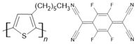 P3HT/F4-TCNQ | LSMO(100 nm)/P3HT(40 nm)/F4TCNQ dopant/Co(15 nm) | ~19%/2 K | [51] |
| LSMO(100 nm)/P3HT(40 nm)/F4TCNQ dopant/Co(15 nm) | ~16%/5 K | [51] | |
| LSMO(100 nm)/P3HT(40 nm)/F4TCNQ dopant/Co(15 nm) | ~14%/10 K | [51] | |
| LSMO(100 nm)/P3HT(40 nm)/F4TCNQ dopant/Co(15 nm) | ~13%/15 K | [51] | |
| LSMO(100 nm)/P3HT(40 nm)/F4TCNQ dopant/Co(15 nm) | ~11%/20 K | [51] | |
 P3MT | LSMO/P3MT(15 nm)/Co(15 nm) | ~−43%/20 K | [52] |
| LSMO/P3MT(15 nm)/Co(15 nm) | ~−0.3%/280 K | [52] | |
 T6 | LSMO/T6(70–140 nm)/LSMO | 15–30%/300 K | [9] |
| LSMO/T6(200 nm)/LSMO | 7–10%/300 K | [9] | |
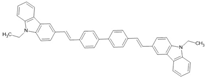 CVB | LSMO/CVB(100 nm)/Co | ~−15%/14 K | [53] |
| LSMO/CVB(100 nm)/Co | ~−3.5%/140 K | [53] | |
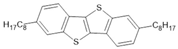 C8-BTBT | Ni78Fe22/C8-BTBT(2 nm)/Ni78Fe22 | ~−0.3%/300 K | [54] |
| Ni78Fe22/C8-BTBT(4 nm)/Ni78Fe22 | ~0.5%/300 K | [54] | |
| Py/C8-BTBT(1ML)/Co | ~−1%/10 K | [55] | |
| Py/C8-BTBT(2ML)/Co | ~−12%/10 K | [55] | |
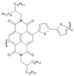 P(NDI2OD-T2) | LSMO(100 nm)/P(NDI2OD-T2)(35 nm)/AlOx(1.5 nm)/Co(10 nm) | ~30%/4.2 K | [56] |
| LSMO(100 nm)/P(NDI2OD-T2)(35 nm)/AlOx(1.5 nm)/Co(10 nm) | ~18%/50 K | [56] | |
| LSMO(100 nm)/P(NDI2OD-T2)(35 nm)/AlOx(1.5 nm)/Co(10 nm) | ~5%/150 K | [56] | |
| LSMO(100 nm)/P(NDI2OD-T2)(35 nm)/AlOx(1.5 nm)/Co(10 nm) | ~1%/250 K | [56] | |
| LSMO(100 nm)/P(NDI2OD-T2)(100 nm)/AlOx(1.5 nm)/Co(10 nm) | ~10%/4.2 K | [56] | |
| LSMO(100 nm)/P(NDI2OD-T2)(100 nm)/AlOx(1.5 nm)/Co(10 nm) | ~5%/50 K | [56] | |
| LSMO(100 nm)/P(NDI2OD-T2)(100 nm)/AlOx(1.5 nm)/Co(10 nm) | ~2%/150 K | [56] | |
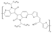 PIID-CNTVT-C1: X=C PAIID-CNTVT-C1: X=N | LSMO(50 nm)/PIID-CNTVT-C1(40 nm)/Py(10 nm) | ~19%/50 K | [57] |
| LSMO(50 nm)/PIID-CNTVT-C1(40 nm)/Py(10 nm) | ~14%/100 K | [57] | |
| LSMO(50 nm)/PIID-CNTVT-C1(40 nm)/Py(10 nm) | ~8%/150 K | [57] | |
| LSMO(50 nm)/PIID-CNTVT-C1(40 nm)/Py(10 nm) | ~3%/200 K | [57] | |
| LSMO(50 nm)/PAIID-CNTVT-C1(40 nm)/Py(10 nm) | ~25%/50 K | [57] | |
| LSMO(50 nm)/PAIID-CNTVT-C1(40 nm)/Py(10 nm) | ~17%/100 K | [57] | |
| LSMO(50 nm)/PAIID-CNTVT-C1(40 nm)/Py(10 nm) | ~10%/150 K | [57] | |
| LSMO(50 nm)/PAIID-CNTVT-C1(40 nm)/Py(10 nm) | ~5%/200 K | [57] | |
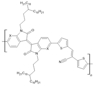 PIID-CNTVT-C3: X=C-H PAIID-CNTVT-C3: X=N | LSMO(50 nm)/PIID-CNTVT-C3(40 nm)/Py(10 nm) | ~16%/50 K | [57] |
| LSMO(50 nm)/PIID-CNTVT-C3(40 nm)/Py(10 nm) | ~12%/100 K | [57] | |
| LSMO(50 nm)/PIID-CNTVT-C3(40 nm)/Py(10 nm) | ~6%/150 K | [57] | |
| LSMO(50 nm)/PIID-CNTVT-C3(40 nm)/Py(10 nm) | ~2%/200 K | [57] | |
| LSMO(50 nm)/PAIID-CNTVT-C3(40 nm)/Py(10 nm) | ~23%/50 K | [57] | |
| LSMO(50 nm)/PAIID-CNTVT-C3(40 nm)/Py(10 nm) | ~15%/100 K | [57] | |
| LSMO(50 nm)/PAIID-CNTVT-C3(40 nm)/Py(10 nm) | ~10%/150 K | [57] | |
| LSMO(50 nm)/PAIID-CNTVT-C3(40 nm)/Py(10 nm) | ~5%/200 K | [57] | |
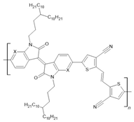 PIID-TVTCN: X=C-H PAIID-TVTCN: X=N PFIID-TVTCN: X=C-F | LSMO(30 nm)/PIID-TVTCN(25 nm)/Co(10 nm) | ~−23%/50 K | [58] |
| LSMO(30 nm)/PIID-TVTCN(25 nm)/Co(10 nm) | ~−8%/200 K | [58] | |
| LSMO(30 nm)/PAIID-TVTCN(25 nm)/Co(10 nm) | ~−10%/50 K | [58] | |
| LSMO(30 nm)/PAIID-TVTCN(25 nm)/Co(10 nm) | ~−3%/200 K | [58] | |
| LSMO(30 nm)/PFIID-TVTCN(25 nm)/Co(10 nm) | ~−16%/50 K | [58] | |
| LSMO(30 nm)/PFIID-TVTCN(25 nm)/Co(10 nm) | ~−5%/200 K | [58] | |
| LSMO(30 nm)/PIID-TVTCN(25 nm)/AlOx(2 nm)/Co(10 nm) | ~10%/50 K | [58] | |
| LSMO(30 nm)/PIID-TVTCN(25 nm)/AlOx(2 nm)/Co(10 nm) | ~4%/200 K | [58] | |
| LSMO(30 nm)/PAIID-TVTCN(25 nm)/AlOx(2 nm)/Co(10 nm) | ~17%/50 K | [58] | |
| LSMO(30 nm)/PAIID-TVTCN(25 nm)/AlOx(2 nm)/Co(10 nm) | ~5%/200 K | [58] | |
| LSMO(30 nm)/PFIID-TVTCN(25 nm)/AlOx(2 nm)/Co(10 nm) | ~10%/50 K | [58] | |
| LSMO(30 nm)/PFIID-TVTCN(25 nm)/AlOx(2 nm)/Co(10 nm) | ~3%/200 K | [58] | |
 PNVT-8: X=H PNVT-CN-8:X=CN | NiFe(12 nm)/PNVT-8(15 nm)/Co(12 nm) | ~0.35%/10 K | [59] |
| NiFe(12 nm)/PNVT-8(15 nm)/Co(12 nm) | ~0.18/150 K | [59] | |
| NiFe(12 nm)/PNVT-8(15 nm)/Co(12 nm) | ~0.12/300 K | [59] | |
| NiFe(12 nm)/PNVT-CN-8(15 nm)/Co(12 nm) | ~0.22/10 K | [59] | |
| NiFe(12 nm)/PNVT-CN-8(15 nm)/Co(12 nm) | ~0.1%/150 K | [59] | |
| NiFe(12 nm)/PNVT-CN-8(15 nm)/Co(12 nm) | ~0.08%/300 K | [59] | |
| NiFe(12 nm)/Au(3 nm)/PNVT-CN-8(25 nm)/Co(12 nm) | ~−0.1%/100 K | [60] | |
| NiFe(12 nm)/Au(3 nm)/PNVT-CN-8(25 nm)/Co(12 nm) | ~−0.08%/300 K | [60] | |
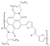 PNVT-10: X=H PNVT-CN-10:X=CN | NiFe(12 nm)/PNVT-10(15 nm)/Co(12 nm) | ~0.19%/10 K | [59] |
| NiFe(12 nm)/PNVT-10(15 nm)/Co(12 nm) | ~0.07/150 K | [59] | |
| NiFe(12 nm)/PNVT-10(15 nm)/Co(12 nm) | ~0.02/300 K | [59] | |
| NiFe(12 nm)/PNVT-CN-10(15 nm)/Co(12 nm) | ~0.13%/10 K | [59] | |
| NiFe(12 nm)/PNVT-CN-10(15 nm)/Co(12 nm) | ~0.05/150 K | [59] | |
| NiFe(12 nm)/PNVT-CN-10(15 nm)/Co(12 nm) | ~0.02/200 K | [59] | |
| NiFe(12 nm)/Au(3 nm)/PNVT-CN-10(25 nm)/Co(12 nm) | ~0.05%/10 K | [60] | |
| NiFe(12 nm)/Au(3 nm)/PNVT-CN-10(25 nm)/Co(12 nm) | ~−0.03%/100 K | [60] | |
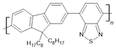 F8BT | LSMO(20 nm)/F8BT(45 nm)/MoOx(3 nm)/Co(20 nm) magneto-electroluminescence | ~9%/20 K ~2.4%/20 K | [61] |
| LSMO(20 nm)/F8BT(45 nm)/MoOx(3 nm)/Co(20 nm) | ~7%/30 K | [61] | |
| LSMO(20 nm)/F8BT(45 nm)/MoOx(3 nm)/Co(20 nm) magneto-electroluminescence | ~3%/100 K ~0.4%/100 K | [61] | |
| LSMO(20 nm)/F8BT(45 nm)/MoOx(3 nm)/Co(20 nm) | ~1%/150 K | [61] | |
 Py-Np | LSMO/Py-Np(90 nm)/Co(20 nm) | ~−27%/30 K | [62] |
| LSMO/Py-Np(90 nm)/Co(20 nm) | ~−19%/100 K | [62] | |
| LSMO/Py-Np(90 nm)/Co(20 nm) | ~−9%/150 K | [62] | |
| LSMO/Py-Np(90 nm)/Co(20 nm) | ~−2%/200 K | [62] | |
 TPP | LSMO(50 nm)/TPP(20 nm)/Co(5 nm) | ~−15%/80 K | [63] |
| LSMO(50 nm)/TPP(20 nm)/Co(5 nm) | ~−6%/80 K | [63] | |
| LSMO(50 nm)/TPP(20 nm)/Co(5 nm) | ~−3%/80 K | [63] | |
 H2Pc | Co(12 nm)/AlOx(1.5 nm)/H2Pc(90 nm)/Py spin-photovoltaic-resistive levels control with light intensity | ~7%/300 K | [64] |
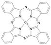 CuPc | Fe(25 nm)/CuPc(100 nm)/Co(5 nm) | 6.4%/40 K | [65] |
| Fe(25 nm)/CuPc(100 nm)/Co(5 nm) | 3.2%/80 K | [65] | |
| Fe(25 nm)/CuPc(100 nm)/Co(5 nm) | 1.8%/120 K | [65] | |
| LSMO/CuPc(110 nm)/Co | ~−6%/10 K | [66] | |
| LSMO/CuPc(110 nm)/Co | ~−4.5%/110 K | [66] | |
| LSMO/CuPc(110 nm)/Co | ~−1%/300 K | [66] | |
| LSMO/CuPc(50 nm)/Co | ~−20%/10 K | [66] | |
| LSMO/CuPc(160 nm)/Co | ~−2.5%/10 K | [66] | |
| LSMO/CuPc(200 nm)/Co | ~−0.5%/10 K | [66] | |
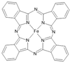 FePc | Co/FePc(50 nm)/Co | 4%/10 K | [67] |
| Co/FePc(50 nm)/Co | 1.2%/50 K | [67] | |
| Co/FePc(50 nm)/Co | 0.5%/100 K | [67] | |
 F16CuPc | Co/AlOx/F16CuPc(15 nm)/Py | ~4%/300 K | [68] |
| Co/AlOx/F16CuPc(90 nm)/Py Spin-photovoltaic (vacuum or air) | ~4%/295 K −30/−25%/295 K | [68] | |
 BDMT | NiFe(15 nm)/FeCo(10 nm)/BDMT(1 nm)/AlOx(1 nm)FeCo(35 nm) | 2.4%/20 K | [69] |
| NiFe(15 nm)/FeCo(10 nm)/BDMT(1 nm)/AlOx(1 nm)/FeCo(35 nm) | 1.9%/100 K | [69] | |
| NiFe(15 nm)/FeCo(10 nm)/BDMT(1 nm)/AlOx(1 nm)/FeCo(35 nm) | 0.25%/300 K | [69] |
Table 2.
Organic ferroelectrics. Abbreviations of molecule names are as follows: TCAA—trichloroacetamide; TEMPO or tanane—tetramethyl-2,2,6,6-piperidinyl-oxyle; CDA—cyclohexan-1,1′-diacetic acid; TCHM—tricyclohexylmethanol; DNP—1,6-bis(2,4-dinitrophenoxy)-2,4-hexadiyne; CBDC—cyclobutene-1,2-dicarboxylic acid; PhMDA—2-phenylmalondialdehyde; 3-HPLN—3-hydroxyphenalenone; MBI—2-methylbenzimidazole; DC-MBI—5,6-dichloro-2-methylbenzimidazole; 1P—2-(p-tolyl)-1H-phenanthro[9,10-d]imidazole; SF-PFA—N-salicylidene-2,3,4,5,6-pentafluoroaniline; FF—diphenylalanine; PVDF—poly(vinylidene fluoride); P(VDF-TrFE)—poly(vinylidene fluoride—trifluoroethylene); P(VDF-HFP)—poly(vinylidene fluoride-hexafluoropropylene); TTF/CA—tetrathiafulvalene/chloranil; TTF/BA—tetrathiafulvalene/bromanil; Phz/H2ca—phenazine/2,5-dicloro-3,6-dihydroxy-p-benzoquinones; Phz/H2ba—phenazine/2,5-dibromo-3,6-dihydroxy-p-benzoquinones; DMBP/H2ia—5,5′-dimethyl-2,2′-bipyridine/2,5-diiodo-3,6-dihydroxy-p-benzoquinones; Hdabco/ReO4—1,4-diazabicyclo[2.2.2]octane perrhenate; TGS—triglycine sulfate; TSCC—tris-sarcosine calcium chloride; and Rochelle salt—potassium sodium tartrate tetrahydrate.
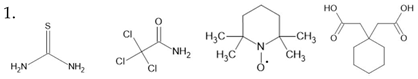 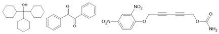 thiourea [129] TCAA [130] TEMPO [131] CDA [132] TCHM [133] Benzil [134] DNP [135] | ||
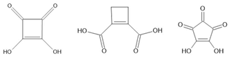 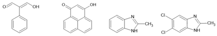 squaric acid [136] CBDC [137] croconic acid [138] PhMDA [137] 3-HPLN [137] MBI [139] DC-MBI [139] | ||
 1P [140] SF-PFA [141] |  |  guanine [142] glycine [143] thymine [144] FF [145] |
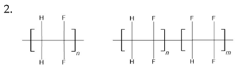 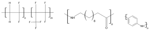 PVDF [146,147] P(VDF-TrFE) [148] P(VDF-HFP) [149] nylon 11 [150] 6,10,11,12-12 [151] PANI [152] | ||
 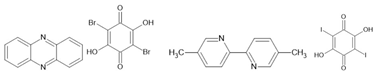 TTF/CA [153,154] TTF/BA [154] Phz/H2ca [155] Phz/H2ba [155] DMBP/H2ia [156] | ||
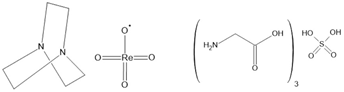 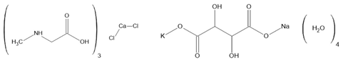 Hdabco/ReO4 [157] TGS [158,159] TSCC [160] Rochelle salt [161] | ||
Disclaimer/Publisher’s Note: The statements, opinions and data contained in all publications are solely those of the individual author(s) and contributor(s) and not of MDPI and/or the editor(s). MDPI and/or the editor(s) disclaim responsibility for any injury to people or property resulting from any ideas, methods, instructions or products referred to in the content. |
© 2024 by the author. Licensee MDPI, Basel, Switzerland. This article is an open access article distributed under the terms and conditions of the Creative Commons Attribution (CC BY) license (https://creativecommons.org/licenses/by/4.0/).
Share and Cite
MDPI and ACS Style
Borca, B. Advances in Organic Multiferroic Junctions. Coatings 2024, 14, 682. https://doi.org/10.3390/coatings14060682
AMA Style
Borca B. Advances in Organic Multiferroic Junctions. Coatings. 2024; 14(6):682. https://doi.org/10.3390/coatings14060682
Chicago/Turabian StyleBorca, Bogdana. 2024. "Advances in Organic Multiferroic Junctions" Coatings 14, no. 6: 682. https://doi.org/10.3390/coatings14060682
Note that from the first issue of 2016, this journal uses article numbers instead of page numbers. See further details here.