

Calcium Phosphate Coatings Deposited on 3D-Printed Ti–6Al–4V Alloy by Plasma Electrolytic Oxidation


Abstract
:1. Introduction
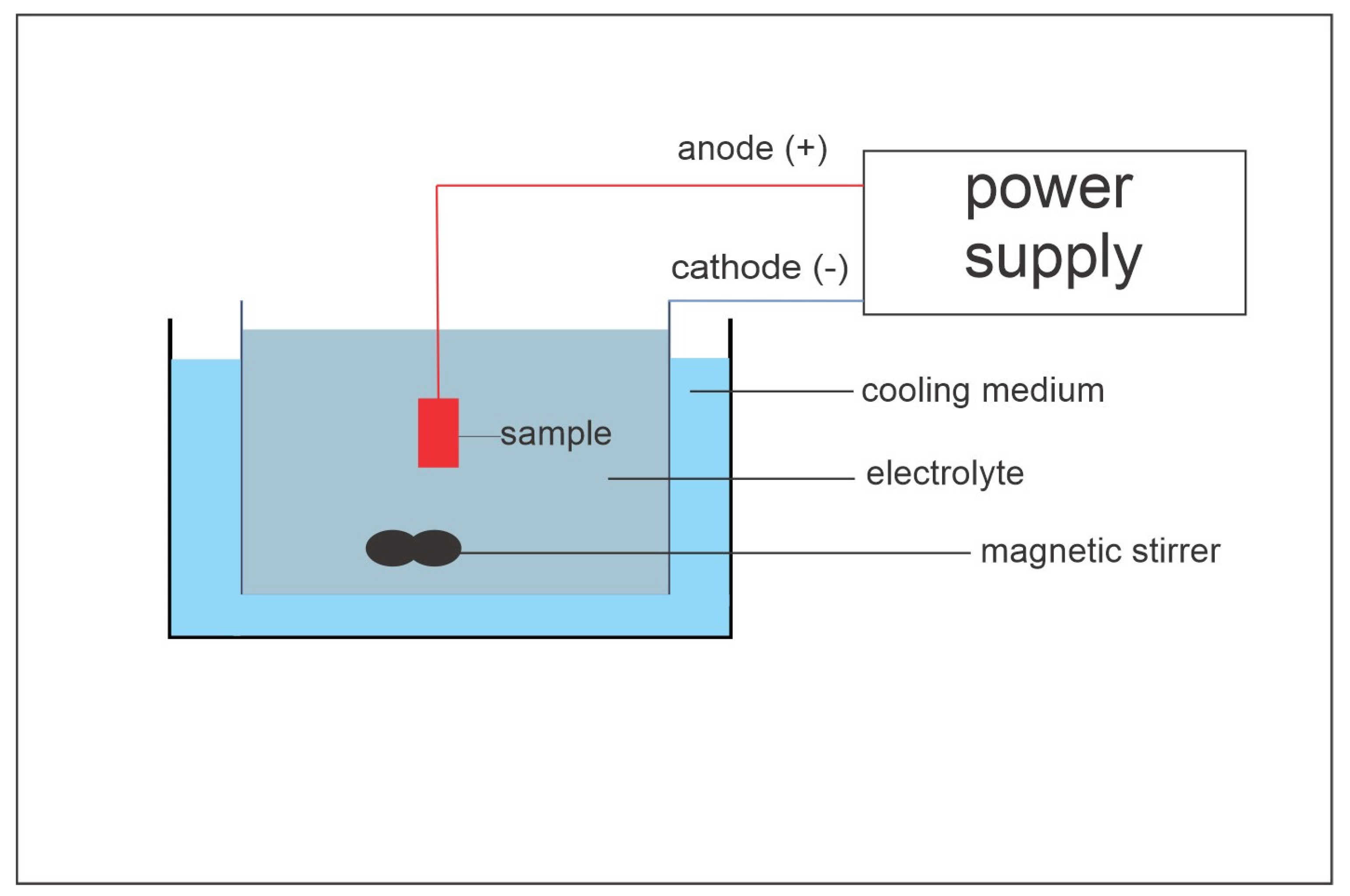
2. Materials and Methods
3. Results and Discussion
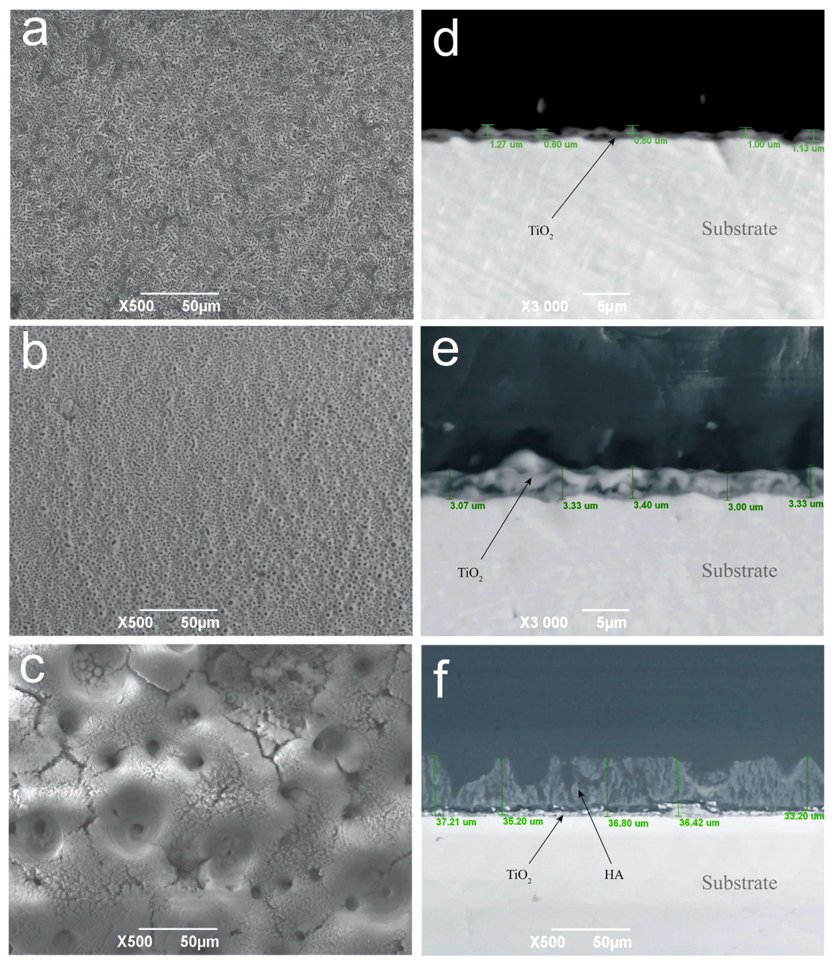
3.1. SEM–EDS Analysis of the Coatings
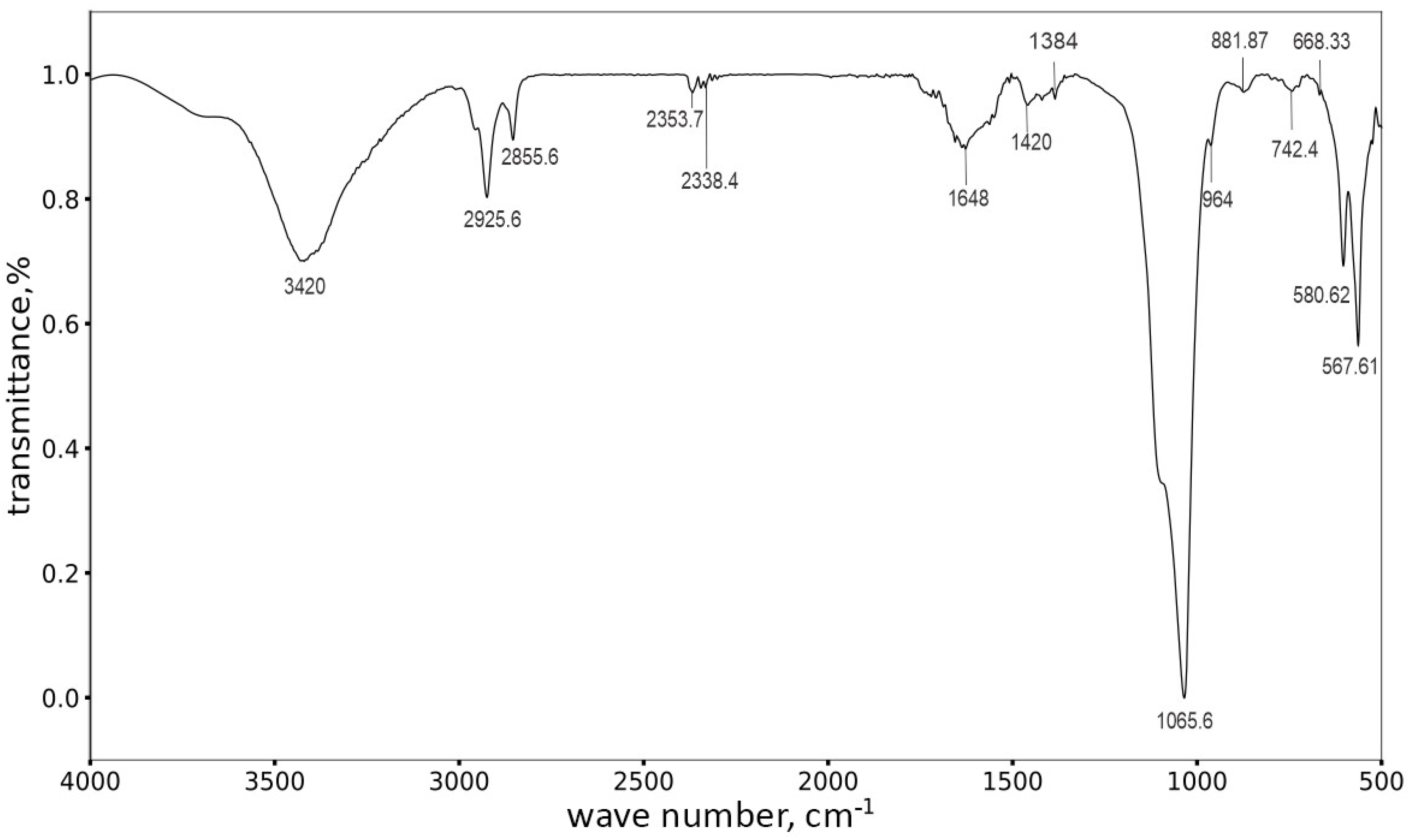
3.2. The X-ray Diffraction and FTIR Analysis of the Coatings
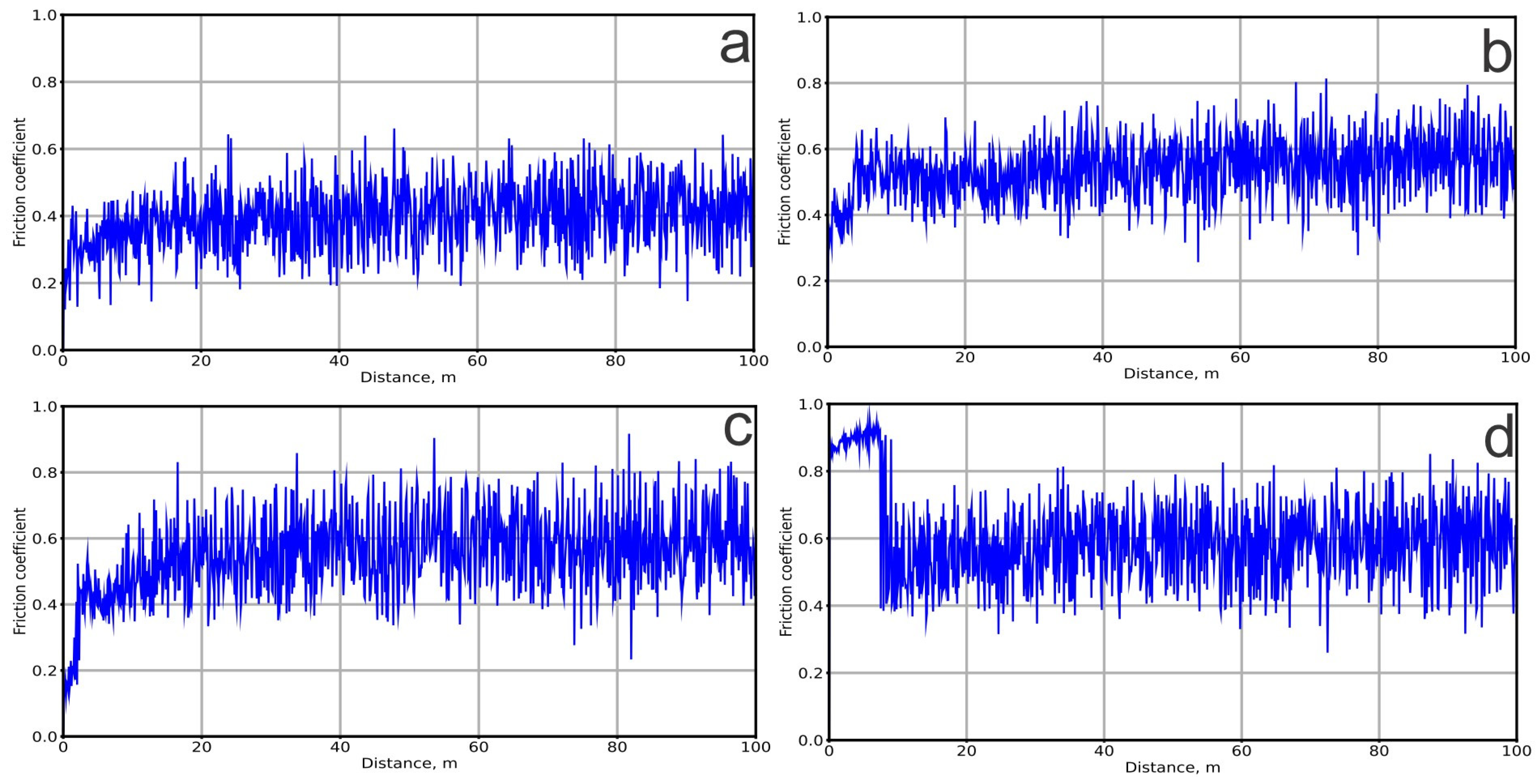
3.3. The Tribological and Mechanical Properties of the Coatings
4. Conclusions
Author Contributions
Funding
Institutional Review Board Statement
Informed Consent Statement
Data Availability Statement
Conflicts of Interest
References
- Lee, J.Y.; An, J.; Chua, C.K. Fundamentals and Applications of 3D Printing for Novel Materials. Appl. Mater. Today 2017, 7, 120–133. [Google Scholar] [CrossRef]
- Ngo, T.D.; Kashani, A.; Imbalzano, G.; Nguyen, K.T.Q.; Hui, D. Additive Manufacturing (3D Printing): A Review of Materials, Methods, Applications and Challenges. Compos. B Eng. 2018, 143, 172–196. [Google Scholar] [CrossRef]
- Myakinin, A.; Turlybekuly, A.; Pogrebnjak, A.; Mirek, A.; Bechelany, M.; Liubchak, I.; Oleshko, O.; Husak, Y.; Korniienko, V.; Leśniak-Ziółkowska, K.; et al. In Vitro Evaluation of Electrochemically Bioactivated Ti6Al4V 3D Porous Scaffolds. Mater. Sci. Eng. C 2021, 121, 111870. [Google Scholar] [CrossRef] [PubMed]
- Pesode, P.; Barve, S. Surface Modification of Titanium and Titanium Alloy by Plasma Electrolytic Oxidation Process for Biomedical Applications: A Review. Mater. Today Proc. 2021, 46, 594–602. [Google Scholar] [CrossRef]
- Ramakrishna, S.; Mayer, J.; Wintermantel, E.; Leong, K.W. Biomedical Applications of Polymer-Composite Materials: A Review. Compos. Sci. Technol. 2001, 61, 1189–1224. [Google Scholar] [CrossRef]
- Kaseem, M.; Choe, H.C. The Effect of In-Situ Reactive Incorporation of MoOx on the Corrosion Behavior of Ti-6Al-4 V Alloy Coated via Micro-Arc Oxidation Coating. Corros. Sci. 2021, 192, 109764. [Google Scholar] [CrossRef]
- Li, G.; Ma, F.; Liu, P.; Qi, S.; Li, W.; Zhang, K.; Chen, X. Review of Micro-Arc Oxidation of Titanium Alloys: Mechanism, Properties and Applications. J. Alloys Compd. 2023, 948, 169773. [Google Scholar] [CrossRef]
- Grebņevs, V.; Leśniak-Ziółkowska, K.; Wala, M.; Dulski, M.; Altundal, Ş.; Dutovs, A.; Avotiņa, L.; Erts, D.; Viter, R.; Vīksna, A.; et al. Modification of Physicochemical Properties and Bioactivity of Oxide Coatings Formed on Ti Substrates via Plasma Electrolytic Oxidation in Crystalline and Amorphous Calcium Phosphate Particle Suspensions. Appl. Surf. Sci. 2022, 598, 153793. [Google Scholar] [CrossRef]
- Sowa, M.; Piotrowska, M.; Widziołek, M.; Dercz, G.; Tylko, G.; Gorewoda, T.; Osyczka, A.M.; Simka, W. Bioactivity of Coatings Formed on Ti–13Nb–13Zr Alloy Using Plasma Electrolytic Oxidation. Mater. Sci. Eng. C 2015, 49, 159–173. [Google Scholar] [CrossRef]
- Mamaeva, A.; Kenzhegulov, A.; Kowalewski, P.; Wieleba, W. Investigation of Hydroxyapatite-Titanium Composite Properties during Heat Treatment. Acta Bioeng. Biomech. 2017, 19, 161–169. [Google Scholar] [CrossRef]
- Barrino, F. Hybrid Organic–Inorganic Materials Prepared by Sol–Gel and Sol–Gel-Coating Method for Biomedical Use: Study and Synthetic Review of Synthesis and Properties. Coatings 2024, 14, 425. [Google Scholar] [CrossRef]
- Kowalski, S.; Gonciarz, W.; Belka, R.; Góral, A.; Chmiela, M.; Lechowicz, Ł.; Kaca, W.; Żórawski, W. Plasma-Sprayed Hydroxyapatite Coatings and Their Biological Properties. Coatings 2022, 12, 1317. [Google Scholar] [CrossRef]
- Schwartz, A.; Kossenko, A.; Zinigrad, M.; Danchuk, V.; Sobolev, A. Cleaning Strategies of Synthesized Bioactive Coatings by PEO on Ti-6Al-4V Alloys of Organic Contaminations. Materials 2023, 16, 4624. [Google Scholar] [CrossRef]
- Jarosz, M.; Grudzień, J.; Kapusta-Kołodziej, J.; Chudecka, A.; Sołtys, M.; Sulka, G.D. Chapter Seven—Anodization of Titanium Alloys for Biomedical Applications. In Nanostructured Anodic Metal Oxides; Sulka, G.D., Ed.; Micro and Nano Technologies; Elsevier: Amsterdam, The Netherlands, 2020; pp. 211–275. ISBN 978-0-12-816706-9. [Google Scholar]
- Naji Chabuk, Q.K.; Salman Al-Murshdy, J.M.; Dawood, N.M. Review: The Surface Modification of Pure Titanium by Micro-Arc Oxidation (MAO) Process. J. Phys. Conf. Ser. 2021, 1973, 012114. [Google Scholar] [CrossRef]
- Santos-Coquillat, A.; Martínez-Campos, E.; Mohedano, M.; Martínez-Corriá, R.; Ramos, V.; Arrabal, R.; Matykina, E. In Vitro and in Vivo Evaluation of PEO-Modified Titanium for Bone Implant Applications. Surf. Coat. Technol. 2018, 347, 358–368. [Google Scholar] [CrossRef]
- Lin, D.J.; Fuh, L.J.; Chen, W.C. Nano-Morphology, Crystallinity and Surface Potential of Anatase on Micro-Arc Oxidized Titanium Affect Its Protein Adsorption, Cell Proliferation and Cell Differentiation. Mater. Sci. Eng. C 2020, 107, 110204. [Google Scholar] [CrossRef] [PubMed]
- Aliasghari, S.; Skeleton, P.; Thompson, G.E. Plasma Electrolytic Oxidation of Titanium in a Phosphate/Silicate Electrolyte and Tribological Performance of the Coatings. Appl. Surf. Sci. 2014, 316, 463–476. [Google Scholar] [CrossRef]
- Santos, P.B.; de Castro, V.V.; Baldin, E.K.; Aguzzoli, C.; Longhitano, G.A.; Jardini, A.L.; Lopes, É.S.N.; de Andrade, A.M.H.; de Fraga Malfatti, C. Wear Resistance of Plasma Electrolytic Oxidation Coatings on Ti-6Al-4V Eli Alloy Processed by Additive Manufacturing. Metals 2022, 12, 1070. [Google Scholar] [CrossRef]
- Kengesbekov, A.; Sagdoldina, Z.; Torebek, K.; Baizhan, D.; Kambarov, Y.; Yermolenko, M.; Abdulina, S.; Maulet, M. Synthesis and Formation Mechanism of Metal Oxide Compounds. Coatings 2022, 12, 1511. [Google Scholar] [CrossRef]
- Ji, R.; Wang, H.; Wang, B.; Jin, H.; Liu, Y.; Cheng, W.; Cai, B.; Li, X. Removing Loose Oxide Layer and Producing Dense α-Phase Layer Simultaneously to Improve Corrosion Resistance of Ti-6Al-4V Titanium Alloy by Coupling Electrical Pulse and Ultrasonic Treatment. Surf. Coat. Technol. 2020, 384, 125329. [Google Scholar] [CrossRef]
- Yu, J.M.; Kim, H.J.; Ahn, S.G.; Choe, H.C. Plasma Electrolytic Oxidation of Ti-6Al-4V Alloy in Electrolytes Containing Bone Formation Ions. Appl. Surf. Sci. 2020, 513, 145776. [Google Scholar] [CrossRef]
- Bocchetta, P.; Chen, L.Y.; Tardelli, J.D.C.; Dos Reis, A.C.; Almeraya-Calderón, F.; Leo, P. Passive Layers and Corrosion Resistance of Biomedical Ti-6al-4v and β-Ti Alloys. Coatings 2021, 11, 487. [Google Scholar] [CrossRef]
- Durdu, S.; Deniz, Ö.F.; Kutbay, I.; Usta, M. Characterization and Formation of Hydroxyapatite on Ti6Al4V Coated by Plasma Electrolytic Oxidation. J. Alloys Compd. 2013, 551, 422–429. [Google Scholar] [CrossRef]
- Mamaeva, A.; Kenzhegulov, A.; Panichkin, A.; Abdulvaliyev, R.; Kshibekova, B.; Arynbayev, T. Mechanical Grinding of Hydroxyapatite and Its Interaction with Titanium. Coatings 2024, 14, 333. [Google Scholar] [CrossRef]
- Sukhodub, L.F.; Pogrebnjak, A.D.; Sukhodub, L.B.; Sagidugumar, A.; Kistaubayeva, A.S.; Savitskaya, I.S.; Talipova, A.; Sadibekov, A.; Kantay, N.; Akatan, K.; et al. Antibacterial and Physical Characteristics of Silver-Loaded Hydroxyapatite/Alginate Composites. Funct. Compos. Struct. 2021, 3, 045010. [Google Scholar] [CrossRef]
- Yu, J.M.; Choe, H.C. Morphology Changes and Bone Formation on PEO-Treated Ti-6Al-4V Alloy in Electrolyte Containing Ca, P, Sr, and Si Ions. Appl. Surf. Sci. 2019, 477, 121–130. [Google Scholar] [CrossRef]
- Yigit, O.; Dikici, B.; Ozdemir, N.; Arslan, E. Plasma Electrolytic Oxidation of Ti-6Al-4V Alloys in NHA/GNS Containing Electrolytes for Biomedical Applications: The Combined Effect of the Deposition Frequency and GNS Weight Percentage. Surf. Coat. Technol. 2021, 415, 127139. [Google Scholar] [CrossRef]
- Chen, W.M.; Xie, Y.; Imbalzano, G.; Shen, J.; Xu, S.; Lee, S.-J.; Lee, P. Lattice Ti Structures with Low Rigidity but Compatible Mechanical Strength: Design of Implant Materials for Trabecular Bone. Int. J. Precis. Eng. Manuf. 2016, 17, 793–799. [Google Scholar] [CrossRef]
- Dobrzanski, L.; Dobrzańska-Danikiewicz, A.D.; Malara, P.; Gaweł, T.; Dobrzański, L.B.; Achtelik-Franczak, A. Fabrication of Scaffolds from Ti6Al4V Powders Using the Computer Aided Laser Method. Arch. Metall. Mater. 2015, 60, 1065–1070. [Google Scholar] [CrossRef]
- Pei, X.; Zhang, B.; Fan, Y.; Zhu, X.; Sun, Y.; Wang, Q.; Zhang, X.; Zhou, C. Bionic Mechanical Design of Titanium Bone Tissue Implants and 3D Printing Manufacture. Mater. Lett. 2017, 208, 133–137. [Google Scholar] [CrossRef]
- Zadpoor, A.A. Mechanical Performance of Additively Manufactured Meta-Biomaterials. Acta Biomater. 2019, 85, 41–59. [Google Scholar] [CrossRef] [PubMed]
- Yang, C.; Cui, S.; Fu, R.K.Y.; Sheng, L.; Wen, M.; Xu, D.; Zhao, Y.; Zheng, Y.; Chu, P.K.; Wu, Z. Optimization of the in Vitro Biodegradability, Cytocompatibility, and Wear Resistance of the AZ31B Alloy by Micro-Arc Oxidation Coatings Doped with Zinc Phosphate. J. Mater. Sci. Technol. 2024, 179, 224–239. [Google Scholar] [CrossRef]
- Yu, J.-M.; Cho, H.-R.; Choe, H.-C. Electrochemical Characteristics of Sr/Si-Doped Hydroxyapatite Coating on the Ti Alloy Surface via Plasma Electrolytic Oxidation. Thin Solid. Films 2022, 746, 139124. [Google Scholar] [CrossRef]
- Park, M.-G.; Choe, H.-C. Corrosion Behaviors of Bioactive Element Coatings on PEO-Treated Ti-6Al-4V Alloys. Surf. Coat. Technol. 2019, 376, 44–51. [Google Scholar] [CrossRef]
- Yang, C.; Wang, C.; Zhao, X.; Shen, Z.; Wen, M.; Zhao, C.; Sheng, L.; Wang, Y.; Xu, D.; Zheng, Y.; et al. Superhydrophobic Surface on MAO-Processed AZ31B Alloy with Zinc Phosphate Nanoflower Arrays for Excellent Corrosion Resistance in Salt and Acidic Environments. Mater. Des. 2024, 239, 112769. [Google Scholar] [CrossRef]
- Yan, X.; Chen, C.; Bolot, R.; Ma, W.; Deng, C.; Wang, J.; Ren, Z.; Liao, H.; Liu, M. Improvement of Tribological Performance by Micro-Arc Oxidation Treatment on Selective Laser Melting Ti6Al4V Alloy. Mater. Res. Express 2019, 6, 096509. [Google Scholar] [CrossRef]
- Wu, G.; Wang, Y.; Sun, M.; Zhang, Q.; Yao, J. Influence of Microstructure of TC4 Substrate on the MAO Coating. Surf. Eng. 2020, 36, 827–836. [Google Scholar] [CrossRef]
- ISO 22674; Dentistry—Metallic Materials for Fixed and Removable Restorations and Appliances. International Organization for Standardization: Geneva, Switzerland, 2022.
- Sun, J.; Han, Y.; Huang, X. Hydroxyapatite Coatings Prepared by Micro-Arc Oxidation in Ca- and P-Containing Electrolyte. Surf. Coat. Technol. 2007, 201, 5655–5658. [Google Scholar] [CrossRef]
- Song, W.-H.; Jun, Y.-K.; Han, Y.; Hong, S.-H. Biomimetic Apatite Coatings on Micro-Arc Oxidized Titania. Biomaterials 2004, 25, 3341–3349. [Google Scholar] [CrossRef]
- Chocholata, P.; Kulda, V.; Dvorakova, J.; Supova, M.; Zaloudkova, M.; Babuska, V. In Situ Hydroxyapatite Synthesis Enhances Biocompatibility of Pva/Ha Hydrogels. Int. J. Mol. Sci. 2021, 22, 9335. [Google Scholar] [CrossRef]
- Klimova-Korsmik, O.G.; Turichin, G.A.; Shalnova, S.A.; Gushchina, M.O.; Cheverikin, V.V. Structure and Properties of Ti-6Al-4V Titanium Alloy Products Obtained by Direct Laser Deposition and Subsequent Heat Treatment. J. Phys. Conf. Ser. 2018, 1109, 012061. [Google Scholar] [CrossRef]
- He, Z.; Zeng, J.; Li, D.; Mei, L.; Luo, L.; He, H.; Li, Y. Controlling Elastic Modulus and Ultrasonic Property of Ti6Al4V Alloy for Ultrasonic Scalpel. Mater. Today Commun. 2022, 33, 104212. [Google Scholar] [CrossRef]
- Chen, H.T.; Chung, C.J.; Yang, T.C.; Tang, C.H.; He, J.L. Microscopic Observations of Osteoblast Growth on Micro-Arc Oxidized β Titanium. Appl. Surf. Sci. 2013, 266, 73–80. [Google Scholar] [CrossRef]
- Qian, J.; Yin, X.; Wang, N.; Liu, L.; Xing, J. Preparation and Tribological Properties of Stearic Acid-Modified Hierarchical Anatase TiO2 Microcrystals. Appl. Surf. Sci. 2012, 258, 2778–2782. [Google Scholar] [CrossRef]
- Yu, T.; Ye, J.; Gao, C.; Yu, L.; Wang, Y. Synthesis and Drug Delivery Property of Calcium Phosphate Cement with Special Crystal Morphology. J. Am. Ceram. Soc. 2010, 93, 1241–1244. [Google Scholar] [CrossRef]
- Vinoth Kumar, K.C.; Jani Subha, T.; Ahila, K.G.; Ravindran, B.; Chang, S.W.; Mahmoud, A.H.; Mohammed, O.B.; Rathi, M.A. Spectral Characterization of Hydroxyapatite Extracted from Black Sumatra and Fighting Cock Bone Samples: A Comparative Analysis. Saudi J. Biol. Sci. 2021, 28, 840–846. [Google Scholar] [CrossRef] [PubMed]
- Chen, Y.; Cheng, T.; Nie, X. Wear Failure Behaviour of Titanium-Based Oxide Coatings on a Titanium Alloy under Impact and Sliding Forces. J. Alloys Compd. 2013, 578, 336–344. [Google Scholar] [CrossRef]
- ASTM G99-17; Standard Test Method for Wear Testing with a Pin-on-Disk Apparatus. ASTM International: West Conshohocken, PA, USA, 2023. Available online: https://www.astm.org/g0099-17.html (accessed on 20 May 2024).
- Pogrebnjak, A.D.; Lisovenko, M.A.; Turlybekuly, A.; Buranich, V. V Protective Coatings with Nanoscale Multilayer Architecture: Current State and Main Trends. Physics-Uspekhi 2021, 64, 253. [Google Scholar] [CrossRef]
- Mashtalyar, D.V.; Nadaraia, K.V.; Gnedenkov, A.S.; Imshinetskiy, I.M.; Piatkova, M.A.; Pleshkova, A.I.; Belov, E.A.; Filonina, V.S.; Suchkov, S.N.; Sinebryukhov, S.L.; et al. Bioactive Coatings Formed on Titanium by Plasma Electrolytic Oxidation: Composition and Properties. Materials 2020, 13, 4121. [Google Scholar] [CrossRef]


 α Ti (ICSD 98-007-6265),
  β Ti (ICSD 98-004-1503),
  HA (ICSD 98-005-6309),
  Anatase (ICSD 98-008-2084), and
  Rutile (ICSD 98-003-3844)).
α Ti (ICSD 98-007-6265), β Ti (ICSD 98-004-1503), HA (ICSD 98-005-6309), Anatase (ICSD 98-008-2084), and Rutile (ICSD 98-003-3844)).
Rutile (ICSD 98-003-3844)).
α Ti (ICSD 98-007-6265), β Ti (ICSD 98-004-1503), HA (ICSD 98-005-6309), Anatase (ICSD 98-008-2084), and Rutile (ICSD 98-003-3844)).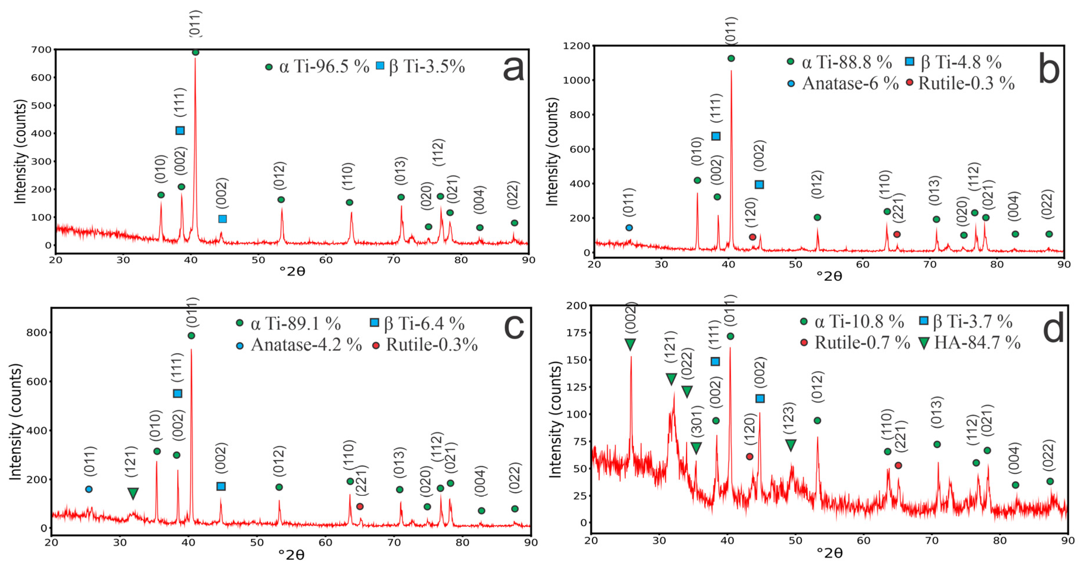


| Pulse Voltage | Current Density | Duty Cycle | Pulse Frequency | Processing Time |
|---|---|---|---|---|
| 200 V | 0.057 A/cm2 | 10% | 50 Hz | 5 min |
| 250 V | 0.11 A/cm2 | 10% | 50 Hz | 5 min |
| 300 V | 0.2 A/cm2 | 10% | 50 Hz | 5 min |
| Element (wt.%) | 200 V | 250 V | 300 V |
|---|---|---|---|
| O | 44.15 ± 3.31 | 41.88 ± 5.72 | 39.63 ± 9.15 |
| P | 1.81 ± 0.19 | 2.15 ± 0.27 | 20.03 ± 2.00 |
| Ca | 4.06 ± 0.69 | 6.44 ± 0.92 | 39.34 ± 7.30 |
| Ti | 45.24 ± 3.16 | 45.36 ± 5.22 | 1.01 ± 0.13 |
| Al | 2.75 ± 0.11 | 2.24 ± 0.18 | - |
| V | 1.99 ± 0.24 | 1.93 ± 0.33 | - |
| Ca/P | 2.24 | 2.99 | 1.96 |
| Sample | Coefficient of Friction | Wear Rate (mm³/N/m) |
|---|---|---|
| Control sample (Ti–6Al–4V) | 0.396 | 3.087 × 10⁻⁴ |
| 200 V | 0.540 | 3.447 × 10⁻⁴ |
| 250 V | 0.546 | 2.765 × 10⁻⁴ |
| 300 V | 0.600 | 3.270 × 10⁻⁴ |
Disclaimer/Publisher’s Note: The statements, opinions and data contained in all publications are solely those of the individual author(s) and contributor(s) and not of MDPI and/or the editor(s). MDPI and/or the editor(s) disclaim responsibility for any injury to people or property resulting from any ideas, methods, instructions or products referred to in the content. |
© 2024 by the authors. Licensee MDPI, Basel, Switzerland. This article is an open access article distributed under the terms and conditions of the Creative Commons Attribution (CC BY) license (https://creativecommons.org/licenses/by/4.0/).
Share and Cite
Sagidugumar, A.; Dogadkin, D.; Turlybekuly, A.; Kaliyev, D. Calcium Phosphate Coatings Deposited on 3D-Printed Ti–6Al–4V Alloy by Plasma Electrolytic Oxidation. Coatings 2024, 14, 696. https://doi.org/10.3390/coatings14060696
Sagidugumar A, Dogadkin D, Turlybekuly A, Kaliyev D. Calcium Phosphate Coatings Deposited on 3D-Printed Ti–6Al–4V Alloy by Plasma Electrolytic Oxidation. Coatings. 2024; 14(6):696. https://doi.org/10.3390/coatings14060696
Chicago/Turabian StyleSagidugumar, Amangeldi, Dmitriy Dogadkin, Amanzhol Turlybekuly, and Daniyar Kaliyev. 2024. "Calcium Phosphate Coatings Deposited on 3D-Printed Ti–6Al–4V Alloy by Plasma Electrolytic Oxidation" Coatings 14, no. 6: 696. https://doi.org/10.3390/coatings14060696