Article

Research on Key Technologies of Jewelry Design and Manufacturing Based on 3D Printing Technology

School of Mechanical and Electrical Engineering, Zhoukou Normal University, Zhoukou 466000, China
*
Author to whom correspondence should be addressed.
Coatings 2024, 14(6), 701; https://doi.org/10.3390/coatings14060701
Submission received: 11 May 2024 / Revised: 22 May 2024 / Accepted: 30 May 2024 / Published: 3 June 2024
(This article belongs to the Special Issue Recent Advances in Additive Manufacturing Techniques)

Abstract

:
In conjunction with the swift enhancement of China’s economic prowess, the demand for jewelry among the populace is gradually evolving towards personalized, customized, and intricate designs. Traditional manufacturing approaches are increasingly inadequate to meet these evolving demands. However, the advent of 3D printing technology presents a viable solution for the direct fabrication of such sophisticated jewelry. To this end, the conceptualization of personalized jewelry inspiration is initiated, followed by the implementation of parametric design using SolidWorks 2018 software. Subsequently, 3D printing technology is employed to materialize the jewelry directly. Results indicate that the “Guardian” jewelry model, crafted through the parametric modeling method, exhibits a commendable design, and adheres to processing requirements following a comprehensive risk analysis. The strategic adjustment of the jewelry’s position effectively reduces the required support, circumventing the necessity of adding support to critical surfaces. The surface of the Selective Laser Melting (SLM)-manufactured “Guardian” jewelry boasts a lustrous finish, showcasing optimal overlap between pillars and excellent connectivity among pores. Minimal powder adherence on the surface is observed, enabling direct utilization post-sandblasting, polishing, and plating. This establishes a solid foundation for the direct application of SLM-manufactured personalized jewelry.

1. Introduction

With the continual enhancement of living standards, the expectations for jewelry have concurrently risen. In contemporary society, jewelry transcends its conventional role as a mere embellishment for personal appearance; instead, it is increasingly perceived as an expression of individual taste and depth. The materials utilized in jewelry production have also undergone diversification. Beyond the conventional requisites of comfort and aesthetics, design preferences are inclining towards personalization, customization, and structural intricacy. Consequently, there is an imperative demand for innovative design and development in the realm of jewelry. Traditional jewelry production techniques such as Chasing Craftsmanship, Filigree Craftsmanship, Blue Patina Craftsmanship, Inlay Craftsmanship, etc., have become inadequate in meeting the current processing requirements of contemporary jewelry design.
Additive manufacturing technology, commonly known as 3D printing, utilizes specialized data processing software to slice and layer three-dimensional models, generating cross-sectional data. This data is then imported into 3D printing equipment, employing a layer-by-layer approach to manufacture solid parts. The layer-by-layer method enables 3D printing technology to produce parts of almost any geometric shape, offering advantages such as processing single pieces, handling small batches, accommodating complex geometric structures, and achieving dense organization. This capability establishes the feasibility of directly manufacturing personalized, customized, and intricate jewelry [1,2]. The adoption of 3D technology allows enterprises to significantly reduce the production cycle and production costs of jewelry, making it particularly meaningful in the context of our country’s development. Selective Laser Melting (SLM) technology, a form of 3D printing, relies on laser melting of metal powder [3,4,5,6].
Ji Fangshu et al. [7] conducted an investigation on the application of 3D printing technology in jewelry design and the disparities between traditional jewelry production and 3D printing methods. Their analysis focused on the impact of 3D printing on enhancing specific aspects of traditional jewelry production and explored innovative technological approaches in jewelry manufacturing. This research contributes significantly to the advancement of jewelry design and production. Zhang Wenwen et al. [8] proposed the utilization of 3D printing technology to create jewelry boxes with novel and diverse shapes, aiming to reduce dependence on traditional manufacturing processes. This approach enables the swift transformation of creative designs into tangible products, breaking away from conventional industry norms. By applying this technology to customized product designs tailored to users’ needs and preferences, individuals can directly experience the pleasure derived from personalized design. Yang Jingzhou et al. [9] employed Rhinoceros software to model a lotus root shape and utilized the lightweight function of 3-Matic STL to process the STL model. Adhering to the fish basket design concept, they undertook structural reorganization, adjusting the diameter and spacing of the model structure through printing experiments. This resulted in reduced weight without compromising model quality and printing success rates. Luo Jingjing et al. [10] integrated 3D printing technology into traditional woven jewelry, introducing various changes to the linear shape of woven materials. This innovative approach redefines the design concept of woven jewelry, breaking free from traditional linear material constraints and producing more novel and ornamental works. This not only infuses new vitality into traditional woven jewelry but also caters to people’s desire for innovative jewelry. Xiong Wei et al. [11] introduced the design concept and principles of a jewelry movable structure based on Selective Laser Melting (SLM) technology. Their study focused on metal flexible structures, shutter movable structures, bearing movable structures, and spindle movable structures in jewelry processing.
Jewelry design and manufacturing using 3D printing technology have emerged as crucial developmental directions. However, there remains a need to investigate the design efficacy, model quality, and success rates of jewelry produced through 3D printing. This paper thus concentrates on exploring the design methodologies and molding processes employed in the creation of personalized, customized jewelry.

2. Design Constraints, Materials, and Methods

2.1. Design Constraints

The application of 3D printing technology for part manufacturing provides a greater degree of freedom compared to traditional manufacturing methods. However, it is essential to recognize that this does not imply the capability to produce parts with arbitrary geometries. Design constraints are critical, and a failure to align with these constraints may result in processing failures. By considering the constraints imposed by manufacturing conditions during the jewelry design phase and strategically avoiding limitations associated with processing technology, a balance can be achieved between design freedom and the constraints of molding. This alignment ensures a harmonious fit, contributing to the quality assurance of jewelry molding and mitigating the risk of molding failures.
(1) The 45-Degree Angle Constraint
Metal 3D printer-molded parts should avoid overhanging more than 45 degrees, as exceeding this angle can lead to the collapse of the molded part. Therefore, it is advisable to steer clear of larger angles of protrusion in the design of our jewelry.
(2) Optimizing Design with Minimal Support
When 3D printers mold parts with added support, the support and the parts are molded together. The removal of the support can result in unsightly traces on top of the parts, and the process of eliminating these traces is time-consuming and labor-intensive. Therefore, different types of support tailored to the model’s characteristics should be added, and the support structure should be optimized to avoid excessive support.
(3) Sharp Corner–Thin Wall Constraint
Due to the minimum spot constraint for laser focusing, the thickness or width of thin walls with sharp corners in jewelry design should be larger than the laser spot diameter.
(4) Reasonable Tolerance Settings
Parts molded by 3D printers inherently possess a certain degree of error, especially in moving parts, internal holes, and the like. When designing models with high precision requirements, tolerances must be reasonably set. For instance, compensation should be provided for internal holes.

2.2. Material and Methods

Based on the mechanical properties of 316L stainless steel, the selected material for jewelry formation in this study is 316L stainless steel powder from SANDVIK Osprey company in the UK. The composition of the powder complies with the requirements of ASTM A276, and its compositional comparison is presented in Table 1. The particle size distribution of 316L stainless steel powder exhibits a narrow zone of concentrated distribution, with 90% of particles at −22 μm and a D50 value of −28.5 μm. Te powder was prepared by gas atomization and was spherical, as shown in Figure 1.
GYD 150 molding equipment produced by Shenzhen Sunshine Laser & Electronics Technology Co., Ltd. (Shenzhen, China) was used as the molding equipment. N2 was utilized as the protective gas, and the oxygen content was maintained below 0.03%. Processing parameters included a laser power of 170 W, scanning speed of 500 mm/s, scanning pitch of 60 μm, and processing layer thickness of 35 μm. The X-Y interlayer interlaced scanning strategy was employed. The completed jewelry in the processing design comprised no fewer than 3 units.

3. Results and Discussion
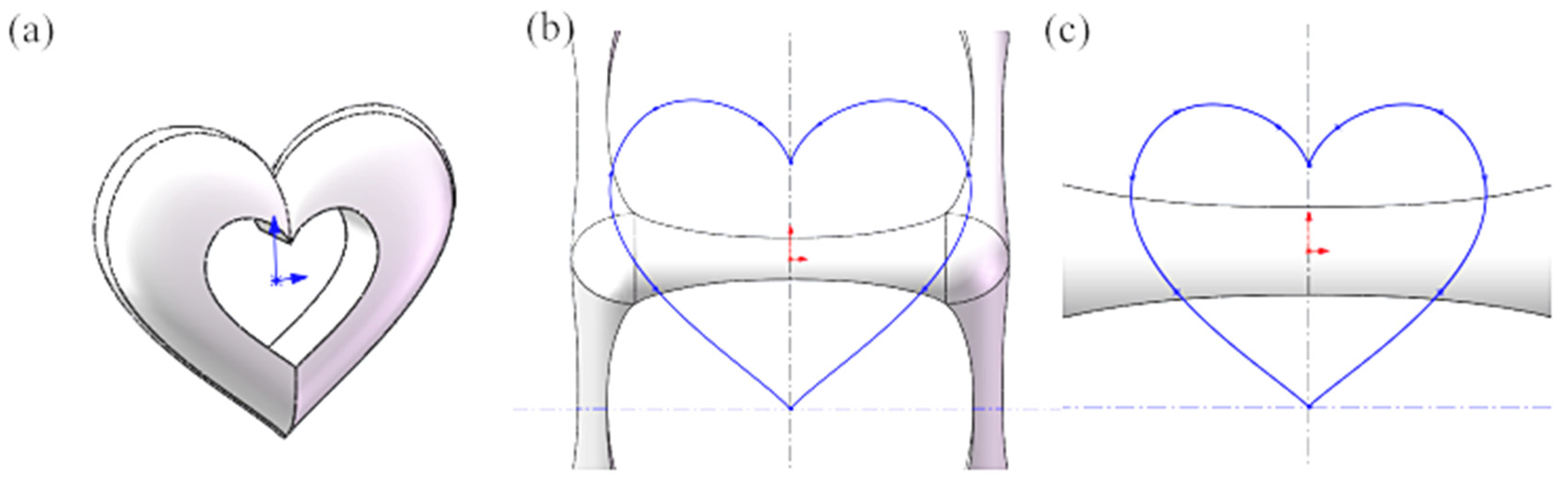
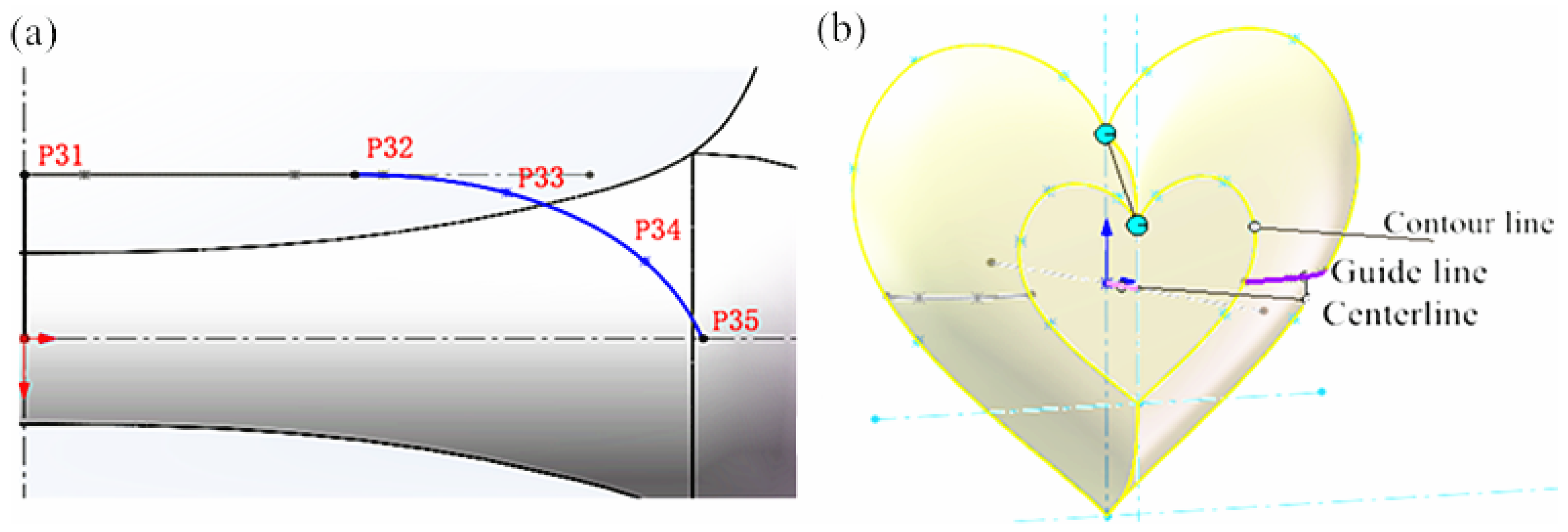
3.1. Design Concept

Jia et al. [12] analyzed the basic situation of mortise and tenon structures and 3D printing technology, explored the design application of mortise and tenon structures in 3D-printed jewelry, and finally obtained innovative design solutions for replaceable mortise and tenon jewelry through 3D printing technology. When designing this necklace, the concept of “Guardian” emerged as a profound and meaningful inspiration. The connotation of this term is inherently significant, representing a noble and honorable responsibility that extends to various aspects of our lives. Each one of us assumes the role of a guardian, whether it be safeguarding our nation, protecting our family, friends, and loved ones, or cherishing the memories of those who have lost someone dear. The design of the 3D-printed jewelry revolves around the theme of “Guardian”, drawing inspiration from the various forms of guardianship in our lives. Contemplating the term “Guardian”, the imagery that surfaces prominently is that of parents opening their arms to envelop us in an embrace. The notion of guardianship also evokes memories of a teacher who shielded a student in their arms in the face of the Wenchuan earthquake, prioritizing the student’s safety over their own. To be a guardian means ensuring the well-being of everything we hold dear, even at the risk of our safety. In expressing the significance of guardianship through jewelry, the design incorporates a metaphorical concept of “layers of wrapping”. This symbolizes the layers enveloping our hearts, signifying a perpetual commitment to “always guarding and never forgetting the original essence”. The essence conveyed is one of eternal vigilance and a steadfast commitment to the fundamental principles that guide us.

3.2. Design of 3D-Printed Jewelry

The paper focuses on utilizing SolidWorks 2018 3D drawing software for the conceptualization of jewelry shapes.
Prior to generating a 3D drawing for the intended jewelry design, it is crucial to determine the initial steps and meticulously calculate various parameters. These parameters include the dimensions of the jewelry, the lengths of contour curves, and other relevant details. The jewelry design is segmented into four parts, with a central heart-shaped model surrounded by three square skeletons. The procedural steps are outlined as follows:
After analyzing the characteristics of the skeleton framework, it was decided to draw the skeleton architecture model using the outside-in design method. Firstly, SolidWorks is employed to create a square cube with the origin as the center point. Subsequently, the outermost skeleton structure of the square is drawn with a side length of L1 = 14.00 mm, followed by the middle skeleton structure with a side length of L2 = 12.50 mm. Finally, the innermost layer of the square is drawn with a side length of L3 = 11.00 mm. Note: The design of the innermost layer of the square differs from that of the outermost and middle layers. As shown in Figure 2.
Rounding is applied to each edge of the drawn square to determine the wall thickness of the three layers of skeleton architecture and the curvature of the curve of the hollow contour. This ensures that the radius of the rounded corners for the three layers of skeleton architecture is designed to be equal, aligning with the visual aesthetics of the necklace. The rounded corners for the outermost, middle, and inner layers are R1 = R2 = R3 = 1.60 mm. The lengths of the square planes within the rounded corners are calculated as follows: L1 = (14.00 − 1.60) = 12.40 mm, L2 = (12.50 − 1.60) = 10.90 mm, and L3 = (11.00 − 1.60) mm = 9.40 mm.
Subsequently, the chamfered square is hollowed out using a subtractive shell process. Prior to the hollowing process, the wall thickness of the architecture (δ) is considered, as the rounded corners of the architecture are designed in conjunction with the wall thickness of the necklace as a design parameter. Therefore, each layer maintains an equal radius of rounded corners (R), and their wall thicknesses (δ) are uniform to achieve the aesthetic appeal of the necklace. The wall thicknesses for the outermost, middle, and innermost layers are denoted as δ1 = δ2 = δ3 = 0.50 mm, respectively.
The hollowed-out square undergoes a curvilinear resection on each face by applying a tensile resection to the hollowed structure. Due to the curvilinear resection, precise dimensions are essential, and the appearance of each layer of the hollowed architecture is modeled, as depicted in Figure 3a. The specific dimensions of the outermost layer are illustrated in Figure 3b. The coordinates of the points along the spline curve to the right from the position of the vertex above it are P1 = (0, 6.10), P2 = (4, 5.85), P3 = (5.40, 5.40), P4 = (5.85, 4.00), and P5 = (6.10, 0). The remaining points are symmetrical to the points P1, P2, P3, P4, and P5 on the x- and y-axes, respectively. The detailed dimensions of the middle layer are presented in Figure 3c. The coordinates of the points along the spline curve to the right from the position of the vertex above it are P6 = (0, 5.45), P7 = (3.20, 5.20), P8 = (4.65, 4.65), P9 = (5.20, 3.20), and P10 = (5.45, 0). The remaining points are symmetrical to P6, P7, P8, P9, and P10 on the x- and y-axes, respectively.
The detailed dimensions of the stretched excised spline curve for the innermost layer, when viewed from the right, with x and y as the positive directions of the coordinate axes, reveal coordinates of the points along the spline curve: P11 = (0, 4.60), P12 = (3.20, 4.25), P13 = (3.90, 3.90), P14 = (4.25, 3.20), and P15 = (4.60, 0). Furthermore, the dimensions of the spline curve for the stretching resection of the two adjacent faces of the innermost layer, when observed from the left with coordinates along the spline curve to the left from the position of the vertices above them, are sequentially noted as P16 = (0, 4.60), P17 = (−3.20, 4.25), P18 = (−3.90, 3.90), P19 = (−4.25, 3.20), P20 = (−4.60, 0).
The final part involves the design of the central “heart” structure, as depicted in Figure 4a. The contour lines of the heart must adhere to the Cartesian heart formula.
F ( x ) = tan ( 1 | x | 3 2 ) + π 2
G ( x ) = 1 4 ( x + 1 2 ) 2 + π 2
H ( x ) = 1 4 ( x 1 2 ) 2 + π 2
The dimensional data for the outer contour of the “heart” model is illustrated in Figure 4b. Following the Cartesian heart formula, the coordinates of each point on the spline are determined with the lower apex of the heart as the coordinate origin. The coordinates of the points to the right along the heart’s contour line from the origin are as follows: P21 = (3.38, 3.00), P22 = (4.50, 5.85), P23 = (3.38, 7.50), P24 = (0.75, 7.13), and P25 = (0, 6.15). The dimensional data for the inner contour line is presented in Figure 4c. Again, adhering to the Cartesian formula, the subsequent vertex is considered as the coordinate origin to position each coordinate point on the heart-shaped contour line. Starting from the origin coordinates along the heart-shaped contour line to the right, the point coordinates are in the following order: P26 = (1.58, 1.37), P27 = (2.10, 2.73), P28 = (1.58, 3.50), P29 = (0.35, 3.33), and P30 = (0, 2.87).
Next, guide lines for the heart-shaped surface are drawn, using the origin as the coordinate point. The coordinates for each spline curve point are as follows: P31 = (0, 1.00), P32 = (1.92, 1.00), P33 = (2.81, 0.89), P34 = (3.62, 0.47), and P35 = (3.96, 0). The coordinates on the left side are symmetric to P31, P32, P33, P34, and P35 across the center axis. It is important to note that P32 must coincide with and penetrate the inner contour line of the heart, while P35 must coincide with and penetrate the outer contour line of the heart, as depicted in Figure 5a.
Once all the heart contour lines and guide lines are drawn, proceed by clicking Insert → Buttress/Substrate → Release. Select both the outer and inner contours of the drawn heart in the sketch contour. In the guide line, choose the release curve on the outline guide line and select the straight line between the center line and the origin at point P31. Upon completing the selection, click Finish to generate a half-surface model of the heart, as illustrated in Figure 5b.
After that, go to Insert → Array/Mirror → Mirror, and choose the front view datum in Mirror/Datum. For Mirror Entity, select the released body you just sketched. Note: Ensure the “Merge Entities” option is checked in the options.
Switch to the top view datum by clicking Sketch to enter the sketch section. Draw a circle with the origin as the center and a radius of R = 0.40 mm. Next, click Insert → Buttress/Substrate → Stretch, using the circle as the cross-section contour to create a cylinder that connects with the innermost frame. Choose “Form to Solid” for the Given Depth option in Direction 1. Then, select the innermost frame in Solid/Surface Solid, as illustrated in Figure 6a. Check the box in front of Direction 2, similar to Direction 1. Opt for “Form to Solid” for the Given Depth option and choose the innermost frame in Solid/Surface Solids, as shown in Figure 6b. Note: In Direction 1, make sure to check the box in front of “Merge Results”.
Choose the inner heart and click “Edit Sketch” on this plane to enter the sketch. Select the inner curve and click “Convert Entity References” to convert the first heart to the current sketch. Click Insert → Cut → Stretch, and the center of the heart will be hollowed out. Finally, round the outer contour of the heart.
Click Sketch on the right view datum, draw a circle with a diameter of 0.50 mm and a distance from the center point to the center point of the sketch of S1 = 7.20 mm. In the straight-line sketch, choose the center line from the drop-down options. Draw a horizontal line above the center point with a distance from the center of the sketch of S2 = 7.60 mm. Then, click Insert → Bump/Base → Rotate. Choose the center of the line as the rotation axis and leave the Direction 1 option as the default. Note: “Merge Result” in Direction 1 must be selected. The completed model of the innermost frame is displayed in Figure 7a.
Assemble the three hollow architectures. Click on “Insert Part” in the assembly and select the innermost architecture, followed by the middle architecture and the outermost architecture. Ensure that the centers of the three architectures coincide. Sequentially align the centers of the three-tier architecture with the center of the assembly. Use the fit function in the assembly. In the fit selection of the entities to be fitted, constrain the centers of the three layers of the architecture to the centers of the adapter, checking the “Overlap” option in the standard fit. Note: Ensure the checkboxes in front of the alignment axes remain unchecked.
The 3D model of the “Guardian” jewelry designed using SolidWorks is depicted in Figure 7b.

3.3. Analysis of the Machinability of 3D-Printed Jewelry

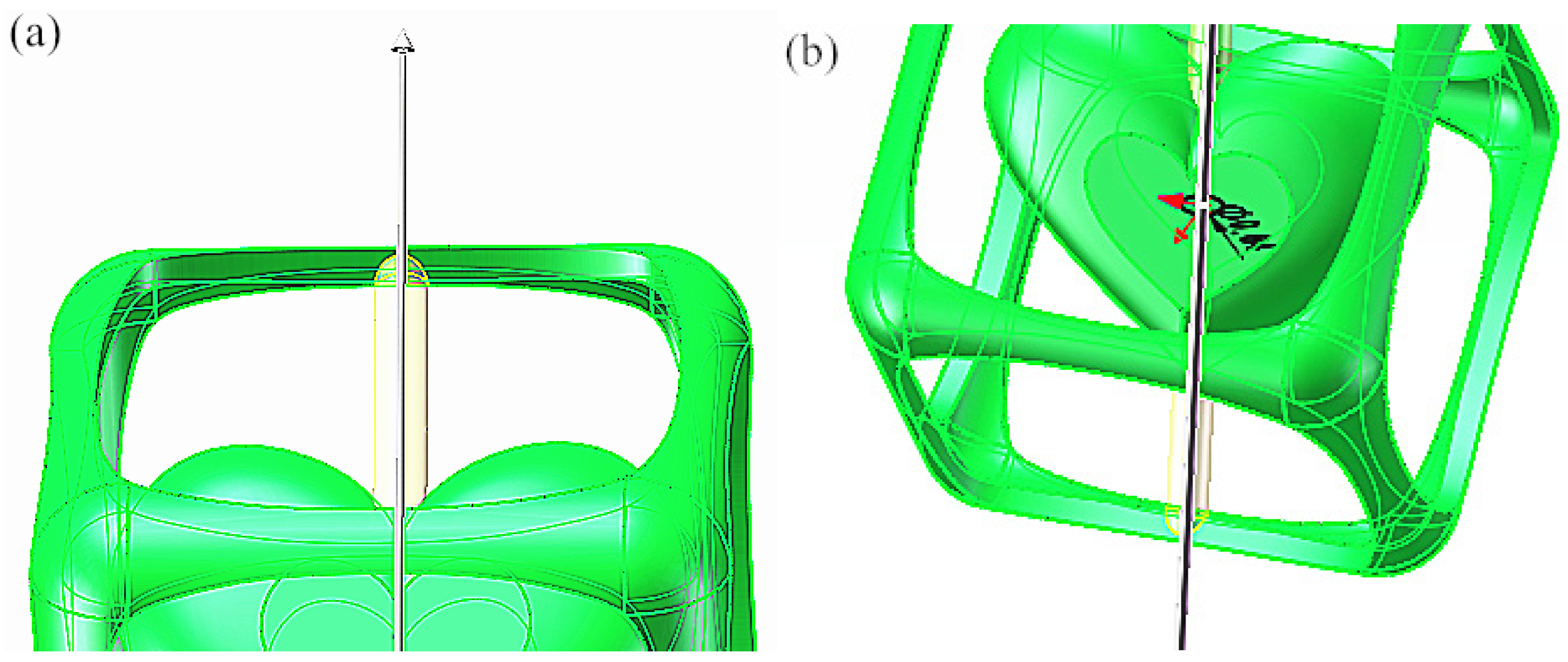
3.3.1. Examination of the 3D Jewelry Model

After finalizing the design of the “Guardian” jewelry 3D model using SolidWorks software, a thorough model check is essential before proceeding to the printing stage.
Entity check of the jewelry model: Navigate to Tools → Evaluation → Check option, selecting all entities and surfaces. Subsequently, identify and address any invalid faces and edges detected during the search to optimize and enhance the design.
Interference and surface curvature check of the jewelry model: Access Tools → Evaluate → Interference Check option and choose the jewelry assembly from the selected parts. Execute the interference calculation, confirming that there is no interference. This implies that the combined parts of the jewelry can be entirely printed based on the drawn model entity. To assess the smoothness of the jewelry surfaces, the curvature function was employed in the evaluation. The Guardian jewelry model exhibited a green color, except for the hexahedral corners marked in red. This signifies the excellent smoothness of the model surface, rendering it a complete and printable jewelry item, as depicted in Figure 8a.

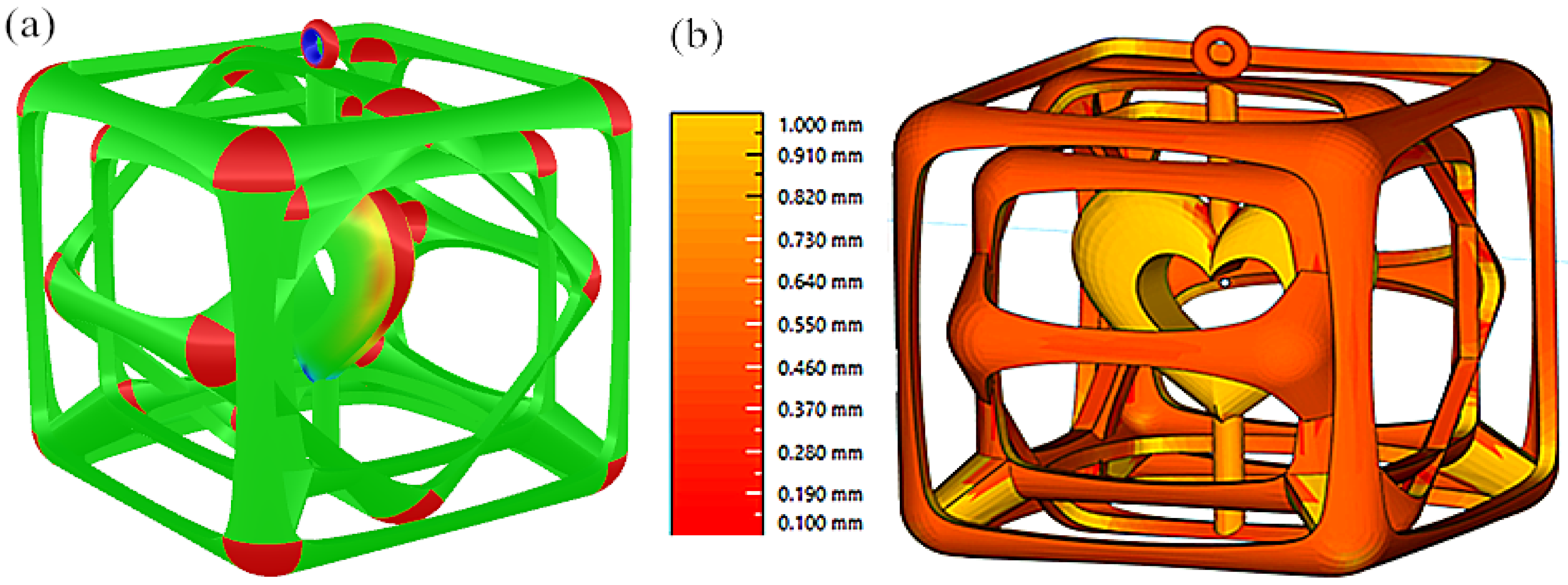
3.3.2. Wall Thickness Analysis of 3D Jewelry Models

To ensure the successful molding of the designed jewelry using the SLM machine, a wall thickness analysis was conducted on the “Guardian” jewelry model in Magics 22.0 software. Considering that the SLM molding equipment achieves better quality with parts having a width or thickness exceeding 0.1 mm, the minimum wall thickness was set to 0.1 mm and the maximum to 1 mm for the analysis. The results, depicted in Figure 8b, show that sections with widths or thicknesses below 0.1 mm appear in red, while those exceeding 1 mm are marked in yellow. Figure 8b shows that in the “Guardian” jewelry model, widths or thicknesses below 0.1 mm are represented in red, while those exceeding 1 mm are represented in yellow. All the widths or thicknesses of sharp corners and thin walls in the model are above 0.1 mm, meeting the SLM molding limit size requirements and ensuring a satisfactory molding outcome.

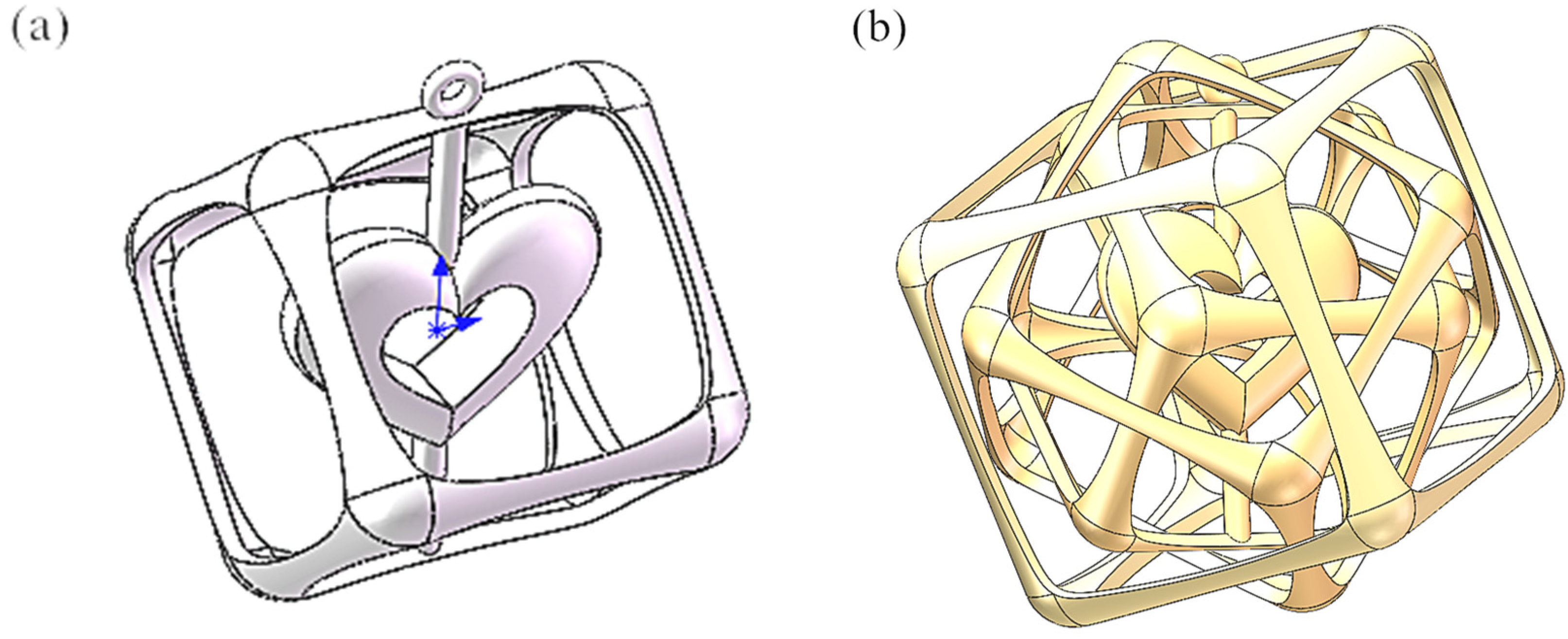
3.4. Data Processing for 3D-Printed Jewelry

The way support is added and placed for 3D-printed parts is related to the quality of the formed parts [13]. To gain deeper insights into the machining risk associated with the “Guardian” jewelry model, a comprehensive machining risk analysis was executed utilizing Magics software. Adhering to the stringent criteria of achieving a superior surface finish for the jewelry model and ensuring facile removal of support structures, a systematic adjustment of the positioning of the “Guardian” jewelry model relative to the substrate was carried out within the Magics software framework for thorough machining risk assessment. The optimized outcome is visually presented in Figure 9a. During the machining risk analysis, identifying specific areas in different colors indicates distinct support requirements. A red display denotes a necessitated addition of support, yellow signifies the requirement for support addition, and green indicates the absence of support necessity. Upon scrutiny of Figure 9a, post-adjustment of the model’s placement, it becomes evident that the imperative support zones are predominantly localized at the lower and upper extremities, with regions necessitating support being more widely distributed. Nevertheless, the unsupported areas are not extensive and are predominantly situated on the model’s surface, aligning seamlessly with the processing prerequisites of the jewelry model. Subsequently, wire support will be incorporated into the “Guardian” jewelry model following the completion of the machining risk analysis. The results of this support addition are elucidated in Figure 9b. A careful examination of Figure 9b reveals that the support additions for the “Guardian” jewelry model are concentrated primarily in non-critical regions where support removal is uncomplicated. Simultaneously, the volume of support addition is minimal, resulting in negligible powder waste—a practice consistent with the guiding principle of support addition for selectively laser-melted (SLM) molded parts.

3.5. Analysis of Results for the SLM “Guardian” Jewelry Model

The Selective Laser Melting (SLM)-fabricated “Guardian” jewelry is depicted in Figure 10. Upon a comprehensive visual inspection of the overall appearance of the “Guardian” jewelry in Figure 10, it is discerned that the jewelry’s surface exhibits a lustrous and pristine quality, accompanied by a commendable metal texture. Simultaneously, no conspicuous warping, deformation, or molding defects are evident. The structural integrity between the pillars is clearly defined, featuring well-executed lap joints. Furthermore, the jewelry demonstrates minimal powder adhesion. Additionally, the surface roughness of the “Guardian” jewelry was quantified through testing, yielding a measured roughness of 11 μm. This value suggests that following post-treatments such as sandblasting, polishing, and plating, the jewelry can be utilized directly.

4. Conclusions

  • The Guardian jewelry model, designed through the application of parametric modeling techniques, exhibits meticulous craftsmanship with no presence of invalid faces or edges. The model’s surfaces display a high degree of smoothness. All sharp corners in the model have a thin wall width or thickness of 0.1 mm or more, making it a complete jewelry accessory that can be printed.
  • The “Guardian” jewelry model exhibits a relatively extensive distribution of areas necessitating support, albeit not in terms of considerable size. Areas devoid of support requirements predominantly exist on the model’s surface, aligning with the processing standards for jewelry models. Support additions for the model predominantly concentrate in non-critical regions, where support removal is straightforward. The volume of added support is minimal, resulting in negligible powder waste. This adherence to minimal support addition aligns with the guiding principles for Selective Laser Melting (SLM) molding parts.
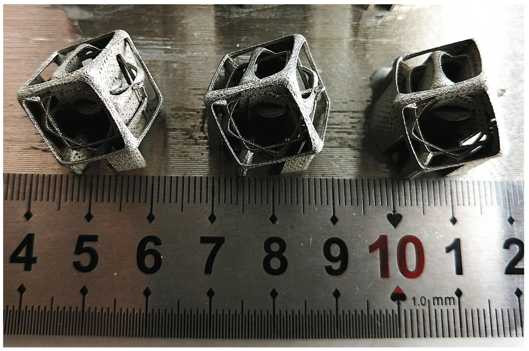
  • The completed, 3D-printed “Guardian” jewelry boasts a luminous and sleek surface characterized by a commendable metallic texture devoid of any discernible warping or molding defects. The pillars’ structure is distinct and exhibits well-executed lap joints, accompanied by minimal powder adhesion. After simple sandblasting and polishing, the jewelry is ready for use.
  • Certainly, to better align with people’s evolving design preferences in jewelry, further research endeavors are imperative. This includes the exploration of personalized and intricate rapid design methods for jewelry, self-supporting jewelry design techniques, and advancements in Selective Laser Melting (SLM) for the direct shaping of precious metals. Such investigations aim to establish the groundwork for the direct production of functional and personalized jewelry through SLM.

Author Contributions

Conceptualization: G.Z., Funding acquisition: G.Z., Investigation: G.Z., J.L., X.Z. and J.W., Formal analysis: G.Z. and Y.Z., Writing—original draft: G.Z. and Y.Z., Writing—review and editing: G.Z. All authors have read and agreed to the published version of the manuscript.

Funding

The study was funded by the Henan Provincial Science and Technology Project (232102311228, 242102311240) and the Open Project of Guangxi Key Laboratory of Regenerative Medicine (Guizai reopened 202202). Also, this work was supported by the Analytical and Testing Center of ZKNUC for carrying out analysis.

Institutional Review Board Statement

Not applicable.

Informed Consent Statement

Not applicable.

Data Availability Statement

The datasets used and/or analyzed during the current study are available from the corresponding author upon reasonable request.

Conflicts of Interest

The authors declare no conflicts of interest.

References

  1. Yu, J.; Zhang, T.; Bu, Y. Revision of total hip arthroplasty using uncemented extensive porous-coated femoral components. Chin. J. Orthop. 2005, 25, 110–114. [Google Scholar]
  2. Yuan, L.; Ding, S.; Wen, C. Additive manufacturing technology for porous metal implant applications and triple minimal surface structures: A review. Bioact. Mater. 2019, 4, 56–70. [Google Scholar] [CrossRef] [PubMed]
  3. Su, H.; Wei, K.; Guo, W.; Ma, L.; Yu, R.; Zhang, B.; Zhang, J.; Liu, L.; Fu, H. New development of laser rapid forming and its application in high performance materials processing. Chin. J. Nonferrous Met. 2013, 23, 1567–1574. [Google Scholar]
  4. Li, K.; Ji, C.; Bai, S.; Jiang, B.; Pan, F. Selective laser melting of magnesium alloys: Necessity, formability, performance, optimization and applications. J. Mater. Sci. Technol. 2023, 154, 65–93. [Google Scholar] [CrossRef]
  5. Zhang, G.; Li, J.; Shangguan, C.; Zhou, X.; Zhou, Y.; Huang, A. A metamaterial bone plate for biofixation based on 3D printing technology. Int. J. Bioprinting 2024, 2388. [Google Scholar] [CrossRef]
  6. Yang, J.; Heogh, W.; Ju, H.; Kang, S.; Jang, T.-S.; Jung, H.-D.; Jahazi, M.; Han, S.C.; Park, S.J.; Kim, H.S.; et al. Functionally graded structure of a nitride-strengthened Mg2Si-based hybrid composite. J. Magnes. Alloys 2024, 12, 1239–1256. [Google Scholar] [CrossRef]
  7. Ji, F.; Jin, Y. The application of 3D printing technology in jewelry design. West. Leather 2019, 41, 65. [Google Scholar]
  8. Zhang, W.; Zhao, H. Creative jewelry box design based on 3D printing technology. Technol. Innov. 2017, 5–7. [Google Scholar] [CrossRef]
  9. Yang, J.; Li, Y. 3D printed personalized ceramic pendant jewelry. J. Gemol. Gemol. 2018, 20, 201–203. [Google Scholar]
  10. Luo, J. Innovative application of 3D printing in weaving jewelry. Art Sci. Technol. 2017, 30, 286–287. [Google Scholar]
  11. Xiong, W.; Hao, L.; Li, Y. Application of selective laser melting (SLM) technology in jewelry activity structure design. J. Gemol. Gemol. 2018, 20, 194–195. [Google Scholar]
  12. Jia, J.; Sun, Z. Research on the design application of mortise and tenon structure in 3D printed jewelry. J. Gemol. Gemol. (Chin. Engl.) 2023, 25, 98–105. [Google Scholar]
  13. Zhang, G.; Yang, Y.; Zhang, Z.; Song, C.; Wang, A.; Yu, J. Optimum design of support structure for laser selective melting forming parts. China Laser 2016, 12, 59–66. [Google Scholar]
Figure 1. Microstructure of 316L alloy powder.
Coatings 14 00701 g001
Figure 2. Dimensions of hollow frame design.
Coatings 14 00701 g002
Figure 3. Cube hollow structure design: (a) appearance of the hollow structure; (b) the outermost cutting curve; (c) middle-layer cutting curve.
Coatings 14 00701 g003
Figure 4. Design of the internal “heart” model—(a) heart model; (b) outer heart contour line; (c) inner heart contour line.
Coatings 14 00701 g004
Figure 5. Generation of the heart-shaped model: (a) heart-shaped guide lines; (b) heart-shaped.
Coatings 14 00701 g005
Figure 6. The design of the “Guardian” jewelry framework: (a) the upper end of the framework; (b) the lower end of the architecture.
Coatings 14 00701 g006
Figure 7. “Guardian” jewelry model: (a) innermost layer model; (b) “Guardian” 3D model.
Coatings 14 00701 g007
Figure 8. Processability analysis of the “Guardian” jewelry model: (a) curvature analysis; (b) wall thickness analysis.
Coatings 14 00701 g008
Figure 9. Data processing of the “Guardian” jewelry model: (a) processing risk analysis; (b) support addition.
Coatings 14 00701 g009
Figure 10. SLM formed “Guardian” jewelry.
Coatings 14 00701 g010
Table 1. The comparison of powder material manufactured in SLM and ASTM A276 standard.
Element316L Powder (%)ASTM A276
Standard (%)
Element316L Powder (%)ASTM A276
Standard (%)
C<0.03<0.03Si<0.75<1.00
Mn<2.0<2.0P<0.025<0.045
S<0.01<0.03Cr17.5–1816–18
Ni12.5–1310–14Mo2.25–2.52–3
Cu0.500.75FeBalanceBalance
Disclaimer/Publisher’s Note: The statements, opinions and data contained in all publications are solely those of the individual author(s) and contributor(s) and not of MDPI and/or the editor(s). MDPI and/or the editor(s) disclaim responsibility for any injury to people or property resulting from any ideas, methods, instructions or products referred to in the content.

