Article

Effects of Dynamic Flow Rates on the In Vitro Bio-Corrosion Behavior of Zn-Cu Alloy

1
School of Materials Science and Engineering, Southeast University, Nanjing 211189, China
2
Jiangsu Key Laboratory for Advanced Metallic Materials, Southeast University, Nanjing 211189, China
3
Department of Physics, City University of Hong Kong, Hong Kong, China
4
Department of Materials Science and Engineering, City University of Hong Kong, Hong Kong, China
5
Department of Biomedical Engineering, City University of Hong Kong, Hong Kong, China
*
Author to whom correspondence should be addressed.
Coatings 2024, 14(6), 711; https://doi.org/10.3390/coatings14060711
Submission received: 15 April 2024 / Revised: 30 May 2024 / Accepted: 2 June 2024 / Published: 5 June 2024
(This article belongs to the Section Corrosion, Wear and Erosion)

Abstract

:
In the complicated real physiological environment in vivo, body fluids and blood are constantly replenished and move dynamically, and therefore, the dynamic impacts of bodily fluids and blood need to be considered in the evaluation of biodegradable materials. However, little research has been conducted on the impact of dynamic flowing circumstances on the corrosion characteristics of zinc-based alloys, particularly at high flow rates. The effects of various flow rates on the bio-corrosion behavior of the Zn-Cu alloy are thoroughly explored in this study. A model is developed using finite element analysis to investigate the impacts of flow rates and fluid-induced shear stress. The results reveal that the corrosion process of the Zn-Cu alloy is significantly accelerated by a higher flow rate, and a large fluid-induced shear stress caused by the boundary effect is found to promote corrosion. Furthermore, the empirical power function between the average flare rates in Hank’s solution and the corrosion rates of the Zn-Cu alloy is established by numerical simulation. The results provide insightful theoretical and experimental guidance to improve and evaluate the efficacy and lifespan of biomedical zinc-based alloy implants.

1. Introduction

Biodegradable metals are revolutionary biomedical materials and have been widely used in orthopedic, cardiovascular, gastrointestinal, and other systems in the past two decades [1,2]. Due to the characteristics of corroding and degrading in the human body, biodegradable metals do not need to be removed after service, which not only reduces the pain of patients but also avoids the risks and medical costs brought by secondary operations. Biodegradable metals are widely used in clinical operations [3,4,5,6]. Zinc-based alloys are considered potential biodegradable implant materials due to their ideal degradation rate, mild mechanical qualities, and good biocompatibility [7,8,9,10,11]. Furthermore, Zn is an essential element necessary for many metabolic activities. It also has moderate toxicity and promotes the development of new blood vessels during the healing process in corrosion products like ZnO and Zn(OH)2 [12]. For example, Bowen et al. [13] have established that Zn can mitigate cancer cell proliferation and prevent in-stent restenosis and found that the degradation process of zinc meets the requirements of degradable vascular stents. Dambatta et al. [14] evaluated the effect of heat treatment on microstructure, corrosion properties, and mechanical properties, and their in vivo and in vitro studies demonstrated that Zn-based alloys have acceptable biocompatibility as well as satisfactory mechanical capabilities.
To enhance the mechanical characteristics of zinc, copper (Cu) is a common alloying element [15,16,17]. The addition of copper enhances the strength and toughness of zinc via precipitation strengthening mechanisms, fine crystal strengthening, and solution strengthening [18,19]. As one of the essential micronutrients in the human body, Cu is closely related to the skeletal and cardiovascular systems, and copper has antibacterial effects that can mitigate infections after surgery [20,21,22]. Niu et al. [23] have observed that the extruded Zn-4Cu alloy has outstanding ductility and strength, suitable degradation, and significant antibacterial effects, making it well suited for cardiovascular applications. Compared with pure Zn, the Zn-Cu alloy has an elongation of more than 30%, which successfully meets the criteria for cardiovascular stent applications [24]. However, the Zn-4Cu alloy has some potential cytotoxicity against fibroblasts, as demonstrated by in vitro biocompatibility experiments [25]. Therefore, an excessively high concentration of Cu can pose biological hazards. The incorporation of an appropriate amount of Cu elements should be considered in the development of biomedical Zn-Cu alloys.
In the biomedical field, the corrosion resistance of implants is crucial because it is directly related to the service life of the implants. If the material corrodes too quickly in the body, it may lead to a decline in its mechanical properties and premature failure, which is not conducive to rehabilitation. If the corrosion rate is too slow, stress shielding will occur, leading to adverse reactions such as bone fragility and chronic inflammation. Therefore, the in-depth study and effective control of corrosion resistance are of key significance for improving the safety, effectiveness, and reliability of biomedical implants. At present, the biomedical field still faces some challenges, such as complex environments in vivo and appropriate corrosion rates. The environment inside the human body is very complex, including different liquids, flow rate, stress, composition, temperature, and pH value [26]. These factors will affect the corrosion performance of the biomedical implant. However, the majority of earlier research has been on static immersion experiments [27,28,29]. Blood and other flowing bodily fluids frequently come into contact with biodegradable metal implants, and the dynamic conditions in vivo may create different results than the static soaking conditions in vitro. Several researchers have studied the corrosion characteristics of magnesium alloys used in traditional Chinese medicine under dynamic flowing conditions, but similar studies on zinc alloys have seldom been reported [30,31,32]. Based on the different corrosion mechanisms of zinc alloy and magnesium alloy, it is crucial and necessary to evaluate the impacts of the dynamic physiological environment on zinc alloy corrosion comprehensively [33].
Herein, the relationship between the corrosion rates of the Zn-Cu alloy and the evolution of corrosion products under different fluid flow rates is assessed. Based on the experimental results, a model is established to predict the bio-corrosion rates of the Zn-Cu alloy under dynamic conditions.

2. Materials and Methods

2.1. Preparation of Materials

Using an AXxLMF15 direct reading spectrometer, the Cu content in the Zn-Cu alloy was found to be 0.10 ± 0.01 wt%. The alloy was separated into 10 mm × 10 mm × 2 mm samples, which were then ground using silicon carbide papers in the numbers #400, #600, #800, #1200, and #2000, and washed in ethanol and distilled water. To prevent galvanic corrosion, just an area of 1 × 1 cm2 was exposed, while the other surfaces were covered by silicone rubber.

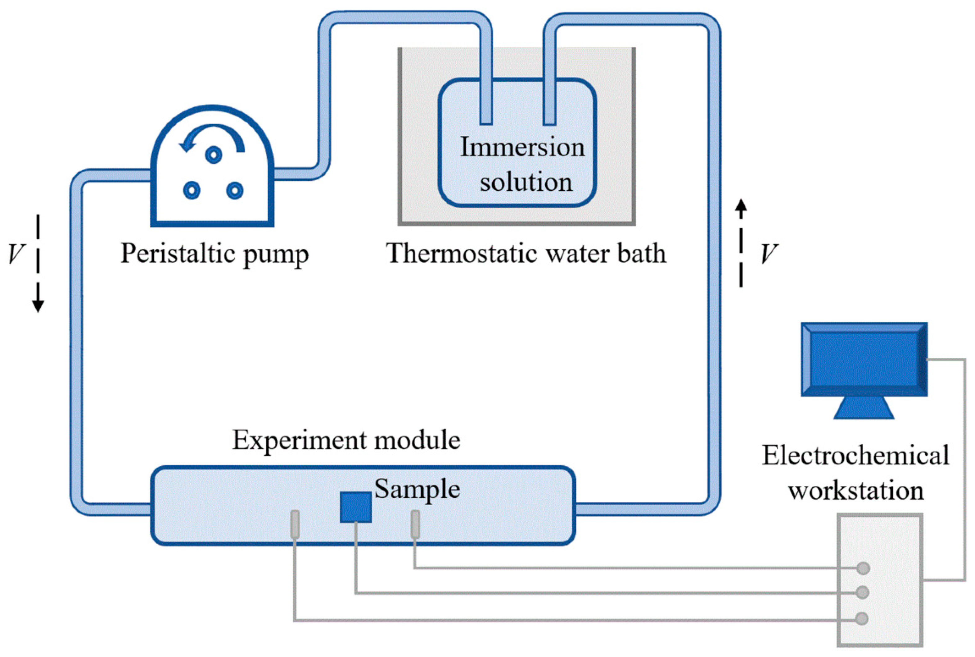
2.2. Immersion Tests

The dynamic measurement platform is established, as Figure 1 shows. The liquid storage tank was placed in a thermostatic water bath at 37 °C, and the sample was put in the central location of the experiment module. The immersion fluid selected Hank’s solution. The initial pH of Hank’s solution was regulated to 7.40 ± 0.05 at 37 ± 0.5 °C, and its composition is presented in Table 1. The immersion fluid was extracted from the storage tank and injected into a catheter by a peristaltic pump to imitate the physiological circumstances for various flow quantities in vitro. The flow quantities of the peristaltic pump were set at 0, 100, 200, 1000, and 2000 mL/min according to the internal environmental flow quantities. The fluid volume of 2 L was replenished at 24 h following the recording of pH values.

2.3. Materials Characterization

After immersion, the Zn-Cu samples were examined using optical microscopy and field-emission scanning electron microscopy (FE-SEM, FEI, Sirion 200, Hillsboro, OR, USA) at an acceleration voltage of 20 kV to assess the surface morphology and microstructure. Phase identification of the corrosion products generated on the surface was examined using X-ray diffraction (XRD, Bruker, D8-discover, Billerica, MA, USA). Energy-dispersive X-ray spectroscopy (EDS, Oxford, UK) was utilized to assess the elemental composition of the surface, and Fourier transform infrared spectrometry (FTIR, Nicolet iS10, Waltham, MA, USA, 400–4000 cm−1) was employed to examine the chemical structure.

2.4. Electrochemical Evaluation

Electrochemical impedance spectroscopy (EIS) of samples was tested by an electrochemical workstation (VersaSTAT 3F, Princeton, DE, USA) every 12 h. In order to achieve steady-state conditions during the in situ electrochemical testing, the dynamic loads were momentarily interrupted, and the open circuit test (OCT) was performed. The saturated calomel electrode (SCE), Pt electrode, and sample were utilized as the reference, counter, and working electrodes, respectively. The potential amplitude was 0.01 V, and the frequencies ranged from 100 kHz to 0.1 Hz. The Tafel curves were captured between −0.25 V vs. OC and 0.25 V vs. OC at a constant scan rate of 1 mV/s. The ZView2 software was used to analyze and fit the impedance spectra from three parallel tests.

2.5. Statistical and Finite Element Analyses

The Origin 8.5 software (Originlab Corporation, Wellesley Hills, MA, USA) was used to analyze and plot the data. The data presented in this study are the mean values obtained from three independent experiments, and a fitting procedure was conducted to determine the correlation. The finite element method implemented in ANSYS Workbench 15.0 was used to study the flow traces and shear stress distributions under flowing conditions. The model was established based on the shape of the experiment module in the flowing environment, and the flow quantities of the sample surface were calculated according to the different velocities set by the peristaltic pump. Fluid flow (CFX) was used to simulate the flow rates and velocity traces of the fluid. The viscosity of the fluid was 0.78 mPa, and the density was 0.99 g/cm3 at 37 °C.

3. Results

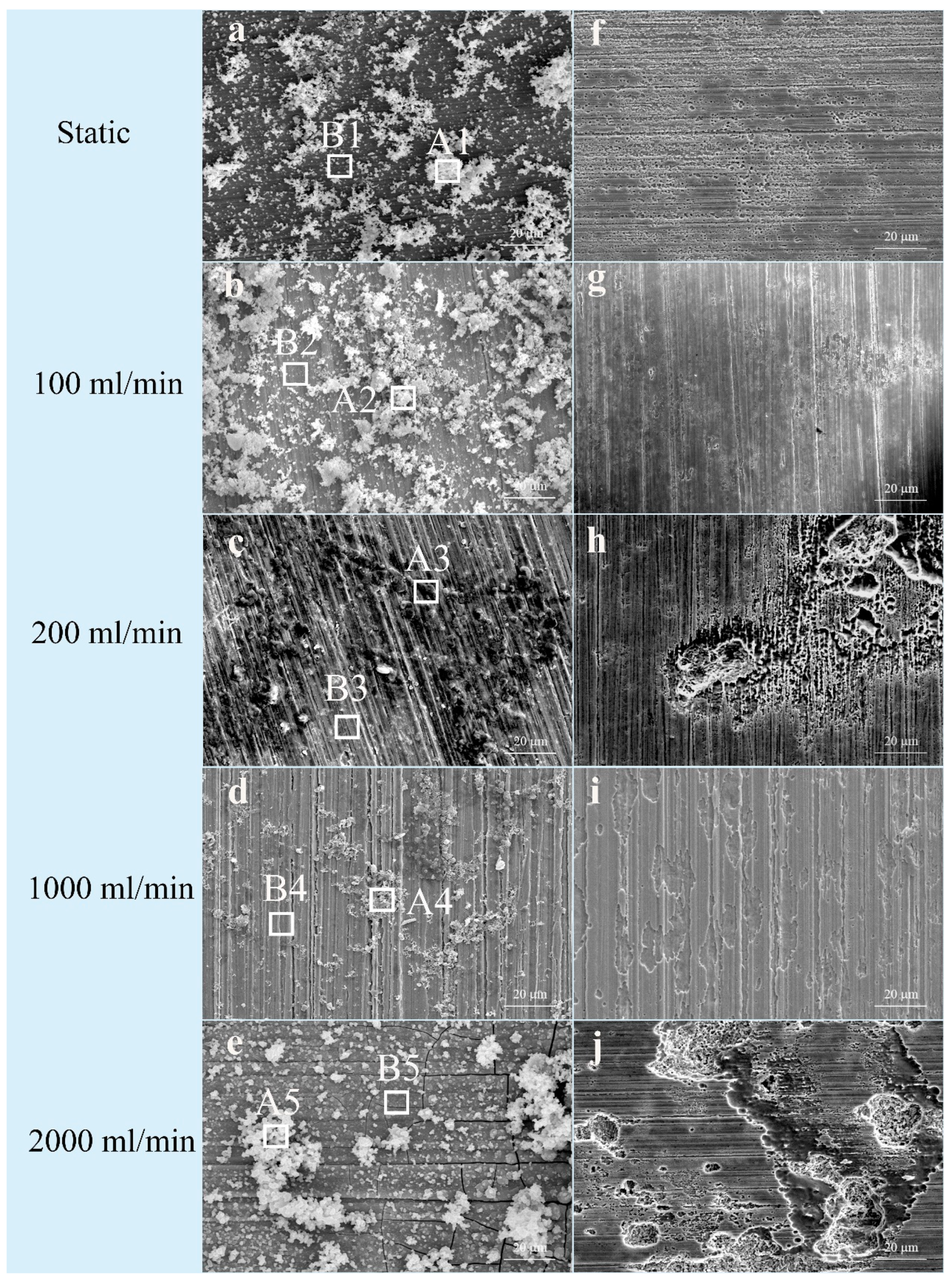
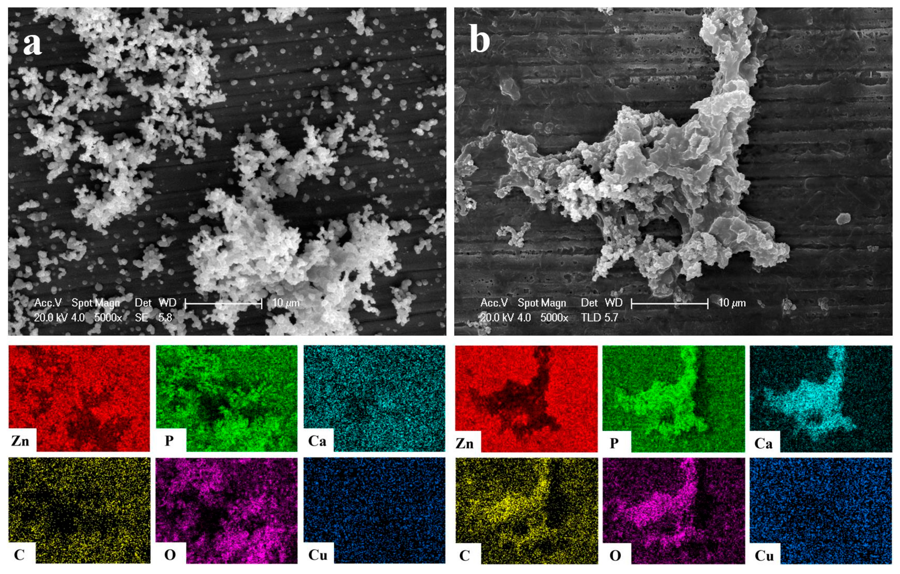
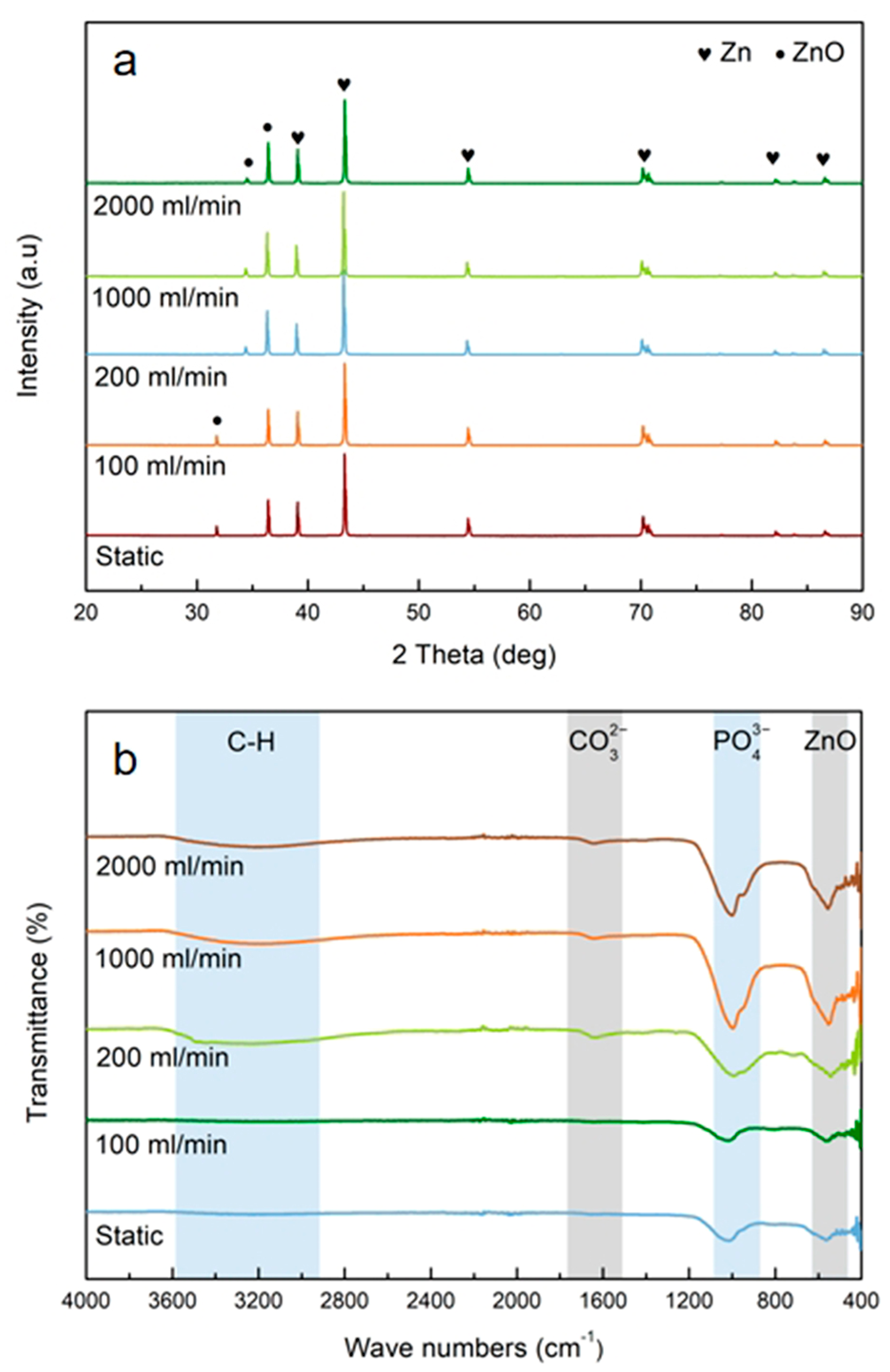
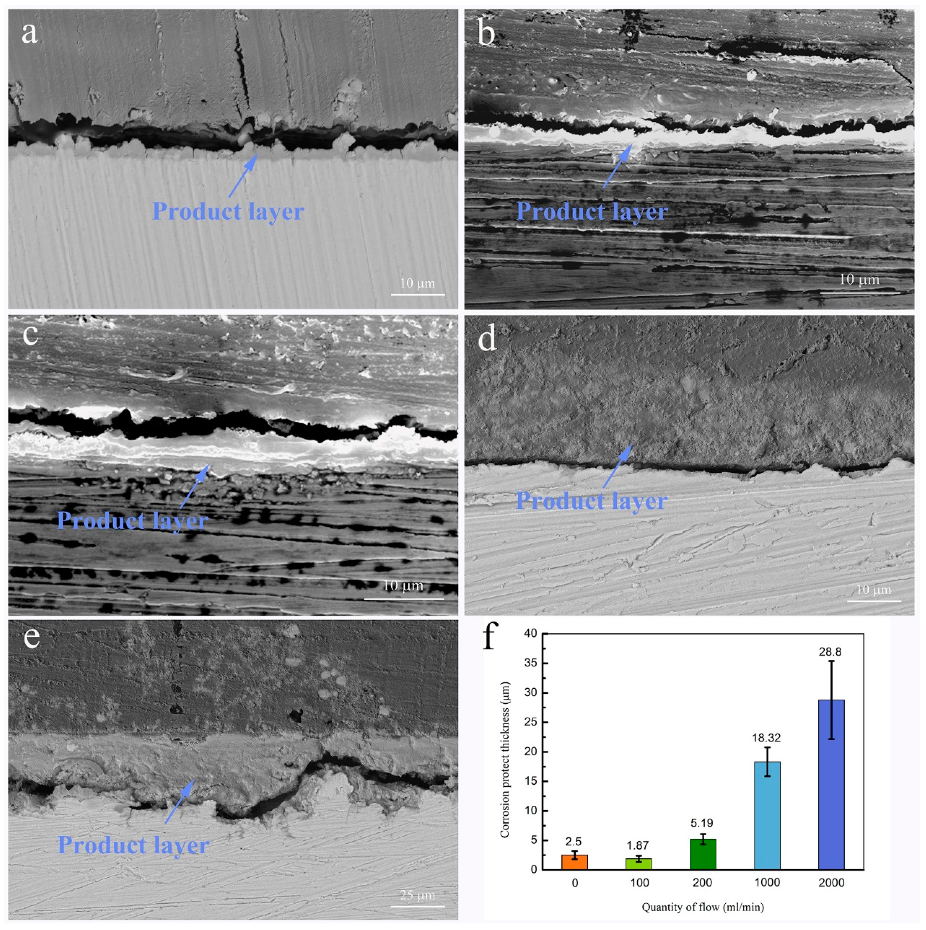
3.1. Morphology and Chemical Composition

Figure 2a–e displays the morphologies of the corrosion products that were deposited on the Zn-Cu samples’ inner surface. White granular corrosion products emerge from the sample surface after immersion for 120 h, and the coverage area changes depending on the flow quantity in Hank’s solution. A tiny amount of corrosion products loosely collects on the surface in the static environment (Figure 2a), but when the flow quantity is increased to 100 mL/min, the corrosion products increase (Figure 2b). However, as the flow quantity continues to increase, the loose granular corrosion products are washed away, leaving a denser corrosion layer, as shown in Figure 2c,d.
Chromium acid is used to detach the corrosion products in order to observe the surface morphology after corrosion (Figure 2f–j). In the static environment, shallow corrosion pits appear from the surface (Figure 2f). As the flow quantities go up, the area of the corrosion pits increases, and they join together in some areas (Figure 2g,h). With increasing flow quantities, erosion and corrosion are observed. When the flow quantity is 1000 mL/min, many corroded areas are observed along the direction of the liquid flow (Figure 2i). When the flow quantity is 2000 mL/min, corrosion is more serious, as manifested by the corrosion area and depth. Concave valleys are observed on the surface of the Zn-Cu alloy, as shown in Figure 2j. When the flow quantity is 2000 mL/min, the particle size and area of the dense corrosion products and directional grooves are observed, indicative of erosion and corrosion.
The areas A1–A5 and B1–B5 in Figure 2 are characterized by EDS (Figure 3). Areas A1–A5 are the areas with more corrosion products, and B1–B5 are the areas with fewer corrosion products. The elemental concentrations are shown in Figure 3, which reveals the presence of Zn, O, C, P, and Ca. The Cu content is insufficient, making it difficult to discern in the Figure 3. The overall proportions of Ca, P, C, and O in the corrosion products increase from zone A1 to zone A5, while that of Zn decreases, indicating that the amount of corrosion products increases with flow quantities. The proportion of Zn increases gradually from zones B1 to B5 because the surface phosphate and carbonate are washed away at higher flow quantities, so that ZnO is the main component on the surface. In addition, the overall proportions of C, P, and Ca in zones A1–A5 are bigger than those in zones B1–B5, indicating that the regions with more corrosion products have more phosphate, carbonate, and calcium compounds.
Figure 4 compares the elemental information of the corrosion products on the Zn-Cu samples that were immersed in Hanks’ solution with different flow quantities. Compared with the corrosion products in the static environment (Figure 4a), the structure of the corrosion products in the dynamic environment is denser, the corrosion products are more comprehensive, and the distribution of carbides is more concentrated.
Microscopy reveals severe corrosion at the edge of the sample in the flowing direction at a flow rate of 1000 mL/min. Figure 5b,c depict the enlarged A1 and A2 areas shown in Figure 5a, respectively, and the magnified A3 area is shown in Figure 2i. As the flow velocity changes, the degree of corrosion weakens, and the central corrosion area is relatively uniform.
After immersion for 120 h under different flowing conditions, XRD analysis is performed on the surfaces, and the findings are displayed in Figure 6a. The surfaces are mostly composed of ZnO and Zn, and there is no discernible change between the samples. This could be because the amorphous corrosion products are too thin to be detected by XRD. Figure 6b displays the Zn-Cu alloy’s FTIR spectrum. ZnO is associated with the peak at 541 cm−1, while the PO43− peak is seen at 994 cm−1. The broad band about 3220 cm−1 belongs to O−H, whereas the peak at 1637 cm−1 is linked to CO32−. Accordingly, zinc oxide, zinc hydroxide, zinc carbonate, and zinc phosphate make up the majority of the breakdown products’.
Figure 7 presents the cross-sectional morphology and corrosion product thickness of the Zn-Cu alloy after immersion. The static sample has a thin corrosion product layer with an average thickness of 2.50 ± 0.70 μm, whereas the 100 mL/min sample shows a thinner product layer because the flowing Hank’s solution hinders the accumulation of the corrosion product. Hence, the flowing Hank’s solution and contact with the corrosion products impact the formation of the corrosion products, and the flow conditions are unfavorable for the accumulation of corrosion products. At a flow quantity of 100 mL/min, corrosion product hindering predominates, and the corrosion product is thinner than the static sample. However, as the flow quantity is increased to 2000 mL/min, the average thickness of the corrosion product layer increases to 28.80 ± 6.61 μm, and it also becomes more uneven.

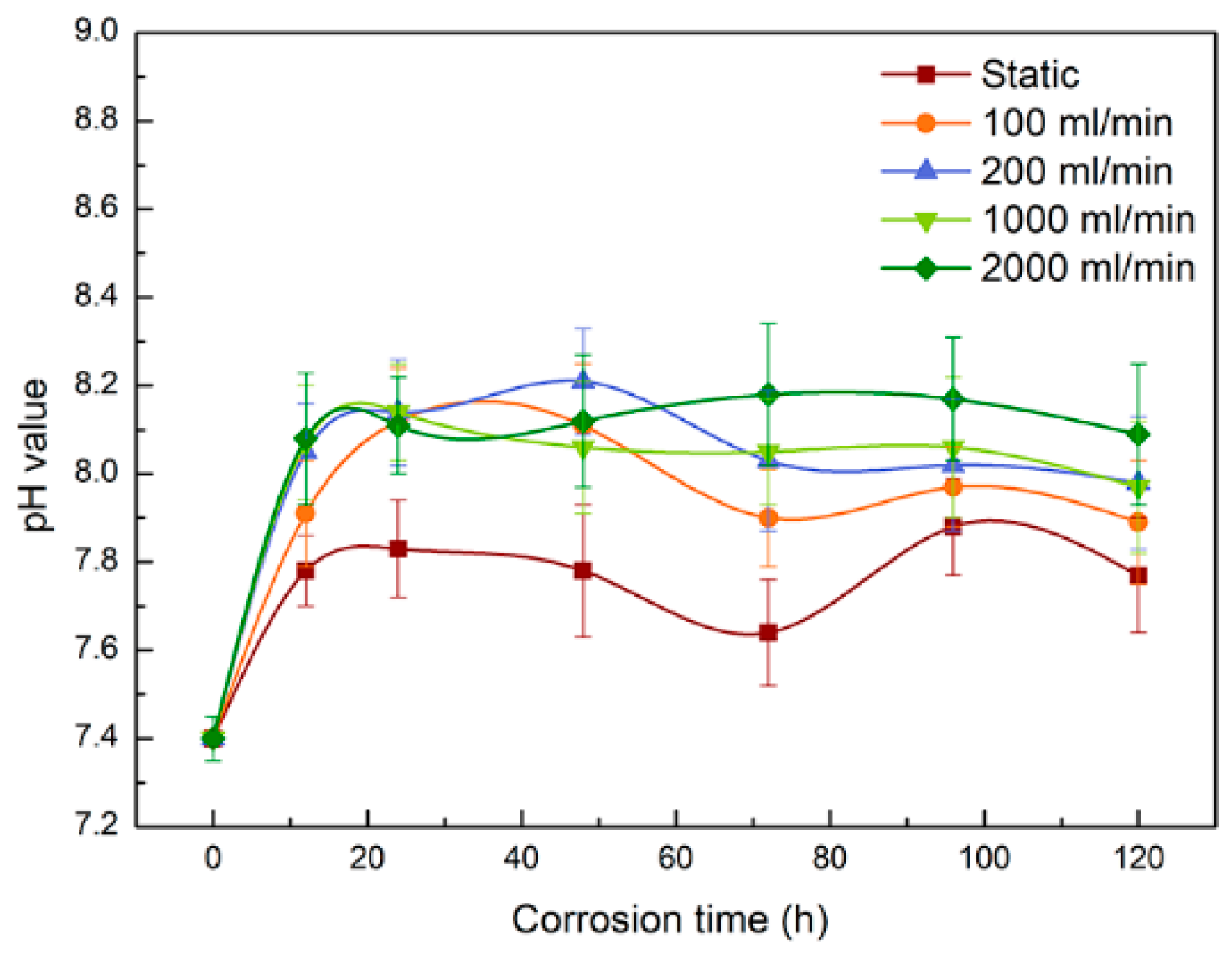
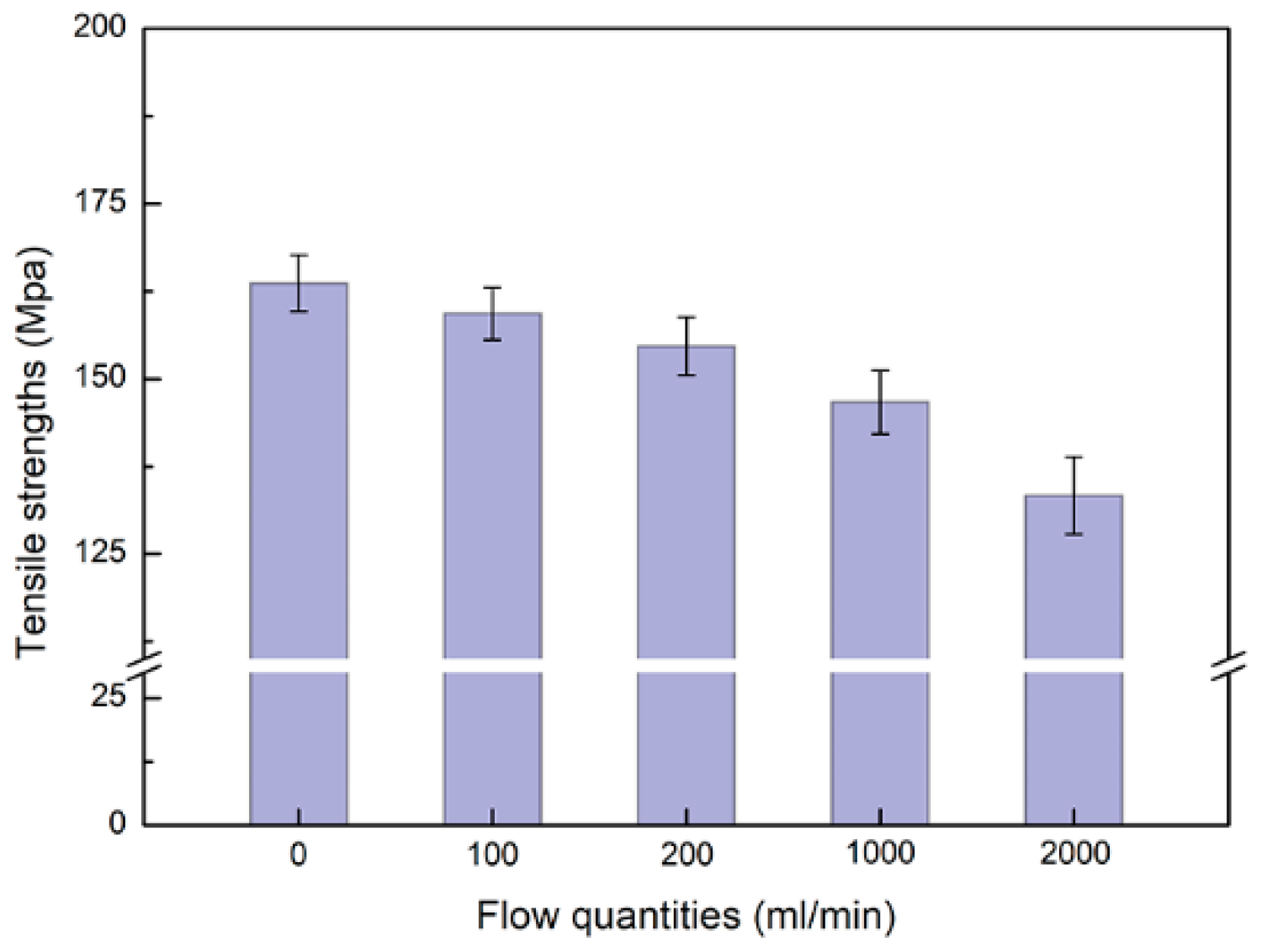
3.2. pH and Tensile Strength

Figure 8 displays the pH variations of Hank’s solution during the immersion test for different flow quantities. The pH values of Hank’s solution immersed with samples are higher than those of the initial Hank’s solution (7.40 ± 0.05) at each time point. However, as immersion continues, the pH values of the immersion solution in the late degradation period decrease compared with those in the early degradation period and then gradually become flat, indicating that the corrosion rate is fast initially but slows with time. By comparing the pH values under different flowing conditions, it can be observed that the higher the flow quantity, the greater the threshold for the pH increase, indicating that flowing accelerates the corrosion process during initial degradation.
Figure 9 depicts the Zn-Cu alloy’s mechanical characteristics after 120 h of degradation in Hank’s solution. Prior to the experiment, the tensile strength of the Zn-Cu alloy sample was determined to be 169 MPa before corrosion. After corrosion, the tensile strength is lower, and with increasing flow quantities, the tensile strength decreases. The variation of the tensile strength is similar to the pH change, and the higher the flow quantity, the more obvious the corrosion is.

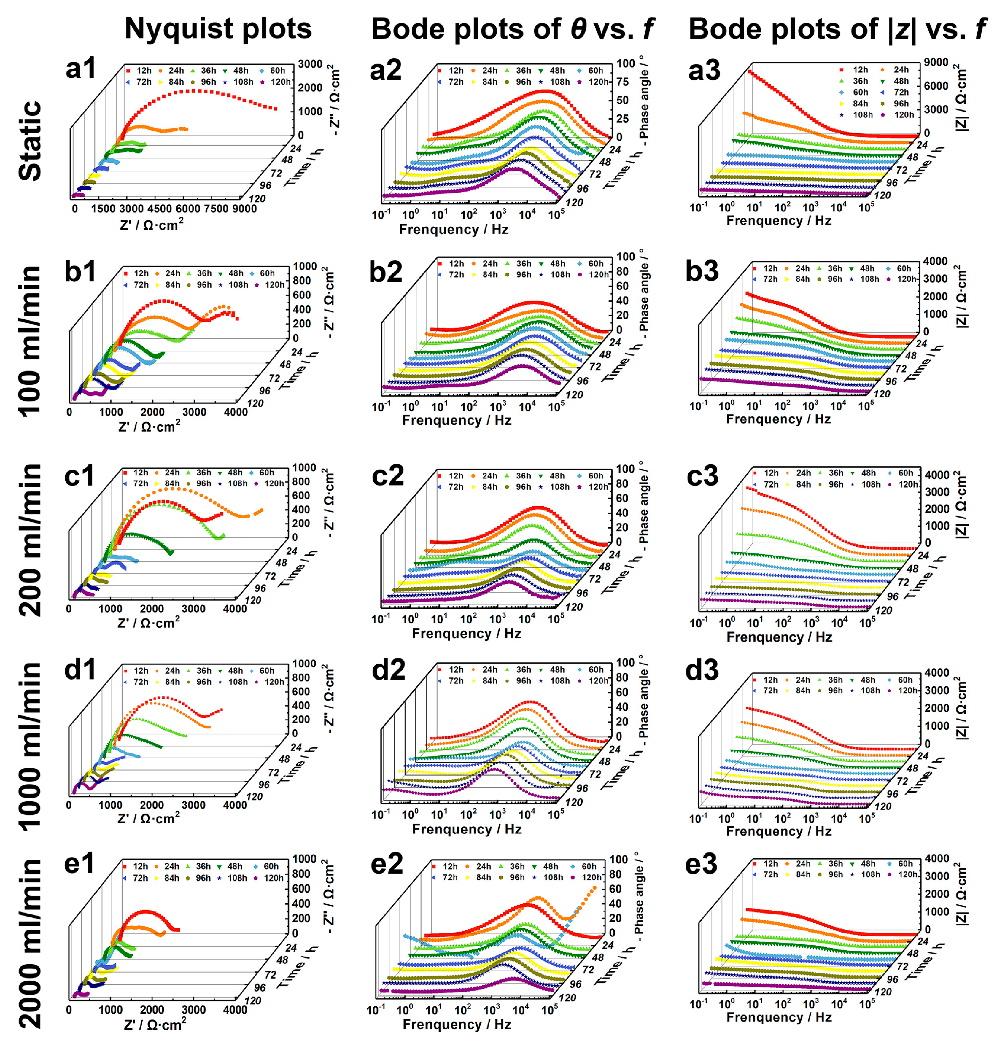
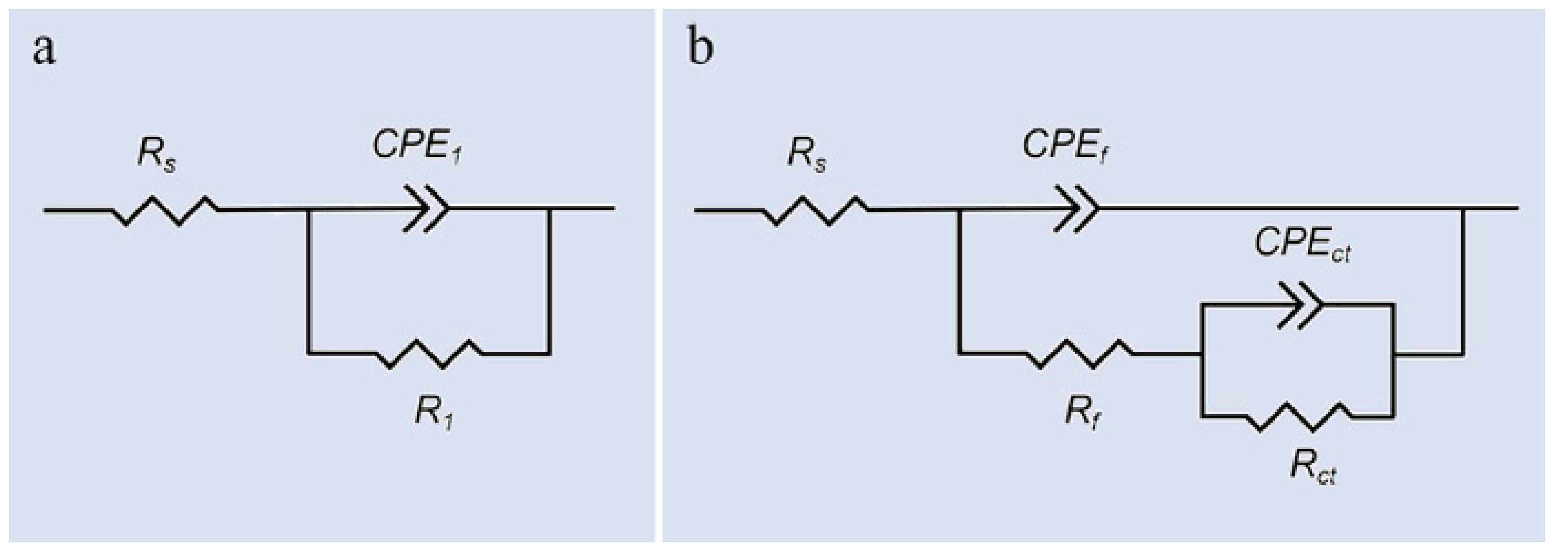
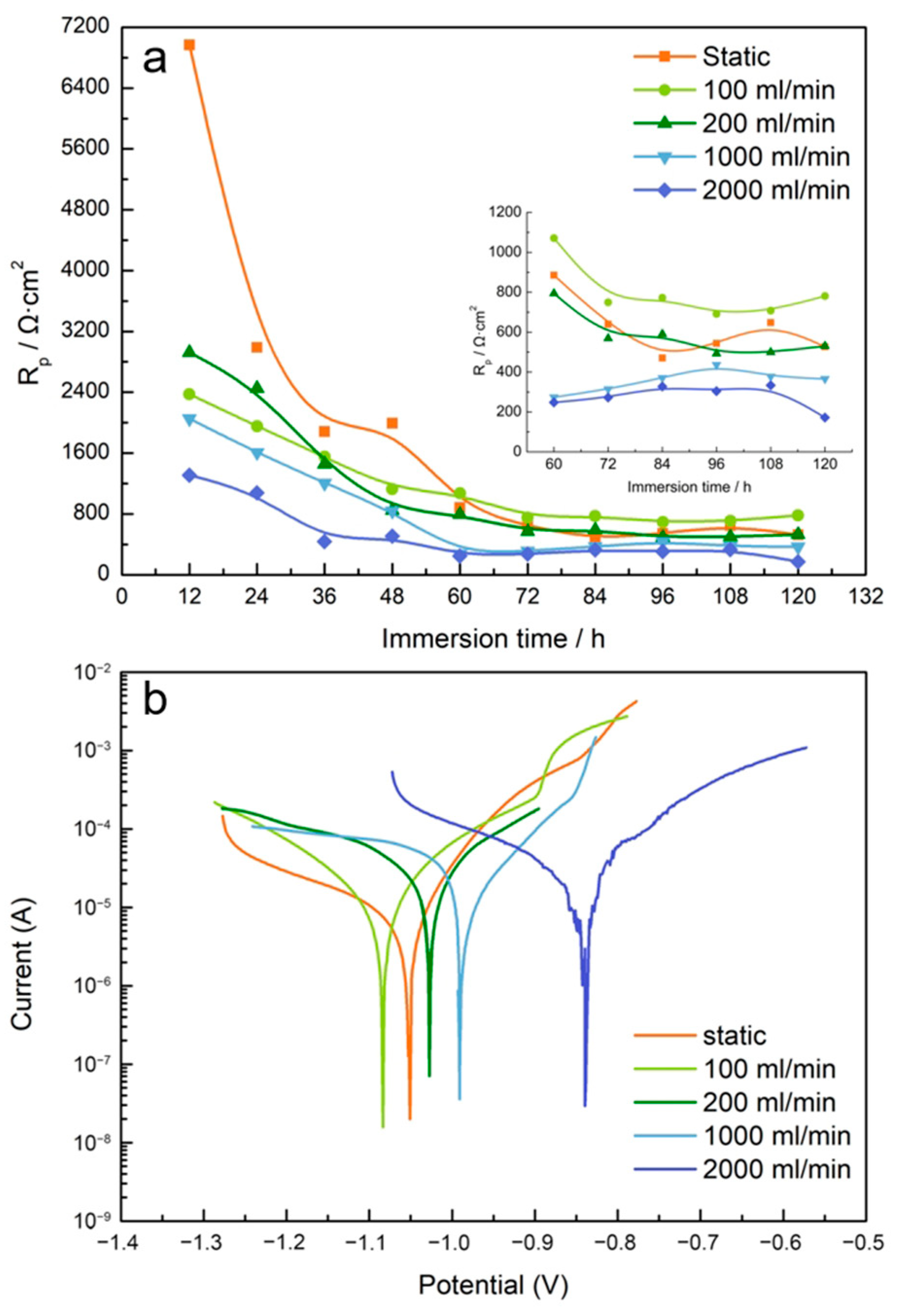
3.3. Electrochemical Assessment

The time-dependent EIS data under different dynamic flowing conditions are shown in Figure 10. With increasing immersion time, the diameter of the capacitive arc decreases in the Nyquist plots, and |Z|0.1 Hz is reduced in the Bode plots, indicative of declining corrosion resistance because the loose corrosion product layer cannot protect the samples. Because of the product layer and the concentration of corrosive ions in the stable later state, the capacitive arc’s diameter tends to become saturated with immersion time.
To analyze the EIS data, equivalent electrical circuits are used to fit the capacitive arc by the ZView2 software (Figure 11). In the initial stage (0–24 h), the impedance spectrum of the static sample shows one capacitive loop and one resistive loop. The equivalent circuit model in Figure 11a is proposed, where Rs is the solution resistance and R1 and CPE1 represent the polarization resistance (Rp) and capacitance of the corrosion product film, respectively. In the later period (36–120 h), a second capacitive loop and resistive loop appear, and the equivalent circuit model Rs(CPEf(Rf(CPEctRdl))) is shown in Figure 11b. It is composed of two time constants corresponding to the Rf-CPEf component in the middle frequency range with the corrosion product film resistance Rf and film constant phase angle element CPEf in parallel and the Rct-CPEdl component in the low frequency range with the charge transfer resistance Rct and double layer constant phase angle element CPEdl in parallel. The polarization resistance (Rp) reflects the kinetics of the corrosion process, as shown in Equation (1).
R p = R f + R c t
Figure 12a shows the change of Rp with time after fitting. In the initial 60 h of immersion, Rp decreases rapidly, suggesting that the corrosion rates increase quickly, resulting in corrosion product accumulation. Afterward, Rp stabilizes, implying that the corrosion product provides protection, and the protective and destructive effects reach a dynamic equilibrium. With increasing flow quantities, an overall downward trend is observed from Rp, indicating that a large flow quantity is beneficial to the corrosion of Zn-Cu alloys. However, the Rp value of the static samples is less than that of the 100 mL/min sample, probably because a small flow quantity does not favor the accumulation of the corrosion product. Hence, the thickness of the corrosion product at 100 mL/min is the smallest, as shown in Figure 7.
The Tafel curves after 120 h under dynamic flowing conditions are shown in Figure 12b, and Table 2 contains a list of the pertinent parameters. All of the anodic branches have passivation zones and resemblances to one another, which may be related to the buildup of corrosion products on their surfaces. In general, the self-corrosion potential (Ecorr) shifts to the left with flow quantities, indicating a higher flow quantity accelerates corrosion. The self-corrosion current (icorr) can be derived by Tafel extrapolation, and as the flow quantity increases, icorr increases, and corrosion is faster.

4. Discussion

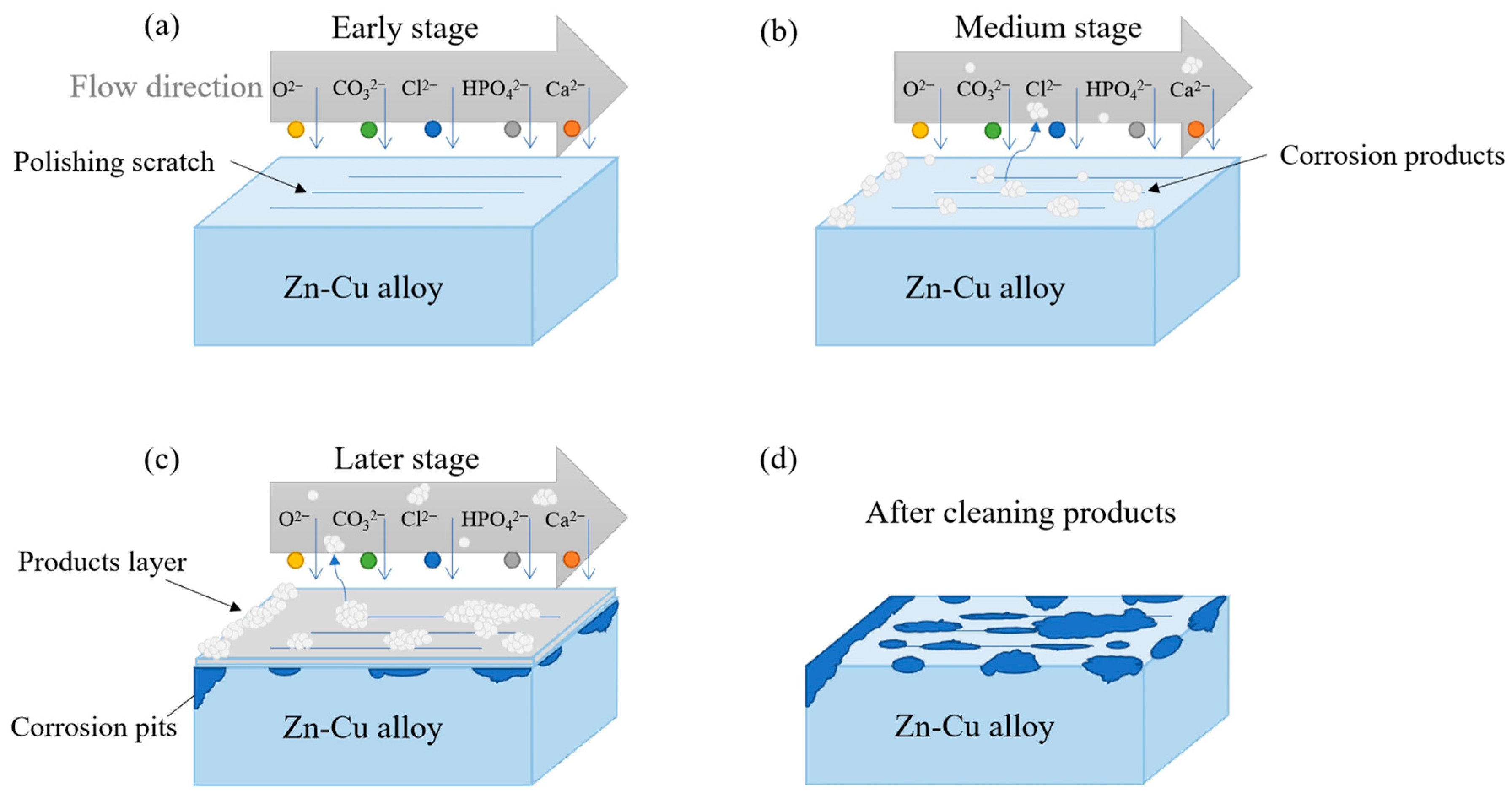
4.1. Corrosion Mechanism

Based on the experimental findings, the corrosion process of Zn-Cu occurs in distinct stages. Initially, the dissolution of the Zn-Cu alloy takes place through the following reactions [34,35,36]:
Zn → Zn2+ + 2e
Zn → Zn2+ + 2e
Zn2+ + CO32− → ZnCO3
3Zn2+ + 2PO43− → Zn3(PO4)2
Zn2+ + 2OH → Zn(OH)2
Zn(OH)2 → ZnO + H2O
The stability of Zn(OH)2 and ZnO is influenced by the presence of chloride, carbonate\bicarbonate, and phosphate ions in the surrounding medium, leading to the formation of compounds such as Zn3(PO4)2 and ZnCO3 [37,38].
In the initial stage, the diffusion process of erosive ions occurs mainly in the solution retention layer. The smooth surface of the sample is not conducive to the adhesion of erosive ions, besides the nucleation and growth of the corrosion products, resulting in fewer corrosion products. As shown in Figure 13b, the outer edges and inner scratches of the sample show stress concentration and are relatively rough during machining and processing. The erosive ions attach preferentially and react to form corrosion pits, which exhibit stress concentrations and spur nucleation to accelerate corrosion. As time elapses, a corrosion product composed of ZnO, Zn3(PO4)2, and ZnCO3 is formed on the surface (Figure 13c). In this stage, diffusion of erosive ions occurs in both the solution retention layer and corrosion product, and diffusion is affected by the thickness of the corrosion layer. Under static and slow-flowing conditions, the relatively stable corrosion layer inhibits corrosion, so the corrosion rate of the sample tends to be stable. Under fast-flowing conditions, some corrosion products are detached, and the exposed surface is damaged by repeated erosion and corrosion forming directional grooves, as shown in Figure 13d. More corrosion products are produced on the surface as a result of a high flow quantity’s simultaneous provision of a large volume of oxygen and quick erosive ion exchange rates. Therefore, the corrosion rate at a high flow quantity exhibits a dynamic trend.

4.2. Flow Rates

According to published research, fluid-induced shear stress (FISS) is one of the main factors in metal corrosion in a flow field environment [39,40]. Depending on the structure and shape of the implants, different materials are subjected to different shear forces in the flowing environment, and the local flowing patterns and velocities of fluids in different parts are also different, so the distribution of stress in different regions is not uniform. Based on the experimental conditions, ANSYS finite element modeling and fluid-structure coupling simulation are conducted to derive the velocity tracks under flowing conditions, as shown in Figure 14. When the fluid flows into the chamber through the entrance of the chamber, the velocity track diffuses, and the velocity decreases slightly due to the sudden change in the diameter of the pipe. When the fluid flows to contact the sample, it is hindered by the edge of the sample, and the flow state changes abruptly. Some of the fluid flows back, and the flow has a turbulent nature. Some of the fluid then crosses the edge of the sample and flows gently through the surface of the sample. The flow velocity is smaller than that at the edge, becoming a laminar flow. The flow velocity is not even, and that at the edge is higher than that at the middle of the sample.
The local equivalent velocity distribution of the flow-induced shear stress in the different parts of the apparatus is displayed in Figure 14c. In the experiment, the pump quantities are 0, 100, 200, 1000, and 2000 mL/min. The flow rates are different at different locations of the sample, and the equivalent flow rate decreases gradually along the direction of the fluid flow. According to the results of the finite element analysis, the average velocities at the locations are 0, 0.24, 0.47, 1.65, and 4.72 cm/s, respectively.

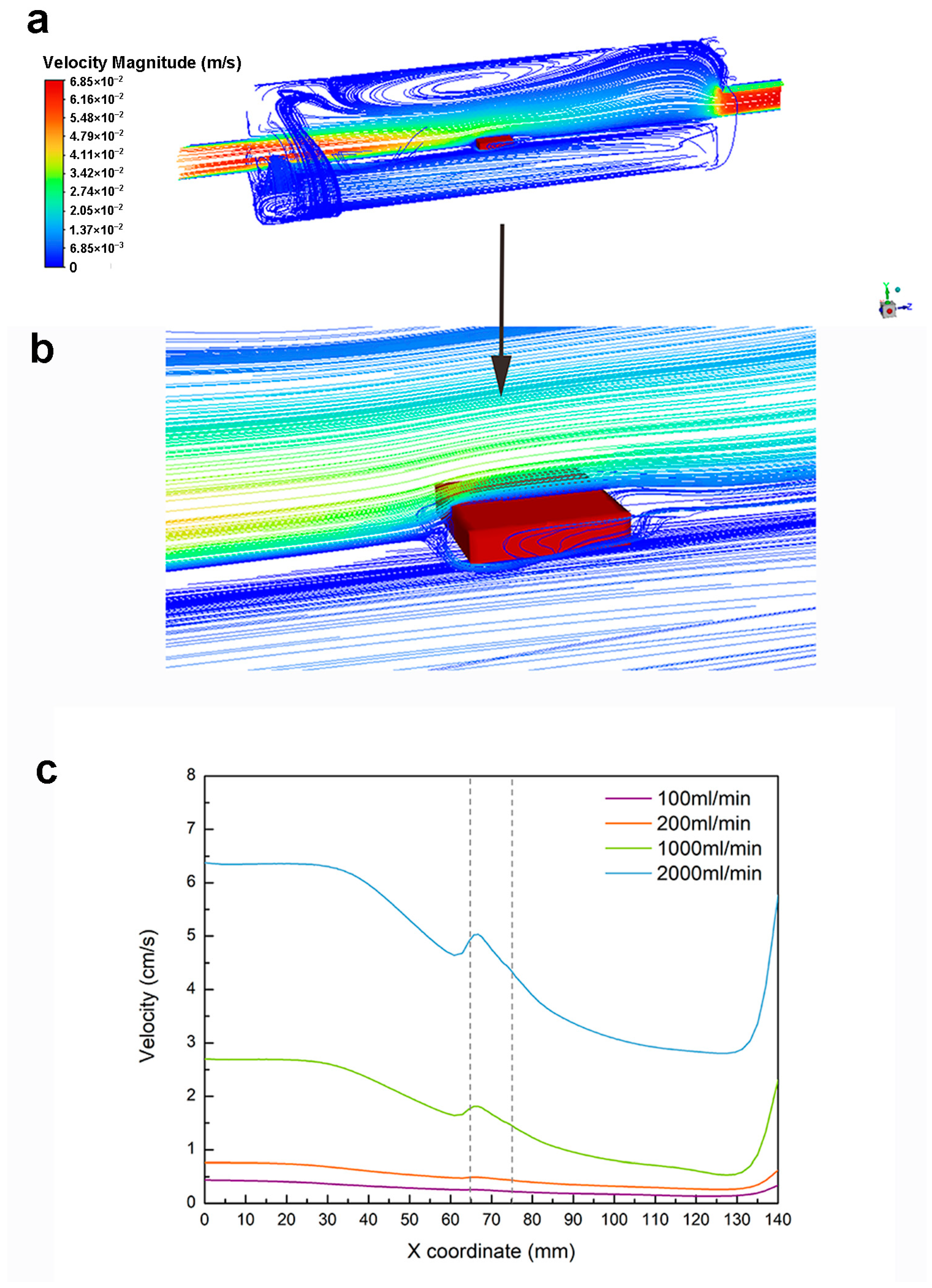
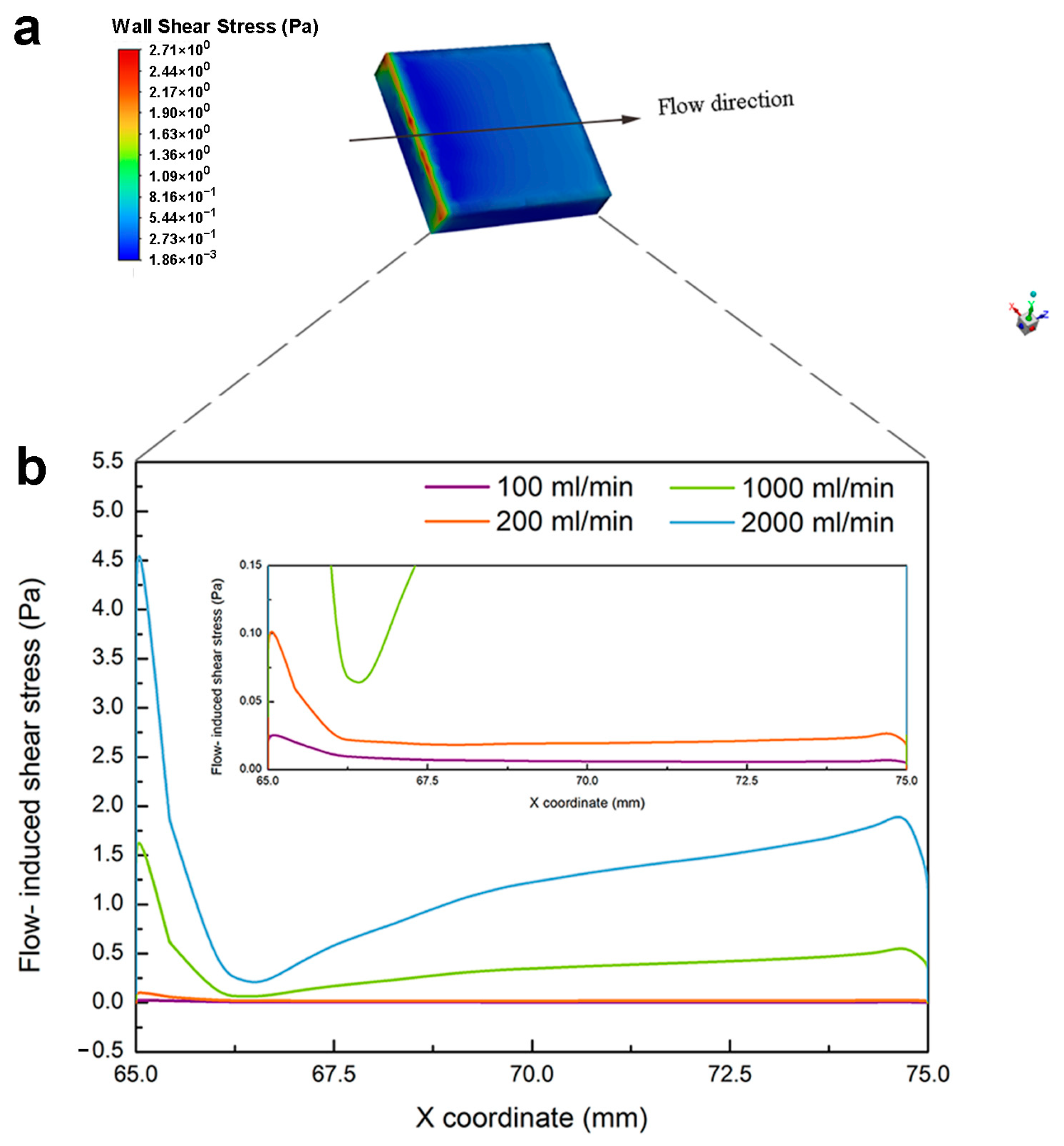
4.3. Flow-Induced Shear Stress

Figure 15a shows the simulated distributions of the flow-induced shear stress (FISS) at a flow quantity of 1000 mL/min. The finite element analysis reveals that the left edge, which faces the flow direction, has a very high FISS due to the boundary effect. A high FISS gives rise to stress corrosion, which is consistent with the corrosion morphology shown in Figure 5. As shown in Figure 15b, FISS increases with flow rates, and along the flowing direction, FISS gradually decreases and then stabilizes. The higher the flow quantities, the greater the flow-induced shear stress and the faster the corrosion rate. The possible reasons can be attributed to three main factors. Firstly, high-speed fluid flows may disrupt or remove protective corrosion product films or passivation films on metal surfaces, exposing them directly to corrosive environments and accelerating corrosion rates. Secondly, increased flow-induced shear forces can enhance local concentrations of oxygen or other corrosive components, promoting their arrival at metal surfaces while also hastening the removal of existing corrosion products that may speed up overall reaction rates. Finally, fluid shear forces may induce local stresses and strains on metal surfaces that alter microstructures and affect sensitivity to and rates of corrosion.

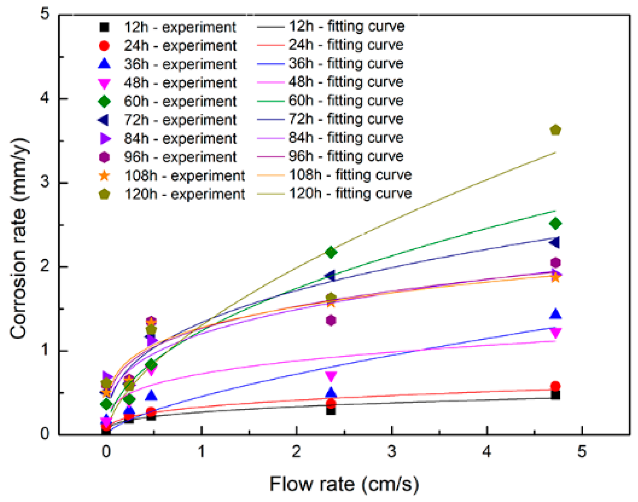
4.4. Corrosion Rates

The corrosion rate (CR) of the Zn-Cu alloy can be derived from the corrosion current density (icorr) in the EIS and Tafel data, and icorr is related to Rp as shown in the Stern formula below [41].
R p = b a b c 2.303 ( b a + b c ) i c o r r
where ba and bc are the anodic and cathodic Tafel slopes. The values of ba and bc are presented in Table 2, and icorr(EIS) can be determined from Rp in the fitted EIS data. The relationship between the corrosion rate (CR) and icorr is analyzed according to ASTM G59-97 as follows [42]:
C R = 8.76 × 10 4 i c o r r a N F ρ
where a represents the molar mass of the Zn-Cu alloy (65.324 g/mol), ρ indicates the density of the Zn-Cu alloy (g·cm−3), F is Faraday’s constant (26.8 Å h), and N denotes the number of electrons exchanged during the electrochemical reaction. According to Equation (9), the corrosion rate with immersion time at different flow rates can be obtained, as shown in Figure 16. Overall, the corrosion rate rises with flow rates, revealing that flowing promotes corrosion of the Zn-Cu alloy. At zero or small flow rates, the corrosion rate increases steadily with time. However, at a high flow rate, the corrosion rate fluctuates because the production of the corrosion product is dynamic and dictated by concurrent deposition and detachment.

4.5. Corrosion Model

The experimental results disclose a positive correlation between the flow rate and corrosion rate of the Zn-Cu alloy. The flow rate can be calculated by the flow rate and cross-sectional area of the fluid. The relationship between the average flow rate (v) and corrosion rate (CR) can be further clarified to satisfy the power function by fitting. The corrosion model is shown in the following:
C R = α · v β
where α and β vary with the corrosion time, as shown in Table 3. Figure 17 depicts the experimental corrosion rate (CR) and corresponding fitted values for various v during immersion for 120 h, demonstrating a strong concordance between the empirical and modeled outcomes.
Figure 17 shows that in the first 24 h, the average flow rate has little influence on the corrosion rate of the Zn-Cu alloy. This is because in the initial corrosion stage, few corrosion products are generated, and the layer is relatively thin. In addition, diffusion of erosive ions mainly occurs on the surface retention layer. As corrosion proceeds, the quantity of corrosion products increases, leading to their accumulation on the surface and the formation of a layer. In this stage, diffusion of erosive ions occurs in both the solution retention layer and corrosion product layer, and it is affected by the thickness of the corrosion layer. Therefore, the corrosion rates differ at different average flow rates.
In summary, the effects of flow velocity and soaking time on the corrosion of zinc alloy in the dynamic environment were analyzed by means of micro-surface morphology, cross-sectional morphology, electrochemical testing, and so on. The main conclusions are as follows: Firstly, the longer the soaking time, the faster the corrosion rate. This is due to the accumulation of corrosion products and the increase in erosion ion concentration as the corrosion time increases. Secondly, the higher the flow rate, the greater the flow-induced shear stress and the faster the corrosion rate. The main reasons are the flow-induced shear stress that can disrupt the corrosion product film on the metal surface, leading to direct exposure of the metal to corrosive environments. Meanwhile, flow fluids increase local concentrations of oxygen or other corrosive components on sample surfaces while also promoting the removal of corrosion products, thereby expediting corrosion reactions. Additionally, fluid-induced shear forces may induce local stress and strain on metal surfaces, resulting in microstructural changes that subsequently impact corrosion rates.
The corrosion rate of zinc alloy is between that of iron alloy and magnesium alloy, and it is very feasible as a human implant material [34]. After the metal implants are placed in the body, endothelialization will be completed within weeks and months, depending on the size of the implant, its location, and individual immunological variations. Yang et al. [6] placed pure zinc stents into rabbit abdominal aortas in 12 months. They discovered the evolution of the deterioration mechanism of pure zinc stents over time, i.e., dynamic blood flow dominated the deterioration of pure zinc stents before endothelialization; after endothelialization, the degradation of pure zinc stents was dependent on the diffusion of water molecules, hydrophilic solutes, and ions. Hence, before the artery implant has been encased within neointimal tissue, flow conditions have a direct impact on it. After endothelialization, the effect of fluid velocity on ion diffusion and flow-induced stress can both affect the corrosion of zinc alloys. Consequently, our study’s findings primarily have direct guiding implications for how bioabsorbable stents will behave in the early implantation stage prior to endothelialization, and the diffusion of erosive ions is indirectly influenced by the fluid velocity after endothelialization.

5. Conclusions

The effects of the dynamic flow rate of Hank’s solution on the bio-corrosion behavior of the Zn-Cu alloy are determined. After immersion, the main corrosion products are ZnO, Zn(OH)2, and ZnCO3, as well as a small amount of calcium–phosphorus compounds. In the dynamic flowing environment, corrosion of the Zn-Cu alloy is accelerated by the flowing solution. In the middle of the sample surface, corrosion ions preferentially adhere to the scratches, resulting in spot corrosion, and erosion corrosion is observed with increasing flow rates. The flow rate affects the distribution of FISS on the surface of the alloy. Compared to the inner area, a higher FISS is observed from the edge in the flowing direction due to the boundary effect. Because of stress corrosion, high FISS can lead to severe corrosion at the edge, which can impact the lifetime of the biomedical implants. By means of numerical simulation, a power function is established to elucidate the relationship between the average flow velocity (v) and the corrosion rate (CR) of the Zn-Cu alloy. The empirical relationship is determined to be  C R = α · v β . Our results provide insights into the corrosion characteristics of the Zn-Cu alloy and provide guidance in the design of biodegradable biomedical implants.

Author Contributions

Conceptualization, X.Z. and L.H.; methodology, L.H.; software, X.Z.; validation, X.Z.; investigation, X.Z. and L.Z.; resources, J.B., Z.H. and C.G.; data curation, X.Z.; writing—original draft preparation, X.Z.; writing—review and editing, P.K.C. and L.Z.; supervision, C.C. and F.X.; project administration, C.C. All authors have read and agreed to the published version of the manuscript.

Funding

This work was supported by the National Natural Science Foundation of China (Grant No. 52171236), State Key Program of the National Natural Science Foundation of China (Grant No. 52231005), Suzhou Science and Technology Project (SJC 2023005, SZC2023023), Open Research Fund of Jiangsu Key Laboratory for Advanced Metallic Materials, Southeast University (Grant No. AMM2024A01), Postgraduate Research and Practice Innovation Program of Jiangsu Province (Grant No. KYCX20_0091), as well as City University of Hong Kong Donation Research Grants (Grant Nos. 9220061 and DON-RMG 9229021).

Institutional Review Board Statement

Not applicable.

Informed Consent Statement

Not applicable.

Data Availability Statement

The raw/processed data required to reproduce these findings cannot be shared at this time as the data also form part of an ongoing study.

Conflicts of Interest

The authors declare no conflicts of interest.

References

  1. Al-Shalawi, F.D.; Hanim, M.A.A.; Ariffin, M.K.A.; Kim, C.L.S.; Brabazon, D.; Calin, R.; Al-Osaimi, M.O. Biodegradable synthetic polymer in orthopaedic application: A review. Mater. Today Proc. 2023, 74, 540–546. [Google Scholar] [CrossRef]
  2. Zheng, Y.F.; Gu, X.N.; Witte, F. Biodegradable metals. Mater. Sci. Eng. R Rep. 2014, 77, 1–34. [Google Scholar] [CrossRef]
  3. Huang, S.; Wu, W.; Su, Y.; Qiao, L.; Yan, Y. Insight into the Corrosion Behaviour and Degradation Mechanism of Pure Zinc in Simulated Body Fluid. Corros. Sci. 2021, 178, 109071. [Google Scholar] [CrossRef]
  4. Li, H.; Yang, H.; Zheng, Y.; Zhou, F.; Qiu, K.; Wang, X. Design and Characterizations of Novel Biodegradable Ternary Zn-based Alloys with IIA Nutrient Alloying Elements Mg, Ca and Sr. Mater. Des. 2015, 83, 95–102. [Google Scholar] [CrossRef]
  5. Liu, L.; Meng, Y.; Dong, C.; Yan, Y.; Volinsky, A.A.; Wang, L. Initial Formation of Corrosion Products On Pure Zinc in Simulated Body Fluid. J. Mater. Sci. Technol. 2018, 34, 2271–2282. [Google Scholar] [CrossRef]
  6. Yang, H.; Wang, C.; Liu, C.; Chen, H.; Wu, Y.; Han, J.; Jia, Z.; Lin, W.; Zhang, D.; Li, W.; et al. Evolution of the Degradation Mechanism of Pure Zinc Stent in the One-Year Study of Rabbit Abdominal Aorta Model. Biomaterials 2017, 145, 92–105. [Google Scholar] [CrossRef] [PubMed]
  7. Hernández-Escobar, D.; Champagne, S.; Yilmazer, H.; Dikici, B.; Boehlert, C.J.; Hermawan, H. Current status and perspectives of zinc-based absorbable alloys for biomedical applications. Acta Biomater. 2019, 97, 1–22. [Google Scholar] [CrossRef] [PubMed]
  8. Mostaed, E.; Sikora-Jasinska, M.; Drelich, J.W.; Vedani, M. Zinc-Based Alloys for Degradable Vascular Stent Applications. Acta Biomater. 2018, 71, 1–23. [Google Scholar] [CrossRef] [PubMed]
  9. Bowen, P.K.; Drelich, J.; Goldman, J. Zinc Exhibits Ideal Physiological Corrosion Behavior for Bioabsorbable Stents. Adv. Mater. 2013, 25, 2577–2582. [Google Scholar] [CrossRef]
  10. Li, G.; Yang, H.; Zheng, Y.; Chen, X.; Yang, J.; Zhu, D.; Ruan, L.; Takashima, K. Challenges in the Use of Zinc and its Alloys as Biodegradable Metals: Perspective from Biomechanical Compatibility. Acta Biomater. 2019, 97, 23–45. [Google Scholar] [CrossRef]
  11. Liu, X.; Sun, J.; Yang, Y.; Pu, Z.; Zheng, Y. In Vitro Investigation of Ultra-Pure Zn and its Mini-Tube as Potential Bioabsorbable Stent Material. Mater. Lett. 2015, 161, 53–56. [Google Scholar] [CrossRef]
  12. Ahtzaz, S.; Nasir, M.; Shahzadi, L.; Amir, W.; Anjum, A.; Arshad, R.; Iqbal, F.; Chaudhry, A.A.; Yar, M.; Rehman, I.U. A Study on the Effect of Zinc Oxide and Zinc Peroxide Nanoparticles to Enhance Angiogenesis-Pro-Angiogenic Grafts for Tissue Regeneration Applications. Mater. Des. 2017, 132, 409–418. [Google Scholar] [CrossRef]
  13. Bowen, P.K.; Guillory, R.J.; Shearier, E.R.; Seitz, J.; Drelich, J.; Bocks, M.; Zhao, F.; Goldman, J. Metallic Zinc Exhibits Optimal Biocompatibility for Bioabsorbable Endovascular Stents. Mater. Sci. Eng. C 2015, 56, 467–472. [Google Scholar] [CrossRef] [PubMed]
  14. Dambatta, M.S.; Izman, S.; Kurniawan, D.; Farahany, S.; Yahaya, B.; Hermawan, H. Influence of Thermal Treatment on Microstructure, Mechanical and Degradation Properties of Zn–3Mg Alloy as Potential Biodegradable Implant Material. Mater. Des. 2015, 85, 431–437. [Google Scholar] [CrossRef]
  15. García-Mintegui, C.; Córdoba, L.C.; Buxadera-Palomero, J.; Marquina, A.; Jiménez-Piqué, E.; Ginebra, M.; Cortina, J.L.; Pegueroles, M. Zn-Mg and Zn-Cu Alloys for Stenting Applications: From Nanoscale Mechanical Characterization to in Vitro Degradation and Biocompatibility. Bioact. Mater. 2021, 6, 4430–4446. [Google Scholar] [CrossRef] [PubMed]
  16. Jiang, J.; Huang, H.; Niu, J.; Jin, Z.; Dargusch, M.; Yuan, G. Characterization of Nano Precipitate Phase in an As-Extruded Zn-Cu Alloy. Scripta Mater. 2021, 200, 113907. [Google Scholar] [CrossRef]
  17. Shi, Z.; Yu, J.; Liu, X.; Zhang, H.; Zhang, D.; Yin, Y.; Wang, L. Effects of Ag, Cu or Ca Addition on Microstructure and Comprehensive Properties of Biodegradable Zn-0.8Mn Alloy. Mater. Sci. Eng. C 2019, 99, 969–978. [Google Scholar] [CrossRef] [PubMed]
  18. Tang, Z.; Huang, H.; Niu, J.; Zhang, L.; Zhang, H.; Pei, J.; Tan, J.; Yuan, G. Design and Characterizations of Novel Biodegradable Zn-Cu-Mg Alloys for Potential Biodegradable Implants. Mater. Des. 2017, 117, 84–94. [Google Scholar] [CrossRef]
  19. Zhang, E.; Fu, S.; Wang, R.; Li, H.; Liu, Y.; Ma, Z.; Liu, G.; Zhu, C.; Qin, G.; Chen, D. Role of Cu Element in Biomedical Metal Alloy Design. Rare Met. 2019, 38, 476–494. [Google Scholar] [CrossRef]
  20. Sen, C.K.; Khanna, S.; Venojarvi, M.; Trikha, P.; Ellison, E.C.; Hunt, T.K.; Roy, S. Copper-Induced Vascular Endothelial Growth Factor Expression and Wound Healing. Am. J. Physiol.-Heart C. 2002, 282, H1821–H1827. [Google Scholar] [CrossRef]
  21. Tang, Z.; Niu, J.; Huang, H.; Zhang, H.; Pei, J.; Ou, J.; Yuan, G. Potential Biodegradable Zn-Cu Binary Alloys Developed for Cardiovascular Implant Applications. J. Mech. Behav. Biomed. 2017, 72, 182–191. [Google Scholar] [CrossRef]
  22. Wu, C.; Zhou, Y.; Xu, M.; Han, P.; Chen, L.; Chang, J.; Xiao, Y. Copper-Containing Mesoporous Bioactive Glass Scaffolds with Multifunctional Properties of Angiogenesis Capacity, Osteostimulation and Antibacterial Activity. Biomaterials 2013, 34, 422–433. [Google Scholar] [CrossRef] [PubMed]
  23. Niu, J.; Tang, Z.; Huang, H.; Pei, J.; Zhang, H.; Yuan, G.; Ding, W. Research on a Zn-Cu Alloy as a Biodegradable Material for Potential Vascular Stents Application. Mater. Sci. Eng. C 2016, 69, 407–413. [Google Scholar] [CrossRef]
  24. Yang, H.; Jia, B.; Zhang, Z.; Qu, X.; Li, G.; Lin, W.; Zhu, D.; Dai, K.; Zheng, Y. Alloying design of biodegradable zinc as promising bone implants for load-bearing applications. Nat. Commun. 2020, 11, 401. [Google Scholar] [CrossRef]
  25. Li, P.; Zhang, W.; Dai, J.; Xepapadeas, A.B.; Schweizer, E.; Alexander, D.; Scheideler, L.; Zhou, C.; Zhang, H.; Wan, G.; et al. Investigation of Zinc-Copper Alloys as Potential Materials for Craniomaxillofacial Osteosynthesis Implants. Mater. Sci. Eng. C 2019, 103, 109826. [Google Scholar] [CrossRef]
  26. Hybasek, V.; Kubasek, J.; Capek, J.; Alferi, D.; Pinc, J.; Jiru, J.; Fojt, J. Influence of Model Environment Complexity On Corrosion Mechanism of Biodegradable Zinc Alloys. Corros. Sci. 2021, 187, 109520. [Google Scholar] [CrossRef]
  27. Huang, H.; Li, G.; Jia, Q.; Bian, D.; Guan, S.; Kulyasova, O.; Valiev, R.Z.; Rau, J.V.; Zheng, Y. Recent Advances On the Mechanical Behavior of Zinc Based Biodegradable Metals Focusing On the Strain Softening Phenomenon. Acta Biomater. 2022, 152, 1–18. [Google Scholar] [CrossRef] [PubMed]
  28. Králová, Z.O.; Gorejová, R.; Oriňaková, R.; Petráková, M.; Oriňak, A.; Kupková, M.; Hrubovčáková, M.; Sopčák, T.; Baláž, M.; Maskaľová, I.; et al. Biodegradable Zinc-Iron Alloys: Complex Study of Corrosion Behavior, Mechanical Properties and Hemocompatibility. Prog. Nat. Sci. Mater. Int. 2021, 31, 279–287. [Google Scholar] [CrossRef]
  29. Yang, H.; Qu, X.; Lin, W.; Wang, C.; Zhu, D.; Dai, K.; Zheng, Y. In Vitro and in Vivo Studies on Zinc-Hydroxyapatite Composites as Novel Biodegradable Metal Matrix Composite for Orthopedic Applications. Acta Biomater. 2018, 71, 200–214. [Google Scholar] [CrossRef]
  30. Han, L.; Li, X.; Xue, F.; Chu, C.; Bai, J. Biocorrosion Behavior of Micro-Arc-Oxidized AZ31 Magnesium Alloy in Different Simulated Dynamic Physiological Environments. Surf. Coat. Technol. 2019, 361, 240–248. [Google Scholar] [CrossRef]
  31. Tian, J.; Huang, H.; Pan, Z.; Zhou, H. Effect of Flow Velocity on Corrosion Behavior of AZ91D Magnesium Alloy at Elbow of Loop System. T. Nonferr. Metal. Soc. 2016, 26, 2857–2867. [Google Scholar] [CrossRef]
  32. Yang, J.; Wang, S.; Wang, J.; Tang, X. Effect of High Flow Velocity on Corrosion Behavior of Ni Based and Ni-Fe Based Alloys in Supercritical Water Oxidation Environment. J. Supercrit. Fluids 2021, 170, 105126. [Google Scholar] [CrossRef]
  33. Wang, Y.; Wang, B.; Xing, X.; He, S.; Zhang, L.; Lu, M. Effects of Flow Velocity on the Corrosion Behaviour of Super 13Cr Stainless Steel in ultra-HTHP CO2–H2S Coexistence Environment. Corros. Sci. 2022, 200, 110235. [Google Scholar] [CrossRef]
  34. Chen, Y.; Zhang, W.; Maitz, M.F.; Chen, M.; Zhang, H.; Mao, J.; Zhao, Y.; Huang, N.; Wan, G. Comparative Corrosion Behavior of Zn with Fe and Mg in the Course of Immersion Degradation in Phosphate Buffered Saline. Corros. Sci. 2016, 111, 541–555. [Google Scholar] [CrossRef]
  35. Li, L.; Jiao, H.; Liu, C.; Yang, L.; Suo, Y.; Zhang, R.; Liu, T.; Cui, J. Microstructures, Mechanical Properties and in Vitro Corrosion Behavior of Biodegradable Zn Alloys Microalloyed with Al, Mn, Cu, Ag and Li Elements. J. Mater. Sci. Technol. 2022, 103, 244–260. [Google Scholar] [CrossRef]
  36. Liu, L.; Meng, Y.; Volinsky, A.A.; Zhang, H.; Wang, L. Influences of Albumin On in Vitro Corrosion of Pure Zn in Artificial Plasma. Corros. Sci. 2019, 153, 341–356. [Google Scholar] [CrossRef]
  37. Krężel, A.; Maret, W. The Biological Inorganic Chemistry of Zinc Ions. Arch. Biochem. Biophys. 2016, 611, 3–19. [Google Scholar] [CrossRef] [PubMed]
  38. Törne, K.; Larsson, M.; Norlin, A.; Weissenrieder, J. Degradation of Zinc in Saline Solutions, Plasma, and Whole Blood. J. Biomed. Mater. Res. Part B Appl. Biomater. 2016, 104, 1141–1151. [Google Scholar] [CrossRef]
  39. Wang, J.; Liu, L.; Wu, Y.; Maitz, M.F.; Wang, Z.; Koo, Y.; Zhao, A.; Sankar, J.; Kong, D.; Huang, N.; et al. Ex Vivo Blood Vessel Bioreactor for Analysis of the Biodegradation of Magnesium Stent Models with and without Vessel Wall Integration. Acta Biomater. 2017, 50, 546–555. [Google Scholar] [CrossRef]
  40. Wang, J.; Smith, C.E.; Sankar, J.; Yun, Y.; Huang, N. Absorbable Magnesium-Based Stent: Physiological Factors to Consider for in Vitro Degradation Assessments. Regen. Biomater. 2015, 2, 59–69. [Google Scholar] [CrossRef]
  41. Kirkland, N.T.; Birbilis, N.; Staiger, M.P. Assessing the Corrosion of Biodegradable Magnesium Implants: A Critical Review of Current Methodologies and their Limitations. Acta Biomater. 2012, 8, 925–936. [Google Scholar] [CrossRef] [PubMed]
  42. Zhang, L.; Zhang, X.; Chen, J.; Dai, J.; Bai, J.; Huang, Z.; Guo, C.; Xue, F.; Han, L.; Chu, C. Effects of Different Concentrations of BSA on in Vitro Corrosion Behavior of Pure Zinc in Artificial Plasma. ACS Biomater. Sci. Eng. 2022, 8, 4365–4376. [Google Scholar] [CrossRef] [PubMed]
Figure 1. Schematic of the dynamic testing apparatus.
Coatings 14 00711 g001
Figure 2. Surface morphology of the Zn-Cu alloys after immersion under dynamic conditions: (ae) surface morphology of the corrosion products; (fj) surface morphology after removing the corrosion products.
Coatings 14 00711 g002
Figure 3. Elemental composition of the sample surfaces after immersion.
Coatings 14 00711 g003
Figure 4. EDS maps of the corrosion products on the Zn-Cu alloys immersed in Hanks’ solutions with different flow quantities: (a) static (0 mL/min); (b) 2000 mL/min.
Coatings 14 00711 g004
Figure 5. Surface morphology of the sample edge facing the flow direction: (a) macroscope morphology at a low magnification; (b) enlarged morphology of area A1; (c) enlarged morphology of area A2.
Coatings 14 00711 g005
Figure 6. (a) XRD spectra and (b) FTIR spectra of the Zn-Cu alloy immersed in Hank’s solution under dynamic flowing conditions.
Coatings 14 00711 g006
Figure 7. Cross-sectional morphology of the corrosion products at different flow quantities: (a) static (0 mL/min); (b) 100 mL/min; (c) 200 mL/min; (d) 1000 mL/min; (e) 2000 mL/min; (f) thicknesses of the corrosion products.
Coatings 14 00711 g007
Figure 8. pH values of Hank’s solution at different flow quantities.
Coatings 14 00711 g008
Figure 9. Tensile strength of the Zn-Cu alloy at different flow quantities after 120 h.
Coatings 14 00711 g009
Figure 10. EIS results of the Zn-Cu alloys with various dynamic flow quantities: (a1a3) static (0 mL/min); (b1b3) 100 mL/min; (c1c3) 200 mL/min; (d1d3) 1000 mL/min; (e1e3) 2000 mL/min.
Coatings 14 00711 g010
Figure 11. Equivalent electrical circuits: (a) Rs(CPE1R1); (b) Rs(CPEf(Rf(CPEctRdl))).
Coatings 14 00711 g011
Figure 12. Electrochemical data of the Zn-Cu alloy under dynamic flow quantities: (a) polarization resistance with time; (b) Tafel curves after immersion for 120 h.
Coatings 14 00711 g012
Figure 13. Schematic diagram showing the effects of the flowing Hank’s solution on the corrosion of the Zn-Cu alloy: (a) early stage; (b) medium stage; (c) later stage; (d) after cleaning products.
Coatings 14 00711 g013
Figure 14. Flow field simulation results: (a) simulated distributions of the flow velocities; (b) enlarged drawing around the sample area; (c) velocity distributions along the surface of the sample under different flow rates.
Coatings 14 00711 g014
Figure 15. FISS fitting results: (a) FISS distributions on the surface; (b) the magnitude of FISS along the surface of the sample under different flow quantities.
Coatings 14 00711 g015
Figure 16. CR variations calculated by the EIS over a 120-h immersion period.
Coatings 14 00711 g016
Figure 17. Experimental findings and quadratic fits of the corrosion rates for different average flow rates in Hank’s solution.
Coatings 14 00711 g017
Table 1. Chemical composition of Hank’s solution.
ReagentsComposition (g·L−1)
NaCl6.85
KCl0.27
MgSO4·7H2O0.04
KH2PO40.02
NaHCO30.35
Na2HPO4·H2O0.04
CaCl20.65
Glucose0.28
Table 2. Electrochemical parameters of the Tafel curves.
Flow Quantities (mL/min)Ecorr (V)icorr (μA/cm)ba (mV)bc (mV)CR (mm/y)
0−1.05 ± 0.016.49 ± 1.38149.45 ± 22.1575.21 ± 19.110.097 ± 0.02
100−1.08 ± 0.0214.87 ± 1.22160.78 ± 36.23125.11 ± 30.740.22 ± 0.02
200−1.03 ± 0.0131.00 ± 0.93167.35 ± 29.16263.55 ± 35.870.46 ± 0.01
1000−0.99 ± 0.0235.04 ± 1.55292.72 ± 42.4093.42 ± 33.210.52 ± 0.02
2000−0.84 ± 0.0236.09 ± 0.91302.75 ± 38.36140.97 ± 28.390.54 ± 0.01
Table 3. Values of α and β with different corrosion times.
Corrosion Time (h)αβ
120.270.31
240.330.31
360.640.51
480.580.43
601.240.50
721.370.36
841.200.31
961.050.41
1081.120.35
1201.620.52
Disclaimer/Publisher’s Note: The statements, opinions and data contained in all publications are solely those of the individual author(s) and contributor(s) and not of MDPI and/or the editor(s). MDPI and/or the editor(s) disclaim responsibility for any injury to people or property resulting from any ideas, methods, instructions or products referred to in the content.

