
Exploring the Impact of Spray Process Parameters on Graphite Coatings: Morphology, Thickness, and Tribological Properties


Abstract
1. Introduction
2. Materials and Methods
2.1. Fabrication
2.2. Sample Characterization
2.3. Tribology
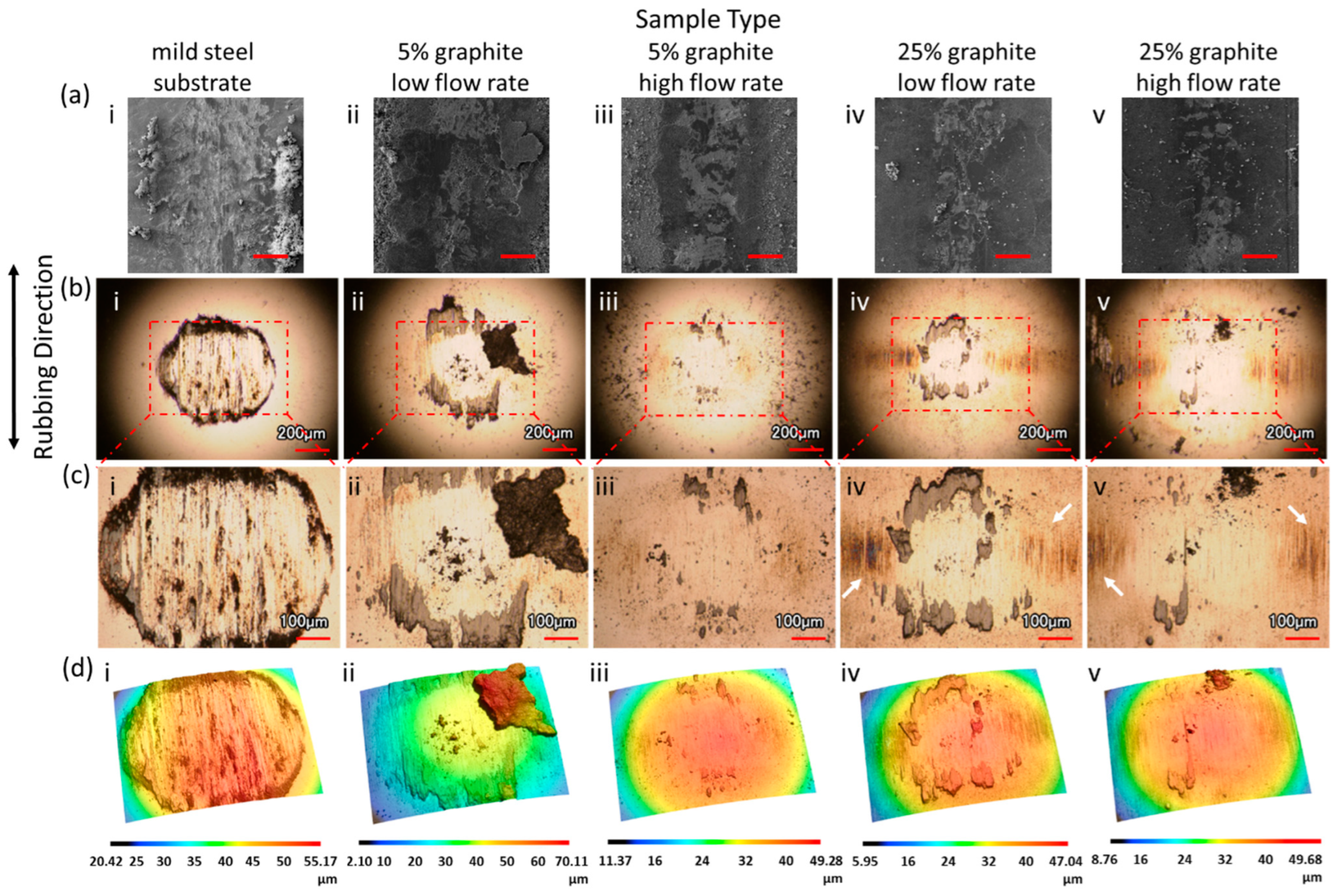
2.4. Wear Analysis
3. Results and Discussion
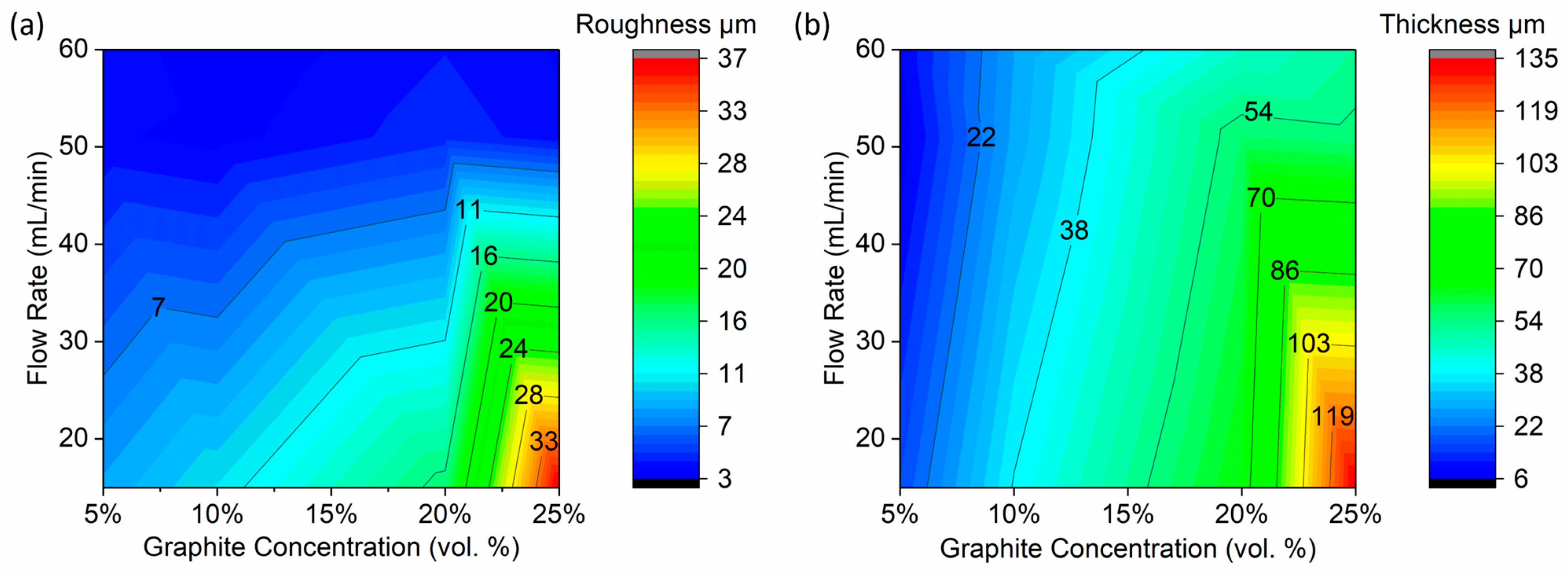
3.1. Coating Morphology, Thickness, and Roughness
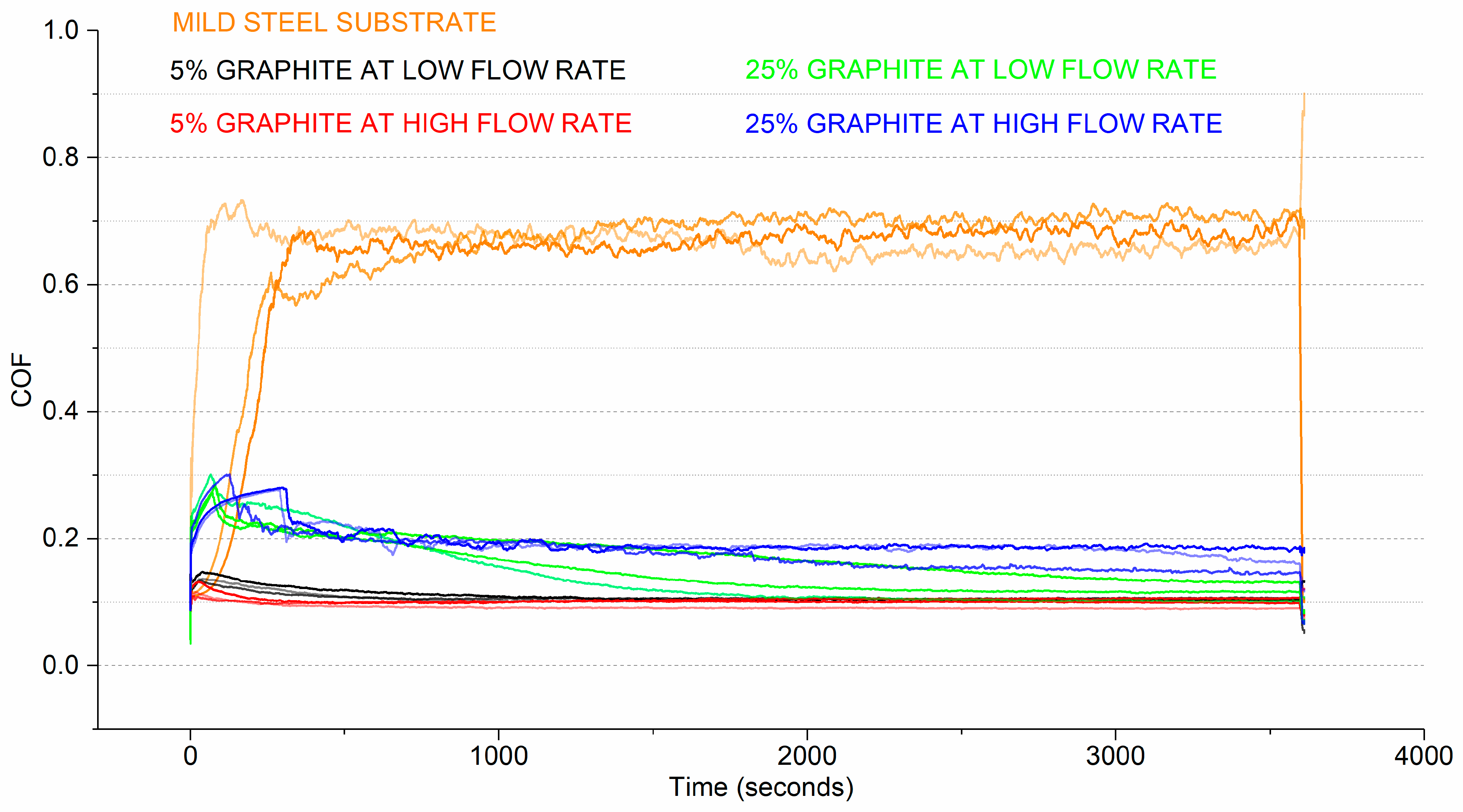
3.2. Friction
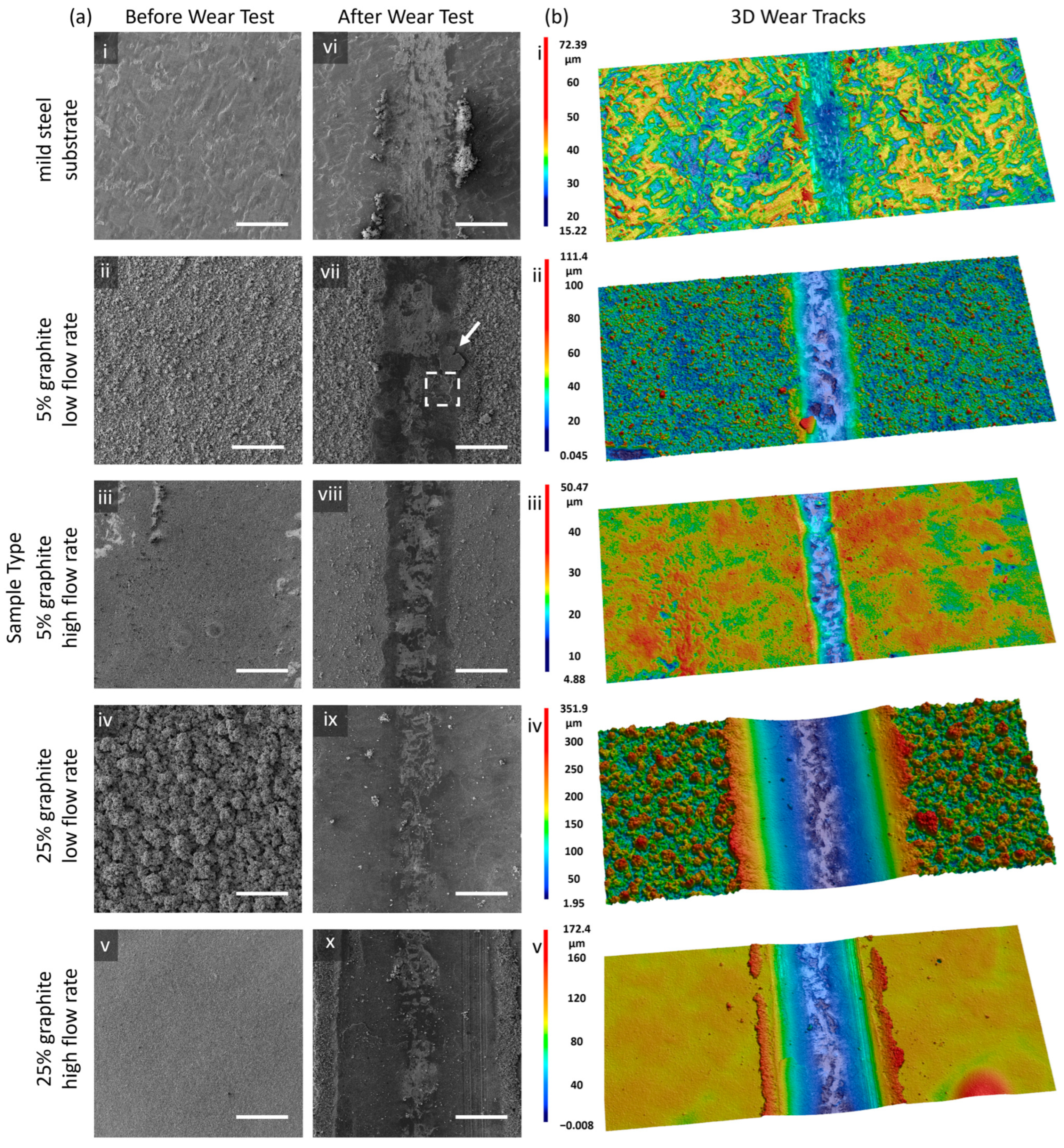
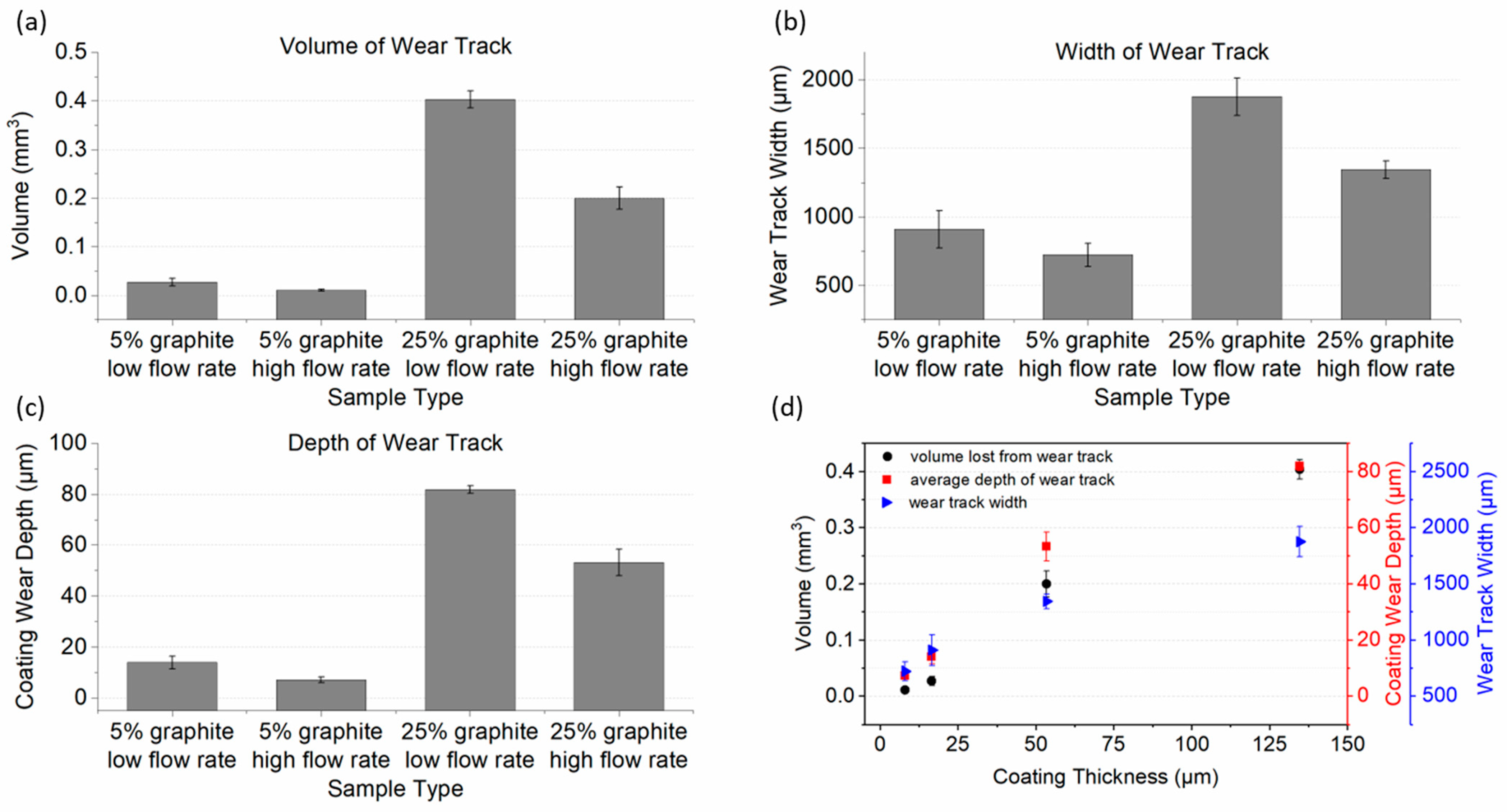
3.3. Wear
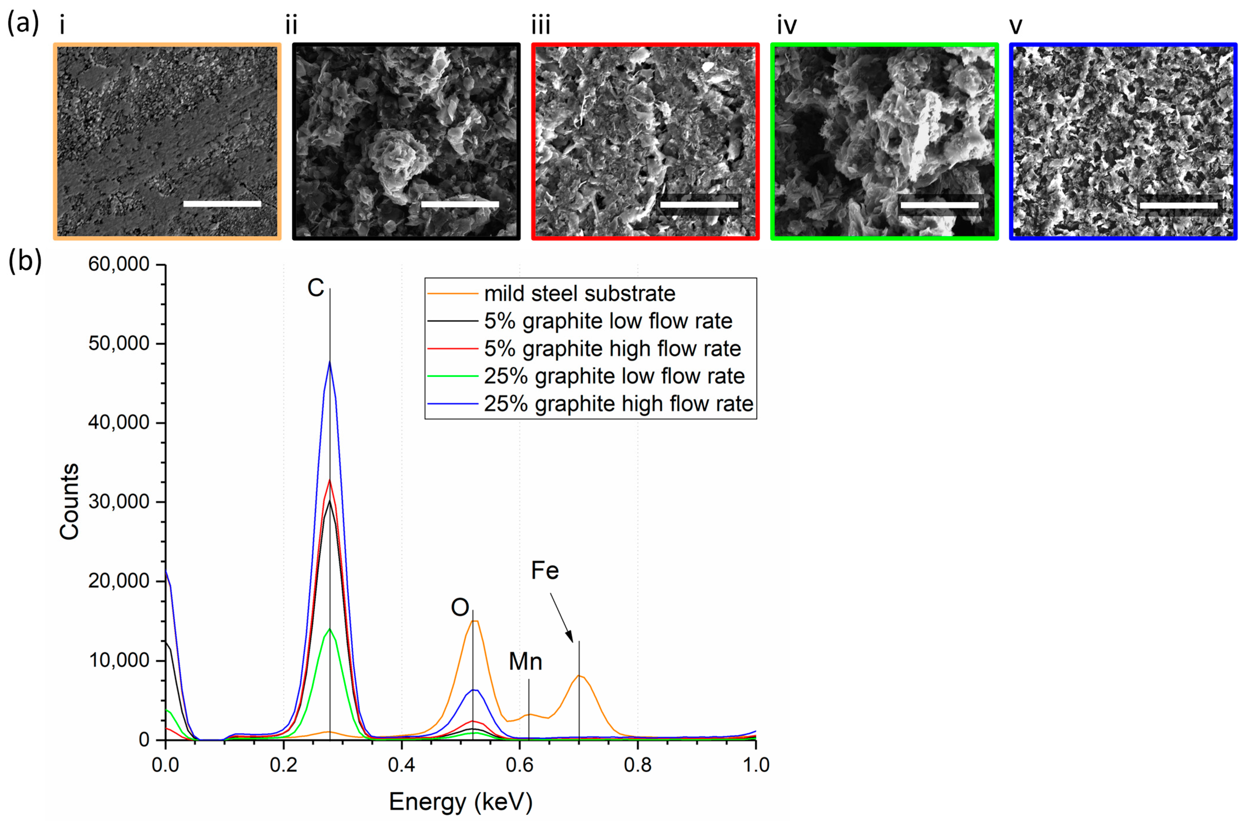
3.4. Elemental Analysis
4. Conclusions
Author Contributions
Funding
Institutional Review Board Statement
Informed Consent Statement
Data Availability Statement
Acknowledgments
Conflicts of Interest
References
- Wang, Z.; Fu, Q.; Wu, S. Effect of solid lubricant particles on the tribological properties of PTFE composites lubricated with natural seawater. J. Dispers. Sci. Technol. 2019, 40, 239–249. [Google Scholar] [CrossRef]
- Ye, S.; Zeng, X. Tribological properties of PTFE and PTFE composites at different temperatures. Tribol. Lubr. Technol. 2014, 70, 32–39. [Google Scholar] [CrossRef]
- Wang, R.; Zhang, F.; Yang, K.; Xiao, N.; Tang, J.; Xiong, Y.; Zhang, G.; Duan, M.; Chen, H. Important contributions of carbon materials in tribology: From lubrication abilities to wear mechanisms. J. Alloys Compd. 2024, 979, 173454. [Google Scholar] [CrossRef]
- Marcinauskas, L.; Mathew, J.S.; Milieška, M.; Aikas, M.; Kalin, M. Effect of graphite concentration on the tribological performance of alumina coatings. J. Alloys Compd. 2020, 827, 154135. [Google Scholar] [CrossRef]
- Ye, W.; Shi, Y.; Zhou, Q.; Xie, M.; Wang, H.; Bou-Saïd, B.; Liu, W. Recent advances in self-lubricating metal matrix nanocomposites reinforced by carbonous materials: A review. Nano Mater. Sci. 2024; in press. [Google Scholar] [CrossRef]
- Ren, Y.; Zhang, L.; Xie, G.; Li, Z.; Chen, H.; Gong, H.; Xu, W.; Guo, D.; Luo, J. A review on tribology of polymer composite coatings. Friction 2021, 9, 429–470. [Google Scholar] [CrossRef]
- Hanada, K.; Hatsukano, K.; Matsuzaki, K.; Umeda, K.; Ishiwata, M.; Tsukita, M. Graphite coating of tool steel by pressure spraying. J. Mater. Process. Technol. 2005, 164–165, 856–861. [Google Scholar] [CrossRef]
- Buzio, R.; Gerbi, A.; Bernini, C.; Repetto, L.; Vanossi, A. Graphite superlubricity enabled by triboinduced nanocontacts. Carbon 2021, 184, 875–890. [Google Scholar] [CrossRef]
- Cao, T.; Lv, Z.; Zhang, W.; Zhang, W. Preparation and tribological behaviours of graphite self-lubricating coating deposited on middle carbon steel by electrospark deposition. Bull. Mater. Sci. 2022, 45, 102. [Google Scholar] [CrossRef]
- Kumar, R.; Hussainova, I.; Rahmani, R.; Antonov, M. Solid Lubrication at High-Temperatures—A Review. Materials 2022, 15, 1695. [Google Scholar] [CrossRef]
- McGrath, M.G.; Vrdoljak, A.; O’Mahony, C.; Oliveira, J.C.; Moore, A.C.; Crean, A.M. Determination of parameters for successful spray coating of silicon microneedle arrays. Int. J. Pharm. 2011, 415, 140–149. [Google Scholar] [CrossRef] [PubMed]
- Almansoori, N.; Aldulaijan, S.; Althani, S.; Hassan, N.M.; Ndiaye, M.; Awad, M. Manual spray painting process optimization using Taguchi robust design. Int. J. Qual. Reliab. Manag. 2021, 38, 46–67. [Google Scholar] [CrossRef]
- Gleeson, D.; Jakobsson, S.; Salman, R.; Ekstedt, F.; Sandgren, N.; Edelvik, F.; Carlson, J.S.; Lennartson, B. Generating Optimized Trajectories for Robotic Spray Painting. IEEE Trans. Autom. Sci. Eng. 2022, 19, 1380–1391. [Google Scholar] [CrossRef]
- Juhász Junger, I.; Großerhode, C.; Storck, J.L.; Kohn, S.; Grethe, T.; Grassmann, C.; Schwarz-Pfeiffer, A.; Grimmelsmann, N.; Meissner, H.; Blachowicz, T.; et al. Influence of graphite-coating methods on the DSSC performance. Optik 2018, 174, 40–45. [Google Scholar] [CrossRef]
- Chen, L.; Duan, Q.; Dong, W.; Zhu, A.; Zhang, A.; Zhang, X.; Zhong, J.; Huang, F.; Cheng, Y.B.; Xiao, J. Sprayed and mechanical-modified graphite layer as transferred electrode for high-efficiency perovskite solar cells. Carbon 2023, 202, 161–166. [Google Scholar] [CrossRef]
- Karas, J.; Pavloková, S.; Hořavová, H.; Gajdziok, J. Optimization of Spray Drying Process Parameters for the Preparation of Inhalable Mannitol-Based Microparticles Using a Box-Behnken Experimental Design. Pharmaceutics 2023, 15, 496. [Google Scholar] [CrossRef] [PubMed]
- Jakkula, R.V.S.K.; Sethuramalingam, P. Analysis of Coatings based on Carbon-based Nanomaterials for Paint Industries-A Review. Aust. J. Mech. Eng. 2023, 21, 1008–1036. [Google Scholar] [CrossRef]
- Barletta, M.; Gisario, A. Electrostatic spray painting of carbon fibre-reinforced epoxy composites. Prog. Org. Coat. 2009, 64, 339–349. [Google Scholar] [CrossRef]
- Ranta, O.; Marian, O.; Muntean, M.V.; Molnar, A.; Ghețe, A.B.; Crișan, V.; Stănilă, S.; Rittner, T. Quality analysis of some spray parameters when performing treatments in vineyards in order to reduce environment pollution. Sustainability 2021, 13, 7780. [Google Scholar] [CrossRef]
- Kim, G.H.; Shin, E.A.; Jung, J.Y.; Lee, J.Y.; Lee, C.K. Effect of Spray Parameters on Electrical Characteristics of Printed Layer by Morphological Study. Processes 2022, 10, 999. [Google Scholar] [CrossRef]
- Poozesh, S.; Akafuah, N.; Saito, K. Effects of automotive paint spray technology on the paint transfer efficiency—A review. Proc. Inst. Mech. Eng. Part D J. Automob. Eng. 2018, 232, 282–301. [Google Scholar] [CrossRef]
- Reitz, R.D.; Bracco, F.B. On the dependence of spray angle and other spray parameters on nozzle design and operating conditions. SAE Tech. Pap. 1979. [Google Scholar] [CrossRef] [PubMed]
- Waldbillig, D.; Kesler, O. The effect of solids and dispersant loadings on the suspension viscosities and deposition rates of suspension plasma sprayed YSZ coatings. Surf. Coat. Technol. 2009, 203, 2098–2101. [Google Scholar] [CrossRef]
- Shi, J.; Cagney, N.; Tatum, J.; Condie, A.; Rafael Castrejon-Pita, J. Jetting and droplet formation of particle-loaded fluids. Phys. Fluids 2024, 36, 017119. [Google Scholar] [CrossRef]
- Morstein, C.E.; Dienwiebel, M. Graphite lubrication mechanisms under high mechanical load. Wear 2021, 477, 203794. [Google Scholar] [CrossRef]
- Ghosh, S.K.; Miller, C.; Choudhury, D.; Goss, J.A.; Zou, M. The Effects of PTFE Thickness on the Tribological Behavior of Thick PDA/PTFE Coatings. Tribol. Trans. 2020, 63, 575–584. [Google Scholar] [CrossRef]
- Miller, C.; Choudhury, D.; Zou, M. The Effects of Surface Roughness on the Durability of Polydopamine/PTFE Solid Lubricant Coatings on NiTiNOL 60. Tribol. Trans. 2019, 62, 919–929. [Google Scholar] [CrossRef]
- Morstein, C.E.; Klemenz, A.; Dienwiebel, M.; Moseler, M. Humidity-dependent lubrication of highly loaded contacts by graphite and a structural transition to turbostratic carbon. Nat. Commun. 2022, 13, 5958. [Google Scholar] [CrossRef]
- Shi, X.; Liskiewicz, T.W.; Beake, B.D.; Chen, J.; Wang, C. Tribological performance of graphite-like carbon films with varied thickness. Tribol. Int. 2020, 149, 105586. [Google Scholar] [CrossRef]
- Vergari, L.; Quincey, J.; Meric de Bellefon, G.; Merriman, T.; Hackett, M.; Scarlat, R.O. Self-lubrication of nuclear graphite in argon at high temperature. Tribol. Int. 2023, 177, 107946. [Google Scholar] [CrossRef]
- Rahman, M.M.; Islam, M.; Roy, R.; Younis, H.; AlNahyan, M.; Younes, H. Carbon Nanomaterial-Based Lubricants: Review of Recent Developments. Lubricants 2022, 10, 281. [Google Scholar] [CrossRef]
- Dienwiebel, M.; Verhoeven, G.S.; Pradeep, N.; Frenken, J.W.M.; Heimberg, J.A.; Zandbergen, H.W. Superlubricity of Graphite. Phys. Rev. Lett. 2004, 92, 126101. [Google Scholar] [CrossRef] [PubMed]


| Full Factorial Design | ||
|---|---|---|
| Run | Flow Rate | Graphite Concentration |
| 1 | low flow rate | 5% |
| 2 | low flow rate | 10% |
| 3 | low flow rate | 20% |
| 4 | low flow rate | 25% |
| 5 | medium flow rate | 5% |
| 6 | medium flow rate | 10% |
| 7 | medium flow rate | 20% |
| 8 | medium flow rate | 25% |
| 9 | high flow rate | 5% |
| 10 | high flow rate | 10% |
| 11 | high flow rate | 20% |
| 12 | high flow rate | 25% |
| Roughness | ||||||
| Source of Variation | SS | df | MS | F | p-Value | F Crit |
| Flow Rate | 1678.75 | 2 | 839.37 | 1352.27 | 2.14 × 10⁻²⁵ | 3.40 |
| Concentration | 513.10 | 3 | 171.03 | 275.54 | 1.01 × 10⁻¹⁸ | 3.01 |
| Interaction | 1023.95 | 6 | 170.66 | 274.94 | 6.70 × 10⁻²¹ | 2.51 |
| Within | 14.90 | 24 | 0.62 | |||
| Total | 3230.69 | 35 | ||||
| Thickness | ||||||
| Source of Variation | SS | df | MS | F | p-Value | F Crit |
| Flow Rate | 6605.27 | 2 | 3302.63 | 61.73 | 3.45 × 10⁻¹⁰ | 3.40 |
| Concentration | 25,505.37 | 3 | 8501.79 | 158.92 | 5.79 × 10⁻¹⁶ | 3.01 |
| Interaction | 7271.27 | 6 | 1211.88 | 22.65 | 8.82 × 10⁻⁹ | 2.51 |
| Within | 1283.95 | 24 | 53.50 | |||
| Total | 40,665.85 | 35 | ||||
Disclaimer/Publisher’s Note: The statements, opinions and data contained in all publications are solely those of the individual author(s) and contributor(s) and not of MDPI and/or the editor(s). MDPI and/or the editor(s) disclaim responsibility for any injury to people or property resulting from any ideas, methods, instructions or products referred to in the content. |
© 2024 by the authors. Licensee MDPI, Basel, Switzerland. This article is an open access article distributed under the terms and conditions of the Creative Commons Attribution (CC BY) license (https://creativecommons.org/licenses/by/4.0/).
Share and Cite
Abe, A.; Goss, J.A.; Zou, M. Exploring the Impact of Spray Process Parameters on Graphite Coatings: Morphology, Thickness, and Tribological Properties. Coatings 2024, 14, 714. https://doi.org/10.3390/coatings14060714
Abe A, Goss JA, Zou M. Exploring the Impact of Spray Process Parameters on Graphite Coatings: Morphology, Thickness, and Tribological Properties. Coatings. 2024; 14(6):714. https://doi.org/10.3390/coatings14060714
Chicago/Turabian StyleAbe, Adedoyin, Josue A. Goss, and Min Zou. 2024. "Exploring the Impact of Spray Process Parameters on Graphite Coatings: Morphology, Thickness, and Tribological Properties" Coatings 14, no. 6: 714. https://doi.org/10.3390/coatings14060714
APA StyleAbe, A., Goss, J. A., & Zou, M. (2024). Exploring the Impact of Spray Process Parameters on Graphite Coatings: Morphology, Thickness, and Tribological Properties. Coatings, 14(6), 714. https://doi.org/10.3390/coatings14060714