Article

Analyzing the Debinding Step of Ti64 Parts Fabricated by 3D Printing Extrusion

by
Ana Silvia González-Pedraza
1,
Didier Bouvard
2,
Jean-Michel Missiaen
2,
Luis Olmos
3,*,
Héctor Javier Vergara-Hernández
1,
Jose Lemus-Ruiz
4 and
Julio César Villalobos
1
1
División de Estudios de Posgrado e Investigación, Tecnológico Nacional de México/I.T. Morelia, Av. Tecnológico #1500, Colonia Lomas de Santiaguito, Morelia C.P. 58120, Michoacán, Mexico
2
CNRS, Grenoble INP, SIMAP, University Grenoble Alpes, 38000 Grenoble, France
3
Universidad Michoacana de San Nicolás de Hidalgo, INICIT, Fco. J. Mujica S/N, Morelia C.P. 58060, Michoacán, Mexico
4
Universidad Michoacana de San Nicolás de Hidalgo, IIMM, Fco. J. Mujica S/N, Morelia C.P. 58060, Michoacán, Mexico
*
Author to whom correspondence should be addressed.
Coatings 2024, 14(6), 715; https://doi.org/10.3390/coatings14060715
Submission received: 17 May 2024 / Revised: 31 May 2024 / Accepted: 31 May 2024 / Published: 5 June 2024
(This article belongs to the Special Issue Recent Advances in Surface Functionalisation)

Abstract

:
The aim of this work is to analyze the effect of the heating rate used during the debinding step on the consolidation of parts fabricated by additive manufacturing using the 3D printing extrusion of Ti64 samples. The cylindrical samples print by extruding MIM pellets of Ti64 mixed with a binder. Dilatometry tests follow the densification of the samples by using three different heating rates during the heating stage. All the samples then undergo the same thermal cycle of sintering. SEM and XRD analyze the microstructure. Microhardness and compression tests evaluate the mechanical properties of the sintered samples. We analyze the corrosion behavior under Hank’s solution. The results indicated that the heating rate used during the debinding step affects the densification by reducing this as the heating rate increases. After sintering, a lower relative density is reached, resulting in decreased mechanical properties and corrosion resistance. The Young’s modulus and yield strength correspond well with those of the Ti64 samples prepared by other techniques with similar porosities. Despite the remaining porosity, the parts fabricated by SLM had worse corrosion behavior than ours. The main conclusion is that the isothermal step during debinding is not necessary to ensure complete binder elimination, which will reduce the process time and thus, the fabrication costs of parts by this technique.

1. Introduction

Currently, the demand for bone implants has greatly increased due to different sicknesses and accidents, as well as long life expectancy. Ti and its alloys, in particular Ti6Al4V (Ti64), are the most commonly used materials for the fabrication of bone implants. Various techniques have been used and/or studied to fabricate such parts [1,2,3]. Among them, additive manufacturing (AM) is the most promising for designing parts close to human bones and reducing costs [4]. In metallic parts, techniques using lasers, such as selective laser melting (SLM), electron beam melting (EBM), and laser powder bed fusion (LPBF), have received much attention, and there are many studies on this topic [5,6,7,8,9]. Although the laser-based technique is a good alternative, it still has some disadvantages for obtaining parts with a bone-like configuration. As a different route, 3D extrusion printing has recently emerged as a new alternative for producing parts by using metal injection molding (MIM) feedstock, which provides slightly more flexibility for controlling the microstructure and properties at the particle scale [10,11,12,13].
Two main ways exist to produce printed parts using the extrusion technique, which depends on the feedstock form used. The first method uses filaments as feedstock [14,15,16,17], and the second method uses pellets [18,19,20]. In both processes, the feedstock is forced to pass through a nozzle to form a thinner filament that follows the impression path programmed to obtain a green part. After that, the part must be consolidated in two steps: binder elimination and sintering. It has been reported for MIM that binder elimination is a key step in obtaining parts without defects [21,22]. The binder elimination of MIM feedstock is carried out in two steps: solvent and thermal debinding. The first is usually made by immersing the parts in water or different solvents at temperatures lower than 80 °C. This process does not show the formation of defects since the binder eliminated is approximately 2 wt.%. However, thermal debinding is more complicated since the quantity of binder eliminated is greater than 10 wt.%, which could lead to the formation of defects, cracks, and the delamination of the parts. Therefore, different works have studied the effect of the thermal cycle used to eliminate the binder, reporting some interesting results [23,24,25,26,27,28]. Hamidi et al. reviewed the different thermal debinding cycles used for parts fabricated by MIM and reported that the heating rate varied from 2 to 10 °C/min with isothermal holding times up to 10 h [23]. Seerane et al. determined the optimal thermal cycle for debinding Ti64 parts fabricated by MIM and concluded that the most important parameter during binder elimination is the heating rate. They found the best results when a 5 °C/min heating rate was used at 450 °C for 1 h [24]. Singh et al. fabricated parts by metal fused filament fabrication (MF3), and they used thermal cycle debinding composed of different steps but with a slow heating rate of 1 °C/min at different temperatures (250 °C, 330 °C, and 440 °C). All the debinding steps were too long at approximately 23 h to ensure the complete elimination of the carbon contained in the binder. After sintering, they obtained parts with 94% relative density and mechanical properties similar to those reported for MIM parts [25]. González-Gutierrez et al. fabricated copper parts by metal extrusion fabrication and evaluated the thermal elimination of the binder at two different temperatures, 250 °C with 1 h of holding time and then heating to 450 °C with 1 h of holding time at a heating rate of 2 K/min. They concluded that this thermal schedule was satisfactory for obtaining the bending properties of complex parts that cannot be obtained by other processing techniques [26]. Singh et al. fabricated parts by 3D-printed extrusion of 17–4 PH steel and copper using a MIM feedstock. They used a heating rate of 1 °C/m up to 500 °C with a dwell time of 1 h to obtain highly dense parts [27,28]. It is understood that having slow thermal cycles can ensure complete binder elimination, avoiding the possibility of defects in the fabricated parts. Nevertheless, it also leads to higher production costs due to its high energy consumption, high-purity gases for disposal, and low mass production over a long period of time, aspects seen from an industrial production point of view that can generate losses. Enneti et al. estimated an expense of 2.5 dollars per kg of part mass for the removal of the binder from small parts using an 8 h cycle [29]. Therefore, the purpose of this work was focused on evaluating such thermal removal in 3D-printed extrusion parts using different heating rates during the debinding step up of to 500 °C with a one-hour dwell time in order to evaluate the effects and interparticle defects that could be formed during binder removal and thus optimize the heating parameters to reduce the cost and production time.

2. Materials and Methods

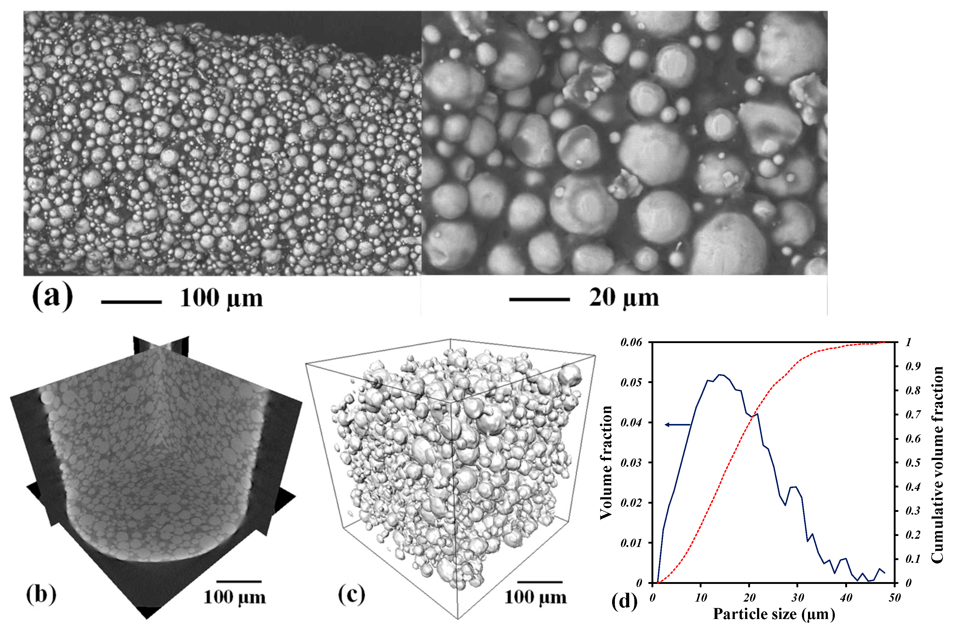
2.1. Materials and 3D Print

The raw material was obtained from PolyMIM (Bad Sobernheim, Germany) and is composed of Ti64 particles with a particle size distribution lower than 45 µm and two polymers, namely polyethylene glycol (PEG) and some wax (not precisely specified by the provider). The cylindrical pellets were approximately 5 mm in diameter and were directly poured into the screw-based extrusion printing machine AIM3D 3D printer (Germany). The samples of 8 mm diameter and 12 mm height were designed in a CAD model by using SolidWorks software (2022 version), and then the model was imported by the Simply 3D program that connects with the 3D printer. The impression parameters used had a layer thickness of 0.05 mm, a nozzle speed of 20 mm/s, an extrusion flow rate of 120% of the standard value, an extrusion temperature of 196 °C, a bed temperature of 60 °C, and an infill density of 100%. These parameters were optimized by Singh et al. [30] for MIM pellets of copper furnished by the same company. For further details on the printing parameters, see [27,28,30].

2.2. Debinding and Sintering

Binder elimination was carried out in two stages. First, the samples were immersed in distilled water at 60 °C for 12 h with magnetic stirring. After that, the samples were dried in a furnace under air at 100 °C for 2 h. Then, the second stage was a thermal process, which was investigated in this work. This process is achieved in a Linseis L75 vertical dilatometer (Germany) under a high rate of flowing argon. The isothermal temperature during debinding was fixed at 500 °C, as reported for works using the same binder [27,28,30]. The heating rate during this stage varied from 2 to 10 °C/min. After this stage, sintering was performed at 1300 °C with a dwell time of 1 h using a heating rate of 20 °C/min. Similar sintering parameters were evaluated by Obasi et al. for Ti64 parts fabricated by the MIM technique, for which densities of 96.4% were obtained [31]. Finally, the samples were cooled inside the dilatometer at 20 °C/min under a flowing argon atmosphere.

2.3. Sample Characterization

The longitudinal sections of the sintered samples were cut, and half of the samples were mounted on conductive Bakelite for surface preparation and handling. The surface was metallographically preprepared by polishing with different SiC papers and alumina powders with a particle size of 1 µm. Finally, the samples were subjected to ultrasonication in a bath for 30 min. The microstructure was observed by scanning electron microscopy (SEM) with a JEOL JSM 7600F field emission scanning electron microscope (FESEM). The crystalline microstructure was determined by X-ray diffraction (XRD) using a D8 Bruker diffractometer. The XRD patterns were acquired with K alpha copper radiation and an energy of 30 kV and 30 mA, with a step size of 0.2 and a time step of 1 s in the 2θ range of 30–90°. The crystallite size is determined by using the free software MAUD.
To analyze the residual porosity of the sintered samples, 3D images were acquired with a Zeiss Xradia 510 Versa nanotomograph. The beam intensity was 120 kV, and 1600 projections were recorded at approximately 360° of the sample with a CCD camera of 1024 × 1024 pixels with a voxel size of approximately 6 µm. The image analysis focused on segmenting the porosity in the whole sample by following manual thresholding to obtain binary images; more details can be found elsewhere [32].

2.4. Mechanical Properties Testing

Microhardness tests were performed with a Mitutoyo MVK-HVL microhardness tester. Twenty indentations were made on the sample’s surface with a load of 50 g/f and a dwell time of 15 s on each sample. The compression tests were carried out in an Instron 1150 universal mechanical testing machine at a strain rate of 0.5 mm.min−1 following ASTM D695-02. The Young’s modulus (E) and the yield stress are calculated from the elastic behavior of the stress-strain curves.

2.5. Corrosion Tests

The corrosion behavior was evaluated using a potentiostat-galvanostat “CorrTest electrochemical Workstation CS350” with a standard three-electrode cell. The samples were evaluated in Hank’s solution, and the evaluation sequence was as follows: an initial open circuit potential (OCP) test for the stabilization of the cell potential for 50 min, followed by electrochemical impedance spectroscopy (EIS) tests in a frequency range of 100,000 Hz to 0.01 Hz, with a perturbation amplitude of 10 mV vs OCP. Finally, potentiodynamic tests were performed in the potential range from −0.5 V to 1.0 Vs OCP, with a sweep rate of 0.5 mV/s.

3. Results

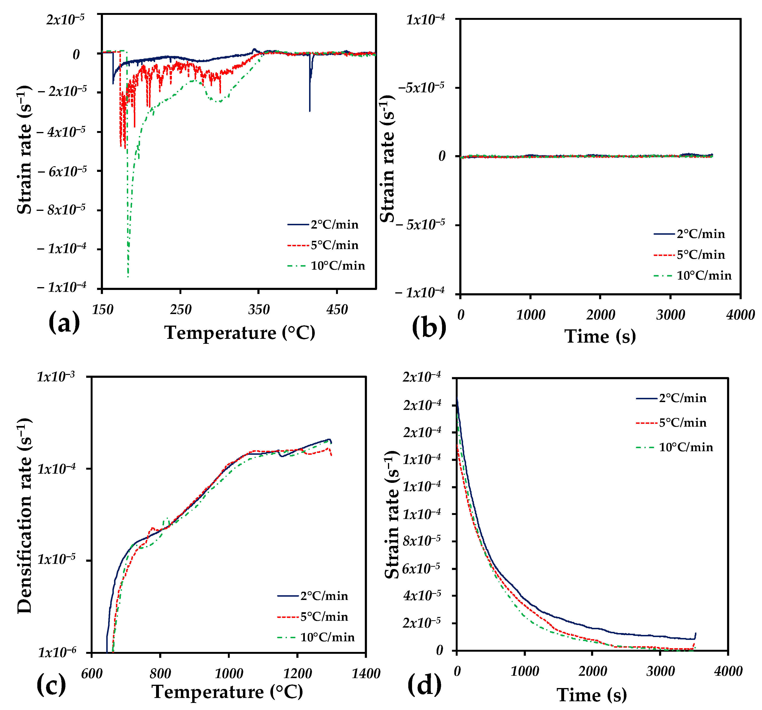
3.1. Debinding and Sintering Analysis

The extruded filament is shown in Figure 1a, in which particles are imbibed in the binder with small isolated pores. To obtain the relative density of the filament, a 3D image was acquired by computed tomography. The voxel resolution of such images was approximately 0.5 µm because the filament diameter was approximately 400 µm. Virtual 2D slices show the distribution of the particles inside the filament (Figure 1b). The binder occupies interparticle spaces with a few isolated pores. To determine the relative density of the solid particles, a virtual cube of 500 × 500 × 500 voxels was cropped from the center of the image, and a thresholding procedure was used to segment the Ti64 particles. The relative density is calculated by counting the number of voxels that correspond to the Ti64 particle divided by the total number of voxels in the cropped cube. A 61.5% relative density was obtained. Figure 1c also shows the distribution of the particles in 3D, and the particle size distribution was obtained by granulometry (Figure 1d) [33]. Most of the particles are smaller than 25 µm, and the median particle size is 15.9 µm.
The axial deformation during debinding and prior to sintering is depicted as a function of the temperature in Figure 2. The heating rate is varied during the debinding stage, but the same heating rate is used for the sintering stage. First, thermal dilation is observed up to 160 °C, at which point negative deformation starts. This is due to binder elimination, which is consistent with the TGA results reported for feedstocks containing similar kinds of binders [28]. The binder elimination ends at approximately 350 °C, depending on the heating rate at which the binder elimination is retarded. After that, the sample did not undergo any dimension changes in the axial direction until sintering was activated at 650 °C; this temperature is consistent with that reported for sintering Ti64 particles [34,35,36]. Once the sintering is activated, a negative deformation is observed until the sintering plateau is reached. Then, during isothermal sintering, linear deformation is observed until cooling starts. At the end of sintering, the samples with the slowest heating rate during the debinding stage exhibited greater shrinkage and negative axial deformation.
With the aim of determining the changes during the whole debinding and sintering stage, the strain rate is depicted as a function of the temperature or time during the isothermal plateaus in Figure 3. The first stage is debinding during heating from room temperature to 500 °C. Figure 3a shows the strain rate as a function of the temperature for the three different heating rates used during this stage. A negative peak is found when binder elimination is activated, which becomes more pronounced as the heating rate increases. In addition, the temperatures at which binder elimination was activated were 163, 173, and 182 °C for samples heated at rates of 2, 5, and 10 °C/min, respectively. After the peak reached the maximum value, a decrease in the strain rate was observed until the value approached 0, indicating that no additional changes occurred in the axial dimension of the samples. The sample heated at 2 °C/min shows a second peak at 415 °C that could correspond to the final elimination of the binder, which is consistent with the TGA results reported elsewhere [28]. On the other hand, samples heated at 5 and 10 °C/min do not show this final peak, which suggests that the binder is eliminated in a short period of time.
Figure 3b shows the strain rate as a function of time during the isothermal plateau at 500 °C, which has been reported to be used for binder elimination in most of the samples fabricated by either MIM or printing 3D by extrusion [23,24,25,26,27,28]. The strain rate remains near 0 for all samples, indicating that no displacement in the axial directions of the samples is detected during the whole plateau. This suggests that all the binder is eliminated during the heating stage, with no visual effect during the isothermal stage of debinding.
Figure 3c shows the strain rate as a function of temperature during the sintering stage. For all the samples, the same heating rate of 20 °C/min was used in this stage. The different samples were named 2, 5, and 10 °C/min as a reference for the heating rate used for the debinding stage. It is observed that sintering is activated between 650 and 660 °C, which is not important since sintering activation has been previously reported from 650 to 700 °C for Ti64 particles depending on the particle size and impurities [34,35,36]. During the sintering stage, the strain rate is barely the same for all samples, which indicates that sintering is well developed during the heating stage. On the other hand, during the sintering plateau, as shown in Figure 3d, the strain rate increases as the heating rate used during the debiding stage decreases. This difference during isothermal sintering increases the final relative density after sintering as the heating rate used during the debinding stage increases to 97, 95, and 92% for samples heated at rates of 2, 5, and 10 °C/min, respectively (Table 1). This could suggest that the rapid elimination of the binder generates a rearrangement of particles with larger interparticle pores that inhibit sintering at the final stage, in which the isolated pores appear and are more difficult to close. This could generate a slow densification during the isothermal stage, which is observed from Figure 3d.

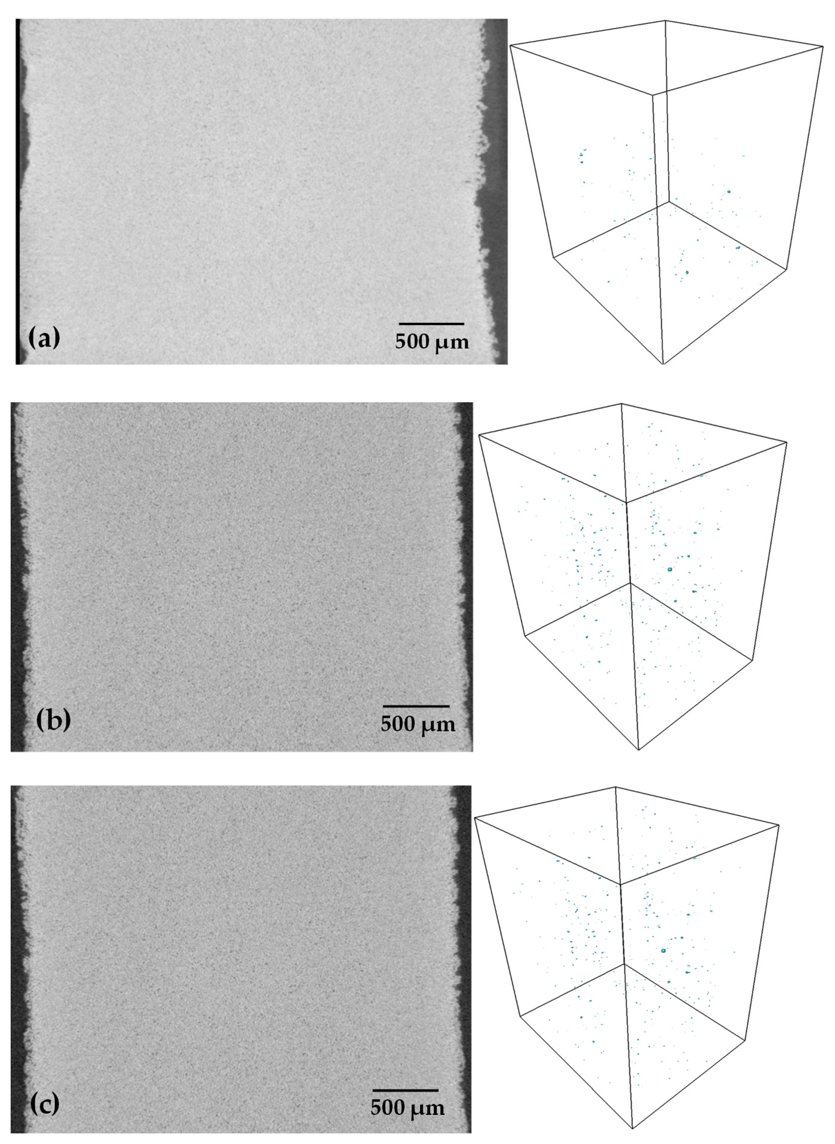
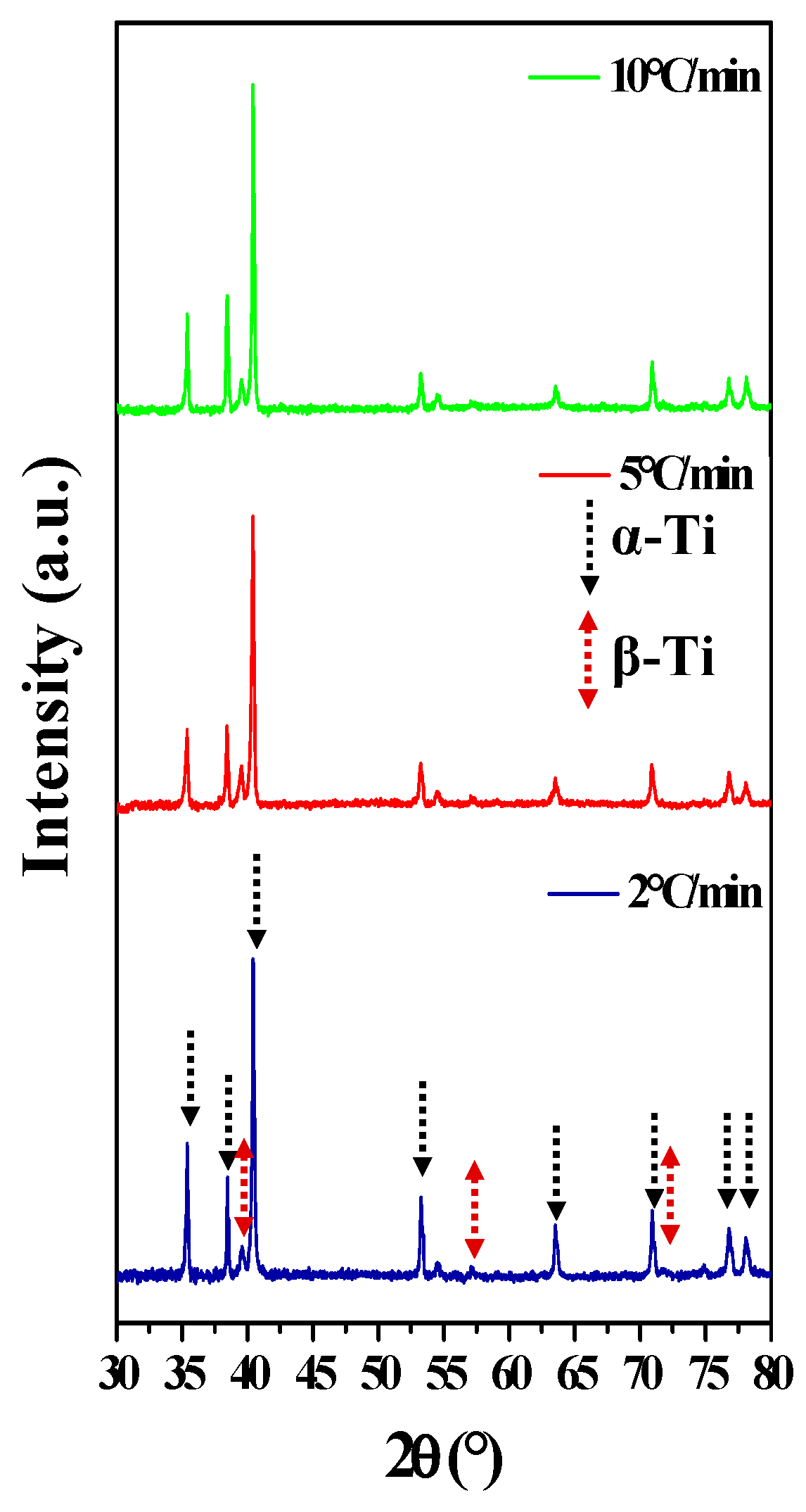
3.2. Sample Characterization

After sintering, 3D images of the whole samples were acquired with a voxel resolution of approximately 6 µm (Figure 4), with the aim of detecting the formation of large pores and/or defects created during the debinding-sintering process. Other works have reported crack formation, fissures, or larger pores formed during the debinding process [29,30]. Virtual 2D slices were extracted from the centers of the samples, in which any defects or large pores were observed regardless of the heating rate used during the debinding step. To determine the porosity, the pores were segmented from 3D images by manual thresholding, and a 3D rendering of the pores is shown for each sample. It was found that the porosity increases as the heating rate increases, particularly when 10 °C/min is used, and a few pores can be found in the center of the sample. Nonetheless, some remaining pores are detected, and their size is less than 20 µm. The printing process was similar for all the samples, which indicates that some larger pores can be formed during the debinding step for higher heating rates. This could confirm that some particle rearrangement occurs during binder elimination when the heating rate is faster, which agrees with the strain rate found by dilatometry. The pore volume fractions measured from the 3D images are 1.7, 3.1, and 4.4% for samples heated at rates of 2, 5, and 10 °C/min, respectively. These porosity values are lower than the real porosity measured because the voxel resolution of 3D images does not allow the detection of pores smaller than 6 µm; however, this analysis focused on defect formation.
Figure 5 shows the microstructure of the samples from a polished surface, where it is possible to observe the small pores and the α + β-Ti lamellar microstructure, which is reported for Ti64 alloys. The circular isolated pores confirmed that the samples are denser than 90%; however, it is not possible to establish a difference in the quantity of the remaining pores. This is mainly because the surface preparation fills some pores during the polishing step. Therefore, to determine whether the heating rate during the debinding step has an influence on the final microstructure, the XRD patterns of each sample are shown in Figure 6. First, the presence of both α + β-Ti phases is confirmed for all the samples. Next, the crystallite size in the α phase was estimated from the XRD patterns by using the Rietveld technique. The obtained values were 1445 ± 72 Å, 1273 ± 51 Å, and 1033 ± 32 Å for the samples heated at rates of 2, 5, and 10 °C/min, respectively. These values can be attributed to the abovementioned disorder generated during the elimination of the binder, and the crystalline structure is affected in the same way; these same results are associated with the densities obtained, as shown in Table 1. It was also assumed from Figure 6 that all the binder was eliminated because the formation of titanium oxides and/or titanium carbides was not detected. Nevertheless, in order to confirm that no carbon is absorbed during additional tests are needed.

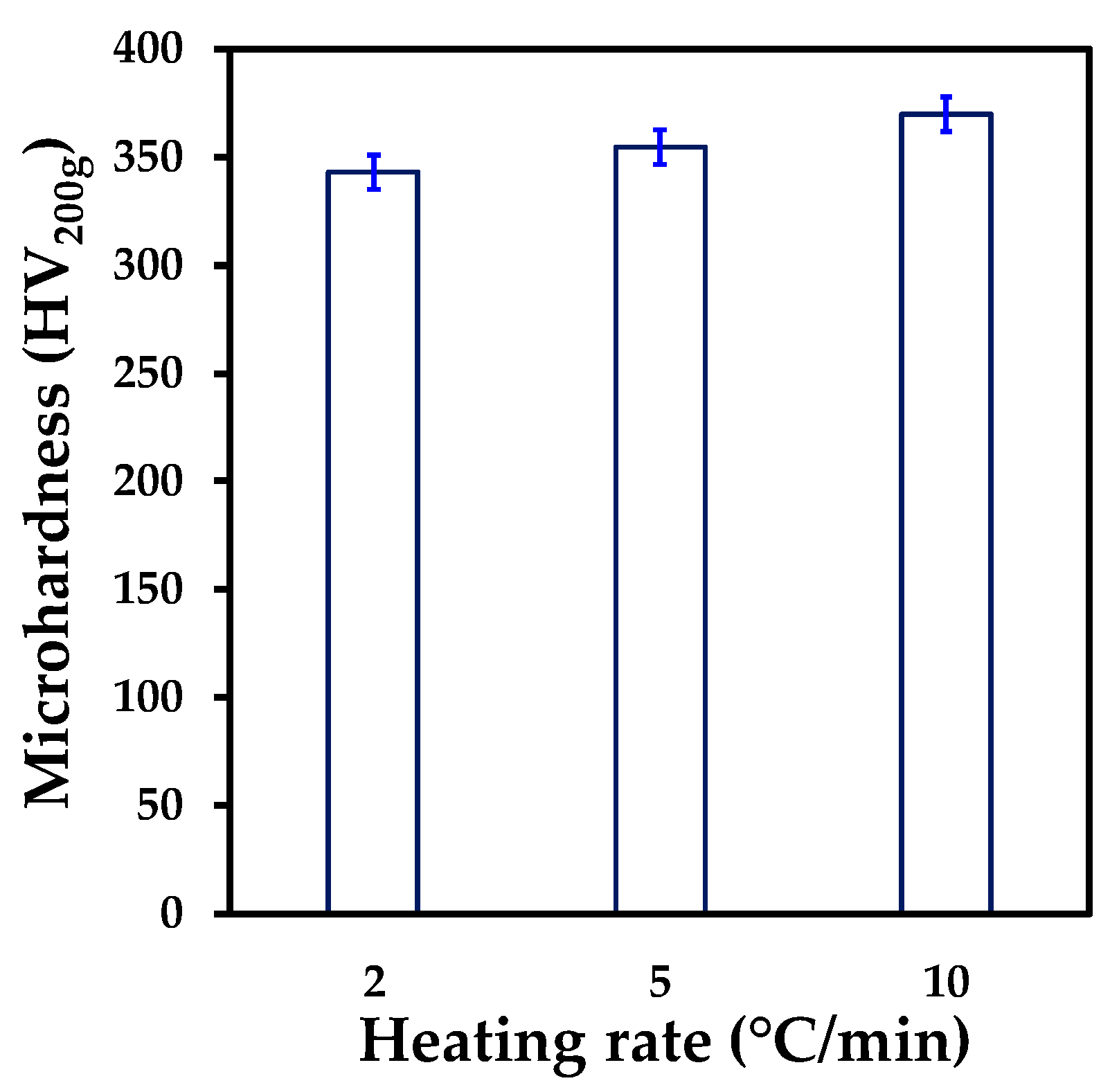
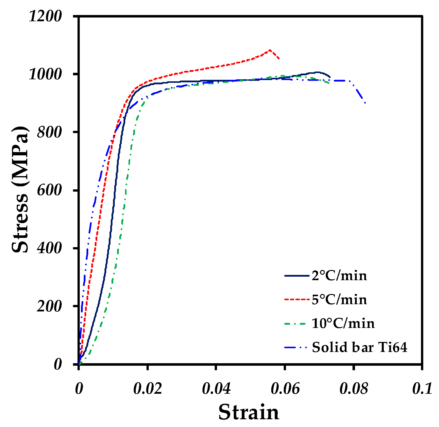
3.3. Mechanical Properties

Since microhardness is a mechanical property that, in turn, depends on the elastic limit of the material, Figure 7 shows that the results plotted are the average of 20 indentations made all over the surface of each sample. The results of the three samples do not reflect a major difference between them. However, the microhardness slightly increased as the heating rate increased. Although the values between the samples are close, the difference could be associated with the crystallite size (grain), as mentioned by Cherkaoui and Capolungo [37]. As the grain size decreases, the mechanical strength increases. The average values of the microhardness are in the range of those reported for samples sintered with similar relative densities and particle size distributions [36].
The stress-strain curves of all the samples after sintering are shown in Figure 8. Similar behavior is found for all the samples, and a curve of the test of a solid bar of Ti64 is added for comparison with the samples fabricated by 3D printing. The Young’s modulus (E) and yield strength (σy) were calculated from the elastic part of the curves and are listed in Table 1 as a function of the heating rate used during the debinding step. The E values decreased as the heating rate increased from 90 to 81.6 GPa. A similar trend is associated with σy 827 to 775 MPa. In comparison, the E and σy of the solid bar were calculated to be 104 GPa and 801 MPa, respectively. The reduction in the E values is associated with an increase in the pore volume remaining after the consolidation of the samples, as was reported in the power law proposed by Gibson and Ashby [38]. Nevertheless, the value of σy shows a small increase with respect to the solid bar, which can be associated with the microstructure that can be refined for sintered materials in comparison to those obtained by casting. The elongation of the samples is similar, although the sample heated at 5 °C/min has the lowest elongation. Compared with the solid bar, the elongation was similar. To compare the results with materials fabricated by similar processes, Ye et al. obtained a value of 800 MPa for σy using a slower heating rate of 3 °C/m [39], while in this study, the same value was obtained but at a rate of 5 °C/m. On the other hand, Singh et al. sintered at 1250 °C and during binder removal at a heating rate of 1 °C/m obtained a σy of 745 MPa with a density of 94.2% [25]. Finally, Zhang et al. used two heating rates within the same ramp, 5 °C/m at 300 °C followed by 2 °C/m at 550°, and, although they evaluated different sintering temperatures, they obtained a higher value of E (155.25 GPa) for the samples sintered at 1340 °C [40].

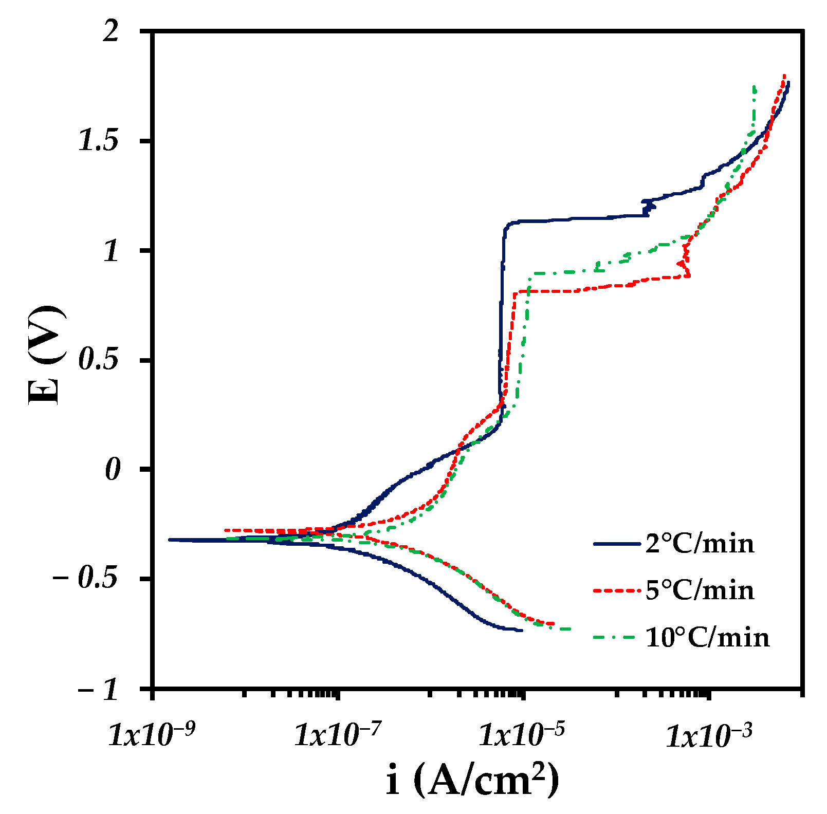
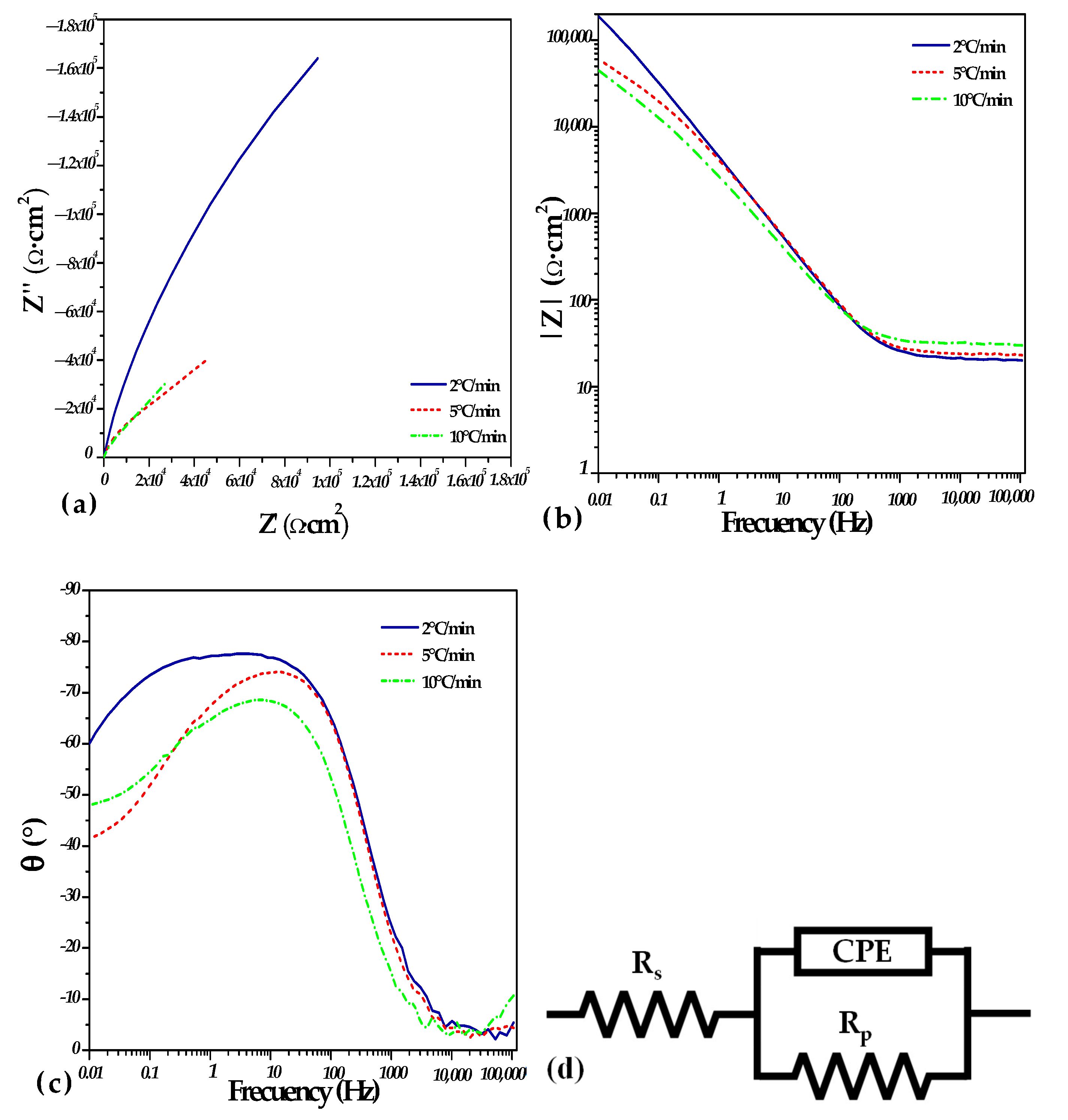
3.4. Corrosion Analysis

Figure 9 shows the polarization curves of the Ti64 samples fabricated with different heating rates during the debinding step. The corrosion potential (E0) does not have a defined tendency; however, the values are close to each other, all having electronegative values ranging from −0.322 V to −0.279 V (see Table 2). This indicates that the susceptibility to corrosion under immersion is similar for the three samples analyzed. These values are better than those reported by Chen et al. [41] for the Ti64 parts fabricated by SLM (−0.548 V) in Hank’s solution. On the other hand, the corrosion rate (Vcorr) shows a clear trend, in which the corrosion rate increases with an increasing heating rate (see Table 2). This phenomenon occurs because at a low heating rate, there is a higher density, which indicates a consolidated system with a smaller electrochemically active area. In contrast, at a higher heating rate, there was a lower density, which generated a greater quantity of isolated pores that could help the solution to sink, increasing the corrosion rate. A greater porosity increases the electrochemically active area, which increases the charge transfer and favors the anodic reaction [42]. It is important to mention that under all heating conditions, a passivation phenomenon was observed at a current density of 1 × 10⁻⁵ A/cm2. The sample with the lowest heating rate shows a better stabilization of the passive layer than the other samples.
In Figure 10a, the Nyquist diagrams are presented, in which the formation of incomplete semicircles can be observed and in which the 2 °C/min condition presents a higher imaginary impedance (Z”) close to 16,000 Ω∙cm2. On the other hand, the 5 °C/min and 10 °C/min conditions presented a much lower imaginary impedance of approximately 4000 Ω∙cm2. Nevertheless, the sample heated at 10 °C/min showed the lowest impedance among all the samples. This is corroborated in the impedance Bode-module diagram, in which the same behavior is presented for the different heating conditions (Figure 10b). Furthermore, the phase Bode-angle diagram (Figure 10c) shows that the 2 °C/min heating condition reaches a maximum peak at approximately −80° at disturbance frequencies of approximately 100 Hz. The 5 °C/min and 10 °C/min conditions also present a maximum peak at this same frequency; however, as the heating rate increases, the magnitude of the phase shift decreases. Due to the heating rate conditions that have been previously analyzed, having a higher density structure presents a higher resistance to corrosion because the impedance is inversely proportional to the capacitance of the electrochemical double layer (2 °C/min condition). In contrast, a less dense structure (higher porosity) contains more active sites for the anodic process, which reduces the impedance and increases the capacitance of the electrochemical double layer. This is associated with a larger electrochemically active area and processes such as lower passivation leading to a higher susceptibility to corrosion (10 °C/min sample).
To quantify the susceptibility to corrosion, the impedance spectra are adjusted at each heating rate by means of an equivalent electrochemical circuit (EEC), as shown in Figure 10d. This circuit consists of a solution resistance (Rs) and two parallel elements consisting of a constant phase element (CPE) and the polarization resistance (Rp). The values related to this adjustment are shown in Table 3. The sample heated at 2 °C/min generated a polarization resistance of 519,180 Ω∙cm2; in contrast, the samples heated at 5 and 10 °C/min showed similar polarization resistances with values close to 70,000 Ω∙cm2. This is again associated with the correlation that the higher the density is, the more the polarization resistance increases remarkably; otherwise, a higher heating rate reduces the polarization resistance, increasing the susceptibility to corrosion. This process was complemented by the polarization curves described above. It is important to note that the CPE-P decreases with an increasing heating rate. This reduction is associated with the constant phase element behaving as a more resistive element rather than a capacitive element because of the porosity and low density of the material.
Cheng et al. [43] and de Assis et al. [44] evaluated the corrosion resistance of Ti64 in Hank’s solution through Bode diagrams, which represented the results obtained from the EIS tests, and they detected capacitive behavior, which indicates the formation of a passive layer in the system. This behavior is obtained at an approximate phase angle of −90°. This is related to the behavior obtained for the 2 °C/min condition. In addition, Tamilselvi et al. [45] observed a higher current density in samples with a higher surface porosity. Such behavior is observed in the results obtained in this work because although the current density increases as the heating speed increases and the heating rate increases, the density slightly decreases, and the porosity of the system increases. Hamza et al. [46] performed a microstructural characterization of the Ti64 parts obtained by SLM and wrought that were subjected to corrosion tests. They determined that the presence of the β phase was responsible for obtaining a higher corrosion resistance, with values close to those obtained in this work.
As discussed above, the heating rate used during the debinding step has an effect on the densification of the samples, which is mainly due to a rearrangement of the particles that make larger interparticle pores, which inhibits densification. As a consequence, the mechanical properties and corrosion resistance decrease as the heating rate during the debinding step increases. On the other hand, the debinding plateau at 500 °C is not necessary to ensure binder elimination since binder elimination is carried out during the heating stage of the samples. Figure 11 shows the axial deformation during debinding and sintering for a sample heated at 5 °C/min with and without a debinding plateau. The axial deformation is barely the same, and the relative density reached is 95%, which suggests that all the properties should be similar.

4. Conclusions

This work analyzed the effect of the heating rate used during the debinding step on the sintering kinetics, densification, and the consequences that led to the microstructure, mechanical, and corrosion properties, which led us to the following conclusions:
The heating rate during the debinding step affects the densification of the samples by a rearrangement of particles that form larger interparticle pores that are difficult to close during sintering. However, no defects were created during the debinding step even for the highest heating rate used.
The isothermal debinding step is not necessary to ensure the complete elimination of the binder; therefore, removal from the thermal cycle is suggested to reduce the process time.
The mechanical properties of the samples are related to the quantity of pores remaining after the consolidations process, which increased as the heating rate increased.
The corrosion behavior shows a similar trend to that of the mechanical properties, but the values obtained are in the range of fully dense Ti64 and better than those reported for SLM fabrication.

Author Contributions

Conceptualization, A.S.G.-P., D.B. and L.O., methodology, A.S.G.-P. and J.C.V.; project administration, J.-M.M. and H.J.V.-H.; supervision, J.-M.M. and D.B.; writing—original draft, formal analysis, L.O., A.S.G.-P. and J.C.V.; investigation, A.S.G.-P., L.O., D.B. and H.J.V.-H.; writing—review and editing, H.J.V.-H. and J.L.-R.; validation, D.B., J.L.-R. and J.-M.M.; image processing, A.S.G.-P. and L.O. All authors have read and agreed to the published version of the manuscript.

Funding

This research was supported by the National Council of Humanities, Science and Technology CONAHCYT via the PhD scholarship of A.S. Gonzaléz-Pedraza, grant number [CVU 1087636], and by the ICTY by project number ICTI-PICIR23-140.

Institutional Review Board Statement

Not applicable.

Informed Consent Statement

Not applicable.

Data Availability Statement

The raw/processed data required to reproduce these findings cannot be shared at this time as the data also forms part of an ongoing study.

Acknowledgments

The authors want to thank the contribution of Dante Arteaga of the LUMIR Geosciences laboratory of UNAM, Juriquilla, to 3D image acquisition and processing.

Conflicts of Interest

The authors declare no conflict of interest.

References

  1. Koju, N.; Niraula, S.; Fotovvati, B. Additively manufactured porous Ti6Al4V for bone implants: A review. Metals 2022, 12, 687. [Google Scholar] [CrossRef]
  2. Rodriguez-Contreras, A.; Punset, M.; Calero, J.A.; Gil, F.J.; Ruperez, E.; Manero, J.M. Powder metallurgy with space holder for porous titanium implants: A review. J. Mater. Sci. Technol. 2021, 76, 129–149. [Google Scholar] [CrossRef]
  3. Alvarado-Hernández, F.; Mihalcea, E.; Jimenez, O.; Macías, R.; Olmos, L.; López-Baltazar, E.A.; Guevara-Martinez, S.; Lemus-Ruiz, J. Design of Ti64/Ta Hybrid Materials by Powder Metallurgy Mimicking Bone Structure. Materials 2023, 16, 4372. [Google Scholar] [CrossRef]
  4. Huang, S.; Wei, H.; Li, D. Additive manufacturing technologies in the oral implant clinic: A review of current applications and progress. Front. Bioeng. Biotechnol. 2023, 11, 1100155. [Google Scholar] [CrossRef]
  5. Song, Y.; Ghafari, Y.; Asefnejad, A.; Toghraie, D. An overview of selective laser sintering 3D printing technology for biomedical and sports device applications: Processes, materials, and applications. Opt. Laser Technol. 2024, 171, 110459. [Google Scholar] [CrossRef]
  6. Stojković, J.R.; Stojković, M.; Turudija, R.; Aranđelović, J.; Marinkovic, D. Adjustable elasticity of anatomically shaped lattice bone scaffold built by electron beam melting Ti6Al4V powder. Metals 2023, 13, 1522. [Google Scholar] [CrossRef]
  7. Zhang, L.C.; Chen, L.Y.; Zhou, S.; Luo, Z. Powder bed fusion manufacturing of beta-type titanium alloys for biomedical implant applications: A review. J. Alloys Compd. 2023, 936, 168099. [Google Scholar] [CrossRef]
  8. Joshua, R.J.N.; Raj, S.A.; Hameed Sultan, M.T.; Łukaszewicz, A.; Józwik, J.; Oksiuta, Z.; Dziedzic, K.; Tofil, A.; Shahar, F.S. Powder Bed Fusion 3D Printing in Precision Manufacturing for Biomedical Applications: A Comprehensive Review. Materials 2024, 17, 769. [Google Scholar] [CrossRef]
  9. Pothala, S.; Raju, M.J. Recent advances of metallic bio-materials in additive manufacturing in biomedical implants—A review. Mater. Today Proc. 2023, in press. [Google Scholar] [CrossRef]
  10. Kolli, S.; Beretta, M.; Selema, A.; Sergeant, P.; Kestens, L.A.; Rombouts, M.; Vleugels, J. Process optimization and characterization of dense pure copper parts produced by paste-based 3D micro-extrusion. Addit. Manuf. 2023, 73, 103670. [Google Scholar] [CrossRef]
  11. Sakib-Uz-Zaman, C.; Khondoker, M.A.H. A Review on Extrusion Additive Manufacturing of Pure Copper. Metals 2023, 13, 859. [Google Scholar] [CrossRef]
  12. Coffigniez, M.; Gremillard, L.; Boulnat, X. Sinter-Based Additive Manufacturing of Graded Porous Titanium Scaffolds by Multi-Inks 3D Extrusion. Adv. Eng. Mater. 2023, 25, 2201159. [Google Scholar] [CrossRef]
  13. Waalkes, L.; Längerich, J.; Imgrund, P.; Emmelmann, C. Piston-based material extrusion of Ti-6Al-4V feedstock for complementary use in metal injection molding. Materials 2022, 15, 351. [Google Scholar] [CrossRef] [PubMed]
  14. Thompson, Y.; Polzer, M.; Gonzalez-Gutierrez, J.; Kasian, O.; Heckl, J.P.; Dalbauer, V.; Kukla, C.; Felfer, P.J. Fused Filament Fabrication-Based Additive Manufacturing of Commercially Pure Titanium. Adv. Eng. Mater. 2021, 23, 2100380. [Google Scholar] [CrossRef]
  15. Singh, P.; Balla, V.K.; Tofangchi, A.; Atre, S.V.; Kate, K.H. Printability studies of Ti-6Al-4V by metal fused filament fabrication (MF3). Int. J. Refract. Met. Hard Mater. 2020, 91, 105249. [Google Scholar] [CrossRef]
  16. Singh, P.; Balla, V.K.; Atre, S.V.; German, R.M.; Kate, K.H. Factors affecting properties of Ti-6Al-4V alloy additive manufactured by metal fused filament fabrication. Powder Technol. 2021, 386, 9–19. [Google Scholar] [CrossRef]
  17. Costa, J.M.; Sequeiros, E.W.; Vieira, M.F. Fused Filament Fabrication for Metallic Materials: A Brief Review. Materials 2023, 16, 7505. [Google Scholar] [CrossRef] [PubMed]
  18. Martin, V.; Gillon, F.; Najjar, D.; Benabou, A.; Witz, J.F.; Hecquet, M.; Quaegebeur, P.; Meersdam, M.; Auzene, D. MIM-like additive manufacturing of Fe3% Si magnetic materials. J. Magn. Magn. Mater. 2022, 564, 170104. [Google Scholar] [CrossRef]
  19. Xu, T.; Long, F.; Liang, Y.; Zhang, H.; Shi, S.; Cheng, Y.; Xu, G.; Li, Z.; Ge, Y. 3D extrusion printing of 304 stainless steel/polypropylene composites and sintering process optimization. Appl. Phys. A 2023, 129, 285. [Google Scholar] [CrossRef]
  20. Ramazani, H.; Kami, A. Metal FDM, a new extrusion-based additive manufacturing technology for manufacturing of metallic parts: A review. Prog. Addit. Manuf. 2022, 7, 609–626. [Google Scholar] [CrossRef]
  21. Bakan, H.I.; Jumadi, Y.; Messer, P.F.; Davies, H.A.; Ellis, B. Study of processing parameters for MIM feedstock based on composite PEG-PMMA binder. Powder Metall. 1998, 41, 289–291. [Google Scholar] [CrossRef]
  22. Páez-Pavón, A.; Jiménez-Morales, A.; Santos, T.G.; Quintino, L.; Torralba, J.M. Influence of thermal debinding on the final properties of Fe–Si soft magnetic alloys for metal injection molding (MIM). J. Magn. Magn. Mater. 2016, 416, 342–347. [Google Scholar] [CrossRef]
  23. Hamidi, M.F.F.A.; Harun, W.S.W.; Samykano, M.; Ghani, S.A.C.; Ghazalli, Z.; Ahmad, F.; Sulong, A.B. A review of biocompatible metal injection moulding process parameters for biomedical applications. Mater. Sci. Eng. C 2017, 78, 1263–1276. [Google Scholar] [CrossRef]
  24. Seerane, M.; Chikwanda, H.K.; Machaka, R. Determination of optimum process for thermal debinding and sintering using Taguchi method. Mater. Sci. Forum 2015, 828–829, 138–144. [Google Scholar] [CrossRef]
  25. Singh, P.; Balla, V.K.; Gokce, A.; Atre, S.V.; Kate, K.H. Additive manufacturing of Ti-6Al-4V alloy by metal fused filament fabrication (MF 3): Producing parts comparable to that of metal injection molding. Prog. Addit. Manuf. 2021, 6, 593–606. [Google Scholar] [CrossRef]
  26. Gonzalez-Gutierrez, J.; Cano, S.; Ecker, J.V.; Kitzmantel, M.; Arbeiter, F.; Kukla, C.; Holzer, C. Bending properties of lightweight copper specimens with different infill patterns produced by material extrusion additive manufacturing, solvent debinding and sintering. Appl. Sci. 2021, 11, 7262. [Google Scholar] [CrossRef]
  27. Singh, G.; Missiaen, J.M.; Bouvard, D.; Chaix, J.M. Copper additive manufacturing using MIM feedstock: Adjustment of printing, debinding, and sintering parameters for processing dense and defectless parts. Int. J. Adv. Manuf. Technol. 2021, 115, 449–462. [Google Scholar] [CrossRef]
  28. Singh, G.; Missiaen, J.M.; Bouvard, D.; Chaix, J.M. Additive manufacturing of 17–4 PH steel using metal injection molding feedstock: Analysis of 3D extrusion printing, debinding and sintering. Addit. Manuf. 2021, 47, 102287. [Google Scholar] [CrossRef]
  29. Enneti, R.K.; Park, S.J.; German, R.M.; Atre, S.V. Thermal debinding process in particulate materials processing. Mater. Manuf. Process. 2012, 27, 103–118. [Google Scholar] [CrossRef]
  30. Singh, G.; Missiaen, J.M.; Bouvard, D.; Chaix, J.M. Copper extrusion 3D printing using metal injection moulding feedstock: Analysis of process parameters for green density and surface roughness optimization. Addit. Manuf. 2021, 38, 101778. [Google Scholar] [CrossRef]
  31. Obasi, G.C.; Ferri, O.M.; Ebel, T.; Bormann, R. Influence of processing parameters on mechanical properties of Ti–6Al–4V alloy fabricated by MIM. Mater. Sci. Eng. A 2010, 527, 3929–3935. [Google Scholar] [CrossRef]
  32. Olmos, L.; Bouvard, D.; Cabezas-Villa, J.L.; Lemus-Ruiz, J.; Jiménez, O.; Arteaga, D. Analysis of compression and permeability behavior of porous Ti6Al4V by computed microtomography. Met. Mater. Int. 2019, 25, 669–682. [Google Scholar] [CrossRef]
  33. Elmoutaouakkil, A.; Salvo, L.; Maire, E.; Peix, G. 2D and 3D Characterization of Metal Foams Using X-ray Tomography. Adv. Eng. Mater. 2002, 4, 803–807. [Google Scholar]
  34. Tischel, F.; Reineke, L.; Alrashdan, J.; Ploshikhin, V. Modelling Sintering Densification of Binder Jetted Ti-6al-4v Samples. Available online: https://papers.ssrn.com/sol3/papers.cfm?abstract_id=4572381 (accessed on 10 May 2024).
  35. Kim, Y.; Lee, J.; Lee, B.; Ryu, H.J.; Hong, S.H. Dilatometric analysis and microstructural investigation of the sintering mechanisms of blended elemental Ti-6Al-4V powders. Metall. Mater. Trans. A 2016, 47, 4616–4624. [Google Scholar] [CrossRef]
  36. Cabezas-Villa, J.L.; Lemus-Ruiz, J.; Bouvard, D.; Jiménez, O.; Vergara-Hernández, H.J.; Olmos, L. Sintering study of Ti6Al4V powders with different particle sizes and their mechanical properties. Int. J. Miner. Metall. Mater. 2018, 25, 1389–1401. [Google Scholar] [CrossRef]
  37. Cherkaoui, M.; Capolungo, L. Atomistic and Continuum Modeling of Nanocrystalline Materials; Springer Series in Materials Science; Springer: New York, NY, USA, 2009; Volume 112, pp. 1–27. [Google Scholar]
  38. Gibson, L.; Ashby, M.F. Cellular Solids: Structure and Properties; Cambridge University Press: Cambridge, UK, 1999. [Google Scholar]
  39. Ye, S.; Mo, W.; Lv, Y.; Wang, Z.; Kwok, C.T.; Yu, P. The technological design of geometrically complex Ti-6Al-4V parts by metal injection molding. Appl. Sci. 2019, 9, 1339. [Google Scholar] [CrossRef]
  40. Zhang, Y.; Bai, S.; Riede, M.; Garratt, E.; Roch, A. A comprehensive study on fused filament fabrication of Ti-6Al-4V structures. Addit. Manuf. 2020, 34, 101256. [Google Scholar] [CrossRef]
  41. Chen, L.Y.; Zhang, H.Y.; Zheng, C.; Yang, H.Y.; Qin, P.; Zhao, C.; Lu, S.; Liang, S.X.; Chai, L.; Zhang, L.C. Corrosion behavior and characteristics of passive films of laser powder bed fusion produced Ti–6Al–4V in dynamic Hank’s solution. Mater. Des. 2021, 208, 109907. [Google Scholar] [CrossRef]
  42. Li, X.; Du, S.; Ma, C.; Shi, T.; Qi, W.; Yang, H. Nano-SiO2 based anti-corrosion superhydrophobic coating on Al alloy with mechanical stability, anti-pollution and self-cleaning properties. Ceram. Int. 2024, 50, 9469–9478. [Google Scholar] [CrossRef]
  43. Cheng, J.; Li, J.; Yu, S.; Du, Z.; Dong, F.; Zhang, J.; Zhang, X. Corrosion behavior of as-cast Ti–10Mo–6Zr–4Sn–3Nb and Ti–6Al–4V in Hank’s solution: A comparison investigation. Metals 2020, 11, 11. [Google Scholar] [CrossRef]
  44. de Assis, S.L.; Wolynec, S.; Costa, I. Corrosion characterization of titanium alloys by electrochemical techniques. Electrochim. Acta 2006, 51, 1815–1819. [Google Scholar] [CrossRef]
  45. Tamilselvi, S.; Raman, V.; Rajendran, N. Evaluation of corrosion behavior of surface modified Ti–6Al–4V ELI alloy in hanks solution. J. Appl. Electrochem. 2010, 40, 285–293. [Google Scholar] [CrossRef]
  46. Hamza, H.M.; Deen, K.M.; Haider, W. Microstructural examination and corrosion behavior of selective laser melted and conventionally manufactured Ti6Al4V for dental applications. Mater. Sci. Eng. C 2020, 113, 110980. [Google Scholar] [CrossRef] [PubMed]
Figure 1. SEM images (a,b) 2D virtual slices in grayscale image, (c) 3D image of the particles inside the extruded filament and (d) particle size distribution. The arrow shows that data in the blue line are in the left of “y” axis.
Coatings 14 00715 g001
Figure 2. Axial strain as a function of temperature during the sintering cycle of the printed samples with different heating rates used during binder elimination.
Coatings 14 00715 g002
Figure 3. (a) Strain rate as a function of temperature during the debinding step, (b) strain rate as a function of time during the 500 °C plateau used for binder elimination, (c) strain rate as a function of temperature up to reach the sintering plateau and (d) strain rate as a function of time during the 1300 °C plateau.
Coatings 14 00715 g003
Figure 4. Virtual 2D slices and 3D rendering of pores in the whole sample after the debinding-sintering process for samples with heating rates of (a) 2, (b) 5, and (c) 10 °C/min during the debinding step.
Coatings 14 00715 g004
Figure 5. SEM images of the samples after sintering with different heating rates during the debinding step. (a,b) 2 °C/min, (c,d) 5 °C/min, and (e,f) 10 °C/min.
Coatings 14 00715 g005
Figure 6. X-ray patterns after the sintering of samples with different heating rates during the debinding step.
Coatings 14 00715 g006
Figure 7. Microhardness as a function of the heating rate during the debonding step.
Coatings 14 00715 g007
Figure 8. Stress–strain compression curves of samples sintered at the same temperature but with different heating rates used during debinding.
Coatings 14 00715 g008
Figure 9. Polarization curves for Hank’s solution of samples sintered at the same temperature but with different heating rates used during debinding.
Coatings 14 00715 g009
Figure 10. (a) Nyquist diagram, (b) Bode impedance module diagram, (c) Bode phase angle diagram, and (d) equivalent electrochemical circuit (EEC).
Coatings 14 00715 g010
Figure 11. Axial strain as a function of temperature during the sintering cycle of the printed samples heated at 5 °C/min during the debinding step with and without an isothermal plateau during binder elimination.
Coatings 14 00715 g011
Table 1. Relative density and mechanical properties of sintered samples with different heating rates during the debinding step.
Heating Rate (°C/min)Relative Density (%)E (GPa)σy (MPa)
297.190.3 ± 2827 ± 13
595.886.1 ± 0.5800 ± 4
1092.181.6 ± 1.3775 ± 12
Table 2. Corrosion parameters obtained from the polarization curves evaluated in Hank’s solution.
Heating RateE0 (V)ba (mV/DEC)bc (mV/DEC)Icorr (A/cm2)Vcorr (mm/year)
2 C/min−0.3224321871.079 × 10−70.0022 ± 1 × 10⁻⁴
5 C/min−0.2792942393.55 × 10−70.0073 ± 3 × 10⁻⁴
10 C/min−0.3125672676.88 × 10−70.0143 ± 7 × 10⁻⁴
Table 3. Equivalent electrochemical circuit parameters obtained from EIS tests.
Heating Rate
(°C/min)
Rs
Ω·cm2
CPE-T F·cm2·Sn−1 × 10⁻⁵CPE-PRp
Ω·cm2
2 °C20.644.62670.86573519,180
5 °C22.545.93580.8144770,926
10 °C29.69.9640.7670670,637
Disclaimer/Publisher’s Note: The statements, opinions and data contained in all publications are solely those of the individual author(s) and contributor(s) and not of MDPI and/or the editor(s). MDPI and/or the editor(s) disclaim responsibility for any injury to people or property resulting from any ideas, methods, instructions or products referred to in the content.

