
Revealing the Microstructure Evolution and Mechanical Properties of Al2O3-Reinforced FCC-CoCrFeMnNi Matrix Composites Fabricated via Gas Atomization and Spark Plasma Sintering


 ,
,
Abstract
1. Introduction
2. Experimental Procedure
2.1. Materials and Processing
2.2. Microstructure and Mechanical Property Characterization
3. Results and Discussion
3.1. Microstructure Characterizations
3.2. Density and Mechanical Property Analyses
4. Conclusions
- (1)
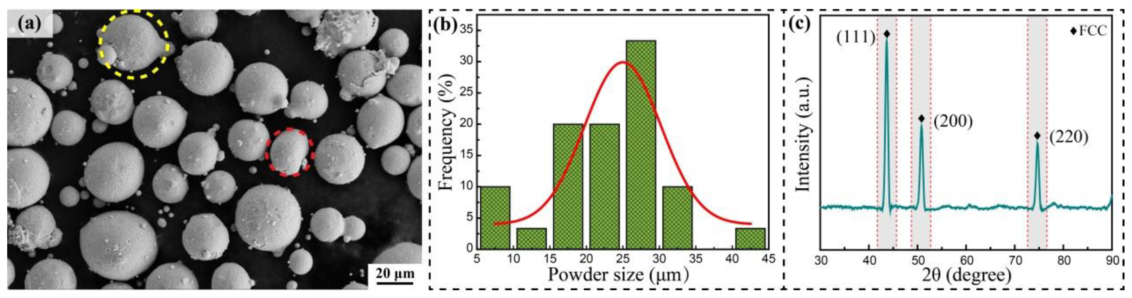
- During the process of high-energy ball milling, the thickness and shape of the powder can be changed by the rapid crushing and welding of the powder. After 12 h of ball milling, the larger-sized HEA powder is elliptical, and the surface is attached to fine Al2O3 particles and the broken-down HEA powder.
- (2)
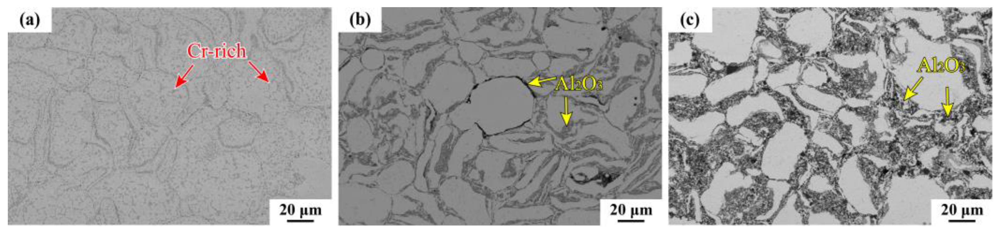
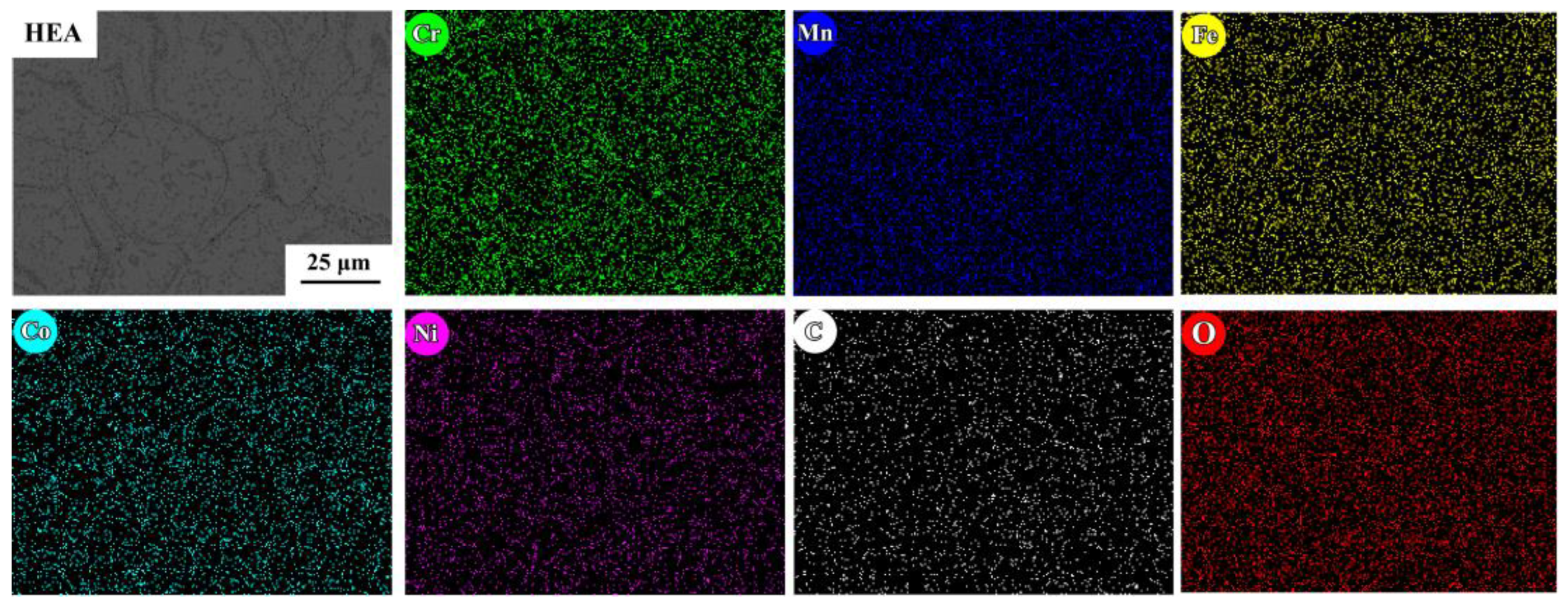
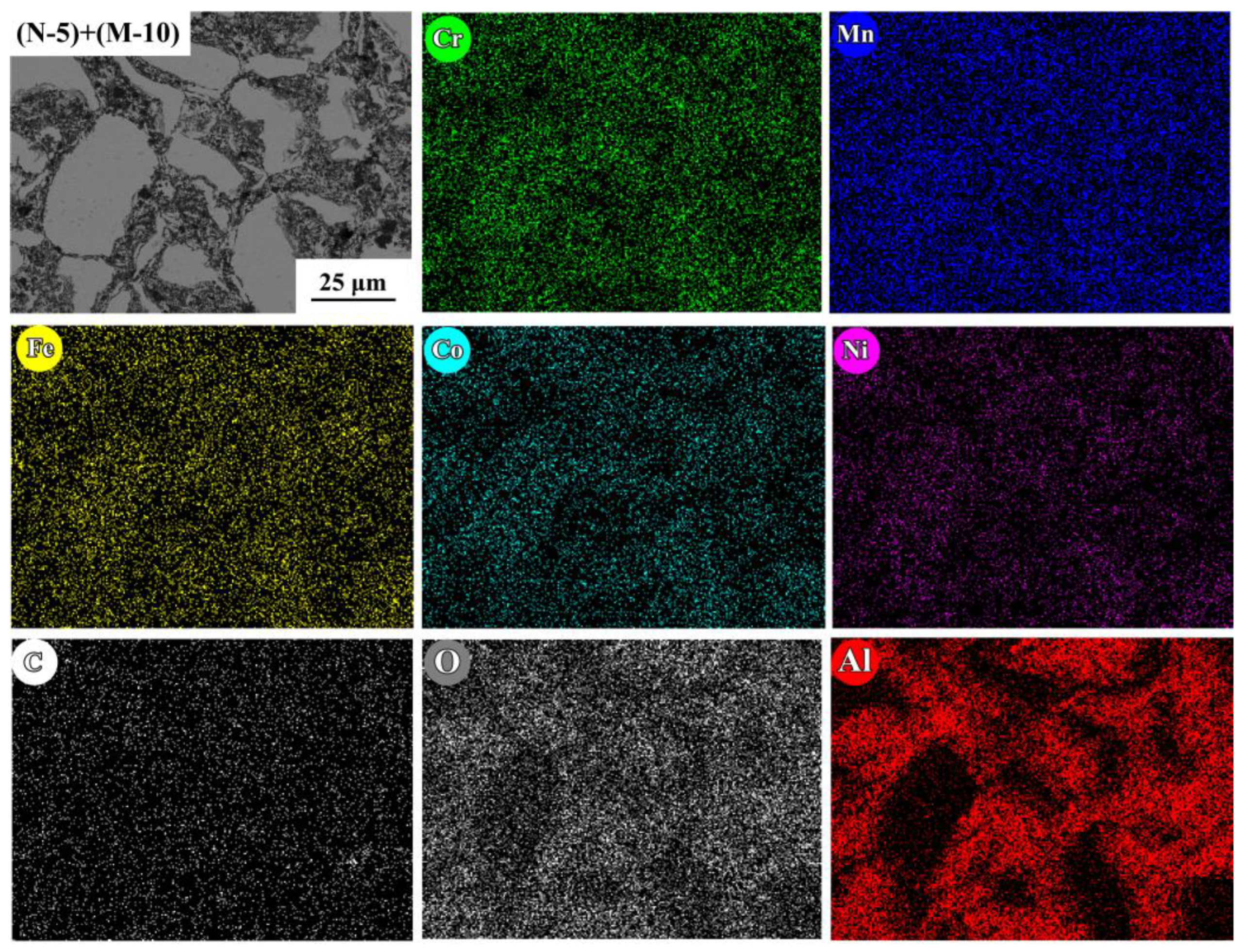
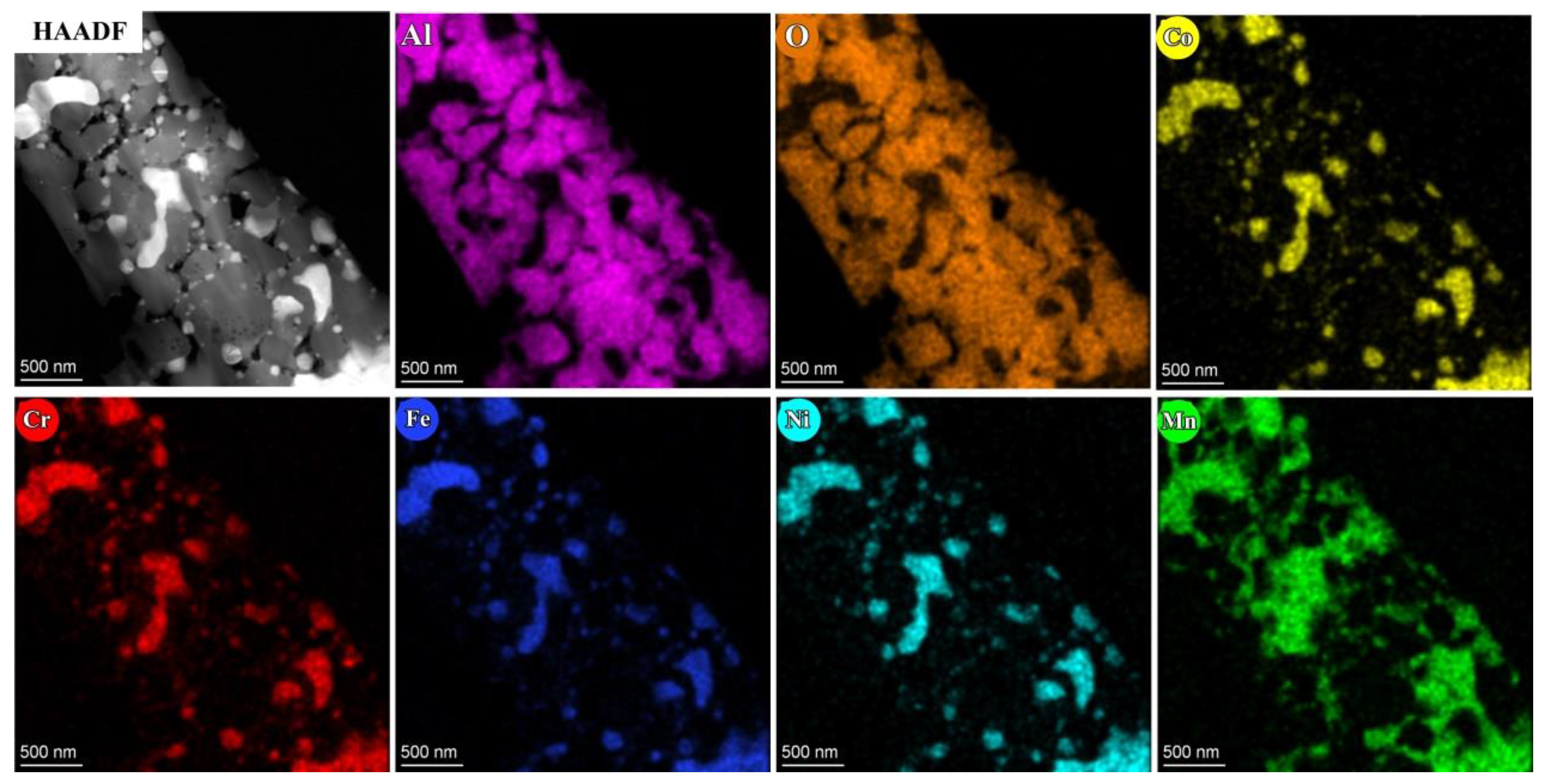
- The dispersion of granular Cr-rich carbides occurs in the pure HEA alloy and is not observed in the composite materials. Compared to the material based on mechanically alloyed HEA powder, the Cr-rich region of the alloy prepared using the GA method is obviously reduced. The actual composition of the five elements in the HEA matrix region is close to the equiatomic ratio, which is consistent with the compositional design. It was proven that using gas-atomized HEA powder as the matrix can effectively reduce powder pollution, inhibit the formation of the impurity phase, and improve composition uniformity.
- (3)
- The composites prepared using gas-atomized powders form a network microstructure composed of continuous Al2O3-rich regions and isolated Al2O3-poor regions, exhibiting improved hardness and yield strength. However, with the addition of hard ceramic Al2O3 reinforcement, the plasticity of the composites becomes worse and the strain-hardening ability becomes weaker; as a result, the compressive rupture strength (ultimate compress strength, i.e., UCS) of the composite is reduced.
Author Contributions
Funding
Institutional Review Board Statement
Informed Consent Statement
Data Availability Statement
Conflicts of Interest
References
- Zhang, L.; Chen, B.; Huang, Y.; Wang, Y.; Liu, W.; Ma, Y. A high strength and high thermally stable nanostructured CoCrFeMnNi alloy prepared by high energy laser shock. Mater. Sci. Eng. A 2023, 885, 145656. [Google Scholar] [CrossRef]
- Zhang, Q.; Wang, Q.; Han, B.; Li, M.; Hu, C.; Wang, J. Comparative studies on microstructure and properties of CoCrFeMnNi high entropy alloy coatings fabricated by high-speed laser cladding and normal laser cladding. J. Alloys Compd. 2023, 947, 169517. [Google Scholar] [CrossRef]
- Ahn, S.; Haftlang, F.; Kim, E.; Jeong, S.; Lee, J.; Kim, H. Boost in mechanical strength of additive manufactured CoCrFeMnNi HEA by reinforcement inclusion of B4C nano-particles. J. Alloys Compd. 2023, 960, 170631. [Google Scholar] [CrossRef]
- Ahn, S.; Haftlang, F.; Kim, E.; Lee, J.; Jeong, S.; Seol, J.; Choi, H.; Kim, H. Cellular structure engineering of additive manufactured CoCrFeMnNi high-entropy composite: The role of hard ceramic reinforcements in elemental segregation of constitutive elements. Addit. Manuf. Lett. 2023, 7, 100172. [Google Scholar] [CrossRef]
- Pegues, J.; Melia, M.; Whetten, S.; Rodriguez, M.; Barrick, E.; Argibay, N.; Kustas, A. Accelerated screening of Tax(CoCrFeMnNi)1−x and Nbx(CoCrFeMnNi)1−x high-entropy alloys. J. Mater. Process. Technol. 2023, 319, 118017. [Google Scholar] [CrossRef]
- Wang, L.; Zanna, S.; Mercier, D.; Maurice, V.; Marcus, P. Early-stage surface oxidation of the equiatomic CoCrFeMnNi high entropy alloy studied in situ by XPS. Corros. Sci. 2023, 220, 111310. [Google Scholar] [CrossRef]
- Dai, P.; Li, A.; Tu, T.; Yang, L.; Luo, X.; Wang, C.; Lv, X. Insight of novel CoCrFeMnNi–Al2O3p high entropy alloy matrix composites by mechanical alloying and spark plasma sintering. J. Mater. Res. Technol. 2023, 26, 4871–4886. [Google Scholar] [CrossRef]
- Xu, Q.; Guan, H.; Huang, S.; Zhong, Z.; Watanabe, H.; Tokitani, M. Compositional stability in medium and high-entropy alloys of CoCrFeMnNi system under ion irradiation. J. Alloys Compd. 2022, 925, 166697. [Google Scholar] [CrossRef]
- Pourghaz, A.; Rajabi, M.; Torabi, M.; Amirnejad, M. The impressive improvement of CoCrFeMnNi high entropy alloy mechanical properties and pitting corrosion resistance by incorporation of carbon nanotube reinforcement. Intermetallics 2023, 163, 108073. [Google Scholar] [CrossRef]
- Chen, H.; Lu, T.; Wang, Y.; Liu, Y.; Shi, T.; Prashanth, K.; Kosiba, K. Laser additive manufacturing of nano-TiC particles reinforced CoCrFeMnNi high-entropy alloy matrix composites with high strength and ductility. Mater. Sci. Eng. A 2022, 833, 142512. [Google Scholar] [CrossRef]
- Veeresham, M.; Jain, R.; Lee, U.; Park, N. Machine learning approach for predicting yield strength of nitrogen-doped CoCrFeMnNi high entropy alloys at selective thermomechanical processing conditions. J. Mater. Res. Technol. 2023, 24, 2621–2628. [Google Scholar] [CrossRef]
- Wang, Y.; Zhao, L.; Wan, D.; Guan, S.; Chan, K. Additive manufacturing of TiB2-containing CoCrFeMnNi high-entropy alloy matrix composites with high density and enhanced mechanical properties. Mater. Sci. Eng. A 2021, 825, 141871. [Google Scholar] [CrossRef]
- Xie, Y.; Luo, Y.; Xia, T.; Zeng, W.; Wang, J.; Liang, J.; Zhou, D.; Zhang, D. Grain growth and strengthening mechanisms of ultrafinegrained CoCrFeNiMn high entropy alloy matrix nanocomposites fabricated by powder metallurgy. J. Alloys Compd. 2020, 819, 152937. [Google Scholar] [CrossRef]
- Chen, Z.; Wen, X.; Wang, W.; Lin, X.; Yang, H.; Jiang, Z.; Chen, L.; Wu, H.; Li, W.; Li, N. Engineering fine grains, dislocations and precipitates for enhancing the strength of TiB2-modified CoCrFeMnNi high-entropy alloy using laser powder bed fusion. J. Mater. Res. Technol. 2023, 26, 1198–1213. [Google Scholar] [CrossRef]
- Yim, D.; Sathiyamoorthi, P.; Hong, S.; Kim, H. Fabrication and mechanical properties of TiC reinforced CoCrFeMnNi high-entropy alloy composite by water atomization and spark plasma sintering. J. Alloys Compd. 2019, 781, 389–396. [Google Scholar] [CrossRef]
- Chena, H.; Kosiba, K.; Lu, T.; Yao, N.; Liu, Y.; Wang, Y.; Prashanth, K.; Suryanarayana, C. Hierarchical microstructures and strengthening mechanisms of nano-TiC reinforced CoCrFeMnNi high-entropy alloy composites prepared by laser powder bed fusion. J. Mater. Sci. Technol. 2023, 136, 245–259. [Google Scholar] [CrossRef]
- Zhang, B.; Yu, Y.; Zhu, S.; Zhang, Z.; Tao, X.; Wang, Z.; Lu, B. Microstructure and wear properties of TiN–Al2O3–Cr2B multiphase ceramics in-situ reinforced CoCrFeMnNi high-entropy alloy coating. Mater. Chem. Phys. 2022, 276, 1253522. [Google Scholar] [CrossRef]
- Zhang, Z.; Zhang, B.; Zhu, S.; Yu, Y.; Wang, Z.; Zhang, X.; Lu, B. Microstructural characteristics and enhanced wear resistance of nanoscale Al2O3/13wt%TiO2-reinforced CoCrFeMnNi high entropy coatings. Surf. Coat. Technol. 2021, 412, 127019. [Google Scholar] [CrossRef]
- Gwalani, B.; Pohan, R.; Waseem, O.; Alam, T.; Hong, S.; Ryu, H.; Banerjee, R. Strengthening of Al0.3CoCrFeMnNi-based ODS high entropy alloys with incremental changes in the concentration of Y2O3. Scripta Mater. 2019, 162, 477–481. [Google Scholar] [CrossRef]
- Zhao, A.; Luo, X.; Ye, Z.; Guo, X.; Huang, B.; Lu, W.; Li, P.; Yang, Y. Microstructure and mechanical properties of novel CrCoNi-Al2O3p medium entropy alloy-matrix composites. Intermetallics 2021, 130, 107057. [Google Scholar]
- Wang, H.M.; Su, W.X.; Liu, J.Q.; Li, G.R.; Liu, Y.; Zhou, P. Microstructure and properties of FeCoNiCrMn and Al2O3 hybrid particle-reinforced aluminum matrix composites fabricated by microwave sintering. J. Mater. Res. Technol. 2023, 24, 8618–8634. [Google Scholar] [CrossRef]
- Rogal, Ł.; Kalita, D.; Litynska-Dobrzynska, L. CoCrFeMnNi high entroy alloy matrix nanocomposite with addition of Al2O3. Intermetallics 2017, 86, 104–109. [Google Scholar] [CrossRef]
- Lehtonen, J.; Ge, Y.; Ciftci, N.; Heczko, O.; Uhlenwinkel, V.; Hannula, S. Phase structures of gas atomized equiatomic CrFeNiMn high entropy alloy powder. J. Alloys Compd. 2020, 827, 154142. [Google Scholar] [CrossRef]
- Kumar, A.; Singh, A.; Suhane, A.; Singh, A.; Verma, P. Artificial age hardening behavior of a squeeze cast CoCrFeMnNi high entropy alloy reinforced 6082-aluminium matrix composite. Mater. Charact. 2023, 206, 113401. [Google Scholar] [CrossRef]
- Litvinov, D.; Lu, K.; Walter, M.; Aktaa, J. Elemental segregation in CoCrFeMnNi high entropy alloy after intermediate-temperature low cycle fatigue loading. Mater. Today Comm. 2023, 35, 106030. [Google Scholar] [CrossRef]
- Nagarjuna, C.; Sharma, A.; Lee, K.; Hong, S.; Ahn, B. Microstructure, mechanical and tribological properties of oxide dispersion strengthened CoCrFeMnNi high-entropy alloys fabricated by powder metallurgy. J. Mater. Res. Technol. 2023, 22, 1708–1722. [Google Scholar] [CrossRef]
- Yang, T.; Cai, B.; Shi, Y.; Wang, M.; Zhang, G. Preparation of nanostructured CoCrFeMnNi high entropy alloy by hot pressing sintering gas atomized powders. Micron 2021, 147, 103082. [Google Scholar] [CrossRef] [PubMed]
- Asghari-Rad, P.; Nguyen, N.; Kim, Y.; Zargaran, A.; Sathiyamoorthi, P.; Kim, H. TiC-reinforced CoCrFeMnNi composite processed by cold-consolidation and subsequent annealing. Mater. Lett. 2021, 303, 130503. [Google Scholar] [CrossRef]
- Kumar, A.; Sharma, S.; Pal, K.; Mula, S. Effect of process parameters on microstructural evolution, mechanical properties and corrosion behavior of friction stir processed Al 7075 alloy. J. Mater. Eng. Perform. 2017, 26, 1122–1134. [Google Scholar] [CrossRef]
- Liu, Y.; Fang, J.; Liu, D.; Lu, Z.; Liu, F.; Chen, S.; Liu, C. Formation of oxides particles in ferritic steel by using gas-atomized powder. J. Nuclear Mater. 2010, 396, 86–93. [Google Scholar] [CrossRef]
- Kunce, I.; Polanski, M.; Karczewski, K.; Plocinski, T.; Kurzydlowski, K. Microstructural characterisation of highentropy alloy AlCoCrFeNi fabricated by laser engineered net shaping. J. Alloys Compd. 2015, 648, 751–758. [Google Scholar] [CrossRef]
- Zheng, K.; Tang, J.; Jia, W.; Wang, Y.; Wang, J.; Shi, Y.; Zhang, G. Microstructure and mechanical properties of Al0.5CoCrFeNi HEA prepared via gas atomization and followed by hot-pressing sintering. J. Mater. Res. Technol. 2024, 30, 5323–5333. [Google Scholar] [CrossRef]
- Luo, X.; Yang, L.; Zhao, A.; Lu, W.; Gan, B.; Yang, Y. Al2O3 nanoparticles reinforced heterogeneous CrCoNi-matrix composites with improved strength-ductility synergy. Mater. Sci. Eng. A 2022, 832, 142398. [Google Scholar] [CrossRef]
- Liu, Y.; Wang, J.; Fang, Q.; Liu, B.; Wu, Y.; Chen, S. Preparation of superfine-grained high entropy alloy by spark plasma sintering gas atomized powder. Intermetallics 2016, 68, 16–22. [Google Scholar] [CrossRef]
- Bhattacharya, A.; Arzt, E. Temperature rise during mechanical alloying. Scripta Metall. Mater. 1992, 27, 749–754. [Google Scholar] [CrossRef]
- Lu, K.; Lu, L.; Suresh, S. Strenthening materials bu engineering coherent internal boundaries at the nanoscale. Science 2009, 17, 349–352. [Google Scholar] [CrossRef]
- Huang, L.; Geng, L.; Peng, H. Microstructurally inhomogeneous composites: Is a homogeneous reinforcement distribution optimal? Prog. Mater. Sci. 2015, 71, 93–168. [Google Scholar] [CrossRef]


| Sample | Chemical Composition (at.%) | ||||
|---|---|---|---|---|---|
| Cr | Co | Fe | Mn | Ni | |
| Pure HEA | 19.04 | 20.28 | 20.89 | 19.16 | 20.63 |
| N-5 | 20.07 | 18.95 | 19.21 | 19.95 | 21.82 |
| (N-5) + (M-10) | 18.68 | 19.73 | 20.79 | 19.34 | 21.45 |
| Specimen | Density (g/cm3) | Relative Density (%) | Hardness (HV0.2) | Compressive Yield Strength(MPa) | Ultimate Compressive Strength (MPa) | Fracture Strain (%) | |
|---|---|---|---|---|---|---|---|
| Theoretical | Actual | ||||||
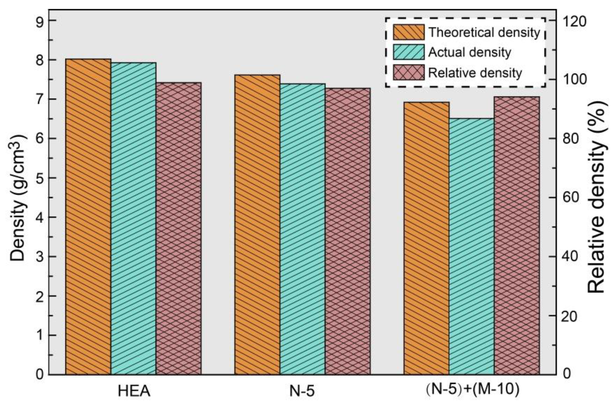
| Pure HEA | 8.016 | 7.925 | 98.9 | 232 | 443 | 1755 | 40 |
| N-5 | 7.614 | 7.387 | 97.0 | 276 | 667 | 1562 | 36 |
| (N-5) + (M-10) | 6.920 | 6.510 | 94.1 | 294 | 706 | 1011 | 15 |
Disclaimer/Publisher’s Note: The statements, opinions and data contained in all publications are solely those of the individual author(s) and contributor(s) and not of MDPI and/or the editor(s). MDPI and/or the editor(s) disclaim responsibility for any injury to people or property resulting from any ideas, methods, instructions or products referred to in the content. |
© 2024 by the authors. Licensee MDPI, Basel, Switzerland. This article is an open access article distributed under the terms and conditions of the Creative Commons Attribution (CC BY) license (https://creativecommons.org/licenses/by/4.0/).
Share and Cite
Dai, P.; Chen, R.; Luo, X.; Yang, L.; Wen, L.; Tu, T.; Wang, C.; Zhao, W.; Lv, X. Revealing the Microstructure Evolution and Mechanical Properties of Al2O3-Reinforced FCC-CoCrFeMnNi Matrix Composites Fabricated via Gas Atomization and Spark Plasma Sintering. Coatings 2024, 14, 737. https://doi.org/10.3390/coatings14060737
Dai P, Chen R, Luo X, Yang L, Wen L, Tu T, Wang C, Zhao W, Lv X. Revealing the Microstructure Evolution and Mechanical Properties of Al2O3-Reinforced FCC-CoCrFeMnNi Matrix Composites Fabricated via Gas Atomization and Spark Plasma Sintering. Coatings. 2024; 14(6):737. https://doi.org/10.3390/coatings14060737
Chicago/Turabian StyleDai, Pan, Runjie Chen, Xian Luo, Lin Yang, Lei Wen, Tao Tu, Chen Wang, Wenwen Zhao, and Xianghong Lv. 2024. "Revealing the Microstructure Evolution and Mechanical Properties of Al2O3-Reinforced FCC-CoCrFeMnNi Matrix Composites Fabricated via Gas Atomization and Spark Plasma Sintering" Coatings 14, no. 6: 737. https://doi.org/10.3390/coatings14060737
APA StyleDai, P., Chen, R., Luo, X., Yang, L., Wen, L., Tu, T., Wang, C., Zhao, W., & Lv, X. (2024). Revealing the Microstructure Evolution and Mechanical Properties of Al2O3-Reinforced FCC-CoCrFeMnNi Matrix Composites Fabricated via Gas Atomization and Spark Plasma Sintering. Coatings, 14(6), 737. https://doi.org/10.3390/coatings14060737