Abstract
This study evaluates the effectiveness of a silica preceramic polymer for joining and coating Plasma Electrolytic Oxidated (PEO) aluminum components at temperatures below 200 °C. PEO aluminum slabs were coated and joined with a silica precursor polymer (Durazane1800, Merck, Darmstadt, Germany), both with and without the addition of 48 wt% silica nanoparticles, and cured at 180 °C for 4 h in air. Thermogravimetric analysis assessed the curing process and thermal stability, while X-ray diffraction confirmed the polymer’s conversion to amorphous silica after heating at 1200 °C. Resistance to humid environments was tested by soaking coated samples in tap water for a week, with no mass variation observed. Mechanical testing through tensile mode and tensile lap tests showed that adding 48 wt% silica nanoparticles significantly improved joint cohesion and nearly quadrupled mechanical strength. Fracture surfaces were examined using Field Emission Scanning Electron Microscopy, and composition analysis was performed with Energy Dispersion X-ray Spectroscopy. Crack detection was conducted using Computer Tomography with an in situ bending test setup to obtain the mechanical resistance of the PEO coating. The results indicate that the silica preceramic polymer is suitable for joining and coating PEO aluminum components, with silica nanoparticles enhancing mechanical strength and providing excellent thermal stability and resistance to humidity.
1. Introduction
Plasma Electrolytic Oxidation (PEO) of aluminum components has garnered significant interest for a variety of applications, ranging from substituting steel to enhancing electronic devices. Numerous studies in the literature have focused on optimizing the Plasma Electrolytic Oxidation process on aluminum substrates, primarily due to the advantageous combination of aluminum’s low density and the high hardness of the alumina coating [1,2]. This combination is particularly beneficial for components that require rapid movement and are subject to wear.
Reducing the mass of moving parts results in increased movement speed, lower energy consumption, and diminished friction losses. Applications of PEO aluminum components include wear-resistant coatings for textiles, packaging, automotive parts, and molds, as well as abrasion-resistant coatings for turbocharger wheels. They are also used for corrosion-resistant coatings in transportation sectors such as automotive, marine, and aerospace industries; engine components; plasma erosion-resistant coatings for microplasma generator components; and decorative coatings.
In certain applications, the aforementioned PEO aluminum components require appropriate joining and coating processes that must be performed at temperatures below 200 °C. This precaution is necessary to prevent distortion or delamination of the surface layer, which can occur due to the mismatch in the thermal expansion coefficients between the metal substrate and the oxide layer.
Silica is well known for its high-temperature resistance, mechanical strength, and resistance to corrosion and wear, making it an excellent choice as a coating and joining material. Silica, particularly in its glass form, is frequently used for sealing and joining components. The typical procedure involves heating the glass above its softening temperature to reduce its viscosity sufficiently, enabling its use as a high-temperature adhesive. However, the temperatures required to soften silica are unsuitable for most metals, especially aluminum-based alloys.
Several alternatives exist for obtaining silica coatings at lower temperatures, such as chemical and vapor deposition or sol-gel techniques [3,4,5,6,7,8]. While both chemical and vapor deposition techniques necessitate expensive facilities, the sol-gel method offers a cost-effective alternative. However, the processing time required to achieve high-quality coatings through sol-gel can be extensive.
For low-temperature joining materials and technologies applicable to aluminum-based components, organic adhesives emerge as promising candidates [9,10,11]. Despite their advantages, these adhesives exhibit limited temperature resistance and thermal expansion properties that are often unsuitable for applications requiring thermal stability. Additionally, adhesives are sensitive to humidity [12,13], which can adversely affect the overall durability and lifespan of the components.
Silica preceramic polymers present an intriguing alternative as coating and joining materials for PEO (Plasma Electrolytic Oxidation) aluminum components. Their processing time is significantly shorter than that required for the sol-gel process, and the technology is less expensive than chemical and vapor deposition methods. Most importantly, these polymers can be converted to silica at temperatures below 900 °C.
Preceramic polymers offer considerable flexibility: despite having a basic structure composed of light elements such as C, H, O, N, and B, their structure can be modified to achieve desired properties, such as enhanced mechanical and thermal characteristics, or the introduction of new ones. Additionally, temperatures and process times (cross-linking and pyrolysis) can be easily optimized. They can be produced with significant energy and cost savings and superior properties compared to conventional ceramics [14,15].
Nonetheless, challenges must be addressed during polymer-to-ceramic conversion, including shrinkage, residual porosity, and related defects, which can significantly reduce the mechanical strength and elastic modulus of the resulting materials. One potential solution is the incorporation of active or passive fillers and the careful optimization of heat treatment protocols to minimize shrinkage [16,17,18,19].
“While the literature on silica preceramic polymers is abundant dating back to the beginning of the last century [15,20,21] the use of these materials as joining and coating materials for Plasma Electrolytic Oxidated (PEO) aluminum components has been not investigated yet, while multiple research works on other methodologies to join PEO materials have been already published [22,23,24,25]”.
The aim of the present work is to study the suitability of a silica preceramic polymer for joining and coating PEO aluminum components at temperatures below 200 °C, focusing on the mechanical strength and environment resistance with or without the addition of silica nanoparticles.
2. Materials and Methods
Plasma Electrolytic Oxidated (PEO) aluminum (Al in the text) slabs have been provided by Cambridge Nanolitic, Cambridge, UK, consisting of Al (20–70 µm coated) measured using eddy currents, as reported in [26], and thick alpha and gamma nano alumina (crystallite size 30–80 nm) obtained via proprietary soft sparking PEO technology. The average grain size was derived using X-ray diffraction measurements, as reported in [26,27]. The treatment was conducted in a phosphate–silicate electrolyte maintained at room temperature of 25 °C with the use of bipolar electrical pulses with 700 V amplitude and repetition frequency of 2 KHz.
The selected polymer was a silica precursor polymer (Durazane1800, Merck, polymer in the text [28]), cured at 180 °C for 4 h, in air, according to the available data sheet. It is a liquid, low-viscous, solvent-free polysilazane resin, which looks like a colorless liquid. Its density is 0.950–1.050 g/cm3 at 25 °C and its viscosity 10–40 cP at 20 °C [1]. It is characterized by good adhesion, hardness, hydrophobicity, and barrier properties and it is applicable to metal, glass, and ceramic substrates. For these reasons, Durazane 1800 is suitable for industrial applications as a high-temperature coating in order to protect metals from corrosion [29,30,31]. The polymer consists of a silicon and nitrogen backbone functionalized with different side groups, usually hydrogen, methyl (CH3), and vinyl (CH=CH2) groups, which contribute to crosslinking via vinyl polymerization [32,33]. Typically, curing is performed using radical initiators, to allow a reduction in curing temperature or time, but catalysts can be avoided, as it in this study, when curing is performed at 180 °C, 4 h, in air, according to the polymer’s data sheet.
In order to verify the thermal stability of the cured polymer, thermogravimetric analyses (TGA) were performed using NETZSCH STA 2500 Regulus apparatus (Selb, Germany) equipped with a tailor-made, ultra-micro balance with a resolution of 0.03 μg. The analysis was performed on the cured polymer in air flow (40 mL/min) with 10 °C/min heating rate, up to 1200 °C, followed by free cooling.
X-ray diffraction (XRD) analysis was performed on the polymer treated at 1200 °C, using an X’Pert Pro MRD diffractometer, with Cu Kα radiation (PANalytical X’Pert Pro, Philips, Almelo, The Netherlands), and with the aid of X-Pert HighScore software v.5.1 (JCPDS database provided by PDF-4 ICDD, International Centre for Diffraction Data, Newton Square, PA, USA).
PEO aluminum samples of 15 mm × 15 mm were cut (Brillant 220 cutting machine, QATM, Mammelzen, Germany) from a larger slab and cleaned in an ultrasonic bath (Proclean 4.5S, Ulsonix, Berlin, Germany) in ethanol (20 min, 40 °C), before being coated by the polymer through a manual process. The polymer was also sandwiched between two samples (PEO side) to obtain a joint of about 20 µm, with a pressure of about 5 kPa applied to keep the sample in position during the process; all coated and joined samples were then cured at 180 °C for 4 h in a furnace operating in air (Binder ED 23, Tuttlingen, Germany), according to the polymer datasheet.
The resistance of the coated samples in the humid environment was preliminary assessed by soaking them for 1 week in tap water at room temperature and measuring their weight variation using an analytical balance (AR2140, OHAUS Europe GmbH, Nänikon, Switzerland) with a resolution of 0.1 mg.
Joined samples were glued to steel cylinders using a two-component epoxy adhesive (DP490) and tested in tensile mode at room temperature according to a modified ASTM C633-01 [34] (on four samples) using a MTS Criterion model 43 machine (MTS Systems Corporation, Eden Prairie, MN, USA) equipped with a 5 kN load cell. The configuration used for the tensile test is reported in [35,36]. The cross-head speed was set to 0.5 mm/min to cause fracturing under quasi-static conditions. The strength (ultimate tensile stress, UTS) was calculated as
where F is the peak load and A is the joined area.
σ = F/A
The cross sections of the joined samples and fracture surfaces after mechanical tests were observed using FESEM and their composition was analyzed using EDS (JEOL JCM-6000 PLUS, Tokyo, Japan, equipped with an Energy Dispersive X-ray Spectroscopy (EDS) analyzer and FESEM-ZEISS Supra 40, Oberkochen, Germany, with EDS-SW9100 EDAX detector, Pleasanton, CA, USA).
Silica nanoparticles of up to 48 wt% (80 nm average diameter, Alfa Aesar, Haverhill, MA, USA) were added to the polymer via manually stirring at room temperature, using a metal rod in a graduated Eppendorf tube. The resulting material was highly viscous and was cured at 180 °C for 4 h in air to obtain coatings and joints as described before. Its thermal stability was tested via TGA up to 1200 °C.
Also, single-lap mechanical tests on joined samples were performed according to ASTM D1002-10 [37], in triplicate.
Computer Tomography inspection with in situ bending test (IKTS-Fraunhofer Institute, Dresden, Germany) was performed to measure the maximum resistance of the coating under bending stress. Four different tomography reconstructions were performed, the first one with no bending load and the other three with 95 N, 115 N, and 165 N bending loads applied, respectively. The tomography parameters used were 150 kV and 50 µA, with 1600 projections for each loading conditions. The reconstructed 3D volumes of the investigated specimen were obtained by using the filtered back projection algorithm through VG MAX 3.5 software (Volume Graphics GMbH, Heidelberg, Germany).
In order to calculate the stress on the coating during the bending test carried out within the CT, similar tests were carried out using a Zwick Roell Z050 machine equipped with 5 kN load cell. Specimen of 5.2 mm × 1.5 mm cross section were subjected to 4-point bending test with a load span equal to 27.5 mm and a support span equal to 67.5 mm, i.e., at the same conditions used during the in situ flexural test within the CT. The stress at which the cracks appeared in the tomography can be calculated as
where:
σ(fmax) = (M(t/2))/I
- σ(fmax) is the maximum flexural stress in the bar, occurring in the outer surface of the bar;
- M is the bending moment developed between the loading pins;
- t is the thickness of the bar;
- I is the moment of inertia of the bar.
In order to detect the presence of cracks at different flexural loading conditions, FESEM inspection were carried out on each sample (Tescan MIRA3, Brno, Czech Republic).
3. Results and Discussion
Figure 1 shows an optical and three FESEM micrographs at higher magnifications of the aluminum slabs where the nanocrystalline structure of the PEO coating is clearly visible.
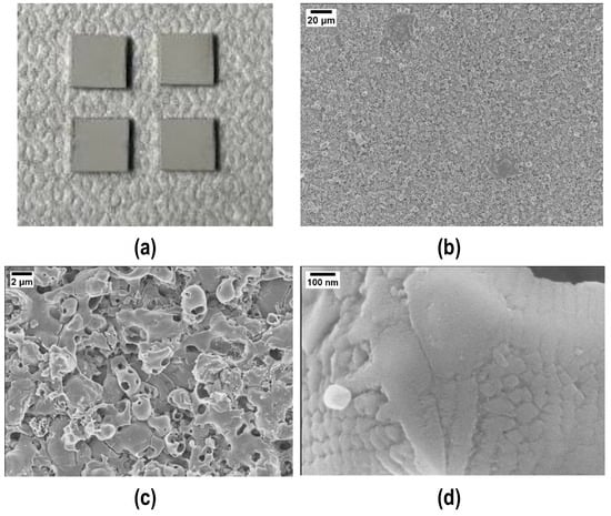
Figure 1.
Visual appearance (a) and higher magnifications (b,c) of the Plasma Electrolytic Oxidated (PEO) alumina-coated aluminum slabs. (d) Evidence of the PEO alumina nanocrystalline structure.
Before performing the TGA analysis up to 1200 °C, the effectiveness of the curing process was verified: about 15 mg of cured polymer was put inside the crucible at an initial temperature of 20 °C, which was kept constant for 5 min; then, a heating rate of 10 °C/min was used to reach the curing temperature of 180 °C, which was kept for 1 h. A weight loss of 0.8% was observed when the temperature reached 180 °C, possibly due to the degradation of non-crosslinked volatile oligomers. After that, there was a further weight loss of 0.1%, followed by a weight increase of 0.3%. These two latter minor weight changes are likely due to buoyancy effects caused by the low weight of the sample (a few milligrams), making any conclusions about mass loss or gain speculative. Since the total weight variation was less than 1%, the curing process was considered successful.
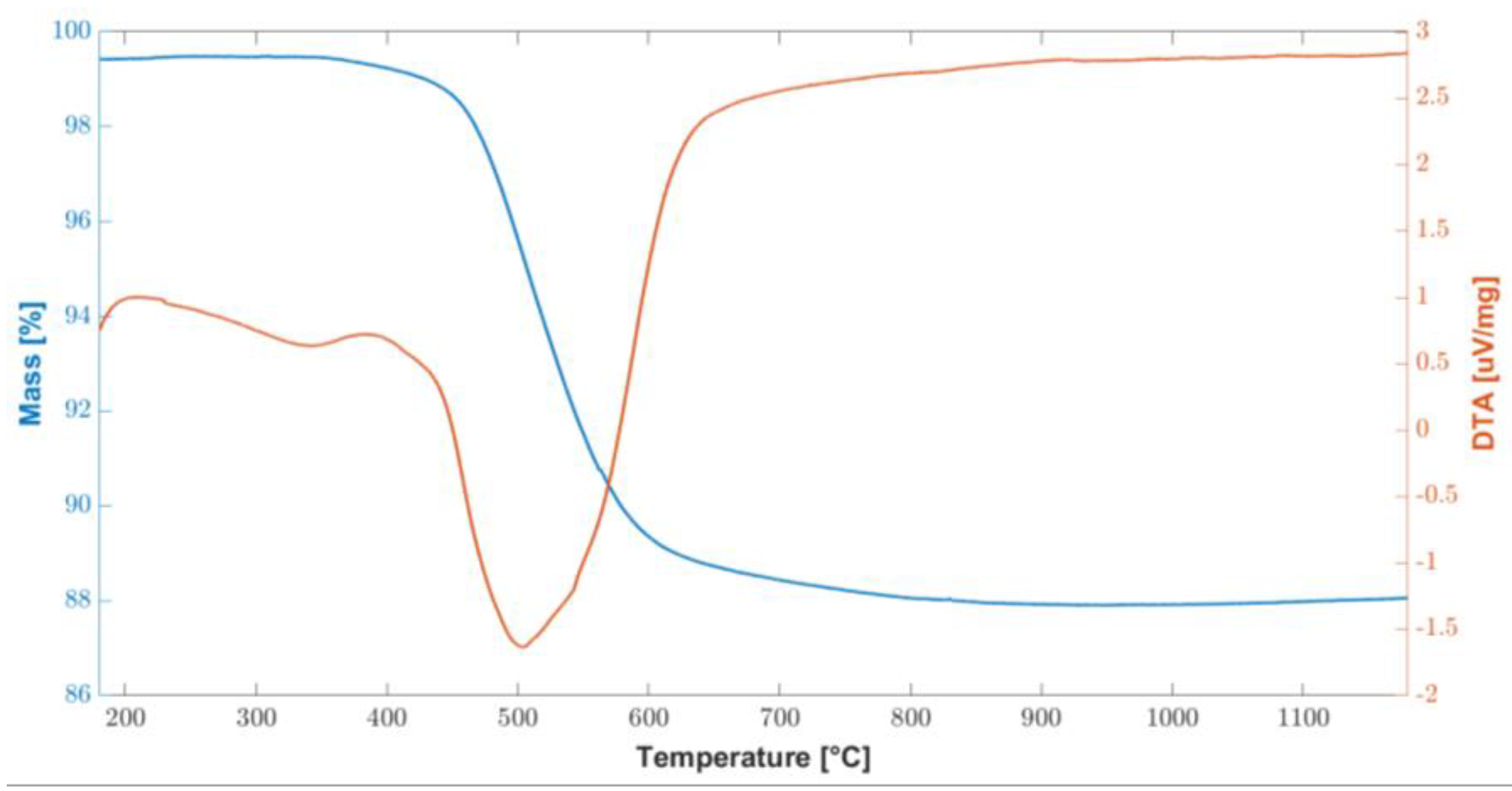
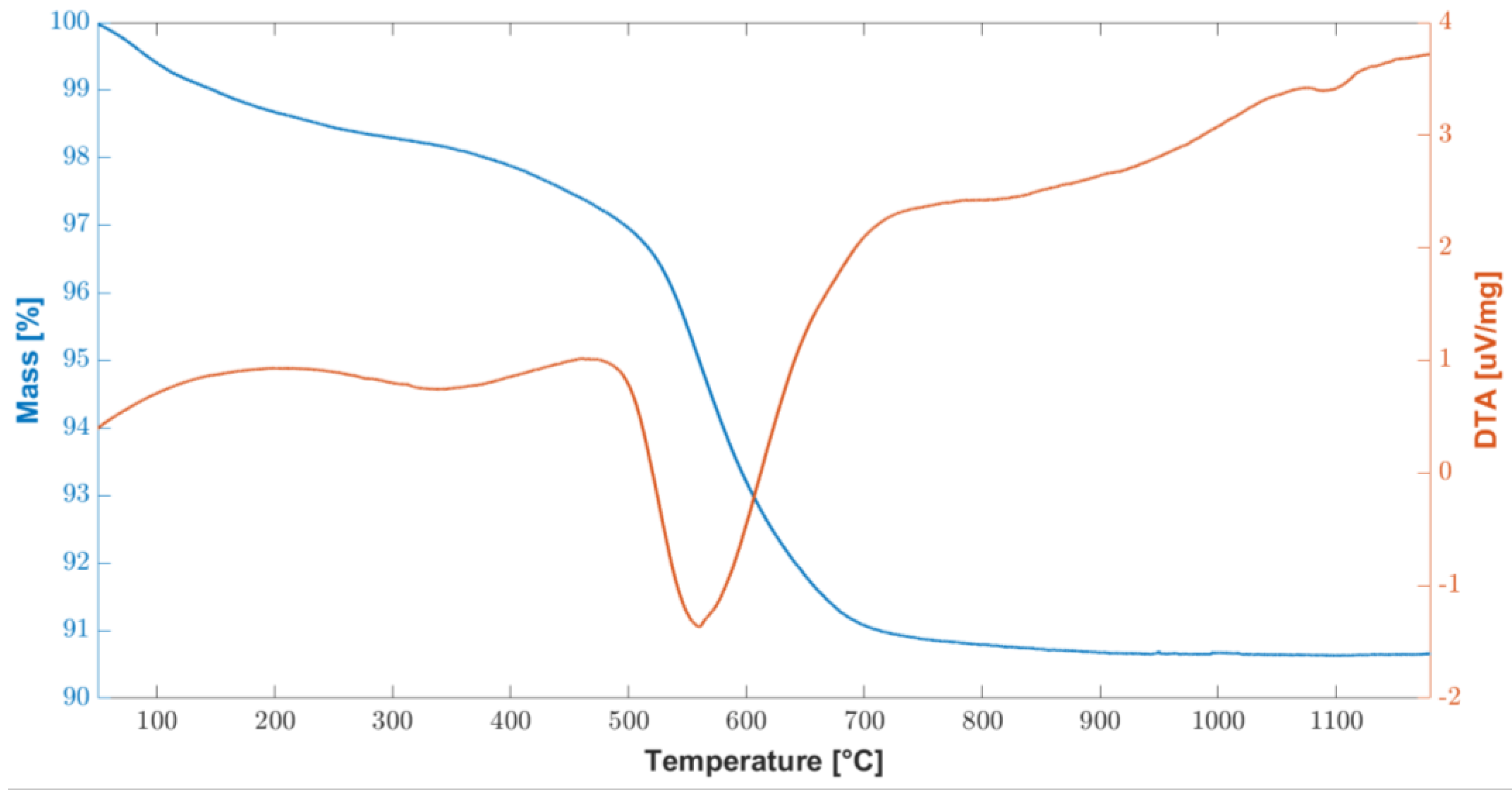
In order to test the thermal stability of the cured polymer, TGA-DTA analysis was carried out and the results are shown in Figure 2. The overall weight loss are about 11% and it was recorded between 450 °C and 600 °C, corresponding to the ceramic conversion process. At about 800 °C, the conversion was completed, and the weight remained stable up to 1200 °C.
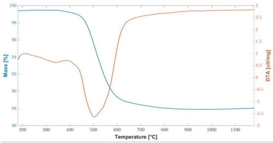
Figure 2.
Combined graph of TGA/DTA curves of the cured polymer up to 1200 °C.
These results are consistent with the information found in the literature [27], in two fundamental steps were identified: the first in the temperature range 200–400 °C and the second at 500–750 °C. In particular, at temperatures above 200 °C, there is a further radical polymerization of residual vinyl groups. Up to 400 °C, further dehydrogenation and transamination reactions occur, although the total mass loss is negligible, as can be seen from the flat TGA curve in Figure 2.
Conversely, between 500 °C and 750 °C, a significant mass loss is associated with the organic–inorganic transformation of the polymer into amorphous silica. This process is also called ceramization and involves the decomposition and transformation of organic groups. During this thermal treatment, known as thermolysis, the organic components undergo significant chemical changes, breaking down and evolving into gaseous byproducts. As the temperature rises within this specified range, the preceramic materials undergo a series of complex chemical reactions. These reactions promote the formation of strong covalent bonds between the remaining elements, leading to the development of an amorphous ceramic structure. This transformation results in the creation of amorphous covalent ceramics (ACC) [38,39,40,41]. While a mass loss of 11.4% was measured between 400 °C and 800 °C, no further mass loss was measured up to the end of the test, at 1200 °C.
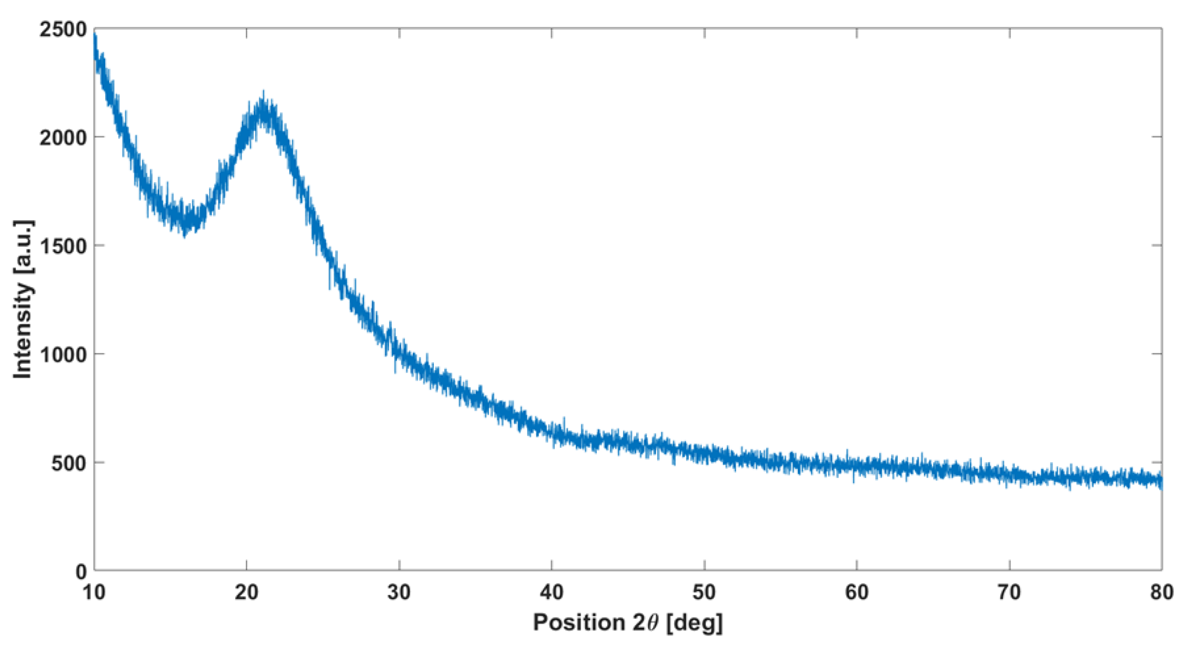
XRD analysis performed on the cured polymer treated at 1200 °C (Figure 3) confirms the amorphous structure of the obtained material: once heated at 1200 °C, the polymer appears colorless. Results in the literature, such as the study by [42], confirm that pyrolysis at this temperature leads to the formation of an amorphous phase.

Figure 3.
XRD analysis on the cured polymer heated at 1200 °C showing the typical amorphous silica halo.
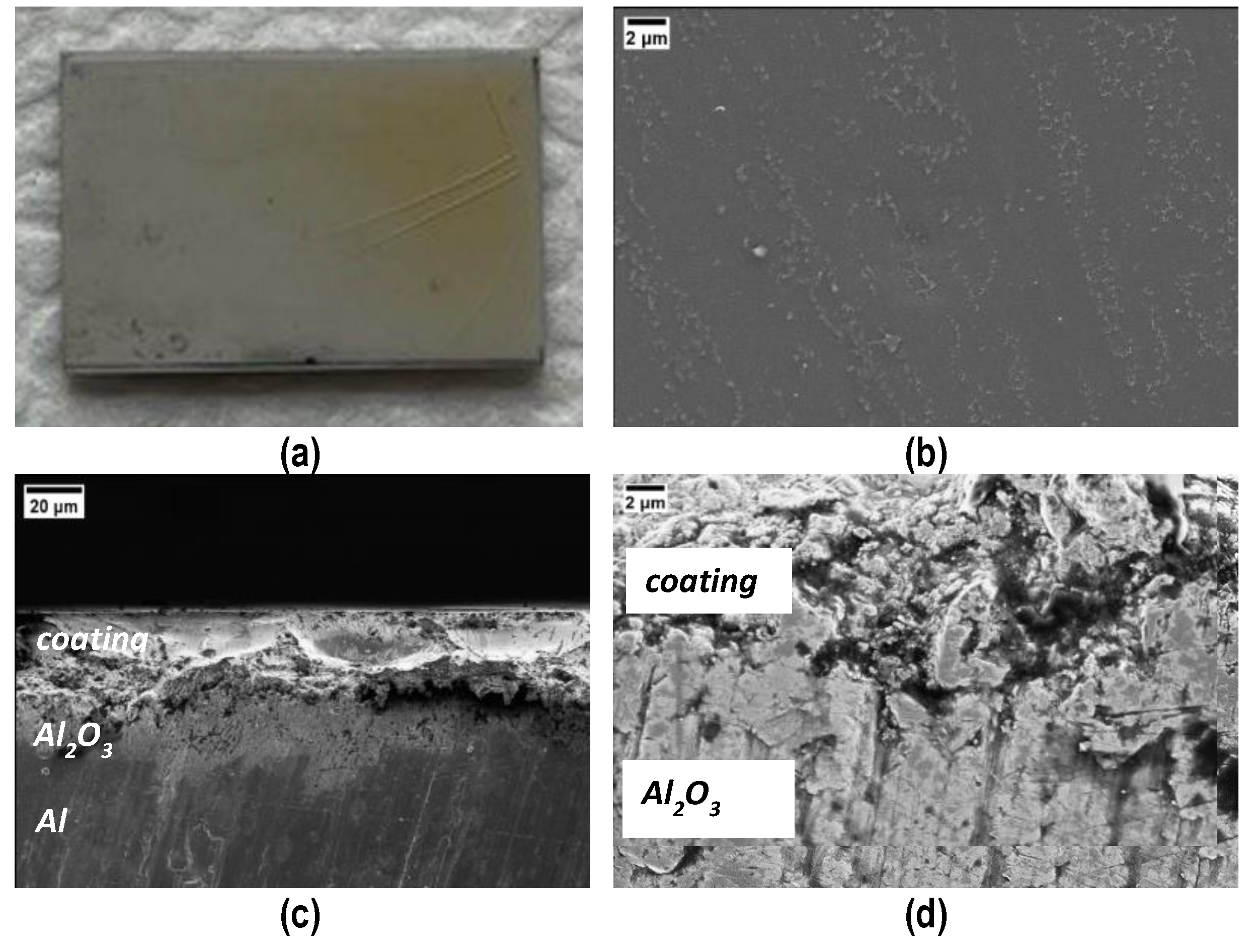
Coated samples were obtained by manually depositing the polymer on the PEO side of the samples, followed by the curing process at 180 °C for 4 h. Figure 4a shows the top surface of the coating after curing; it is compact and shiny, except from some macro-cracks on the right side, probably due to an excessive thickness; the good quality of the coating is also confirmed via FESEM micrographs taken of the top surface (Figure 4b) and the cross sections (Figure 4c,d). Evidence of a sound interface between PEO Al2O3 and cured polymer is visible in Figure 4d.

Figure 4.
Visual (a) and FESEM (b) top view and cross sections (c,d) of the coating after curing. Cracks in (a) the thicker side of the coating. (d) Evidence of a sound interface between PEO Al2O3 and the cured polymer coating.
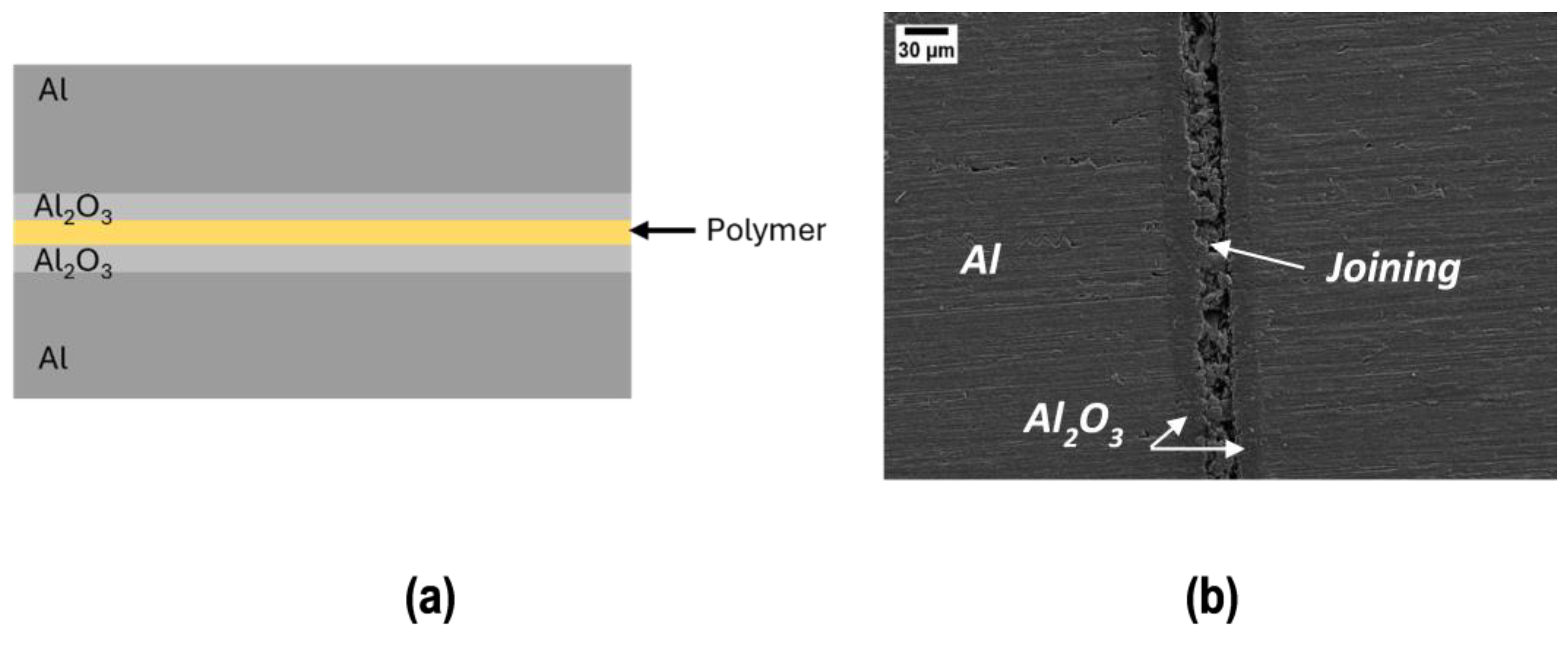
Joined samples were obtained by sandwiching the polymer between two samples (PEO alumina side), as in Figure 5, which shows a schematic representation (a) and a SEM polished cross section of a joined sample (b): residual porosity and cracks due to the polymer evolution (weight loss and shrinkage) upon curing are visible.

Figure 5.
Schematic representation (a) and SEM polished cross section of the joined sample (b).
It is important to point out that in the case of the coating, the entire surface is available for the elimination of volatile species during curing and the coating is compact and pore free; conversely, in the joint, volatile species have only the perimeter to escape during curing. Therefore, joints are more porous than coatings, although they were produced under the same curing conditions.
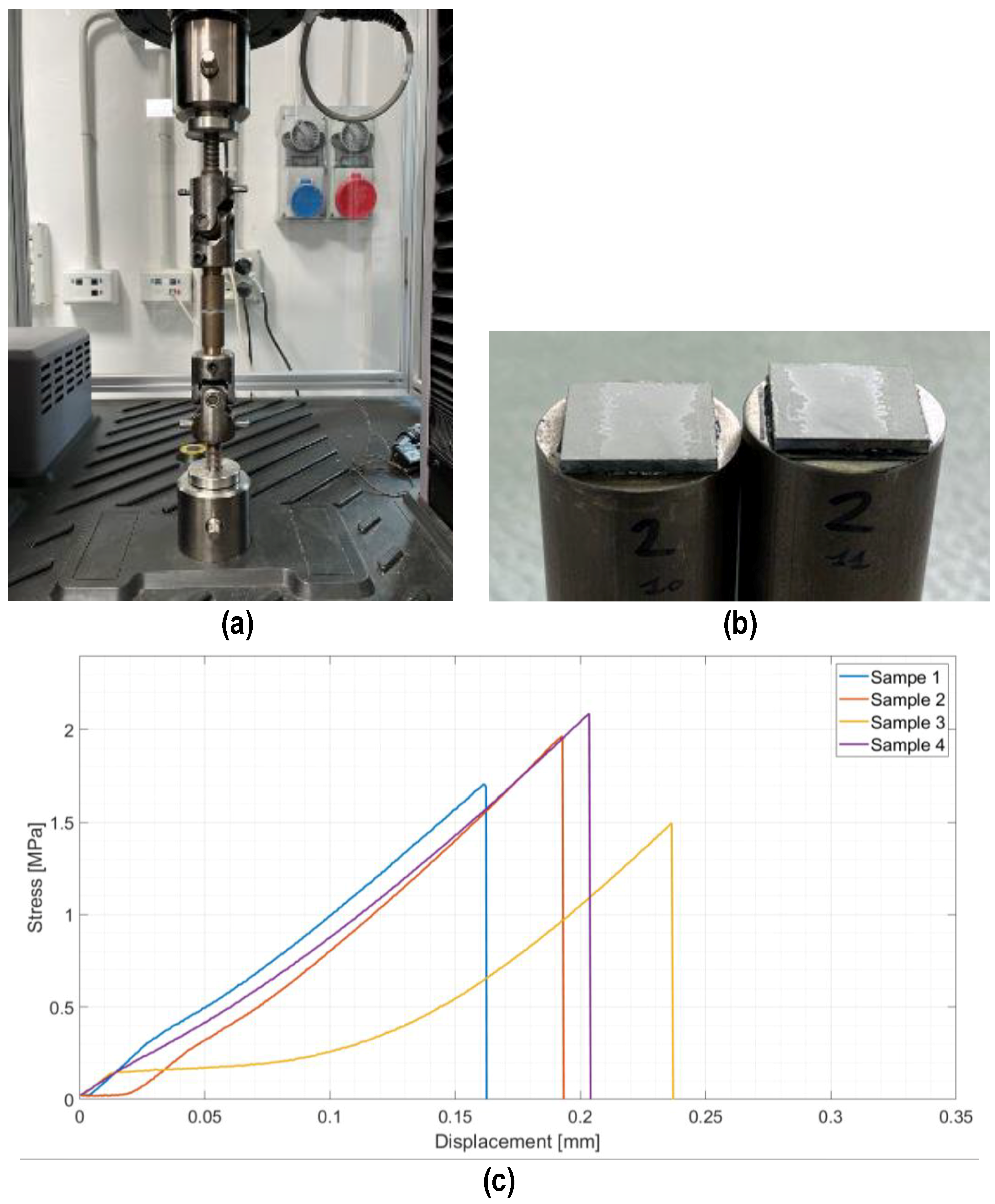
Joined samples were tested in tensile mode according to a modified ASTM C633-01. Figure 6 shows the tensile test set up (a) and the typical cohesive fracture surface of joined samples after the tensile test (b). The joining material is present on both surfaces, typical of a cohesive fracture, indicating a strong interface between the PEO alumina and the coating. Figure 6c shows the stress–displacement diagrams recorded on the four joined samples subjected to the tensile test. The fracture was typically brittle, as expected for silica-based material, with an average tensile strength of 1.8 ± 0.3 MPa.
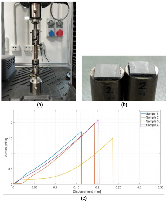
Figure 6.
Tensile test on joined samples: tensile test set up (a), typical fracture surface of a joined sample after tensile test (b), and average tensile strength = 1.8 ± 0.3 MPa (c).
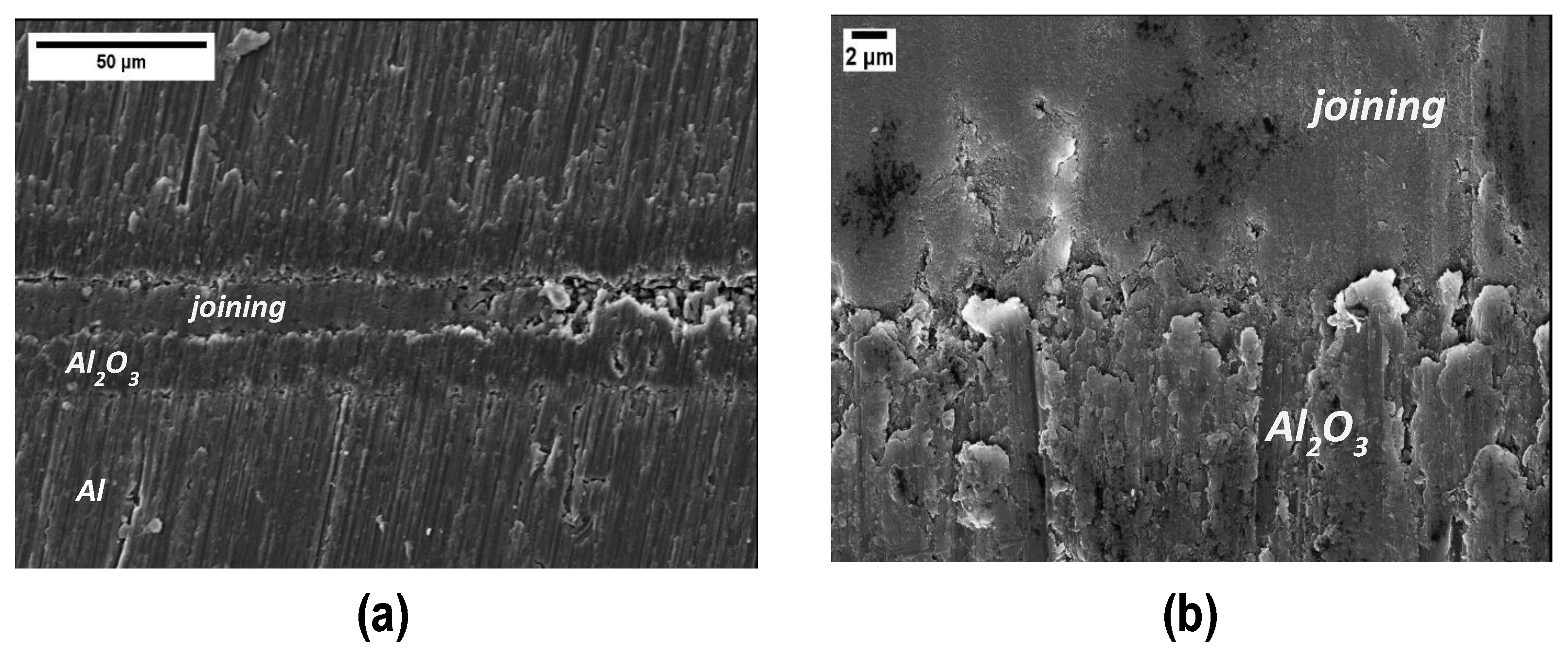
FESEM micrographs of the fracture surfaces after the tensile test are shown in Figure 7: it is possible to distinguish the joining material from the PEO alumina, with the former cracked and the latter smooth (Figure 7a). At higher magnification (Figure 7b), one can observe that the joining material has some porosity and the PEO alumina shows the nanocrystalline structure, already observed in Figure 1.
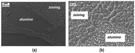
Figure 7.
SEM results on the joined samples’ typical fracture surface after the tensile test (a) and at higher magnification (b).
A punctual EDS analysis was performed in order to measure the elemental composition in different zones of the fracture surface. EDS of the joining material detected the polymer’s main elements, i.e., Si, C, and O, with residual C associated with the non-complete transformation to silica at 180 °C (Figure 3); conversely, the main elements detected in the PEO alumina regions were, as expected: Al and O. While the PEO alumina is clearly visible in some areas of the fracture surfaces, no bare aluminum is visible, confirming the interfacial strength of Al/PEO alumina, which is more intense than the cured polymer/PEO alumina one.
In order to decrease porosity and increase the mechanical strength of the joints, an increasing amount of silica nanoparticles were added to the polymer up to 48 wt%, which was found to be the maximum amount that could be added under these experimental conditions.
As shown in Figure 8 the total weight loss is about 10%, slightly lower than what was found without silica nanoparticles. The TGA curve is very similar to what was found for the polymer without silica nanoparticles in Figure 3; however, for temperatures below 400 °C, there is a higher mass loss (2.2%) associated with the elimination of the most volatile species, probably due to the presence of 48 wt% silica nanoparticles, which facilitate the reaction and the gaseous products elimination path. A significant mass loss of 6% occurs between 500 °C and 700 °C, corresponding to the conversion to amorphous silica.
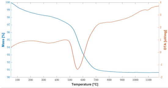
Figure 8.
Combined graph of TGA/DTA curves of the cured polymer loaded with 48 wt% silica nanoparticles up to 1200 °C.
Given the low melting temperature of the Al slabs used for this work, a complete transformation to silica was not possible: however, the presence of 48 wt% of silica nanoparticles improved the mechanical strength of the joints, as discussed below.
According to the literature, an improvement in terms of reduced porosity and increased mechanical strength is expected when adding fillers to compensate for the shrinkage during the curing of a preceramic polymer. The same curing procedure at 180 °C for 4 h in air was used for the preparation of coatings and joints with 48 wt% silica. Since the addition of silica nanoparticles increased the polymer’s viscosity, it was much more difficult to spread the material using the spatula to obtain a thin, uniform layer for the manual deposition. The thicker coatings became significantly more cracked than those produced without silica nanoparticles and they could be peeled off from the substrates very easily: a better deposition process is going to be developed to obtain thinner coatings with silica nanoparticles.
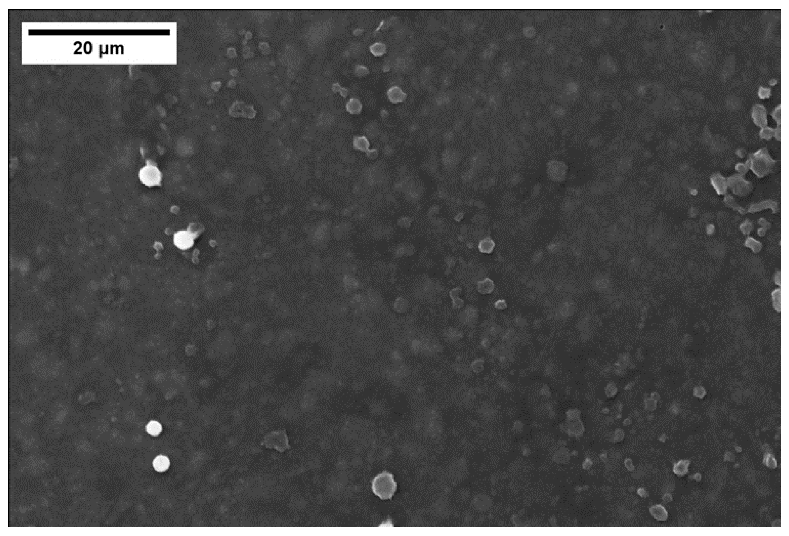
Figure 9 shows a FESEM top view of the coating with 48 wt% of silica nanoparticles: some “clouds” corresponding to non-homogeneously dispersed silica nanoparticles agglomerates can be seen; a better homogenization process should be tested to improve the coating compositional uniformity when silica nanoparticles are added to the polymer. Some studies are already present in the literature about increasing the uniformity of mixing nanoparticles in the polymer [20,43,44]. The EDS analysis of the coating only reported silicon, carbon, and oxygen as detected elements.
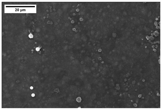
Figure 9.
FESEM top view of the cured polymer coating with 48 wt% silica nanoparticles: “clouds” due to non-optimal silica dispersion.
Conversely, the joints appear sound and resistant to cutting and polishing: Figure 10 shows a representative FESEM cross section of a joint, which is less porous than those obtained using the pure polymer (Figure 5). Some residual porosity is still present, but the higher magnification in Figure 10b shows a fairly good interface between PEO alumina and the joining material.

Figure 10.
SEM cross section of samples joined using the cured polymer loaded with 48 wt% silica nanoparticles (a) and higher magnification of the interface PEO alumina and joining material (b).
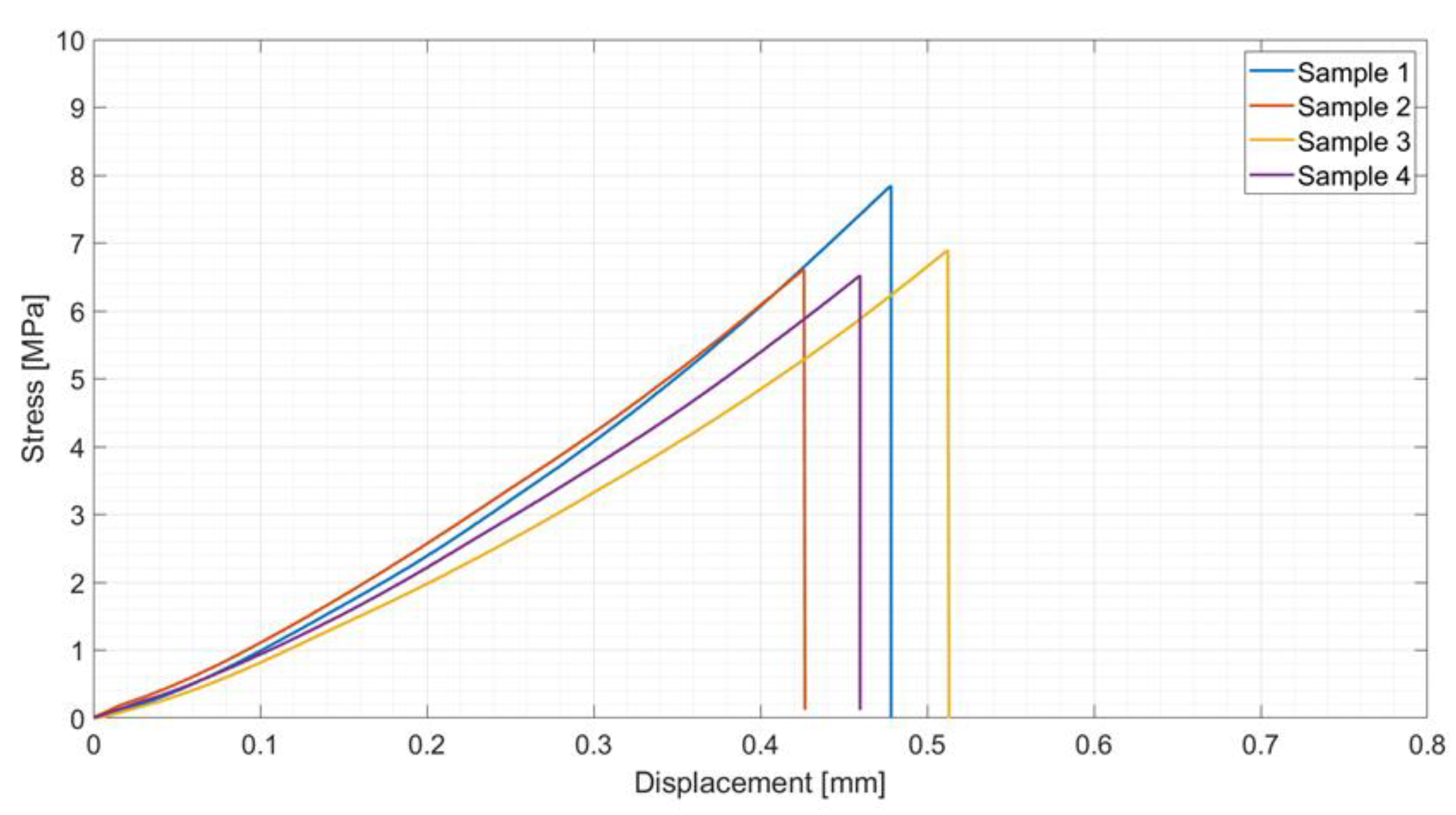
Tensile tests on four of these joined samples gave an average tensile strength of 7.0 ± 0.6 MPa (Figure 11), which is almost four times the values obtained on joints produced by using the polymer only.
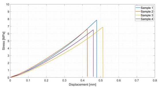
Figure 11.
Tensile test results on samples joined using polymer loaded with 48 wt% silica nanoparticles: average tensile strength = 7.0 ± 0.6 MPa.
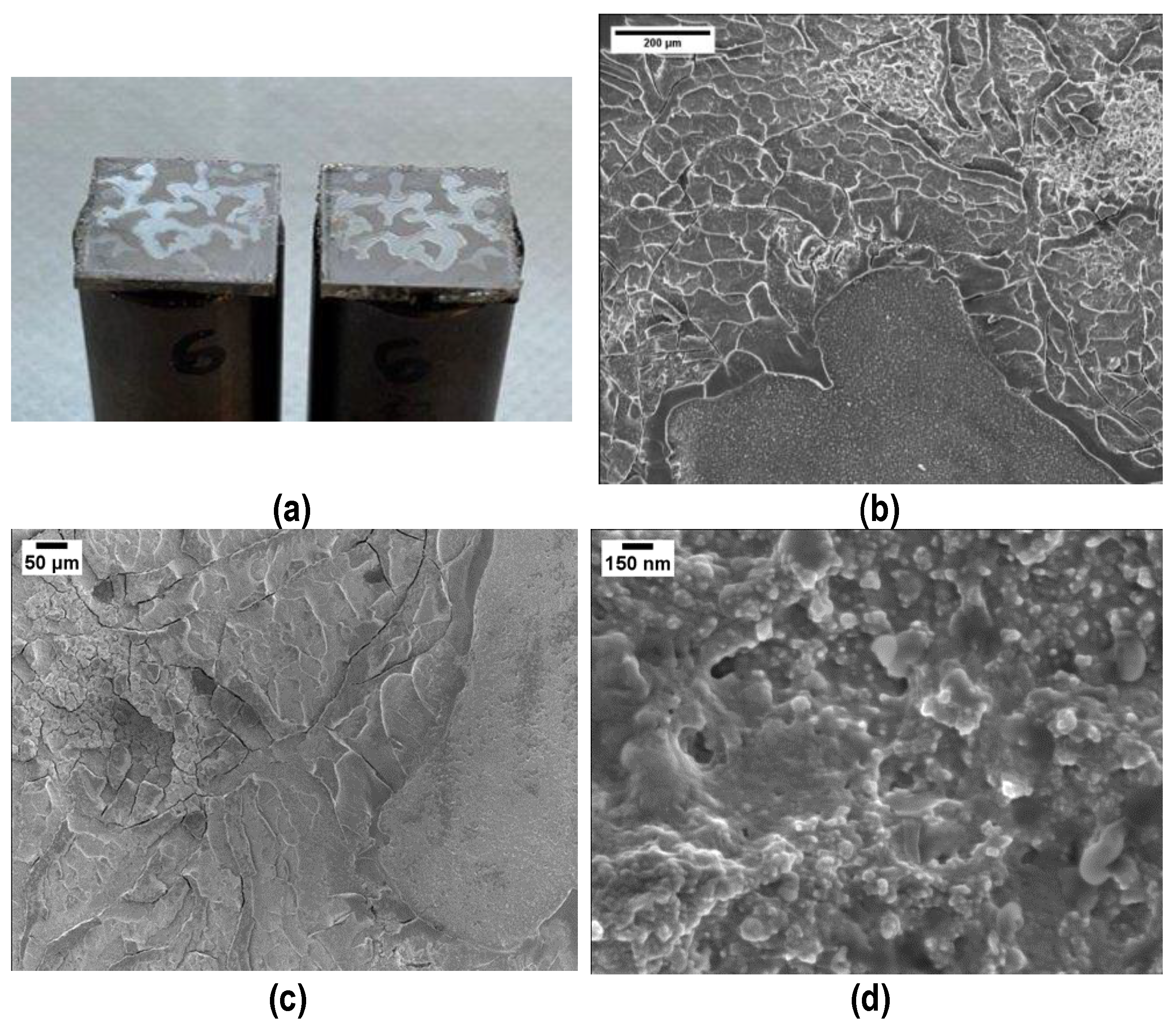
The fracture surfaces after tensile tests clearly show a cohesive fracture mode in all samples (Figure 12a): loading the polymer with silica nanoparticles decreases the joints porosity and increases their mechanical strength, this suggesting that the interface joining material/PEO alumina is stronger than before, as is the cohesion of the joining material. Figure 12 shows FESEM images of the fracture surfaces after tensile tests and the compact structure of the joining material is well visible (Figure 12b), particularly at higher magnification (Figure 12c,d). By comparing these results with those in Figure 7b, it is clear, from a morphological point of view, that the addition of silica nanoparticles improved both the cohesion and mechanical strength of the joints.

Figure 12.
Typical cohesive fracture surface after tensile test on samples joined using polymer loaded with 48 wt% silica nanoparticles: visual appearance (a) and FESEM (b–d) of the joining material.
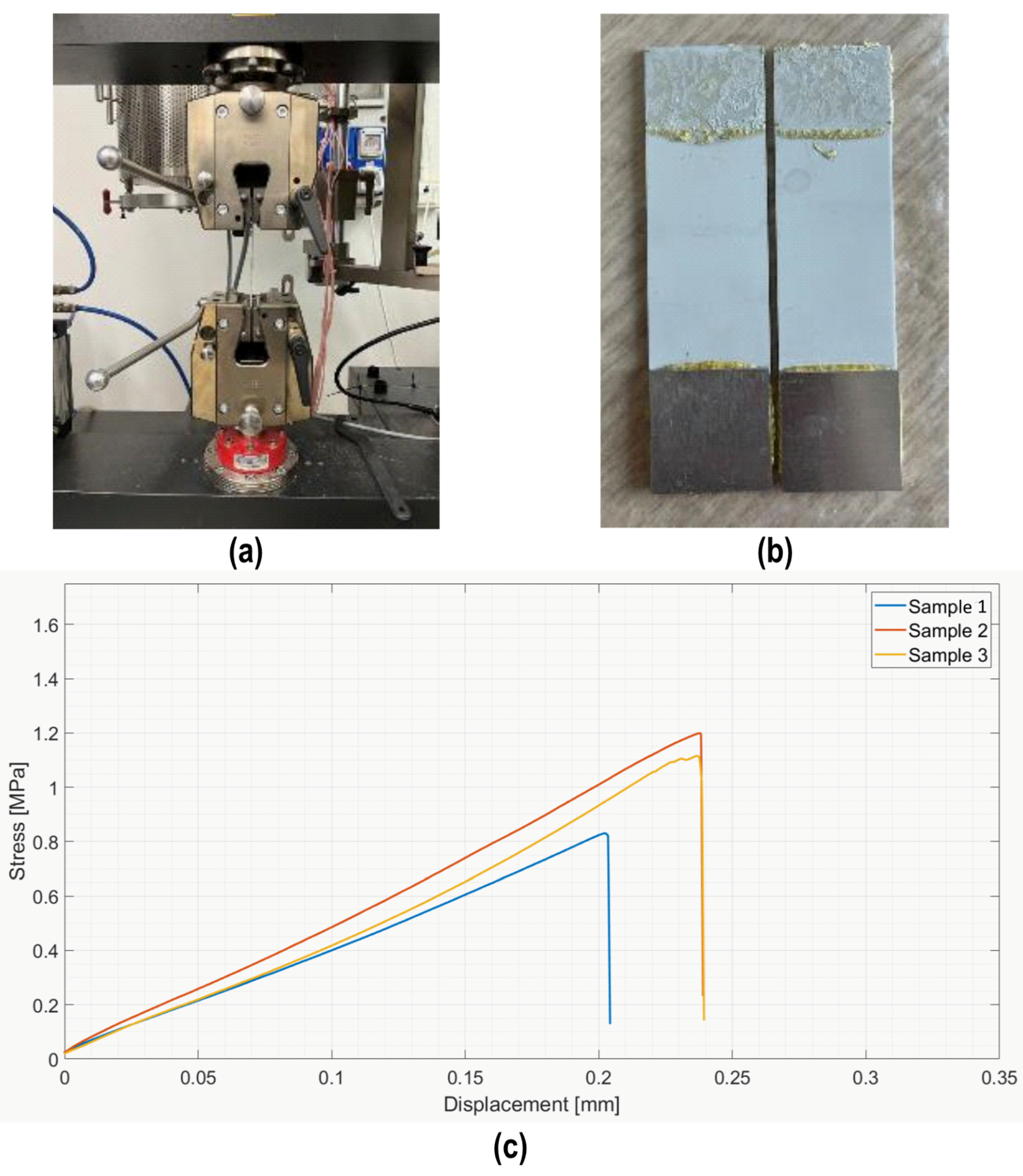
Given these promising results, these joints were further characterized using a tensile single lap test, according to ASTM D1002-10 [37], as shown in Figure 13: a typical cohesive fracture surface (b) was found on all samples, as reported for the tensile tests. The average lap strength was 1.2 ± 0.3 MPa and the curves show the expected brittle behavior (Figure 13c). The lower value measured for lap shear strength in tensile mode was due to the presence of bending modes, which are absent when the measure is conducted as in Figure 6.

Figure 13.
Single lap test in tensile mode (a) on samples joined using polymer loaded with 48 wt% silica nanoparticles (AISI D1002-10); typical cohesive fracture surface (b); and average lap strength = 1.15 ± 0.3 MPa (c).
In order to understand the mechanical resistance of the coatings better, Computed Tomography with in situ bending tests was performed on the aluminum slabs coated with the polymer and cured, as described above and by using the fixture shown in Figure 14a, where the position of the supporting pins (A), loading pins (B), and CFRP rod (C), which transfers the load, are highlighted.
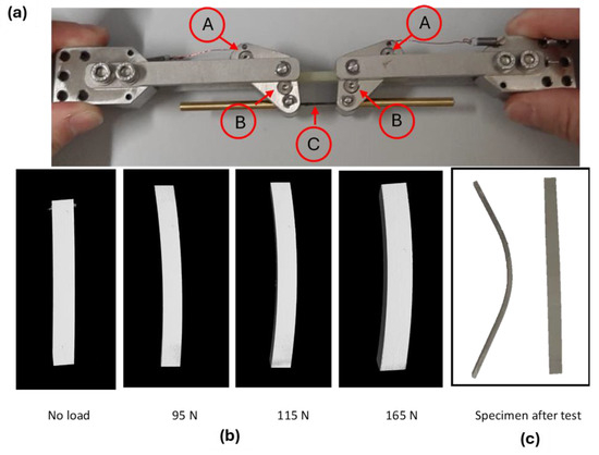
Figure 14.
CT-scan in situ bending tests at different loading conditions on PEO alumina aluminum slabs, coated with the polymer and cured. Set up for the in situ bending test (a). Transversal section of the reconstructed 3D model via CT-scan (b). Specimen after test (c).
The transversal sections of the reconstructed 3D volumes via CT-scan are reported in Figure 14b and the sample after test is visible in Figure 14c: the first crack appearance on the coating was observed at a bending load of 115 N. The measured bending stress on the coating was 570 MPa.
Figure 15 shows the cracks visible in the tomography reconstruction (b) and the FESEM inspection of the same surface (c).
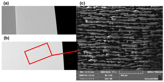
Figure 15.
Surface tomography inspection of the non-loaded PEO aluminum slabs coated and cured, without cracks (a). First appearance of cracks on the coating during in situ bending test during tomography (b). Higher magnification of the cracks via FESEM (c).
Finally, the produced coatings were always characterized by outstanding resistance in the humid environment, with the recorded weight loss after one week soaking in tap water at room temperature always equal to zero.
4. Conclusions
The suitability of a silica preceramic polymer for joining and coating Plasma Electrolytic Oxidated (PEO) aluminum components at temperatures below 200 °C was demonstrated in this study.
The incorporation of a passive filler, specifically nanometric amorphous silica, enabled effective control over the critical aspects of the crosslinking process, resulting in significant enhancements in both joint morphology and mechanical strength. This advancement transitioned the joint from one characterized by numerous voids and cracks to a much denser and more compact structure, capable of achieving an average tensile strength of approximately 7 MPa, which is four times greater than that achieved using the pure polymer.
The bending stress at which the first crack appeared on the coating was notably 570 MPa, extending the potential applications of this coating to environments that require substantial mechanical resistance.
The water resistance, preliminarily assessed by soaking the coated samples in tap water for one week, yielded excellent results.
Further improvements in the mixing process for silica nanoparticles, as well as the coating deposition, joining procedure, and thickness, are likely to enhance the mechanical strength of the samples.
Finally, for applications requiring higher temperatures, this polymer presents itself as an intriguing joining and coating material capable of producing pure amorphous silica at approximately 800 °C.
This study explored the use of a silica preceramic polymer for joining and coating Plasma Electrolytic Oxidated aluminum components and the resistance to humid environments has been studied. The results suggest that this material, used as a joining or coating material, has potential for broader applications, including components working in harsh conditions. As a consequence, further investigations will address the behavior of this material in several liquid media showing ranges of pH values. Moreover, in the future, the influence of different wt% of silica nanoparticles will be further investigated.
Author Contributions
Conceptualization, M.F., V.M.S. and P.S.; methodology, M.F., V.C. and V.M.S.; validation, V.C. and A.B.; formal analysis, A.B.; investigation, V.C. and A.B.; resources, V.C. and A.B.; writing—original draft preparation, M.F. and A.B.; writing—review and editing, M.F., V.M.S., P.S. and V.C.; visualization, A.B.; supervision, M.F., V.M.S. and V.C.; project administration, M.F. and V.M.S.; funding acquisition, M.F. All authors have read and agreed to the published version of the manuscript.
Funding
This research received no external funding.
Institutional Review Board Statement
Not applicable.
Informed Consent Statement
Not applicable.
Data Availability Statement
Data is contained within the article.
Acknowledgments
The authors would like to thank Peter Krueger, IKTS-Fraunhofer Institute, Dresden, Germany, for providing the bending fixture for the CT-scan in situ mechanical tests and G. Soraru’ and M. Biesuz at Trento University, Italy for useful discussions about the use of this polymer. A special thanks to Virginia Pastorelli, who prepared and characterized some of the samples during her master thesis at Politecnico di Torino (2023).
Conflicts of Interest
Pavel Shashkov is employed by Cambridge Nanolitic Ltd. The funders had no role in the design of the study; in the collection, analyses, or interpretation of data; in the writing of the manuscript; or in the decision to publish the results.
References
- Rahimi, S.; Khiabani, A.B.; Yarmand, B.; Kolahi, A. Comparison of Corrosion and Antibacterial Properties of Al Alloy Treated by Plasma Electrolytic Oxidation and Anodizing Methods. 2018. Available online: www.sciencedirect.comwww.materialstoday.com/proceedings2214-7853 (accessed on 11 June 2024).
- Ropyak, L.; Shihab, T.; Velychkovych, A.; Bilinskyi, V.; Malinin, V.; Romaniv, M. Optimization of Plasma Electrolytic Oxidation Technological Parameters of Deformed Aluminum Alloy D16T in Flowing Electrolyte. Ceramics 2023, 6, 146–167. [Google Scholar] [CrossRef]
- Budunoglu, H.; Yildirim, A.; Bayindir, M. Flexible and mechanically stable antireflective coatings from nanoporous organically modified silica colloids. J. Mater. Chem. 2012, 22, 9671–9677. [Google Scholar] [CrossRef]
- Chi, F.; Yan, L.; Yan, H.; Jiang, B.; Lv, H.; Yuan, X. Ultralow-refractive-index optical thin films through nanoscale etching of ordered mesoporous silica films. Opt. Lett. 2012, 37, 1406–1408. [Google Scholar] [CrossRef]
- Castro, Y.; Ferrari, B.; Moreno, R.; Dur’an, A.; Dur’an, D. Silica Sol-Gel Coatings on Metals Produced by EPD. J. Sol-Gel Sci. Technol. 2003, 26, 735–739. [Google Scholar] [CrossRef]
- Raut, H.K.; Ganesh, V.A.; Nair, A.S.; Ramakrishna, S. Anti-reflective coatings: A critical, in-depth review. Energy Environ. Sci. 2011, 4, 3779–3804. [Google Scholar] [CrossRef]
- Kócs, L.; Késmárki, A.; Klébert, S.; Madarász, J.; Hórvölgyi, Z. Plasma-assisted template removal and consolidation of silica coatings on polycarbonate. Thin Solid Film. 2021, 738, 138976. [Google Scholar] [CrossRef]
- Kócs, L.; Albert, E.; Tegze, B.; Kabai-Faix, M.; Major, C.; Szalai, A.; Basa, P.; Hórvölgyi, Z. Silica Sol-gel coatings with improved light transmittance and stability. Period. Polytech. Chem. Eng. 2018, 62, 21–31. [Google Scholar] [CrossRef]
- Barnes, T.A.; Pashby, I.R. Joining techniques for aluminium spaceframes used in automobiles Part II Ð adhesive bonding and mechanical fasteners. J. Mater. Process. Technol. 2000, 99, 72–79. [Google Scholar] [CrossRef]
- Lunder, O.; Olsen, B.; Nisancioglu, K. Pre-treatment of AA6060 aluminium alloy for adhesive bonding. Int. J. Adhes. Adhes. 2002, 22, 143–150. [Google Scholar] [CrossRef]
- Cavezza, F.; Boehm, M.; Terryn, H.; Hauffman, T. A review on adhesively bonded aluminium joints in the automotive industry. Metals 2020, 10, 730. [Google Scholar] [CrossRef]
- Petrie, E.M. How moisture affects adhesives, sealants, and coatings. Met. Finish. 2011, 109, 36–37+48. [Google Scholar] [CrossRef]
- Del Real, J.C.; De Santayana, M.C.; Abenojar, J.; Martinez, M.A. Adhesive bonding of aluminium with structural acrylic adhesives: Durability in wet environments. J. Adhes. Sci. Technol. 2006, 20, 1801–1818. [Google Scholar] [CrossRef]
- Fu, S.; Zhu, M.; Zhu, Y. Organosilicon polymer-derived ceramics: An overview. J. Adv. Ceram. 2019, 8, 457–478. [Google Scholar] [CrossRef]
- Ren, Z.; Bin Mujib, S.; Singh, G. High-temperature properties and applications of Si-based polymer-derived ceramics: A review. Materials 2021, 14, 614. [Google Scholar] [CrossRef] [PubMed]
- Chaudhary, R.P.; Parameswaran, C.; Idrees, M.; Rasaki, A.S.; Liu, C.; Chen, Z.; Colombo, P. Additive manufacturing of polymer-derived ceramics: Materials, technologies, properties and potential applications. Prog. Mater. Sci. 2022, 128, 100969. [Google Scholar] [CrossRef]
- Colombo, P.; Mera, G.; Riedel, R.; Sorarù, G.D. Polymer-derived ceramics: 40 Years of research and innovation in advanced ceramics. J. Am. Ceram. Soc. 2010, 93, 1805–1837. [Google Scholar] [CrossRef]
- Barroso, G.; Li, Q.; Bordia, R.K.; Motz, G. Polymeric and ceramic silicon-based coatings-a review. J. Mater. Chem. A 2019, 7, 1936–1963. [Google Scholar] [CrossRef]
- Greil, P. Polymer derived engineering ceramics. Adv. Eng. Mater. 2000, 2, 339–348. [Google Scholar] [CrossRef]
- Bernardo, E.; Fiocco, L.; Parcianello, G.; Storti, E.; Colombo, P. Advanced ceramics from preceramic polymers modified at the nano-scale: A review. Materials 2014, 7, 1927–1956. [Google Scholar] [CrossRef]
- Colombo, P.; Riedel, R.; Soraru, G.D.; Kleebe, H.-J. Polymer Derived Ceramics: From Nano-Structure to Applications; Destech Pubns Inc.: Lancaster, PA, USA, 2010. [Google Scholar]
- Bala Srinivasan, P.; Zettler, R.; Blawert, C.; Dietzel, W. A study on the effect of plasma electrolytic oxidation on the stress corrosion cracking behaviour of a wrought AZ61 magnesium alloy and its friction stir weldment. Mater. Charact. 2009, 60, 389–396. [Google Scholar] [CrossRef]
- Shore, D.; Avelar-Batista Wilson, J.C.; Matthews, A.; Yerokhin, A. Adhesive bond strength of PEO coated AA6060-T6. Surf. Coat Technol. 2021, 428, 127898. [Google Scholar] [CrossRef]
- Aliasghari, S.; Skeldon, P.; Zhou, X.; Ghorbani, M. Influence of PEO and mechanical keying on the strength of AA 5052 alloy/polypropylene friction stir spot welded joints. Int. J. Adhes. Adhes. 2019, 92, 65–72. [Google Scholar] [CrossRef]
- Aliasghari, S.; Ghorbani, M.; Skeldon, P.; Karami, H.; Movahedi, M. Effect of plasma electrolytic oxidation on joining of AA 5052 aluminium alloy to polypropylene using friction stir spot welding. Surf. Coat Technol. 2017, 313, 274–281. [Google Scholar] [CrossRef]
- Shashkov, P.; Khomutov, G.; Yerokhin, A.; Usov, S. Non-Metallic Coating and Method of Its Production. U.S. Patent 9,677,187,B2, 13 June 2017. [Google Scholar]
- Bousser, E.; Rogov, A.; Shashkov, P.; Gholinia, A.; Laugel, N.; Slater, T.J.A.; Withers, P.J.; Matthews, A.; Yerokhin, A. Phase transitions in alumina films during post-sparking anodising of Al alloys. Acta Mater. 2023, 244, 118587. [Google Scholar] [CrossRef]
- Kgaa, M. Technical Datasheet 214049 Durazane® 1800. Available online: https://www.merckgroup.com/Products/PM/global/TDS_214049_Durazane_1800_Merck.pdf (accessed on 26 April 2024).
- Horcher, A.; Tangermann-Gerk, K.; Krenkel, W.; Schafföner, S.; Motz, G. Advanced ceramic coatings on aluminum by laser treatment of filled organosilazane-based composites. Ceram. Int. 2022, 48, 23284–23292. [Google Scholar] [CrossRef]
- Liu, J.; Qiao, Y.L.; Zhang, P.; Xue, Y.C.; Cai, Z. Synthesis of SiC ceramics from polysilazane by laser pyrolysis. Surf. Coat Technol. 2017, 321, 491–495. [Google Scholar] [CrossRef]
- Gardelle, B.; Duquesne, S.; Vu, C.; Bourbigot, S. Thermal degradation and fire performance of polysilazane-based coatings. Thermochim. Acta 2011, 519, 28–37. [Google Scholar] [CrossRef]
- Barroso, G.; Döring, M.; Horcher, A.; Kienzle, A.; Motz, G. Polysilazane-Based Coatings with Anti-Adherent Properties for Easy Release of Plastics and Composites from Metal Molds. Adv. Mater. Interfaces 2020, 7, 1901952. [Google Scholar] [CrossRef]
- Qazzazie-Hauser, A.; Honnef, K.; Hanemann, T. Crosslinking behavior of UV-cured polyorganosilazane as polymer-derived ceramic precursor in ambient and nitrogen atmosphere. Polymers 2021, 13, 2424. [Google Scholar] [CrossRef] [PubMed]
- ASTM C633-01; Standard Test Method for Adhesion or Cohesion Strength of Thermal Spray Coatings. ASTM International: West Conshohocken, PA, USA, 2010.
- Baino, F.; Vitale-Brovarone, C. Wollastonite-containing bioceramic coatings on alumina substrates: Design considerations and mechanical modelling. Ceram. Int. 2015, 41, 11464–11470. [Google Scholar] [CrossRef]
- D’Isanto, F.; Salvo, M.; Molin, S.; Koszelow, D.; Javed, H.; Akram, S.; Chrysanthou, A.; Smeacetto, F. Glass-ceramic joining of Fe22Cr porous alloy to Crofer22APU: Interfacial issues and mechanical properties. Ceram. Int. 2022, 48, 28519–28527. [Google Scholar] [CrossRef]
- ASTM D1002-10; Standard Test Method for Apparent Shear Strength of Single-Lap-Joint Adhesively Bonded Metal Specimens by Tension Loading (Metal-to-Metal). ASTM International: West Conshohocken, PA, USA, 2019. [CrossRef]
- Santhosh, B.; Biesuz, M.; Sorarù, G.D. Thermal properties of dense polymer-derived SiCN(O) glasses. Mater. Lett. 2021, 288, 129336. [Google Scholar] [CrossRef]
- Sorarù, G.D.; Tavonatti, C.; Kundanati, L.; Pugno, N.; Biesuz, M. Effect of the pyrolysis atmosphere on the mechanical properties of polymer-derived SiOC and SiCN. J. Am. Ceram. Soc. 2020, 103, 6519–6530. [Google Scholar] [CrossRef]
- Santhosh, B.; Vakifahmetoglu, C.; Ionescu, E.; Reitz, A.; Albert, B.; Sorarù, G.D. Processing and thermal characterization of polymer derived SiCN(O) and SiOC reticulated foams. Ceram. Int. 2020, 46, 5594–5601. [Google Scholar] [CrossRef]
- Ionescu, E.; Kleebe, H.J.; Riedel, R. Silicon-containing polymer-derived ceramic nanocomposites (PDC-NCs): Preparative approaches and properties. Chem. Soc. Rev. 2012, 41, 5032–5052. [Google Scholar] [CrossRef]
- Lenz Leite, M.; Viard, A.; Galusek, D.; Motz, G. In Situ Generated β-Yb2Si2O7 Containing Coatings for Steel Protection in Extreme Combustion Environments. Adv. Mater. Interfaces 2021, 8, 2100384. [Google Scholar] [CrossRef]
- Nguyen, V.S.; Rouxel, D.; Vincent, B. Dispersion of nanoparticles: From organic solvents to polymer solutions. Ultrason. Sonochem. 2014, 21, 149–153. [Google Scholar] [CrossRef]
- Krishnamoorti, R. Strategies for Dispersing Nanoparticles in Polymers. MRS Bull. 2007, 32, 341–347. [Google Scholar] [CrossRef]


Disclaimer/Publisher’s Note: The statements, opinions and data contained in all publications are solely those of the individual author(s) and contributor(s) and not of MDPI and/or the editor(s). MDPI and/or the editor(s) disclaim responsibility for any injury to people or property resulting from any ideas, methods, instructions or products referred to in the content. |
© 2024 by the authors. Licensee MDPI, Basel, Switzerland. This article is an open access article distributed under the terms and conditions of the Creative Commons Attribution (CC BY) license (https://creativecommons.org/licenses/by/4.0/).