Article

Failure Causes Analysis of Circumferential Cracking on Gathering Pipeline in M Oil and Gas Field

1
State Key Laboratory for Performance and Structure Safety of Petroleum Tubular Goods and Equipment Materials, CNPC Tubular Goods Research Institute, Xi’an 710077, China
2
Key Laboratory of Petroleum Tubular Goods and Equipment Ouality Safety for State Market Regulation, Xi’an 710077, China
3
Logging & Testing Services Company, Daqing Oilfield Company Ltd., Daqing 163255, China
4
Oil and Gas Technology Institute of Changqing Oilfield Company, Xi’an 710021, China
*
Author to whom correspondence should be addressed.
Coatings 2024, 14(6), 770; https://doi.org/10.3390/coatings14060770
Submission received: 18 May 2024 / Revised: 14 June 2024 / Accepted: 15 June 2024 / Published: 18 June 2024
(This article belongs to the Special Issue Corrosion/Wear Mechanisms and Protective Methods)

Abstract

:
The gathering and transportation pipeline experienced corrosion cracking failure after 2 years of operation. This paper conducted an analysis on the reasons for the pipeline failure by integrating background information on its usage, as well as observations, analyses, and detection of the morphology of failure samples. The results indicated that the fracture originated from the inner wall of the pipeline and extended to the outer wall along the wall thickness until complete fracture occurred. Based on microstructure analysis of the fracture and original microcracks at the top of the pipeline, it was determined that the fracture was a multi-source brittle fracture, spreading in both inter-granular and trans-granular forms with obvious radial quasi-cleavage fractures accompanied by secondary cracks. EDS analysis revealed that the element S was present in all zones related to fracture initiation, spreading, and transient zones. XRD analysis showed that corrosion products on the fracture surface were mainly composed of FeS, indicating the presence of H2S in the service environment leading to sulfide stress corrosion cracking characteristics in line with pipeline failure. It is recommended to confirm the source of H2S in the service medium and test residual stress within the same pipeline for potential risk assessment regarding cracking in other areas.

1. Introduction

With the growing demand for energy and the intensified exploitation of oilfields, most oil and gas wells have entered the middle and late stages of production. In particular, with the implementation of tertiary oil recovery technology [1,2,3], the environmental conditions of produced oil and gas media have become more complex and challenging. Not only does the service environment of the oil casing pose challenges, but the use environment of the gathering and transportation pipeline is also more severe, including factors such as formation water, corrosion product deposition, bacterial corrosion, etc. The most significant influencing factor is the presence of H2S corrosive gas in the production liquid. In addition, gathering and transportation pipelines are generally buried underground, and the service status of pipelines can be affected by geology and man-made features at any time, and external forces such as collapse or extrusion will affect the service life of pipelines. Therefore, the synergistic effect of multiple factors in complex service conditions often leads to frequent pipeline perforation, leakage, and even cracking failures in service operations, resulting in continuous accidents [4,5]. Based on a variety of failure accidents, researchers have analyzed different kinds of failure causes: Chen Di [6] et al. studied the causes of bending cracking of crude oil gathering and transportation pipelines, and they showed that the synergistic effect of material quality, water content, associated gas (H2S), and low stress led to the sulfide stress corrosion cracking of pipelines. Xiong Gang et al. [7] analyzed the failure characteristics of acid natural gas gathering and transportation pipelines, discussed the corrosion failure risk identification of acid natural gas environment pipelines, and analyzed the three failure characteristics, including stress corrosion cracking, internal corrosion thinning, and blockage, so as to take targeted integrity management measures to reduce the risk of gathering and transportation pipelines’ operation. Chen Lijuan et al. [8] analyzed the corrosion failure causes of surface oil pipes in an overseas high-sulfur and high-salt oilfield, and they showed that dirt was deposited at the bottom of the pipeline during surface pipeline operation due to low crude oil flow rate, high water content, and delayed pipe cleaning, all of which created favorable conditions for the breeding and propagation of bacteria such as sulfate-reducing bacteria (SRB). Kane et al. [9] analyzed the full-scale testing of pipelines with surface defects in H2S and non-H2S environments and analyzed the influence of crack growth in different environments, which is of great significance for the improvement of API standards. Paul Cernocky et al. [10] analyzed the probability method for pipe crack initiation failure and crack propagation failure in the H2S environment and pointed out that the controlling factors tend to be different for the initiation and propagation failure modes. Therefore, it is necessary to determine the main influencing factors and adopt corresponding experimental methods in failure analysis. In order to understand the failure mechanism, failure causes, and main influencing factors of the pipeline, this paper conducts comprehensive detection and analysis on the failure samples according to the background information and failure topography, and identifies the main failure causes.
This study provides a reliable theoretical basis for improving the service life of the pipeline in the oilfield. Meanwhile, it provides scientific and reasonable suggestions for the next step to prevent and mitigate pipeline failure [11].

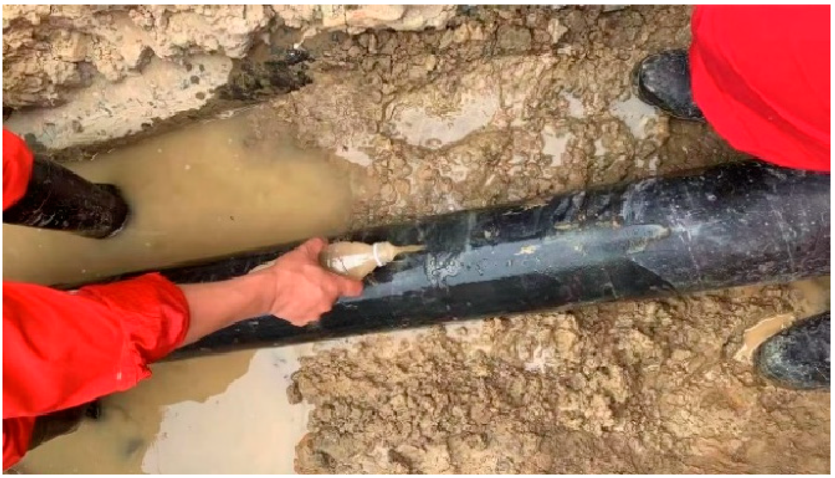
2. Failure Sample Information

The gathering pipeline failed due to corrosion cracking after 2 years of operation. The pipeline, identified as an L360N seamless pipe with dimensions of Φ 168 mm × 6.3 mm, was used for transporting shale gas (wet gas) containing a small amount of CO2 and suspected H2S gas. The two ends of the pipeline were welded. The service temperature was about 30 °C ± 2 °C, and the operating pressure was 2.1 MPa. Failure analysis was conducted on a 600 mm pipe sample received from an oil and gas field (see Figure 1). The gathering pipeline, treated with a corrosion inhibitor and bactericide for antiseptic purposes, was put into operation in April 2021 but experienced cracking and failure in late June 2023.
The extracted failure sample from the site is illustrated in Figure 2. The external wall of the failed tube was coated with a black 3PE anti-corrosion layer, which has detached at the cracked section of the tube body, exposing a rust-colored area (Figure 2a). The crack was circumferential and can be observed to encompass approximately one third of the pipeline’s circumference (as indicated by the red circle in Figure 2b). Additionally, it was observed that the length of the main crack penetrating the wall thickness comprised two thirds of the total crack length.

3. Detection and Results Analysis

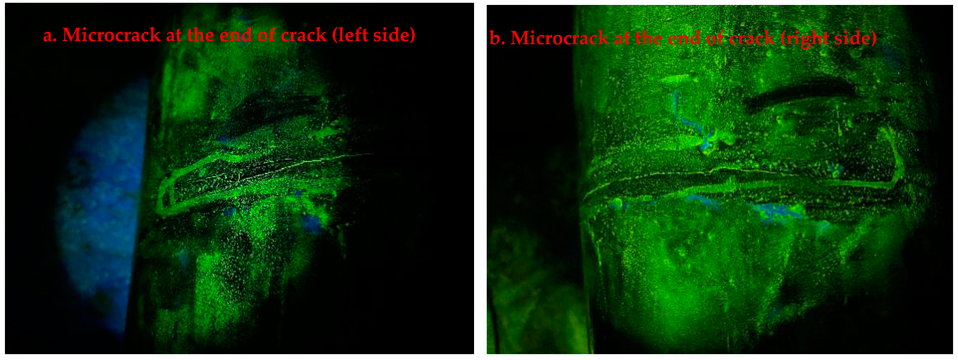
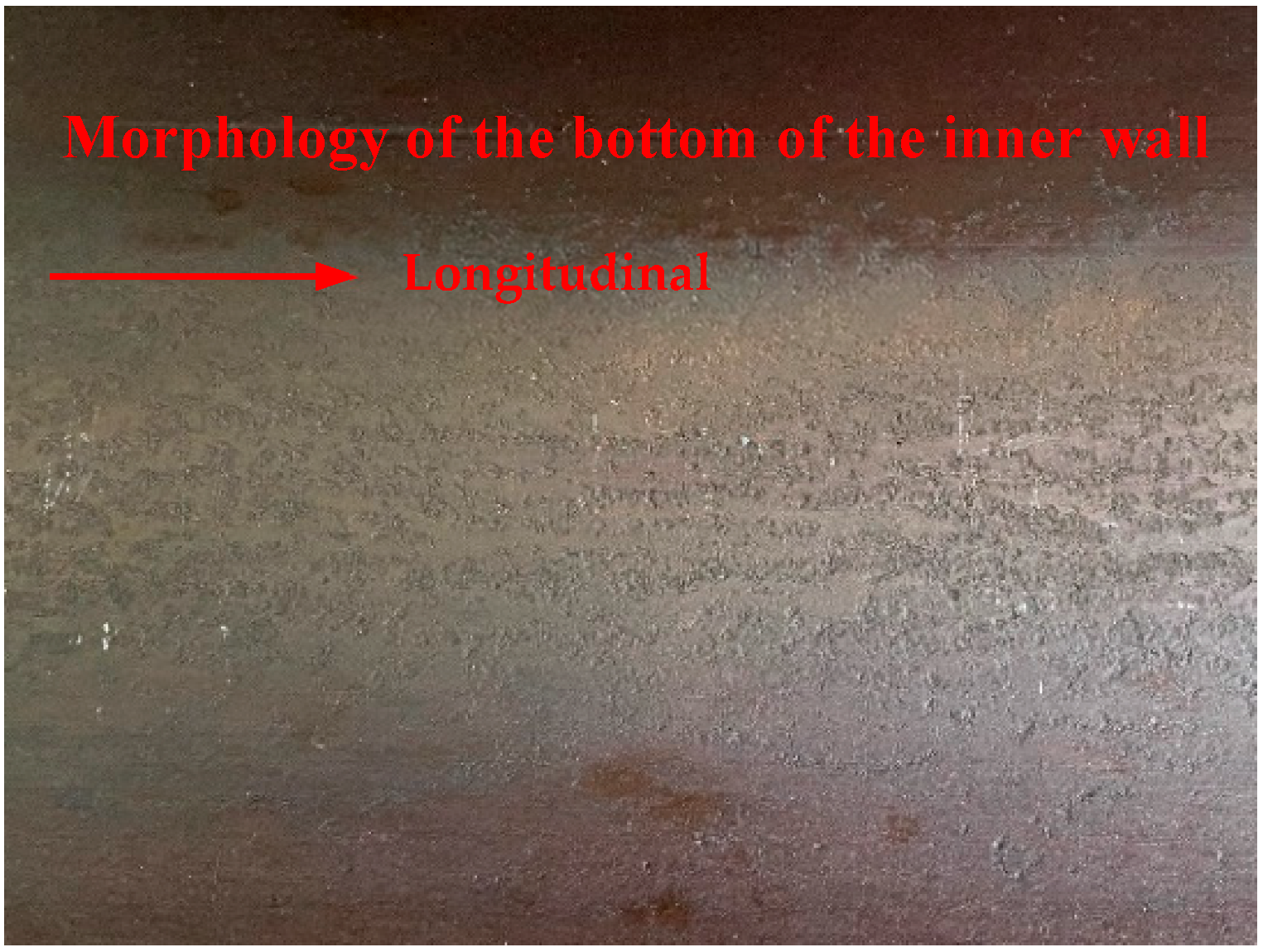
3.1. Non-Destructive Testing

Non-destructive testing was performed on the failed tube body after removing the outer corrosion layer, in accordance with ASTM E709-21 [12]. The test results are shown in Figure 3, revealing that the crack extends along the circumferential direction to both ends with microcrack branching lines at each end. The results indicated that no additional cracks or instances of cracking were detected on the outer wall of the failed tube, apart from the circumferential cracking and crack propagation zone.
The failed tube was dissected to observe the inner wall morphology, as depicted in Figure 4. Fluorescent magnetic particle detection was employed to observe the inner wall, revealing an absence of microcracks at the three, six, and nine o’clock positions along the pipeline circumference. However, circumferential microcracks were clearly evident at the top section of the pipeline, as illustrated in Figure 4 (see inside the red circle). The distribution pattern indicates that microcracks are predominantly concentrated in the area between the eleven o’clock and one o’clock positions in a clockwise direction. So, the existence of microcracks indicates that the pipeline cracking is inevitable. As long as the stress of the pipeline exceeds a certain critical value, the cracking failure will inevitably occur in an acidic environment.
In addition, the morphology of the inner wall illustrates that there were traces of fluid medium deposition at the bottom of the pipe at six o’clock, and small pitted corrosions were observed in the localized deposition area at the bottom (Figure 5). The surfaces on both sides of the inner wall of the tube appear flat, with no apparent signs of corrosion.

3.2. Physical and Chemical Properties

3.2.1. Tensile Properties

The test was carried out using UTM5305 material testing machine (Sansi equipment Co., LTD, China). According to ASTM A370-22 [13], the mechanical properties of the failed tube were tested by sampling the uncracked area. The test results are shown in Table 1. Figure 6 illustrates the macro-morphology of the stretched sample. It was evident that one of the three parallel samples (sampling at the top of the tube) exhibits noticeable original microcracks near the fracture (See the red box 1 in Figure 6). During the tensile test, these original microcracks were pulled apart. At the same time, microcracks were also found in other areas of the inner wall of this sample (see the red boxes 2 and 3 in Figure 6). The sample ultimately fractured at a microcrack and has less pronounced necking compared with the other two samples.
By observing the macro-morphology of the original microcrack in the fracture (see Figure 7c1), it can be seen that the original crack has a certain depth and appears dark brown (see red circle). Scanning electron microscopy was used to observe the cross section and measure the original microcrack. It can be seen that the depth of the original microcrack was 0.755 mm, and the microscopic morphology of the cross section of the fracture is shown in Figure 7c2.

3.2.2. Chemical Composition

The chemical composition of the sample was analyzed in accordance with ASTM A751-21 [15]. The testing was carried out on both the outer and inner surfaces (microcrack area). The test results are presented in Table 2 and meet the requirements for material chemical composition specified in API SPEC 5L.

3.2.3. Charpy Impact Performance

According to the standard ASTM A370-22 [13], the impact performance of the pipe materials was tested, and the test results are presented in Table 3 and meet the requirements of the API SPEC 5L [14] standard.
Concurrently, the micro-hardness of the sample at the top of the pipeline was measured from the outer surface to the inner surface along a designated test line. The hardness values ranged within a specific range (HV134–HV139), indicating that there was no significant difference in hardness between the inner and outer surfaces of the failed pipe.

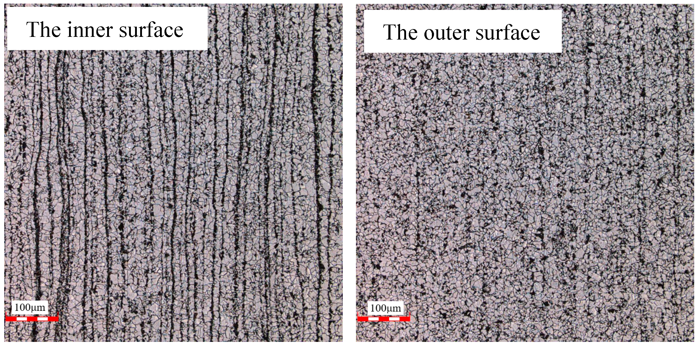
3.2.4. Metallographic Structure and Inclusion

Metallographic samples were extracted from the top (microcrack area) and the bottom two areas of the pipe, respectively. The metallographic structure consisted mainly of pearlite + ferrite. Additionally, compared with the micro-metallographic structure between the inner and the outer surface of the samples at the top and bottom of the pipeline (refer to Figure 8 and Figure 9), it was observed that the microstructure of both the inner and outer surface of the samples was similar. Meanwhile, there were evident segregation phenomena in the metallographic microstructure, and the segregation of the inner surface was relatively obvious. The grain size and non-metallic inclusion of the sample are detailed in Table 4. The results indicate that there was no significant difference in grain size and impurity content between the top and bottom of the pipe, which was not the primary factor influencing the material properties [16].

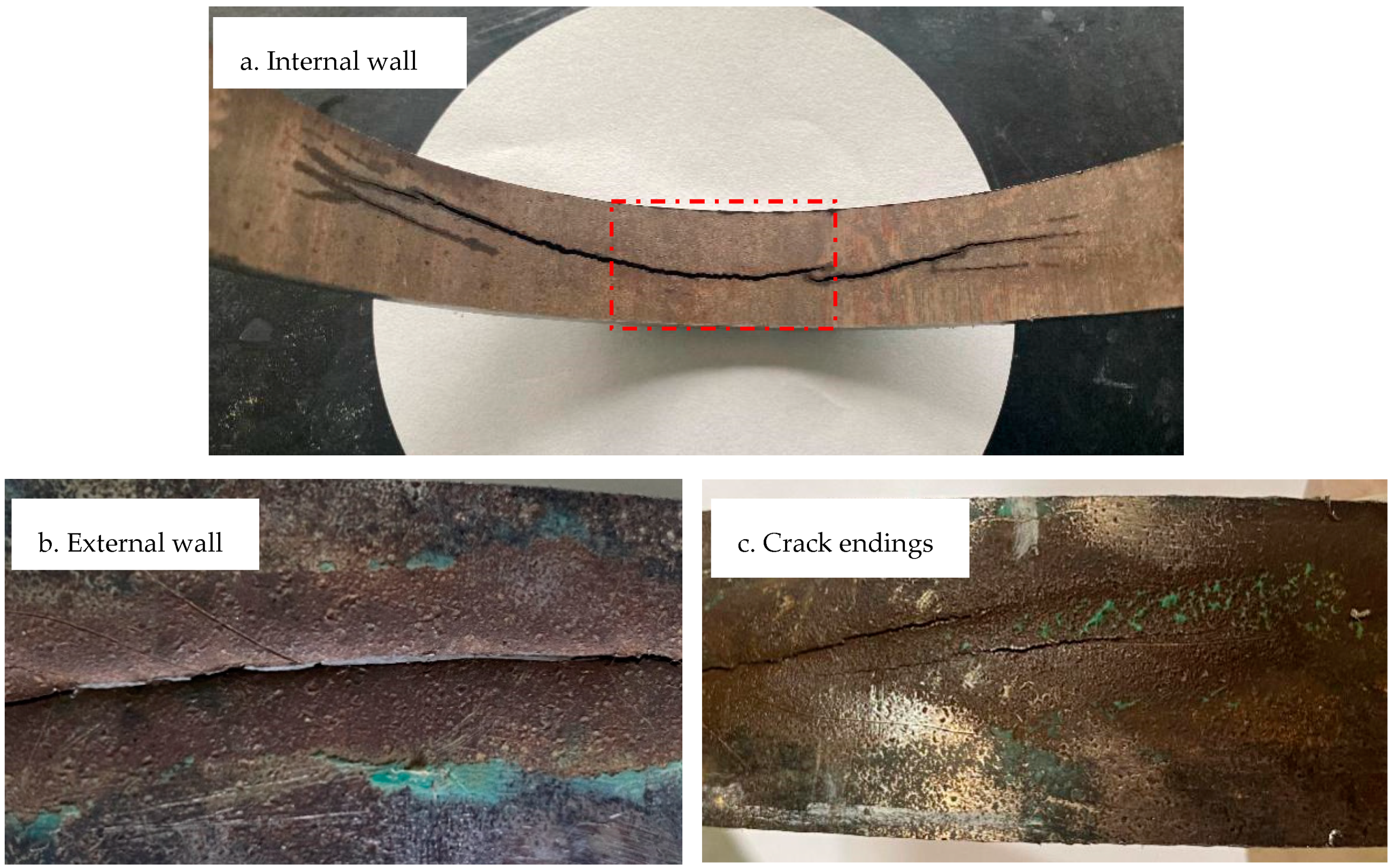
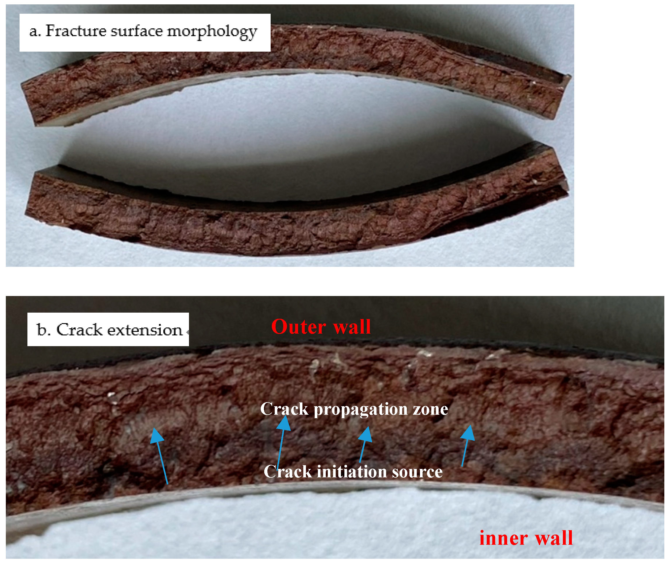
3.3. Failure Fracture Observation

The internal wall morphology of the crack in the failed pipe was observed, as depicted in Figure 10a. It is evident that the main crack was circumferential and extends to both ends, and the dendritic microcracks presented near the ends of the main crack. Figure 10b shows the external wall topography corresponding to the main crack, and it can be seen that the crack penetrated the wall thickness of the pipe, while Figure 10c shows the macroscopic morphology of the end of the main fracture. It is apparent that the cracks also penetrated the wall thickness at this point.
Figure 11 shows the fracture morphology of the main crack in the middle region, which corresponds to the red box area in Figure 10a. The fracture has lost its metallic luster and the surface was covered with dark brown corrosion products. Figure 11b shows the locally enlarged topography of the fracture. It can be inferred from the characteristics of the fracture initiation zone and crack propagation zone that the fracture originated from the internal surface and has multi-source fracture characteristics.

3.4. Metallographic Structure of Fracture

The longitudinal sample containing a cross section was intercepted in the central area of Figure 10a, and the metallographic structure near the fracture was observed, as shown in Figure 12a. Upon examination of the section, it was evident that there was a crack of longitudinal extension, with no abnormal tissue present around it. In Figure 12b, the metallographic structure of the cross section at the crack revealed dendritic expansion characteristics. Meanwhile, the energy spectrum analysis of products from various locations within the crack gap revealed a significant presence of sulfur (Figure 12(b1,b2)). The atomic percentage concentration of sulfur was measured as high as 5.77%, indicating the presence of H2S in the service medium environment.
At the same time, the cross section of the sample in the inner wall microcrack area was examined, as depicted in Figure 13, revealing distinct characteristics of inter-granular and trans-granular crack propagation. The depth of the cracks was measured from the inner surface along the wall thickness direction, with some cracks extending up to 1.15 mm.

3.5. Fracture Microstructure and Corrosion Product Analysis

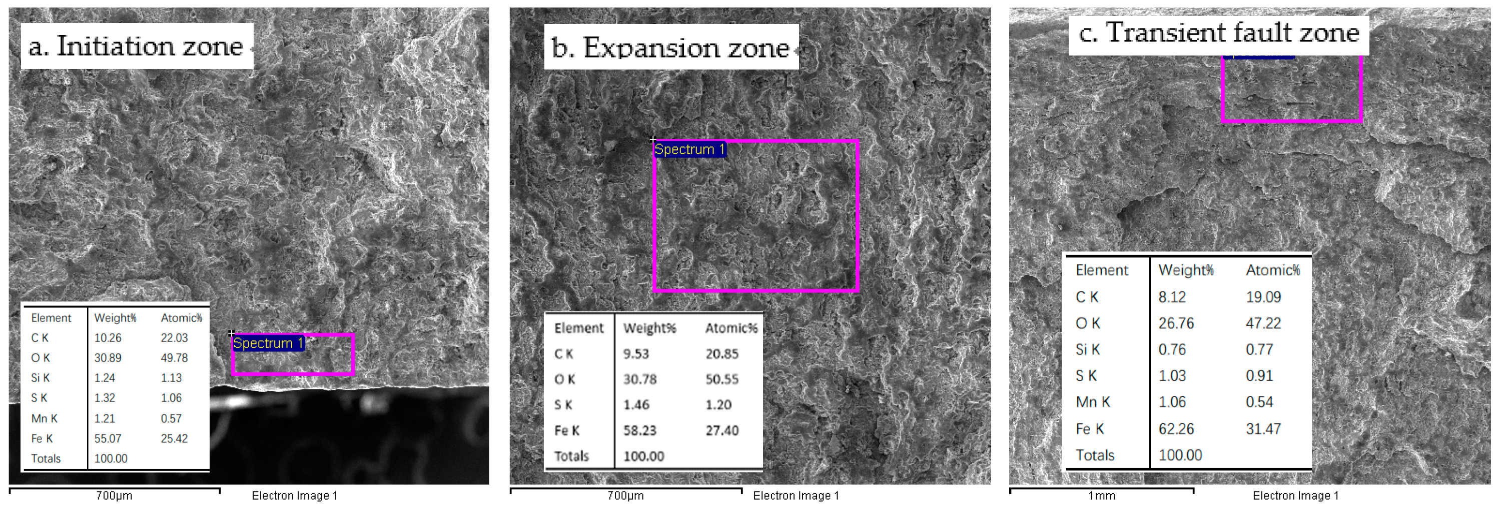
3.5.1. Failure Fracture Analysis

Scanning electron microscopy was utilized to observe the microscopic corrosion morphology of the fracture surface, while EDS was employed for energy spectrum analysis of the corrosion products on the surface of the cracking source region, crack propagation region, and transient fault region, as depicted in Figure 14a–c. It was evident that the primary elements present were C, O, S, and Fe. Among these elements, S was detected from the initiation zone to the transient fault zone with a sulfur atom content ranging from 0.91% to 1.2%. This indicates that H2S reacts with the matrix surface along the direction of crack propagation after crack formation.

3.5.2. Fracture Analysis of Tensile Sample

The fracture morphology of the mechanical samples at the microcrack were observed (as shown in Figure 15a). It can be seen that the surface of the original microcrack on the cross section was dark brown because of corrosion. By observing the crack initiation source region of the microcrack, it can be seen that the radial quasi-cleavage fracture characteristics were obvious, accompanied by secondary cracks (as shown in Figure 15b).

3.5.3. XRD Analysis of Corrosion Products on Fracture Surface

The corrosion products were sampled from the cracked surface of the microcrack for XRD phase analysis. The results indicated that the corrosion products mainly consisted of a mixture of FeS, Fe3O4, and Fe(OH)3 (refer to Figure 16). When H2S dissolves in water, its ionization occurs as follows:
H2S H+ + HS
HS H+ + S2−
Then, the anion (HS) dissociates further to S2− and H+. Therefore, the S2− ion reacts with iron to form the black FeS corrosion product in the service environment [17,18].

4. Comprehensive Analysis

According to the API SPEC 5L [14] standard for pipelines, the results of tensile strength, impact performance, and chemical composition meet the standard requirements. The metallographic structure of the material consists of pearlite and ferrite.
Magnetic particle detection was conducted on the outer surface of the failed tube, revealing no others cracks except for the failure crack. However, the fluorescent magnetic particle detection on the inner wall revealed that there were relatively many and short microcracks (6–10 mm) between one and eleven o’clock at the top of the pipe. A longitudinal section of the microcrack area was examined for metallographic observation, which showed that the crack extended approximately 1.15 mm along the wall thickness direction. Based on the characteristics of the corrosion products at tensile fracture, it was believed that these microcracks formed in the service environment. The microstructure analysis indicated no difference between the top region (with microcracks) and bottom region of the pipe, both exhibiting a grade 3 ribbon structure. This shows that the ribbon structure was not an influential factor for pipeline cracking.
The macroscopic morphology analysis of the fracture revealed that the fracture initiated on the inner wall of the pipe and extended along the wall thickness to the outer wall until fracture, resulting in a multi-source brittle fracture morphology. The circumferential fracture exhibited more dendritic bifurcation at its end, and the crack propagation displayed obvious inter-granular and trans-granular brittle characteristics, which were consistent with stress corrosion cracking [19,20]. The initial depth of the microcrack at the top of the pipeline was 0.755 mm, and the micro-morphology of the crack surface exhibited quasi-cleavage with accompanying secondary cracks, indicating a brittle fracture [21,22].
Corrosion products extracted from the main crack surface, inside the longitudinal crack, and within the top microcrack all showed varying percentages of the element S (ranging from 1.20% to 5.77%). Furthermore, XRD phase analysis revealed FeS components in the corrosion products within the crack, suggesting that there was a certain amount of H2S present in the medium surrounding the pipe; this also confirmed reports of a faint H2S odor by operators. Additionally, numerous circumferential microcracks were observed at the top of the pipe, further supporting evidence for inevitable circumferential fractures along its length. It was inferred that there existed localized tensile stress in this region.
Combined with the analysis of the service environment, H2S dissolved in water and ionized into H+ in the wet environment, which acts as a depolarizing agent to promote electron loss in the matrix. Simultaneously, H+ undergoes a reduction reaction on the matrix surface to form H atoms that enter the metal matrix and creates high hydrogen pressure at pipe defects, independently or cooperatively causing the nucleation and expansion of hydrogen-induced cracks. Furthermore, the bonding force between metal atoms weakens, reducing external stress required for crack propagation and increasing material cracking sensitivity. Therefore, under the action of external stress or residual stress of the weld at both ends of the pipeline, the pipeline was most prone to cracking and damage at weak points [23,24,25]. Based on the above analysis, it was concluded that the pipeline fracture was caused by sulfide stress corrosion cracking.
The gathering and transportation pipeline was buried underground, with a seamless construction. Therefore, it is uncertain whether the local formation collapse or the welding stress at both ends of the pipe leads to local tensile stress in the pipe body. It is recommended to assess the operational status of the pipeline based on actual working conditions on-site. It is also crucial to identify the source of H2S, whether it is present in the transport medium or originates from sulfate-reducing bacteria. This is particularly critical for ensuring the safe operation of the entire gathering pipeline.

5. Conclusions and Suggestions

(1)
The mechanical properties of the pipeline met the relevant standards;
(2)
The cause of the pipeline fracture was sulfide stress corrosion cracking;
(3)
It is recommended to identify the source of H2S, confirm whether the transport medium was contaminated with H2S or sulfate-reducing bacteria by-products, and assess potential cracking risks in other sections of the same pipeline;
(4)
It is advisable to investigate stress issues and pay special attention to critical areas, such as girth welds connecting the pipes;
(5)
Strict control over the composition of the conveying medium is advised to prevent H2S contamination. Continuous monitoring of anti-corrosion measures should be carried out to prevent bacterial corrosion. Quality control over pipelines, especially residual stresses at welds, should be strictly enforced. Regular non-destructive testing on pipelines is recommended to mitigate and delay pipeline failures.

Author Contributions

Methodology, Z.Z. and Y.H.; Formal analysis, J.Y.; Investigation, X.Z. and J.Y.; Resources, Y.H.; Data curation, Z.Z. and Z.H.; Writing—original draft, X.Z.; Writing—review & editing, X.Z.; Project administration, Z.H. All authors have read and agreed to the published version of the manuscript.

Funding

This research was funded by CNPC Science and Technology Project, grant number 2023ZZ11-02, the China National Petroleum Corporation for Science Research, and the Technology Development Project (2021ZZ01-04).

Institutional Review Board Statement

Not applicable.

Informed Consent Statement

Not applicable.

Data Availability Statement

Data are contained within the article.

Conflicts of Interest

Author Zicheng Zhang was employed by the company Logging&Testing Services Company of Daqing Oilfield; Author Zhiwu He was employed by the company Oil and Gas Technology Institute of Changqing Oilfield. The remaining authors declare that the research was conducted in the absence of any commercial or financial relationships that could be construed as a potential conflict of interest.

References

  1. Wu, M.; Xie, F.; Chen, X.; Wang, D.; Sun, D.-X. Research progress and thinking on corrosion failure of buried oil and gas pipelines. Pet. Storage Transp. 2022, 41, 712–722. [Google Scholar]
  2. Rao, B.-Y.; Wang, C.-P.; Feng, X.-Z.; Yang, X.-L.; Lv, X.-M.; Liu, M.-M. Analysis on Corrosion Failure of Producing Pipe in an Oilfield. Mater. Prot. 2020, 53, 135–138. [Google Scholar]
  3. Fan, H.-Y.; Jiang, Z.-Q.; An, X.-W.; Han, S.-P. Cause Analysis of Stress Corrosion Fracture of Oilfield Pipeline. Oil-Gasfield Surf. Eng. 2022, 41, 71–74. [Google Scholar]
  4. Zhang, J.-J.; Zhao, W.; Zhang, X. Understanding of Corrosion Failure Regularities of Buried Pipelines and Countermeasures. Oil-Gasfield Surf. Eng. 2022, 41, 61–67. [Google Scholar]
  5. Song, L.-F.; Liu, Z.-Y.; Lu, L.; Li, X.-J.; Sun, B.-Z.; Cheng, H.-L. A failure case of P110 steel tubing in CO2 flooding well. Anti Corros. Methods Mater. 2020, 67, 453–463. [Google Scholar] [CrossRef]
  6. Chen, D. Bended pipe cracking reason of gathering pipeline in Tahe Oilfield. Oil Gas Storage Transp. 2022, 30, 396–399. [Google Scholar]
  7. Xiong, G.; Wu, W.; Ji, W. Failure analysis of sour natural gathering and transportation pipeline. Chem. Oil Gas 2012, 41, 99–101. [Google Scholar]
  8. Chen, L.; Yu, H.; Zhang, H.; Fan, X.; Gu, F.; Ji, Y. Corrosion failure Causes of surface oil pipe in an overseas high-sulfur and high-salt oilfield. Corros. Prot. 2021, 42, 73–77. [Google Scholar]
  9. Kane, R.D.; Maldonado, J.G.; Moore, P.W. Full Scale Testing of Pipe Containing Surface Imperfections in H2S and non-H2S Environment. In Proceedings of the Corrosion 2016, San Diego, CA, USA, 12–16 March 2006. [Google Scholar]
  10. Cernocky, P.; Paslay, P.; Livesay, R. Probabilistic Approach to Pipe Crack Initiation Failure and Crack Propagation Failure in H2S Environments. In Proceedings of the Corrosion 2010, San Antonio, TX, USA, 14–18 March 2010. [Google Scholar]
  11. Zhang, M.; Chu, Q.-L.; Li, J.-H.; Wu, W.; Fan, W.; Luo, H.; Zhi, J.; Hui, Y. Failure analysis of a welded impeller in coke oven gas environment. Eng. Fail. Anal. 2014, 38, 16–24. [Google Scholar] [CrossRef]
  12. ASTM E709-21; Standard Guide for Magnetic Particle Testing. ASTM: West Conshohocken, PA, USA, 2021.
  13. ASTM A370-22; Methods and Definitions for Mechanical Properties Testing of Steel Products. ASTM: West Conshohocken, PA, USA, 2022.
  14. API SPEC 5L; Line Pipe. API: Washington, DC, USA, 2018.
  15. ASTM A751-21; Determination of Multi-Element Content of Carbon Steel and Medium and Low Alloy Steel by Spark Discharge Atomic Emission Spectrometry (Conventional Method). ASTM: West Conshohocken, PA, USA, 2021.
  16. Khan, W.A.; Hayat, Q.; Ahmed, F.; Ali, M.; Zain-ul-Abdein, M. Comparative Assessment of Mechanical Properties and Fatigue Life of Conventional and Multistep Rolled Forged Connecting Rods of High Strength AISI/SAE 4140 Steel. Metals 2023, 13, 1035. [Google Scholar] [CrossRef]
  17. Nyborg, R.; Dugstad, A. Top of Line Corrosion with High CO2 and Traces of H2S. In Proceedings of the Corrosion 2009, Atlanta, GA, USA, 22–26 March 2009. [Google Scholar]
  18. Albiter, A. Sulfide Stress Cracking Assessment of Carbon Steel Welding with High Content of H2S and CO2 at High Temperature: A Case Study. Engineering 2020, 12, 863–885. [Google Scholar] [CrossRef]
  19. Lee, G.; Park, K.J.; Bae, D.H. Assessment of the sulfide stress corrosion cracking characteristics in the multi-pass weld of the A106 Gr B steel pipe. J. Mech. Sci. Technol. 2009, 23, 1244–1249. [Google Scholar] [CrossRef]
  20. Lu, C.-H.; Liu, Y.-G.; Wang, X.-H.; Li, F.-P.; Qu, T.-T. Failure Analysis of Fractured S135 Grade Drill Pipe. Appl. Mech. Mater. 2013, 43, 69–74. [Google Scholar] [CrossRef]
  21. Xu, S.-G.; Huang, S.-J.; Guo, D.-G.; Zhao, Y.-J.; Song, M.-D. Failure analysis of a carbon steel pipeline exposed to wet hydrogen sulfide environment. Eng. Fail. Anal. 2017, 71, 1–10. [Google Scholar] [CrossRef]
  22. Li, X.-H.; Liu, C.-X.; He, B.; Lv, C.-T.; Gao, Z.-M.; Liu, Y.-C. Analysis of cracks origin behaviors during sulfide stress corrosion (SSC) in HSLA steel at different temperatures by electrochemical noise. J. Iron Steel Res. Int. 2022, 29, 1836–1845. [Google Scholar] [CrossRef]
  23. Luo, S.; Liu, M.; Shen, Y.; Lin, X. Sulfide Stress Corrosion Cracking Behavior of G105 and S135 High-Strength Drill Pipe Steels in H2S Environment. J. Mater. Eng. Perform. 2019, 28, 1707–1718. [Google Scholar] [CrossRef]
  24. Neshati, J.; Saremi, M.; Mashhadi, G. A new approach in top-of-line corrosion studies in CO2/H2S environment. Corros. Eng. Sci. Technol. 2023, 58, 723–733. [Google Scholar] [CrossRef]
  25. Zhao, X.-H.; Feng, Y.-R.; Yin, C.-X.; Han, Y. Corrosion Behavior of Tubing Steel 15Cr in Artificial Formation Water Solutions Containing CO2/H2S. Corros. Sci. Prot. Technol. 2016, 28, 325–331. [Google Scholar]
Figure 1. Photo of the pipeline failure site.
Coatings 14 00770 g001
Figure 2. Macroscopic morphology of the outer wall of the failure sample.
Coatings 14 00770 g002
Figure 3. Non-destructive testing appearance of the outer wall.
Coatings 14 00770 g003
Figure 4. Magnetic particle test results on the top of the inner wall.
Coatings 14 00770 g004
Figure 5. Macroscopic corrosion morphology of the inner wall.
Coatings 14 00770 g005
Figure 6. Fracture morphology of the tensile test.
Coatings 14 00770 g006
Figure 7. Fracture morphology of the tensile fracture sample.
Coatings 14 00770 g007
Figure 8. Inner and outer surface metallographic structures of the sample at the top of the tube.
Coatings 14 00770 g008
Figure 9. Inner and outer surface metallographic structures of the sample at the bottom of the tube.
Coatings 14 00770 g009
Figure 10. Macrocrack appearance in the failure tube.
Coatings 14 00770 g010
Figure 11. Fracture morphology of the circumferential main crack.
Coatings 14 00770 g011
Figure 12. Metallographic structure and EDS analysis near the fracture. (a) Metallographic structure of longitudinal sections; (b) morphology of crack growth; (b1) Energy spectrum analysis of products in the blue circle region; (b2) Energy spectrum analysis of products in the red ring region.
Coatings 14 00770 g012
Figure 13. Crack observation on the inner surface of the sample at the top of the pipeline.
Coatings 14 00770 g013
Figure 14. Fracture surface corrosion morphology and energy spectrum analysis.
Coatings 14 00770 g014
Figure 15. Cleavage fracture morphology of the tensile sample at the microcrack surface.
Coatings 14 00770 g015
Figure 16. XRD analysis of the corrosion products on the fracture surface.
Coatings 14 00770 g016
Table 1. Mechanical properties of the failed tube sample.
ResultsTensile Strength
Rm (MPa)
Yield Strength
Rt 0.5 (MPa)
Elongation after Breaking
A (%)
Materials
L360N538, 533, 519404, 397, 39140, 33, 22
API SPEC 5L [14]460–760360–530 ≥21.3
Table 2. Test results of the chemical composition of the sample (Wt.%).
ElementCSiMnPSVTiNb
1#L360N0.120.381.420.01260.0050.00460.0240.039
2#L360N0.140.391.400.0120.00540.00460.0240.036
API SPEC 5L [14]≤0.24≤0.45≤1.40≤0.025≤0.015≤0.10≤0.04≤0.05
Remark: 1#: surface area outside the tube; 2#: the surface of the tube body contains microcracks; 3#: according to API SPEC 5L, the relationship between C content and Mn content is limited, and the detection results of the element Mn meet the standard requirements.
Table 3. Test results of the impact performance.
ResultsSample Size (mm) Notch ShapeTest Temperature (°C)Shock Absorption Energy (J)
Materials
L360N5 × 10 × 55V0113, 118, 95
API SPEC 5L [14]5 × 10 × 55//≥13.5
Table 4. Results of metallographic analysis of the tube samples.
NumberNon-Metallic InclusionGrain SizeRibbon Structure
ABCD
ThinThickThinThickThinThickThinThick
Top sample0.500.50000.509.0 3.0
Bottom
sample
0.500.50000.509.5 3.0
Note: A: sulfides; B: alumina; C: silicate; D: spherical oxides.
Disclaimer/Publisher’s Note: The statements, opinions and data contained in all publications are solely those of the individual author(s) and contributor(s) and not of MDPI and/or the editor(s). MDPI and/or the editor(s) disclaim responsibility for any injury to people or property resulting from any ideas, methods, instructions or products referred to in the content.

