Review

Plasma-Sprayed Osseoconductive Hydroxylapatite Coatings for Endoprosthetic Hip Implants: Phase Composition, Microstructure, Properties, and Biomedical Functions

by
Robert B. Heimann
Am Stadtpark 2A, D-02826 Görlitz, Germany
Coatings 2024, 14(7), 787; https://doi.org/10.3390/coatings14070787
Submission received: 18 May 2024 / Revised: 19 June 2024 / Accepted: 20 June 2024 / Published: 24 June 2024
(This article belongs to the Special Issue Advanced Biomaterials and Coatings)

Abstract

:
This contribution attempts to provide a state-of-the-art account of the physicochemical and biomedical properties of the plasma-sprayed hydroxylapatite (HAp) coatings that are routinely applied to the surfaces of metallic endoprosthetic and dental root implants designed to replace or restore the lost functions of diseased or damaged tissues of the human body. Even though the residence time of powder particles of HAp in the plasma jet is extremely short, the high temperature applied induces compositional and structural changes in the precursor HAp that severely affect its chemical and physical properties and in turn its biomedical performance. These changes are based on the incongruent melting behavior of HAp and can be traced, among many other analytical techniques, by high resolution synchrotron X-ray diffraction, vibrational (Raman) spectroscopy, and nuclear magnetic resonance (NMR) spectroscopy. In vivo reactions of the plasma-sprayed coatings to extracellular fluid (ECF) can be assessed and predicted by in vitro testing using simulated body fluids (SBFs) as proxy agents. Ways to safeguard the appropriate biological performance of HAp coatings in long-term service by controlling their phase content, porosity, surface roughness, residual stress distribution, and adhesion to the implant surface are being discussed.

1. Introduction

There is a growing demand for safe, high performance, and increasingly sophisticated medical implants, because our society is moving toward an increasingly aging population. Presently, much research is focused on advanced medical implants that are not only biocompatible but have modified surfaces able to direct specific immunomodulation at the cellular level. An important surface modification tool is the deposition by plasma spraying of hydroxylapatite (HAp) coatings, which promote improved implant performance and longevity, effectively counteract foreign body reaction by avoiding the formation of an acellular fibrous capsule, and provide by their osseoconductive nature enhanced bone cell adhesion, migration, spreading, and proliferation.
Total hip (THA) and knee arthroplasty (TKA) are among the most frequently performed and in their long-term outcome highly successful and effective surgical interventions worldwide. The need for endoprosthetic hip and knee implants is deeply rooted in the kinematics of human locomotion. The forces acting on the knee and hip joints can be expressed by multiples of body mass. They are approximately one times the body mass while resting (~1 kN), up to three times during walking, up to five times during running, and up to eight times when jumping. The risk of serious joint damage increases dramatically beyond this threshold. Intensifying the socio-economic impact of this physiologically given situation is the fact that people generally live longer and gain weight by overeating, excessive consumption of sugar, fat, and alcohol, and a sedentary lifestyle. Eventually, the cartilage tissue lining the articulating parts of the joints wears away. This leads to increased friction during movement, and in turn to inflammation, pain and, finally, immobilization. Common root causes for the need of hip joint replacement are osteoarthritis, rheumatoid arthritis, osteonecrosis, injuries or broken bones from trauma or disease, and degeneration due to wear and tear. In all these cases, a THA (total hip arthroplasty) is the only reasonable option to restore mobility and hence, to promote a rewarding life without pain. This type of operation has a long pedigree, starting with the pioneering work by Themistocles Gluck (1853–1942) and continuing with Robert Judet (1909–1980) and Austin T. Moore (1899–1962) and then on to Sir John Charnley (1911–1982), who designed the hip joint replacement system on which all subsequent solutions are based.
In 2022, some 3.1 million THA and TKA procedures were reported in the USA alone, among them 37% primary THA and 54% primary TKA, the remainder being revision operations [1]. In 2021, ceramic-on-polyethylene (CoP) bearing couples were, at about 63%, the dominant choice for THA. Cementless fixation of the femoral stem constituted about 95% of all THA, in contrast to only 19% of all TKA.
In Germany, about 178,000 primary THA and 137,000 primary TKA were registered in 2022. Fifty-eight percent of all these THAs were performed with a ceramic-on-polyethylene (CoP) sliding couple [2]. Most other remaining implants used a metal-on-polyethylene (MoP) combination. Some 10% of all hip operation surgeries were revisions, the causes of which were, in descending order, implant loosening (23%), periprosthetic infection (16%), post-operative periprosthetic fracture (16%), dislocation (14%), wear (6%), and others (24%). Purely mechanical implant failure was remarkably low; it was reported in only 2% of all THA revision operations, attesting to the high reliability and solidly entrenched quality standards of modern biomedical devices and operation techniques. Indeed, the revision probability after 5 years was found to be only around 4%. In a global context, in Switzerland, Germany, and Austria, the number of THAs performed were a high 3230/1 million population (ppm), 3010 ppm, and 2870 ppm, respectively, compared to only 400 ppm in Chile, 180 in Costa Rica, and a paltry 70 ppm in Mexico. In 2021, the THA average of all OECD countries was 1720 ppm [2].
The high incidence of THA and TKA operations in the developed and increasingly, in the developing world, is reflected in the global hip replacement implant market valued at USD 7.26 billion in 2022, expected to grow at a CAGR of 5.2% to USD 11.5 billion in 2031 [3]. Hence, hip and knee arthroplasties constitute a meaningful part of the global GNP. This is also mirrored by the growing amount of research and development effort designed to improve existing and discover novel solutions to the problem of the growing demand for endoprosthetic devices. Several aspects of this research activity will be discussed in this contribution. It is this continuously accelerating research effort that makes the present review needed, timely, and meaningful.

2. Why Hydroxylapatite Coatings?

Figure 1A shows a high-end THA implant that consists of a titanium alloy stem with an alumina femoral ball attached. The stem will be anchored in the femur, and an acetabular cup with an alumina inset anchored in the hip bone. During the absence of synovial fluid that lubricates the joints, this type of ceramic-on-ceramic (CoC) bearing couple is highly effective and reliable, even though it may produce a disturbing squeaking noise during walking and a high risk of fracture [4]. In addition, its comparatively high cost puts a severe strain on the healthcare systems of many countries. Hence, for economic reason, the standard endoprosthesis does not use the bearing couple option shown in Figure 1A but that of a ceramic (CoP) or metal (MoP) femoral head articulating against a highly cross-linked polyethylene-lined acetabular cup. Figure 1B shows the cross-sectional image of the implant-bone interface, demonstrating that a plasma-sprayed hydroxylapatite (HAp) layer provides a tight and continuous connection between an implant and bone [5].
As shown in Figure 1A, modern endoprosthetic implants are frequently coated with a thin layer of hydroxylapatite (HAp) that assists in tight and continuous osseointegration (Figure 1B). At present, a cementless implant coated with HAp is regarded as the ‘gold standard’ in orthopedics and dentistry. The reason for this is grounded in the chemical and structural similarity of synthetic HAp with biological, i.e., bone-like apatite (bone mineral), making HAp a highly biocompatible material. Nevertheless, although synthetic HAp noticeably differs in its chemical make-up, stoichiometry, crystallinity, defect density, presence of hydroxyl ions, and type and degree of ion substitution from bone mineral, in biomedical applications it spans a wide range from hip and dental root implant coatings and porous bone-growth supporting 3D-printed scaffolds to bone cavity filling material and drug and gene delivery vehicles.
Any foreign material or device incorporated into the body triggers a host/recipient response that manifests itself in the five time-dependent foreign body reaction (FBR) phases, i.e., (i) blood protein adsorption completed a few seconds after contact, (ii) neutrophil recruitment and associated acute inflammation within minutes, (iii) monocyte recruitment and their differentiation to macrophages, associated with chronic inflammation within hours, (iv) foreign body multinucleated giant cell formation after some days, and (v) fibrotic encapsulation within weeks. Fibrotic encapsulation is a protective measure of the body, but unfortunately, it prevents solid and lasting osseointegration of the implant (Figure 2A).
The fibrous encapsulation of the implanted device can affect the implant’s function and frequently leads to failure. For example, interface loosening of a press-fitted implant may be caused by mechanically induced periprosthetic osteolysis, in particular when associated with micro-movements of the patient during the healing phase, which limits implant longevity. Such early loosening is best defined as prosthetic migration. Initiation of loosening during or shortly after surgery is promoted by poor implant interlock, poor bone quality, and osteolytic resorption of a necrotic bone bed.
The quest for reducing the FBR is an effective way to promote better implant performance and longevity, including enhanced adhesion and strengthening of the implant-bone interface. Among many possible ways to combat FBR [7], coating the implant stem and the casing of the acetabular cup of a hip joint implant with a thin layer of osseoconductive HAp (Figure 1A and Figure 2B) is an economically viable and biomedically reliable route toward alleviating the FBR and thus preventing the formation of a fibrous connective tissue capsule. Recast in simple terms, an HAp coating acts as an agent of biological subterfuge, triggering the body into accepting the implant as part of its own metabolic environment, thus avoiding the negative consequences of FBR.
In addition to preventing the formation of a fibrous acellular connective tissue capsule surrounding the implant, other advantages of a plasma-sprayed HAp coating include:
  • Enhanced bone apposition rate by osseoinduction, owing to preferential adsorption of bone growth-supporting factors such as BMPs as well as NCPs such as osteocalcin, osteopontin, sialylated glycoproteins, proteoglycans, and several other hormones, chemokines and cytokines;
  • Enhanced bone-bonding ability that provides a strong and continuous interface between bone tissue and implant and thus enables the transmission of compressive as well as (limited) tensile and also some shear forces;
  • Variable HAp coating thicknesses between 50 and 250 µm can be selected, dependent on medical requirements;
  • The option to apply some novel deposition techniques including SPS and SPPS allows the deposition of coatings with thicknesses << 50 µm;
  • Acceleration of the healing process when compared to implants without an osseoconductive coating;
  • Supporting attachment of the epithelium in the case of transmucosal dental implants;
  • Reducing the health risk of potentially toxic heavy metal ions released from the surface of the metallic implant into the periprosthetic tissue and thus minimizing a possible cytotoxic response, and
  • Support available by quality control and standards according to ASTM F1185-03 (2014), ASTM F1044-05 (2017), ASTM F1160 (2014), ISO 13179-2: 2018, and others.
However, despite the fact that modern endoprosthetic hip joint implants have reached a high degree of mechanical resilience, chemical inertness, biocompatibility, and overall performance reliability as is manifest in a high Weibull modulus, safeguarding their long-term successful behavior in the aggressive environment of the human body remains a major challenge. Stability problems may be associated with so-called aseptic loosening long after surgery, which to some degree can be related to the large gradient of the modulus of the metallic implant (around 110 GPa for Ti6Al4V) and cortical bone (10–15 GPa). Mechanical loads will then be transmitted through the high modulus metal implant rather than through bone matter, causing the latter to atrophy by forced bone mass loss, because bony health depends strongly on continuous tensile loading and bone remodeling along Wolff’s law. This mechanism is known by the term of ‘stress shielding’. Modern ß-type Ti alloys with elastic moduli closer to that of bone, such as Ti29Nb13Ta4.6Zr (TNTZ), which has a modulus of < 60 GPa, are thought to reduce the risk of stress shielding.
In parallel, the very process of plasma spraying triggers large tensile quenching and thermal stresses at the interface and throughout the bulk coating that in subsequent medical service may result in chipping and even delamination of the osseoconductive HAp coating layer. The reason underlying residual stresses are manifold, but all of them are related to differences in the coefficients of thermal expansion between the metallic substrate and the ceramic coating (see Section 5.3.8).
A possible way to avoid this is to apply bond coats that act as intermediates, binding both the implant and HAp coatings tightly to cortical bone matter [8]. In addition, ceramic bond coats are thought to function as thermal barriers, able to reduce the steep gradient of the coefficient of thermal expansion between metallic implant and ceramic coating. They decrease the rate of heat transfer and thus the degree of thermal decomposition of HAp during plasma spraying, which helps to reduce the occurrence of amorphous calcium phosphate (ACP) formed by a quenching contact at the immediate coating–substrate interface. In addition, a bond coat prevents direct contact between the metallic implant surface and the HAp layer, reducing the risk of thermal decomposition of the HAp, which is known to be catalyzed by metal ions.
However, despite their clear advantages, in the clinical praxis no bond coat of any nature has been applied to endoprosthetic implants yet, even though the ISO 13779-2:2018 norm refers to dual coatings (with the caveat that the testing methods recommended for single HAp coatings cannot be applied to dual layer coatings). Consequently, to date, the biomedical potential of bond coats, although promising, has only been experimentally tested and assessed in animal models [5,6].
Justification for applying biocompatible bond coats can be found in the fact that owing to the chemical and structural similarity of HAp to the inorganic component of living bone (bone mineral), the bonding between HAp and bone matter is much tighter than that between HAp and the metallic implant. A suitable bond coat is designed to overcome this impediment by providing a strong gap bridging potential, conducive to forming three undisturbed and continuous interfaces: bone-HAp, HAp-bond coat, and bond coat-implant metal. Such bond coats are only at the beginning of their complex and involved development cycle. Hence, reliable data on their long-term mechanical, chemical, and biological stability, their compatibility with implants of titanium alloy, CoCrMo alloy, and austenitic stainless steel, and their effect on bone cell adhesion, spreading, and proliferation are still absent and thus need to be collected and assessed by future research. Preliminary animal studies using sheep and dog models [5,6] have shown that titania-based bond coats may be well suited to withstand the high local tensile and shear stresses occurring during micromovement of the animal patient during the first stages of the healing process after implantation.

3. A Short History of Calcium Orthophosphate Research

The close association of calcium phosphates with living matter such as bone has been known for a rather long time. Calcium orthophosphates including hydroxylapatite, Ca10(PO4)6(OH)2, have been known to be associated with organic tissue, more specifically with bone, for at least 250 years [9]. Early evidence points to 1769, when the Swedish chemists Johan Gottlieb Gahn (1745–1818) and Carl Wilhelm Scheele (1742–1786) found tricalcium orthophosphate, Ca3(PO4)2 to be the product of burning bone.
Subsequently, the roles that calcium orthophosphates play in bone, teeth, and pathologic urinary and renal calculi were in part already known by the early 1800s. Some calcium phosphate phases involved in biomineralization, such as amorphous calcium phosphate, octacalcium phosphate, and dicalcium phosphate dihydrate (brushite) [10] were already known or suggested by the end of the nineteenth century.
However, only the application of X-rays to crystal structure analysis over one hundred years ago [11] allowed a paradigmatic shift from a descriptive to a predictive acquisition of information on the structural chemistry of biological calcium phosphates [12,13,14,15,16]. Willem F. de Jong [17] identified the crystal structure of bone calcium phosphate as comparable to geological apatite. Hendricks et al. [12] concluded (erroneously) that the inorganic constituent of bone contains carbonate apatite, Ca10[CO3(PO4)6]⋅H2O, which they thought to be structurally akin to fluorapatite. The same authors mentioned oxyapatite, Ca10O(PO4)6, as an anhydrous product of heating HAp up to 900C. This was disputed by Bredig and coworkers [16], who instead proposed the existence of only partly dehydroxylated oxyhydroxylapatite (OHAp), Ca10(PO4)6X2mOn (X = OH; m + n = 1). In their opinion, an empty X site would destabilize the structure, a contention that was confirmed much later by computer modeling applied to investigate the dehydration of HAp to oxyapatite (OAp) and the defect chemistry of calcium-deficient HAp [18]. However, despite these thermodynamically based constraints, there is evidence that under certain experimental conditions, OAp can be stabilized [19,20,21,22] (see Section 5.3.5).
A thorough account of the composition and crystal structure of Ca-deficient HAp with the approximate formula of Ca10−x(HPO4)x(PO4)6−x (OH, O, Cl, F, CO3, □)2−x∙nH2O; 0 < x < 1; n = 0–2.5 [23,24] was given in a review by Rey et al. [25]. The role water molecules play in the development and structure of bone mineral was emphasized by Pasteris [26]. More details on the structure and biological function of biological apatite can be extracted from Ref. [8].

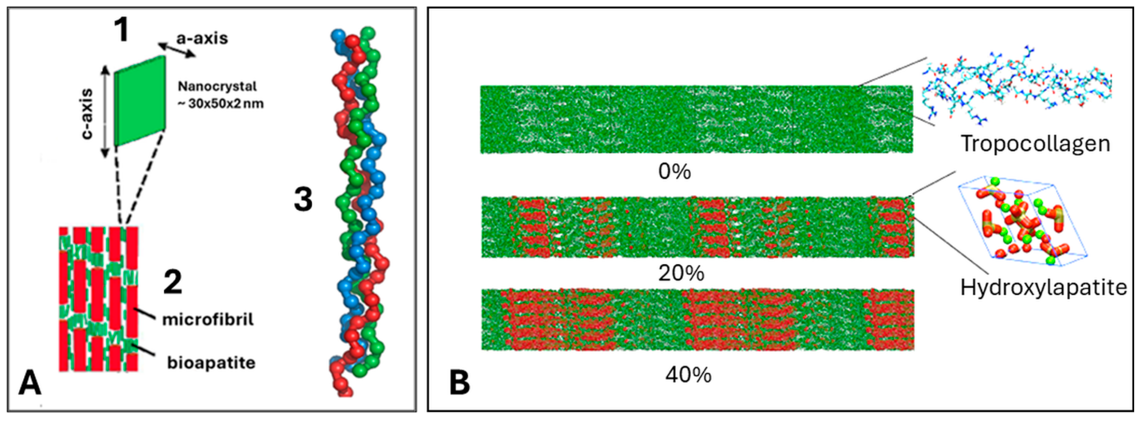
4. Hierarchical Structure of Bone

The realization that calcium orthophosphates are crucial constituents of bone matter has led eventually to their application in several medical disciplines. A major segment of the utilization of the calcium orthophosphate HAp is in the challenging fields of bone reconstruction, bone scaffolds, coatings for hip, knee, and dental implants, and vertebrae replacement [27].
Bone is a biological composite structure that during its growth is composed initially of soft, unmineralized tissue (osteoid) with embedded osteoblasts and osteocytes. These living cells secrete collagen I as well as non-collagenous bone matrix proteins, forming a complex network that will eventually be mineralized, whereby hydroxylapatite platelets crystallize in an oriented fashion in the gaps provided by the tropocollagen fibrils (Figure 3A).
Hence, bone can be regarded as a biocomposite consisting of Ca-deficient defect biological HAp nanocrystals of about 30 × 50 × 2 nm3 size, orientationally intergrown with triple helical strands of matrix proteins such as collagen I (ossein). Consequently, a spatially hierarchical organization exists that forms the basic structural units of bone [28,29]. Figure 3A shows schematically the hierarchical architecture of bone microfibrils [30]. Figure 3B shows a molecular mechanics model of the oriented intergrowth of hydroxylapatite nanocrystals with tropocollagen fibrils at different degrees of mineralization (0 to 40%) [31].
Figure 3. (A) Hierarchical nano-architecture of cortical bone, showing an individual crystalline platelet of HAp (1), an array of five collagen microfibrils with oriented intergrown HAp nanocrystals, which constitutes the smallest unit of the bone microstructure (2), and a triple helical strand of tropocollagen consisting of three polypeptide α-chains (3). Image modified after Ref. [30]. © Permission granted under Creative Commons Attribution 4.0 International License. (B) Collagen microfibril model with different degrees of mineralization. The HAp crystals are arranged such that their c-axes align with the fibril axis [31]. © Permission granted under Creative Commons Attribution-NC ShareAlike 3.0 International License.
Coatings 14 00787 g003

5. Osseoconductive Hydroxylapatite Coatings

Given the important role that HAp coatings applied to the surface of an endoprosthetic implant play, it is not surprising that synthetic HAp, with its pronounced biocompatibility, was first suggested as a useful material to be incorporated in the human body [32] 50 years ago. Soon after, HAp was deposited as a bioactive, i.e., osseoconductive coating on dental implants, followed by coating the metallic parts of hip implants [33].

5.1. Osseoconduction, Osseoinduction, and Osseointegration

Osseoconduction refers to the ability of a biocompatible material including hydroxylapatite to assist the development and growth of osteoblasts, blood capillaries, and perivascular tissue into the gap between the existing cortical bone bed and the implant that was created during the operation [27]. The process results in a bony surface with various channels, pores, and a matrix that provides a scaffold for the newly formed bone matter.
The term osseoinduction refers to the recruitment of immature cells and their stimulation to develop into preosteoblasts [34]. HAp-based bioactive implant coatings assist normal cell differentiation in surrounding tissues by creating a fertile environment for enhanced cell adhesion. Cytoskeletal microfilaments such as actin, myosin, actinin, and tropomyosin control cell shape and migration. They are coupled through specialized cell membrane proteins (integrins) to extracellular adhesion molecules (fibronectin, laminin, vitronectin, thrombospondin). An interfacial layer of HAp will adsorb these integrins in a favorable conformation and promote the formation of focal adhesion centers. Particular growth factors (cytokines) may also be recruited and adsorbed at specific HAp surface sites, further promoting osseoinduction. Cytokines include transforming growth factor-β, insulin-like growth factor-1, tumor necrosis factor-α, and recombinant human bone morphogenetic proteins (rhBMPs). They stimulate osseogenesis by supporting the transformation of undifferentiated mesenchymal precursor cells to osteoprogenitor cells preceding endochondral ossification.
Finally, osseointegration describes the process by which interfacial bone is formed between an implant and living bone as a defense reaction akin to FBR. Osseointegration is the requirement for the desired long-term stability of an endoprosthesis. The process is characterized by the firm anchoring of a surgical implant by the growth of bone around it without fibrous tissue formation at the interface [34]. When an implant is integrated into the cortical bone bed, no progressive relative movement occurs between the implant and the bone with which it is in direct contact.

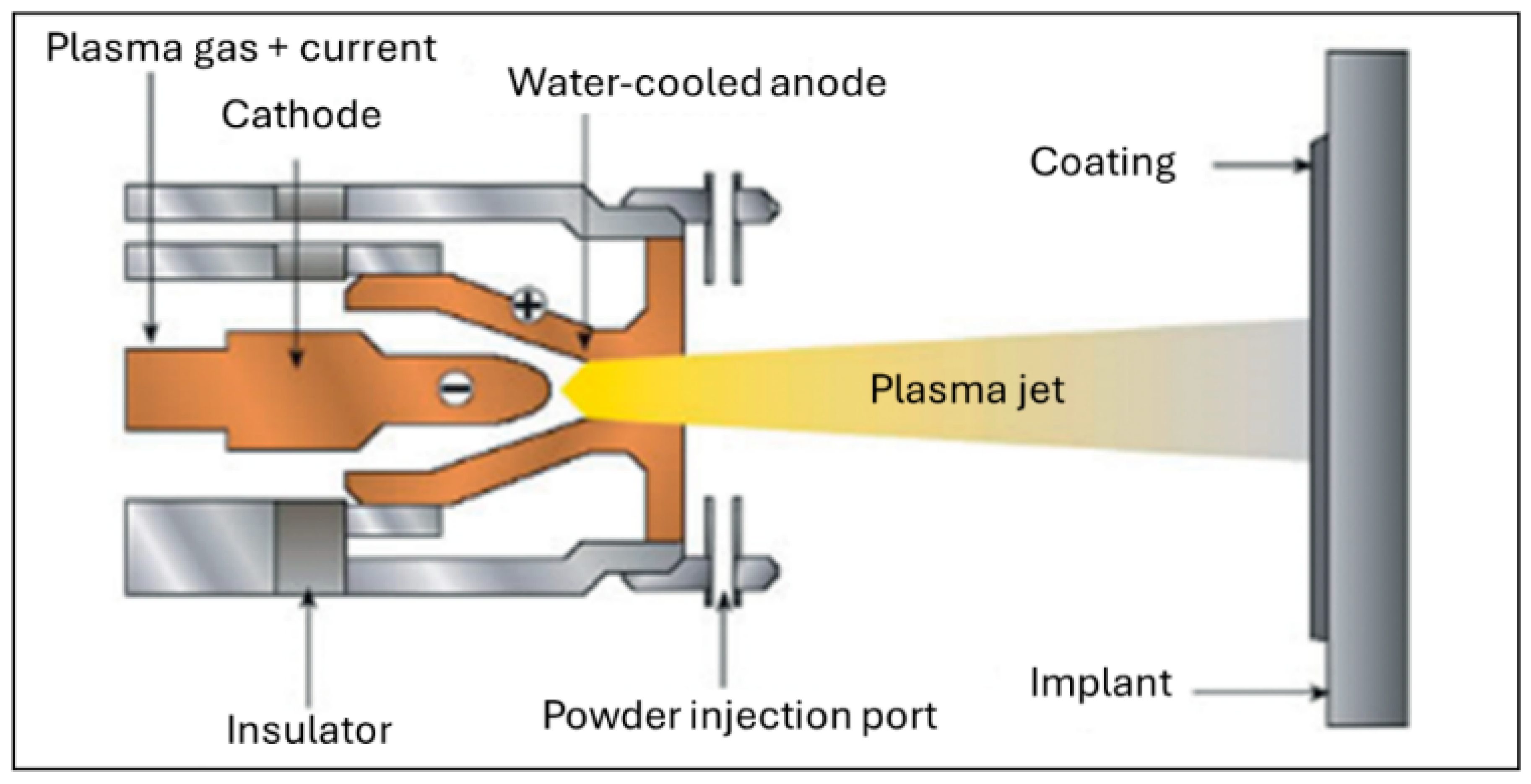
5.2. Deposition Techniques

A plethora of techniques are available and used to apply HAp coatings. These can be divided into non-thermal and thermal methods. Non-thermal methods carried out at or near ambient temperature include biomimetic deposition, electrochemical (ECD) and electrophoretic deposition (EPD), sol-gel deposition by dip and spin coating, hydrothermal deposition, and radiofrequency magnetron sputtering (r.f.MS). Thermal methods include atmospheric (air) plasma spraying (APS), micro plasma spraying (MPS), low-energy plasma spraying (LEPS), low pressure (vacuum) plasma spraying (LPPS/VPS), suspension plasma spraying (SPS), solution precursor plasma spraying (SPPS), plasma electrolytic oxidation (PEO), pulsed laser deposition (PLD), and other less frequently utilized techniques such as cold gas dynamic spraying (CGDS), flame spraying (FS), high velocity suspension flame spraying (HVSFS), high velocity oxyfuel spraying (HVOF), and chemical vapor deposition (CVD) [8]. The properties and application of hydroxylapatite coatings deposited by suspension plasma spraying will be briefly discussed in Section 5.3.7.
The preferred deposition method of biomedical HAp was and still is atmospheric plasma spraying [27,35,36,37] (Figure 4). This technique offers a fast, well-controlled, and mature way to coat metal implant surfaces with a thin, continuous layer of HAp, even though thermal dehydroxylation and decomposition, line-of-sight limitations, and porosity, residual stresses, and cohesion and adhesion issues are affecting the process and thus require close control of the intrinsic plasma spraying parameters. A comparison of the properties of HAp coatings deposited by different thermal and non-thermal methods, as well as their benefits and limitations, can be obtained from the comprehensive monograph by Heimann and Lehmann [8].
Plasma spraying is a useful tool to coat the surface of any reasonably thermally stable metallic, ceramic, or even polymeric material with a thin layer of a second material possessing a well-defined congruent melting point. Since the hot molten droplets will be rapidly quenched when arriving at the relatively cool implant surface, they form easily soluble amorphous phases by a mechanism akin to Ostwald’s rule of steps. Accordingly, during spraying of HAp, ACP of variable composition forms as will be discussed below. Despite the apparent simplicity of the process, in practice several limitations exist; these limitations render many issues of adhesion, porosity, thickness, and thermal alteration of coatings highly challenging. In addition, the ubiquitous presence of residual stresses and line-of-sight restrictions require close attention.
The physics of plasma spraying involves the action of a plasma that is generated by ionization in an electric potential field of a suitable gas, preferentially argon or nitrogen. A plasma is considered the ‘fourth state of matter’ and is composed of positively charged ions, electrons, neutral gas atoms, and photons that make the plasma luminous. Charged ions and electrons moving within the plasma column generate a magnetic field B   that is perpendicular to the direction of the electric field with a current   j . The vector cross-product [ j × B ] constitutes the magnetohydrodynamic Lorentz force with a vector that is mutually perpendicular to the vectors j and B . As a result, an inward moving force that constricts the plasma column by the so-called magnetic pinch is generated. In addition, there exists a thermal pinch originating from the decreased conductivity of the plasma gas at the water-cooled wall of the anode (Figure 4). This effect results in an increase of the current density at the center of the plasma column. Consequently, the charged plasma concentrates at the central axis of the plasmatron, thereby further constricting the plasma column. This effects a drastic rise of the pressure in the plasma core, causing it to be blown out of the plasmatron as a plasma jet at a supersonic velocity [36,38].

5.3. Property Requirements and Performance Profile of Hydroxylapatite Coatings

HAp suffers dehydroxylation and subsequent decomposition in the plasma jet, which reaches temperatures up to 15,000 K and beyond. Partially dehydroxylated calcium orthophosphate phases such as OHAp and/or OAp are restored to fully stoichiometric HAp by contact with extracellular fluid (ECF) in vivo. Nevertheless, despite its apparent drawbacks, to this date atmospheric plasma spraying is the only biomedical coating deposition method certified and approved by the US Food and Drug Administration (FDA) [39] and many other national standardization authorities.
Figure 5A shows the typical surface of a plasma-sprayed HAp coating. One of the most crucial properties of HAp coatings is their biostability in vivo, which increases with increasing (i) phase purity, (ii) crystallinity, (iii) coatings density, and (iv) coating thickness. As discussed below, requirements (i) and (ii) are poorly met by plasma spray technology owing to the incongruent melting behavior of HAp, and requirement (iii) must be relaxed to guarantee appropriate biological performance because a certain degree of porosity must be obtained for optimum cell ingrowth. Finally, requirement (iv) calls for a coating thickness of at least 50 µm. Although thicker coatings are more stable against in vivo resorption, they bear the risk of cracking, spalling, and delamination owing to increased residual coating stresses (Figure 5B; see also Section 5.3.8).
Coating integrity, cohesive and adhesion strengths, and surface roughness can be estimated by checking the flow characteristics of the molten particles using a simple empirical ‘wipe’ test. A flat surface is quickly brought into the way of a molten particle trajectory with the intention to capture only a few particles that after solidification can be investigated with light optical or electron microscopy. Figure 6 shows typical examples of HAp particle splats deposited under low pressure conditions [36]. The plasma enthalpy increases from Figure 6A–D. Figure 6A shows that the enthalpy supplied to the particle is insufficient to achieve melting. Figure 6B shows a splat pattern of a particle the outer rim of which has been melted, but its core has remained highly viscous, as revealed by its porous sponge-like appearance. Finally, Figure 6C shows a well-molten splat with only a few micropores, whereas Figure 6D depicts an ‘exploded’ splat typical of a severely overheated particle. By comparing Figure 6A,D, this technique reveals how sensitive the parameter selection is: varying the stand-off distance, i.e., the distance between the plasmatron exit nozzle and the target surface by only a few millimeters changes the flow characteristics dramatically.

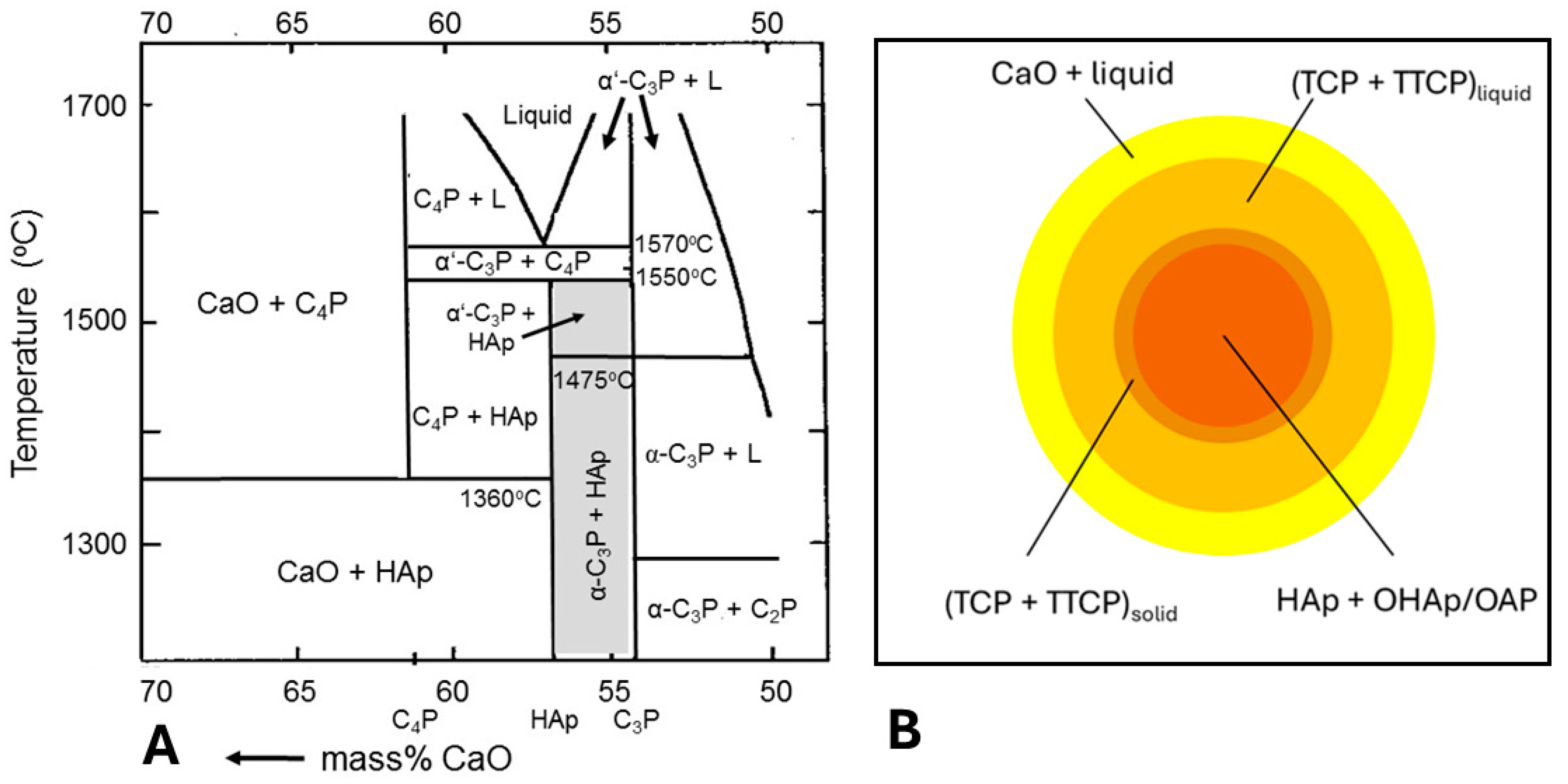
5.3.1. Incongruent Melting and Thermal Decomposition of HAp: Phase Composition

The temperature of the plasma jet of commercial APS equipment exceeds 15,000 K [36]. This extremely high temperature causes severe structural changes of HAp, even though the residence time of the powder particles in the plasma jet is very short, in the range of hundreds of microseconds to a few milliseconds. Since HAp melts incongruently at 1570 °C (Figure 7A), it decomposes to tricalcium orthophosphate (α’-TCP, Ca3(PO4)2), tetracalcium orthophosphate (TTCP, Ca4O(PO4)2) and finally CaO during the four consecutive steps indicated in Table 1.
Based on this decomposition sequence, a simple shell model of the inflight evolution of calcium phosphate phases was adopted by Graßmann and Heimann [41] and Dyshlovenko et al. [42] (Figure 7B). Owing to the low thermal conductivity of HAp of ~1 W/mK, the inner core of a particle is still below the incongruent melting point and only dehydroxylation steps 1 and 2 come to bear, resulting in OHAp and OAp, short-range ordered (SRO) structures with lattice vacancies □. In contrast, the outer shells consist of a mixture of liquid TCP + TTCP (step 3) and liquid + solid CaO (step 4). According to Dyshlovenko et al. [42], there may exist a thin shell of solid TCP + TTCP. On impact with the cool surface of an implant to be coated, the outer liquid parts of the incoming particle splash across the surface and solidify preferentially as ACP.
Figure 7. (A) Partial quasi-ternary CaO-P2O5-(H2O) phase diagram at a water partial pressure of 65.5 kPa (after Riboud [43]). The area of interest is shaded, showing the transformation of α-C3P to α’-C3P above 1475 °C and the incongruent melting of HAp and decomposition beyond 1570 °C to form C3P (α’-TCP) and C4P (TTCP). © With permission of Wiley-VCH. (B) Model of the phase composition of a spherical HAp particle thermally decomposing during flight in the high temperature plasma jet at a low water partial pressure of 1.3 kPa [41,42].
Coatings 14 00787 g007

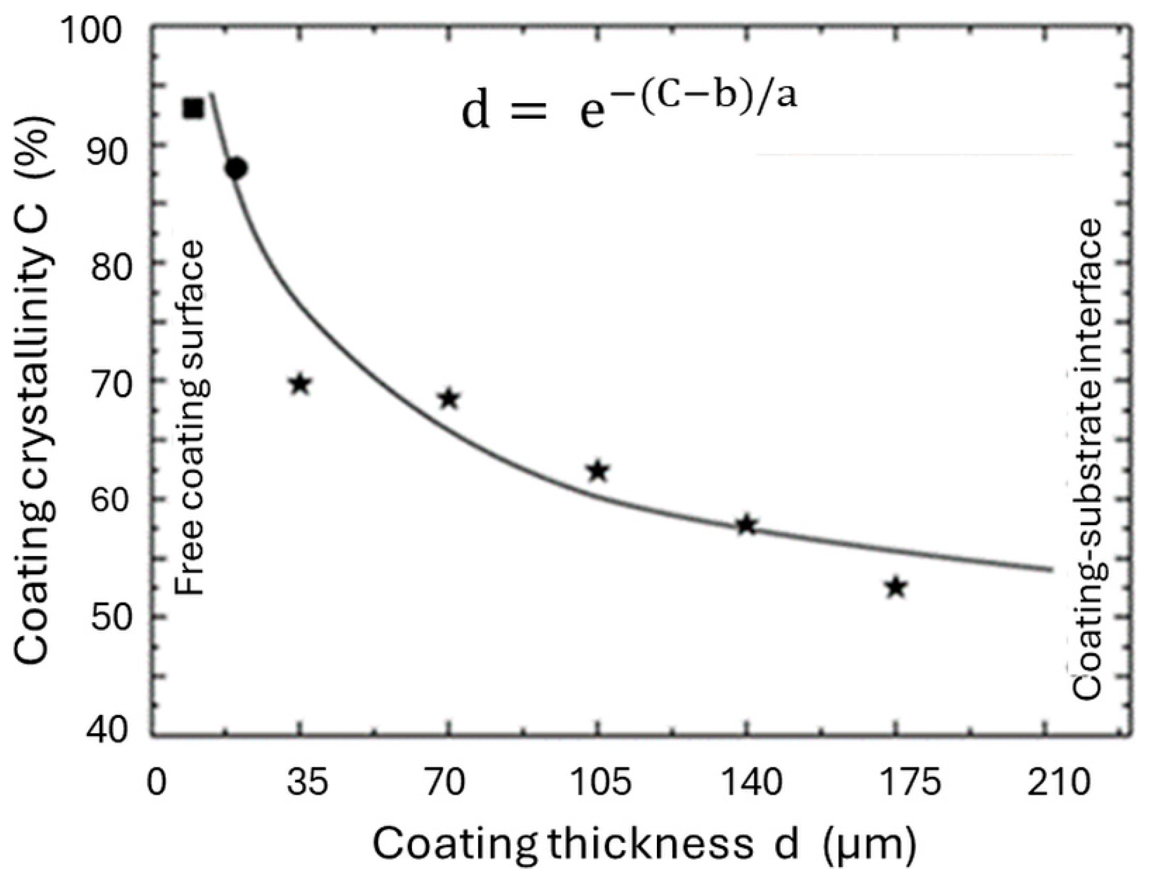
5.3.2. Degree of Crystallinity

As far as coating crystallinity is concerned, there are several aspects to consider. Fully crystalline and well-ordered HAp exhibits low solubility that does not lend itself easily to osseoconductivity as it causes the coating to behave largely like a bioinert material. Hence, fully crystalline, stoichiometric HAp inhibits cell proliferation as evidenced by decreased alkaline phosphatase (ALP) activity [44]. The enzyme ALP is highly expressed in the cells of mineralized tissue and plays a critical function in the formation of hard tissue. Also, reduced osteocalcin secretion has been observed in the presence of fully crystallized and well-ordered HAp [45]. Osteocalcin has routinely been used as a serum marker of osteoblastic bone formation and is believed to act in the bone matrix to regulate mineralization.
Synchrotron radiation X-ray diffraction of coating cross-sections reveals that the crystallinity of the coating decreases exponentially with depth, from about 93% at the surface to about 50% at the substrate-coating interface (Figure 8). In parallel, the amount of more or less pristine HAp decreases linearly from some 80 mass% (the remaining phases were 15 mass% TTCP, 4 mass% ß-TCP, and 1.5 mass% CaO) at the free, i.e., outermost coating surface to less than 15 mass% immediately at the metal interface [46]. Additional studies of the depth-resolved cross-sectional phase composition of plasma-sprayed HAp support this finding [47].
The amorphous calcium phosphate (ACP) (Figure 9A,B) that accumulates at the immediate interface of coating and substrate as the first product of solidification during plasma spraying provides a low-energy path of coating delamination [48] as it dissolves preferentially during in vivo exposure to extracellular fluid (ECF). A certain degree of resorbability/solubility is required to obtain a sufficiently high concentration of Ca2+ and PO43− ions conducive to precipitating secondary HAp micro- to nanocrystals for sustained biomineralization and thus, osseointegration. Consequently, careful engineering of the plasma spray parameters is mandatory. To control coating crystallinity, the application of a thin bond coat separating the metallic substrate and the HAp coating has been suggested [49]. The advantages of titania, zirconia or zirconium titanate bond coats include [50]:
  • Increase of adhesion to both metal and HAp. For example, a titania bond coat is thought to act as an extension of the native oxide layer on metallic titanium that may interact with HAp to form a thin reaction layer of perovskitic calcium titanate.
  • Reduction of the thermal decomposition of HAp by inhibiting the heat flow using a thin titania bond coat film with low thermal conductivity (~1 W/mK) as opposed to a Ti6Al4V substrate (~7 W/mK).
  • Reduction of the formation of amorphous phase that forms by a quenching contact immediately at the metal interface. An increase in crystallinity is caused by the thermal barrier function of a bond coat that prolongs solidification time and thus allows the ACP to nucleate apatite and crystallize. Experimental NMR results [50] show that as-sprayed coatings without a bond coat contain only 46 mass% well-ordered HAp at the free coating surface as contrasted with 62 mass% in coatings with a titania bond coat. During incubation for 12 weeks in r-SBF [51], these values increase by dissolving TCP, TTCP, CaO, and ACP phases to 74 mass% and 92 mass%, respectively.
  • Reduction of residual coating stresses by reducing the gradient of the coefficient of thermal expansion between the metal substrate and the ceramic overlayer.
Figure 9A shows a STEM image of a cross-section of a plasma-sprayed titanium dioxide bond coat that separates the titanium alloy from the ACP layer. As ascertained by Figure 9B, the bond coat was found to consist of the metastable orthorhombic brookite polymorph of titania with low surface energy instead of the expected thermodynamically stable rutile or Magnéli-type phases TinO2n−1. It was likely formed as the result of quenching by a mechanism governed by Oswald’s rule of steps. The columnar brookite crystals interdigitate with both the ACP and the Ti6Al4V substrate and thus may provide some resistance against the shearing forces expected in vivo.

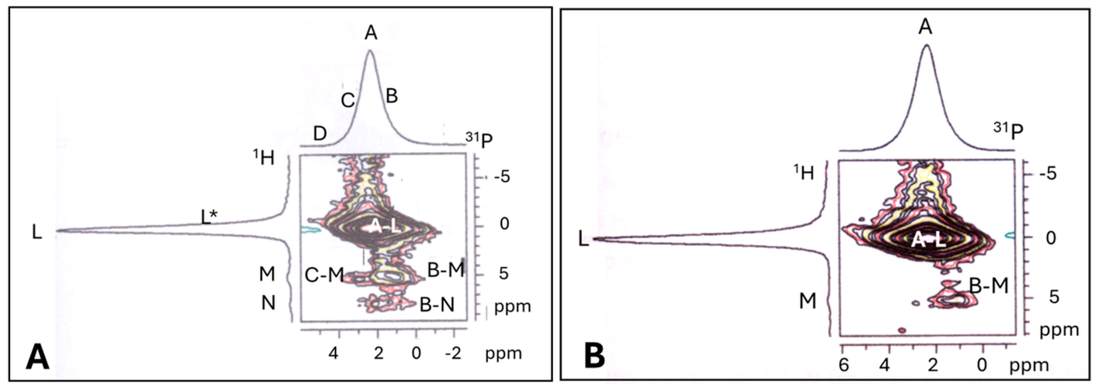
5.3.3. Assessment of Structural Order in Hydroxylapatite Coatings: Raman and NMR Studies

Application of a high temperature introduces severe structural disorder in as-received crystalline HAp. This has noticeable repercussions on its mechanical, chemical, and biological behavior. Detailed information on the structural order of calcium phosphate phases can be obtained by Raman and NMR spectroscopies [50,52,53,54]. Figure 10A shows the full range of the laser-Raman spectrum of an atmospheric plasma-sprayed HAp coating with the four principal vibration modes of the PO43− tetrahedron indicated. Figure 10B shows the Gaussian–Lorentzian deconvolved principal Raman mode ν1. The weak shoulders at 949 cm−1 and 971 cm−1 may be assigned to ACP and ß-TCP, respectively [55]. The splitting of the triply degenerate ν3 and ν4 modes shown in Figure 10A is presumably caused by an increasingly perturbed PO43− environment owing to increasing dehydroxylation and to plasma spray-induced disorder of the hydroxyl ions located in the [00.1] lattice direction of HAp, respectively [52].
Figure 10C reveals that during low-energy plasma spraying (LEPS), distinct high intensity bands of OAp are still present [53], in contrast to high-energy plasma spraying, during which OAp decomposes to form ß-TCP and TTCP, consistent with step 3 of the decomposition sequence (Table 1). Consequently, when it is desired to maintain oxyapatite in the coating, the electrical energy input into the plasma spray process and the attendant attainment of high temperatures must be drastically reduced.
More detailed data on the type and degree of structural disorder that HAp suffers during plasma spraying has been obtained by high resolution X-ray diffraction [57] and solid-state nuclear magnetic resonance (NMR) spectroscopy [49,50,58,59]. Determining the position as well as the shift of 1H-magic angle spinning (MAS) and 31P-MAS NMR bands provide important clues to determine the environment of PO43− tetrahedra and thus, allows identifying dehydroxylation phases such as OHAp and OAp as well as decomposition phases such as TCP, TTCP, and CaO as well as ACP.
Figure 11 shows the 1H-MAS (A) and the 31P-MAS (B) NMR spectra of a plasma-sprayed HAp coating [50,58,60]. The insets refer to completely ordered, stoichiometric, and highly crystalline HAp. In Figure 11A, the high intensity band L at −0.1 ± 0.1 ppm can be assigned to the proton band position of well-ordered crystalline and stoichiometric HAp, and the isotropically shifted weak band L* at −1.3 ± 0.3 ppm may be assigned to protons present in OHAp. The broad M band at 5.2 ± 0.2 ppm indicates isolated pairs of strongly coupled protons in the channels parallel to the c-axis in HAp [58]. Band G at ~1.3 ppm may belong to free water molecules attached to the surface of HAp particles [59]. The 31P-MAS NMR spectrum shown in Figure 11B is more complex. The principal band A at 2.3 ± 0.1 ppm is associated with highly crystalline hydroxylapatite (see inset) whereas the other bands of the Gaussian–Lorentzian deconvolved NMR spectrum represent dehydroxylation (B,C) and decomposition (D) phases. Band B at 1.5 ± 0.2 ppm signals a strongly distorted PO43− environment without OH neighbors as suggested for OAp, and band C at 3.0 ± 0.2 ppm has been assigned to distorted PO43− tetrahedra associated with single or paired OH ions as in OHAp [58]. Finally, band D at 5.0 ± 0.2 ppm may represent very strongly distorted PO43− tetrahedra lacking OH ions as present in TCP, TTCP, and OAp.
Supporting 2D-double quantum 1H/31P cross-polarization (CP) heteronuclear correlation (HETCOR) NMR spectroscopy (Figure 12) further suggests that the D-band may indeed represent OAp, the chemical shift of which is identical to that of TCP and TTCP, thus confirming the thermal decomposition sequence HAp → OHAp → OAp → TTCP/TCP shown in Table 1.
Figure 12A shows the main A-L correlation band of crystalline, stoichiometric HAp together with the weak satellite correlation bands C-M and B-M that can be associated with a partially dehydroxylated apatite structure, i.e., OHAp sensu lato and Ca-deficient ACP, respectively [49]. The correlation bands B-L and C-L are swamped by the intense A-L band but can be visualized by Gaussian–Lorentzian deconvolution of the A-L band (not shown here but contained in Ref. [60]). The weak and broad band N in the individual proton spectrum at ~7.5 ppm was assigned to isolated OH-groups in the c-channel of HAp [61]. Figure 12B shows the same coating incubated in r-SBF [51] for 8 weeks at 37 ± 0.5 °C. The satellite correlation bands C-M and B-N have disappeared and B-M has weakened, indicating that the SRO phases were dissolved. In parallel, the intensity of the A-L band of more or less pure, stoichiometric hydroxylapatite has increased, reflecting its relative increase from about 67 mass% in the as-sprayed coating to 85 mass% after 8 weeks of incubation. In parallel, the amount of TTCP decreased from about 26 mass% to 10 mass%, whereas that of ß-TCR remained nearly constant at 5 mass%. Minor amounts of CaO (around 1.5 mass%) have disappeared completely after a few days of incubation [60].
In addition, quantitative 31P magic angle spinning (MAS) solid-state NMR allows distinguishing between PO43− groups of apatitic calcium phosphates and HPO42− groups of non-apatitic calcium phosphates (Figure 13). Non-apatitic calcium phosphate is thought to be a measure of the maturity of bone; with time, the non-apatitic precursor transforms to true apatite [62].
For a long time, biological apatite has been described as Ca- and OH-deficient carbonated hydroxyapatite (CHA) in which a fraction of the PO43− lattice sites is occupied by HPO42− ions, resulting in the tentative formula Ca10−x(HPO4)x(PO4)6−x (OH, O, Cl, F, CO3, □)2−x ∙ nH2O; 0 < x < 1; n = 0–2.5 (see above). However, more recent solid-state NMR studies have revealed that the surface of mature bone mineral particles does not consist of well-ordered HAp at all but of hydrated ACP [63], a contention that mirrors an earlier suggestion by Jäger et al. [59]. They proposed that HAp nanoparticles comprise a stoichiometric and highly crystalline core that is covered by an extremely thin (~1 nm) layer of a disordered calcium phosphate phase having a Ca/P-ratio of ~1.5.

5.3.4. Crystallographic Structure of Hydroxylapatite

Figure 14A shows a ball-and-spoke model of the crystallographic structure of HAp. Hydroxylapatite Ca10(PO4)6(OH)2 is a member of a large group of chemically different but structurally identical compounds with space group P63/m (176), and with the general formula M10(ZO4)6X2 (M = Ca, Pb, Cd, Zn, Sr, La, Ce, K, Na; Z = P, V, As, Cr, Si, C, Al, S; X = OH, Cl, F, CO3, H2O, □). The crystallographic structure of HAp comprises Ca [9] polyhedra sharing faces and thus forming chains running parallel to the crystallographic c-axis [00.1], that is, a 63 screw axis. These chains form a hexagonal net and share edges and corners with PO4 tetrahedra. OH ions are situated in wide hexagonal channels parallel to the crystallographic c-axis [00.1].
Caused by the presence of open channels, HAp is able to incorporate many other large ions that fill either cationic Ca2+ positions or anionic OH and PO43− positions. This happens without large distortions of the crystal lattice, thus maintaining the P63/m space group symmetry of pure stoichiometric HAp. In biological apatite, Ca2+ is partially replaced by metabolically important cations such as Na+, Mg2+, Sr2+, K+ and some trace elements such as Pb2+, Ba2+, Zn2+, and Fe2+. Substitution of PO43− anions with CO32−, SiO44−, and SO42− and OH with Cl, F, and CO32− enables several biochemical pathways leading to the formation and transformation of bony matter [27,66,67]. This compositional variability of biological apatite is the root cause of its high biocompatibility and osseoconductivity. In particular, the OH positions can be occupied by mobile O2− ions and lattice vacancies and thus assist in the kinetics of the dehydroxylation of HAp during plasma spraying and biomineralization in vivo.

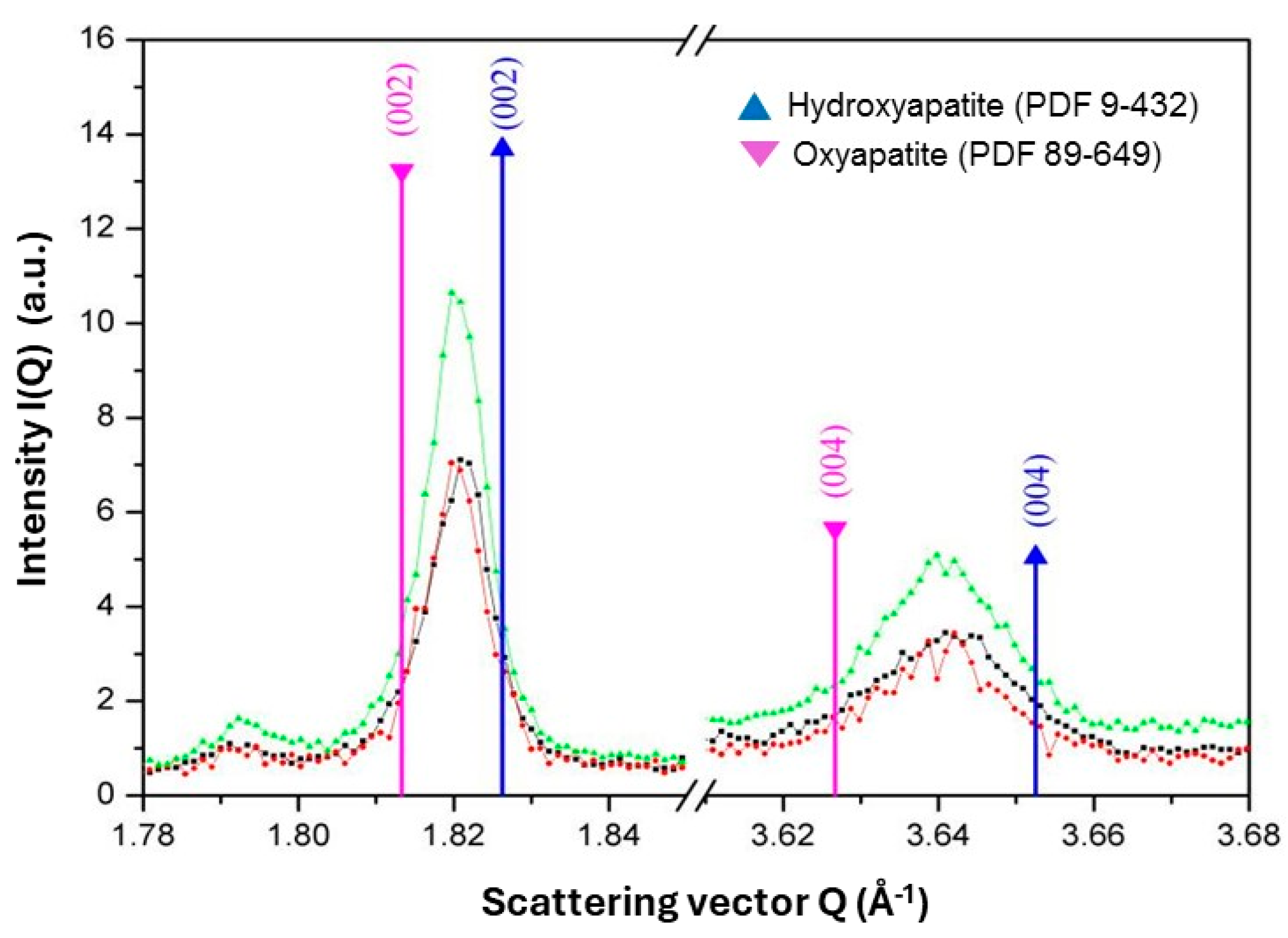
5.3.5. Oxyapatite: Fact or Fiction?

Oxyapatite (OAp), Ca10O(PO4)6 is considered the product of the complete dehydroxylation of HAp [12], but it converts back to stoichiometric HAp in the presence of water either during cooling of the as-sprayed coating in moist air or by an in vivo reaction with extracellular fluid (ECF). As discussed in Section 3 above, there is evidence against the existence of OAp as a thermodynamically stable phase.
Investigation into the structure of OAp has suggested that a linear chain of O2− ions and associated vacancies parallel to the c0-axis may exist [19], as shown in Figure 14B. More recent calculations involving a density-functional theory supported by a local-density approximation (DFT-LDA) and first-principles pseudo-potentials [20] hinted at a hexagonal ‘c-empty’ structure Ca10(PO4)62 having a stable total-energy minimum. During thermal dehydroxylation, the mirror planes m (Figure 14A) of the parent HAp are lost, thereby transforming the symmetry of the screw axis 63 to that of the polar axis 6 ¯ .
Confirming the existence of OAp by classic X-ray powder diffraction is challenging or even impossible because the length of the c0-axis of OAp is only slightly larger than that of HAp [68]. This accounts for only a small shift of the (00.2) interplanar spacing in the direction of lower diffraction angles. This means that very accurate measurements are called for when using X-ray diffraction using synchrotron radiation. Indeed, high resolution synchrotron X-ray diffraction (Figure 15) reveals that the average c0 distance of OAp is (at 0.6900 nm) about 0.3% longer than the c0 lattice distance of stoichiometric HAp (0.6880 nm), confirming the postulated expansion of the unit cell (Figure 14B) that is arguably related to the larger Shannon radius of the O2− ion of 135 pm, in contrast to that of the OH ion (118 pm) [65].

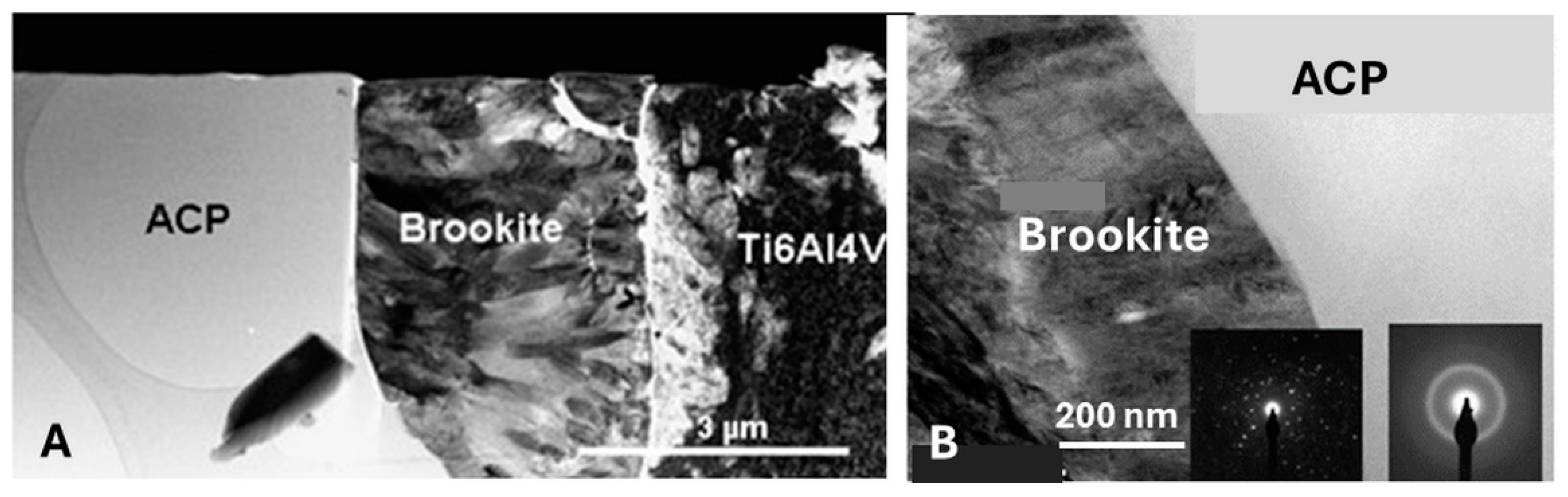
5.3.6. Transformation of Amorphous Calcium Phosphate (ACP)

Of the sixteen available positions for OH ions in the unit cell of HAp, only 50% are statistically occupied, leaving 8 vacancies along [00.1]. This leads to direction-dependent differences in the mobility of OH ions as well as the associated Ca2+ ions, relevant for the transformation of ACP to crystalline HAp, either in vitro in contact with simulated body fluid (SBF) (Figure 16) or in vivo by extracellular fluid (ECF) contact. The extent of electrical conductivity [69] as well the kinetics of the stepwise dehydroxylation forming OAp [22] is also dependent on the mobility of OH ions.
Figure 16A shows the formation of porous crystalline HAp from ACP during in vitro contact with r-SBF [70]. Crystallization likely occurs by a fluid flow of SBF along cracks and fissures within the coating to form porous HAp with Ca/P = 1.65 as well as dense, needle-like crystalline Ca-depleted calcium orthophosphate CaP with Ca/P~1.36. Such needles with a comparable composition thought to be akin to bone-like apatite can nucleate from ACP and are implicated in mediating osseointegration [71].
The STEM image of Figure 16B demonstrates how during incubation of the coating in r-SBF the transformation front sweeping across the coating layer changes ACP to crystalline phases. Porous but well-crystallized HAp has been formed at the trailing edge of the transformation front (upper right corner), whereas nanocrystalline HAp appears at the leading edge. In addition, within the transformed section of ACP, ß-TCP and TTCP crystallites were detected as decomposition phases of the original HAp [49].

5.3.7. Coating Porosity, Surface Roughness, and Surface Nanotopography

Close control of the coating’s porosity and surface roughness are required when attempting to enhance the mechanical and biomedical performance of medical implants. Optimum coating porosity, pore size distribution, and fractal surface roughness are vital preconditions for the uninhibited ingrowth of bone cells [72]. However, the risk of bonding degradation involving mechanisms such as cracking, spalling, delamination, or dissolution during in vivo contact with aggressive ECF decreases with increasing coating density [73]. These two antagonistic requirements have to be carefully assessed, balanced, and controlled [41]. This is particularly important when considering the risk of a release of coating particles into the body environment. HAp particles are known to be distributed by the lymphatic system throughout the body, leading to inflammatory FBR events characterized by the formation of giant cells and phagocytes as described above in Section 2 [74]. Thus, balancing the two antagonistic porosity requirements is challenging and needs target-oriented design and control of the appropriate intrinsic plasma spray parameters by statistical design of experiments (SDE) and statistical process control (SPC) methodology. Parameters influencing the coating porosity include powder particle size and the degree of particle melting. Particle melting degree and kinetics have been found to be complex functions of plasma gas composition, plasma enthalpy, powder injection geometry and position, and spray distance [37]. This type of porosity control is difficult because atmospheric plasma spraying frequently yields dense coatings that cannot satisfy the biomedical requirements that stipulate pore sizes of at least 75 µm [75]. Figure 17 shows the effect of the degree of particle melting, expressed as the fraction of molten particles formed, on crystallinity, porosity, and adhesive bond strength of plasma-sprayed HAp [76]. As evident, an increasing fraction of molten HAp particles causes the porosity and the degree of crystallinity of the coating to decrease, but the adhesive bond strength to increase. Hence, careful adjustment of the critical intrinsic plasma spray parameters is required to guarantee optimum coating performance.
Dense, i.e., pore-free hydroxylapatite coatings deposited by APS inhibit the attachment, migration, spreading, and proliferation of bone cells. Hence, research is underway to increase the coating porosity to conform to biomedical requirements. Suspension plasma spraying (SPS) provides coatings with drastically enhanced porosity [27,77] that allows the uninhibited ingrowth of osteoblasts. Consequently, HAp coatings deposited by SPS may impart improved biocompatibility, provided sufficient adhesion can be engineered. One way to increase porosity consists of adding pore-forming agents such as ammonium carbonate to the suspension [78].
An important prerequisite for optimum cell adhesion and proliferation is an appropriate surface nanotopography. Assessing the nature of micro- and nano-roughened plasma-sprayed surfaces may be done by involving fractality theory [79,80]. Fractality considerations were used by Gentile et al. [81] in experiments studying cell proliferation on silicon proxy surfaces that were electrochemically etched to obtain varying degrees of roughness while maintaining comparable surface energies. The surface profiles were found to be self-affine fractals. Their average roughness Ra increased with increasing etching time from ~2 nm to 100 nm, showing fractal dimensions ranging from D = 2 indicating a nominal flat surface, to D = 2.6. Etched silicon surfaces with Ra between 10 and 45 nm revealed a near Brownian surface topography with D~2.5. Such moderately rough surfaces with large fractal dimensions were found to support efficient cell proliferation. Gittens et al. [82] investigated the influence of surface topography on the osseointegration of spinal implants and concluded that apart from the implant design, the experience of the physician, and the age and bone status of the patients, the final success of a spinal implant’s integration is to a high degree dependent on the surface characteristics of the implant, i.e., surface roughness, surface chemistry, and surface energy. This has been echoed by a recent review of the role of implant surface modification in osseointegration [83]. The nanotextured architecture of implant surfaces with asperities < 100 nm affects surface roughness, surface area, and surface energy. Nanotextured implant surfaces promote osteoblast contact signaling, adhesion, and proliferation and have shown enhanced cell spreading and filipodia extension [84]. Means to engineer implant surfaces toward suitable nanotopography include mechanical roughening by grit blasting, electron beam lithography, nanoimprinting, chemical etching, reactive ion etching, laser scribing, selective laser sintering, and electrospinning [85].

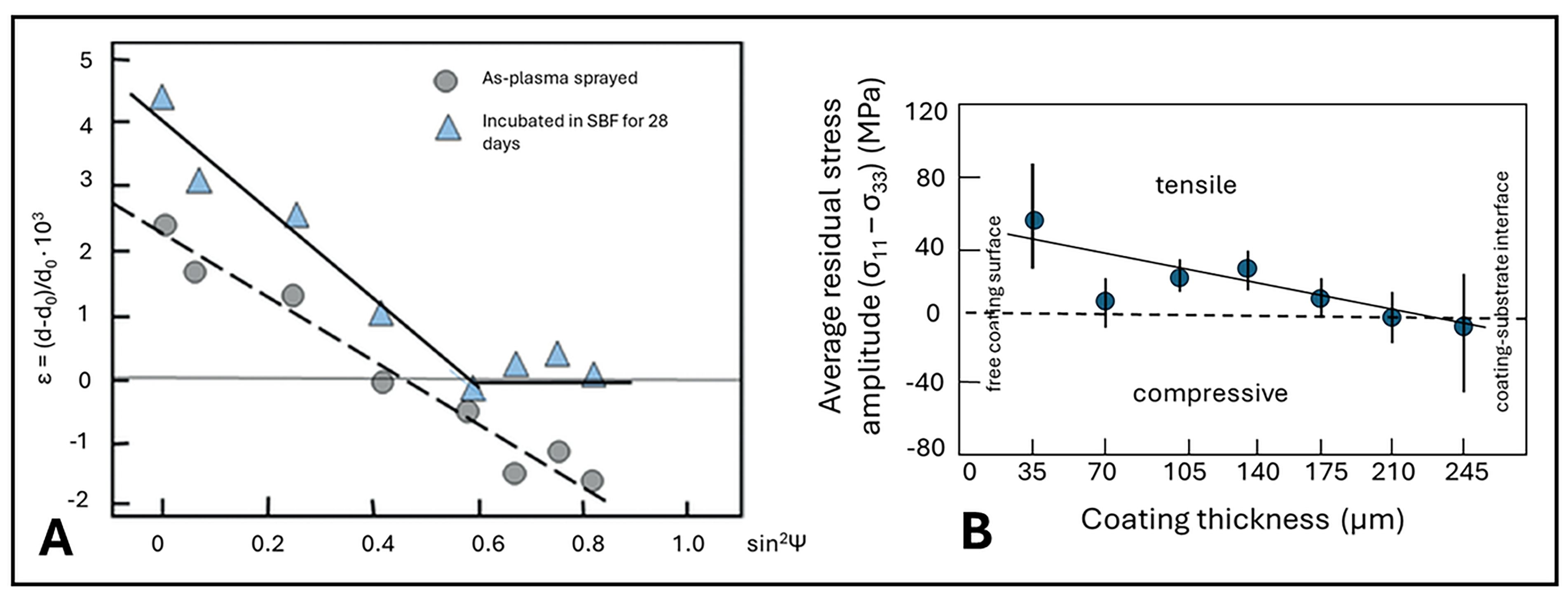
5.3.8. Residual Coating Stresses

Plasma spraying is a rapid solidification process during which the molten or semimolten particles strike the substrate surface with supersonic velocity, which may lead to reverberating shock waves that provide additional heat to the deposit and slow down its solidification by adding a thermal pressure component [36,86]. Determination of the direction and the extent of residual coating stresses can be experimentally assessed by X-ray diffraction (sin2Ψ-technique), Almen-type curvature measurements, the hole-drilling strain gauge method, or photoluminescence and Raman piezospectroscopies [8].
Control of residual coating stresses is mandatory to obtain HAp deposits that adhere well to the implant substrate and thus guarantee reasonable resistance to chipping, spalling, and complete delamination. The large temperature gradient experienced during the plasma spray process generates residual stresses in the deposited coating [36]. There are two main types of stress, thermal and quenching stress. Combined with the complicated solidification process within the coating, these stresses are the two main contributors to the overall residual stress [27].
Thermal stress, σc can be expressed by the Dietzel equation
σ c = { E c ( α c α s ) T 1 v c + [ 1 v s E s ] ( d c d s ) } ,
where E is Young’s modulus of elasticity, α is the thermal expansion coefficient, ΔT is the temperature difference between coating and substrate, ν is the Poisson’s number, and d is the thickness. The subscripts c and s refer to the coating and the substrate, respectively. At given values of E and ν, σc increases with increasing coating thickness dc. Hence, the risk of deleterious coating destruction is higher in thick coatings compared to thin ones. Depending on the sign of (αc − αs), thermal stresses can be tensile or compressive.
The origin of quenching stress lies in the effect of molten particles impacting the cool substrate, whereby their contraction during solidification is restricted by clamping adherence to the roughened substrate surface. This leads to tensile stress in the coating [87,88,89,90,91], frequently resulting in cracking when the cohesive coating strength can be overcome (Figure 5B). The first coating layer adjacent to the interface, consisting of ACP [70], will critically control both the magnitude and the sign of the residual stress. In addition, the ACP layer is known to provide a low-energy fracture path and may eventually cause coating delamination when tensile or shear stresses occur during movement in the post-operative phase. The transformation of ACP (Figure 16) to crystalline calcium phosphate phases during incubation in SBF [70,92] and presumably during in vivo contact with ECF will result in stress relaxation [93]. This reduces the risk of coating failure by delamination as shown in Figure 18A. The figure shows the interfacial coating strain ε = (d − d0)/d0·10−3 of as-sprayed (dots) and incubated (triangles) HAp coatings deposited by APS on Ti6Al4V substrates as a function of sin2ψ, where ψ is the tilt angle toward the X-ray beam [94,95].
When the coating is in tension, ε ∞ d − d0 increases. When in compression it decreases. As shown in Figure 18A, the plasma-sprayed HAp coatings measured by the sin2Ψ method is at a rather strong tensile stress created by the thermal mismatch during the cooling of the deposited layer to room temperature. This tensile stress will relax during incubation in SBF, when the high levels of ACP thought to be a main contributor to the residual stress transform to different calcium phosphate phases (see Figure 16B), most notably Ca-depleted defect HAp. Hence, the layer of bone-like secondary apatite deposited at the outermost rim of the samples will be decoupled from the declining stress field, and thus reveal close to zero stress (triangles in Figure 18A). At the free coating surface, the tilt angle Ψ is 0° (sin2Ψ = 0), i.e., the X-ray beam is tangential to the surface in grazing incidence. With increasing tilt angle Ψ, deeper areas of the coating are being probed, until at 90° (sin2Ψ = 1) the coating–substrate interface is being reached by the probing X-ray beam, and the character of the stress changes from tensile to slightly compressive.
Residual stress analyses using synchrotron radiation (11 and 100 keV) X-ray diffraction allow more detailed insight into the mechanisms of stress development and relaxation [46]. Although the principal Cauchy stress tensor components σ11 and σ33 were found both to be tensile close to the coating–substrate interface, they relax to zero within the first 80 μm of the coating. With further accumulating coating thickness, the component σ11 slightly increases to become tensile again, reaching +20 MPa at the free coating surface. However, the tensile stress tensor component σ33 decreases monotonously from the coating–substrate interface to become compressive with −30 MPa at the free coating surface. This interplay of the two principal tensor components causes the average residual stress amplitude (σ11 − σ33) to become quasi-linear as shown in Figure 18B.

5.3.9. Adhesion of Plasma-Sprayed Hydroxylapatite Coatings

The adhesion strength of a plasma-sprayed HAp coating to the metallic implant surface determines, to a large extent, its mechanical performance. In clinical setting, the degree of adhesion between the HAp coating and bone has been assessed by investigating retrieved orthopedic implants [96,97]. These studies have confirmed that the clinical success of coated implants depends not only on sufficiently strong adhesion of the coating to the implant surface but is also influenced by many other non-material variables. Important factors prominently include the experience and skill of the surgeon, proper placement of the implant at the correct angle, the strengths, health, and quantity of the cortical bone bed, and the age and physical condition of the implant recipient.
The adhesion strength of plasma-sprayed HAp coatings to the metallic surface of an implant is rather low, in contrast to a desired high value beyond 35 MPa [75]. That, however, was lowered to at least 15 MPa as stipulated by the recent ISO 13779-2: 2018 norm [98]. For a long time, it was assumed that the adhesion of plasma-sprayed coatings is basically caused and controlled by strictly mechanical clamping of the solidified particle splats to the roughened substrate surface. However, in a modern view, more complex processes such as chemisorption and epitaxial/topotaxial orientational registry are seen as alternative mechanisms supporting coating adhesion [99,100]. In the case of HAp coatings, there are suggestions that extremely thin reaction layers of CaTi2O5 or CaTiO3 may mediate adhesion [101,102]. The effect of calcium titanate surfaces on HAp nucleation has been explained by an epitaxial relationship of the (022) lattice plane of CaTiO3 and the (00.1) lattice plane of HAp [103]. However, the study of adhesion-mediating reaction layers by TEM even at very high magnification is counteracted by their intrinsic tenuity. This is a consequence of the very short diffusion path lengths of Ca2+ and Ti4+ ions, rendering any potential reaction layer exceedingly thin.
To obtain high adhesion strengths beyond the application of bond coats (see Section 2), the enthalpy contained in the plasma jet may be enhanced, thereby increasing the degree of melting and superheating, respectively, of the HA particles. However, high plasma enthalpy inevitably leads to increased thermal decomposition of HAp, causing a decrease of its resorption resistance and thus the in vivo longevity of the coatings. Consequently, controlling the heat transfer from the hot core of the plasma jet to the center of the powder particles is mandatory to optimize the coating properties, including adhesion.

5.3.10. Other Implant Surface Functionalization Strategies

Beyond the deposition of hydroxylapatite as and osseoconductive coating on endoprosthetic implants, modification of implant surfaces by different means has been explored [104]. Since most biomaterials do not possess all of the ideal properties and desirable functions needed to fulfill their anticipated biological role completely, additional surface functionalization by physical, chemical, biological, and radiative processes may be required [27].
Chemical functionalization includes hydroxylation of titanium surfaces by NaOH treatment [105] and covalent attachment of proteins to implant surfaces [106]. Vertically oriented TiO2 nanotubes enhance osteoblast differentiation and raise osteocalcin expression and integrin/focal contact [107]. Anti-infection coatings include silver-doped hydroxylapatite coatings [108], chitosan coatings [109] as well as gentamicin- and vancomycine-loaded PMMA and PLGA polymers [110]. Novel silicon nitride coatings that provide strong antiviral properties based on the formation of reactive nitrogen species by a surficial hydrolysis reaction are being developed. These nitrogen species create osmotic stress in the cytoplasmic space of viruses that leads to lysis, effectively inactivating the virus [111,112].
Biological functionalization routes comprise, among many others, collagen I [113] and arginylglycylaspartic acid (RGD) coatings [114]. The latter provides the peptide motif responsible for cell adhesion to the extracellular matrix (ECM). In addition, adsorption and/or incorporation of extracellular non-collagenous proteins (NCPs) such as bone morphogenetic proteins (BMPs) and other growth factors in HAp and bioglass coatings elicit specific biological responses that enhance the osseoinductive process and thus, the osseointegration ability of implants [115].

6. Concluding Remarks

At present, total hip arthroplasty (THA) is among the most frequently performed and in the long-term outcome most successful and effective surgeries worldwide. Applying atmospheric plasma-sprayed (APS) osseoconductive HAp coatings to the metallic stem and the casing of the acetabular cup of hip endoprostheses assists the ingrowth of bone cells (osteocytes). The HAp coating prevents an acellular connective tissue capsule forming around the implant as a response to the introduced foreign body. The HAp layer will support bonding osteogenesis that through ‘bony in-growth’ allows the transmission of the tensile and shear forces acting on the hip joint during locomotion. Clinical evidence has overwhelmingly confirmed that a long-term stable osseoconductive HAp coating will elicit a specific biological response at the interface of the implant material by controlling its surface chemistry through adsorption of bone growth-mediating factors. These factors include platelet-derived growth factor (PDGF) AA, insulin-like growth factors (IGFs) I and II, cytokines such as interleukin-6, colony-stimulating factors, and tumor necrosis factor-α, as well as non-collagenous matrix proteins such as osteocalcin, osteonectin, osteopontin, sialylated glycoproteins, and proteoglycans. Their action will result in the eventual establishment of a strong and lasting bond between living tissue and biomaterial by osseointegration.
However, there is a growing need to address several shortcomings, despite the fact that the deposition of HAp coatings by APS is a mature and well research-supported process. Exposure of HAp to the extreme temperature of the plasma jet during plasma spraying leads to dehydroxylation, forming OHAp and/or OAp as well as to partial or even complete thermal decomposition to TCP and TTCP as well as ACP, owing to incongruent melting of HAp. The large temperature gradient between the cool substrate and the superheated molten particle droplets and the solidification kinetics after deposition generate residual coating stresses that are the root cause of the formation of coating cracks and may lead to post-implantation delamination in vivo. Finally, line-of-sight limitation during the plasma spray deposition process prevents complex-shaped implant structures from being effectively coated by HAp.
During the past five decades, countless attempts have been made to optimize essential properties of osseoconductive HAp coatings. Unraveling the complexity of the interactions among numerous plasma spray parameters influencing key coating properties has produced an incalculable mass of information. These studies include research into phase composition, crystallinity, porosity, thickness, micro- and nano-roughness, adhesion and cohesion, and the nature of residual coating stresses on plasma-sprayed HAp coatings. Controlling phase composition at values stipulated by international norms [27,98] and implementing novel deposition techniques such as SPS and SPPS to optimize coating porosity are high up on the agenda of current research worldwide. Important areas of research and development are related to the improvement of adhesion of HAp coatings to titanium alloy implant surfaces [116] and the modification and control of surface nanotopography of implants [84,85,117].
In addition, research is progressing beyond HAp coatings, aiming at designing and developing novel intelligent coatings responsive to changes in pH, temperature, and piezoelectric and magnetic stimuli, thereby providing osseoimmunomodulation and angiogenesis that in turn promote osseogenesis and reduce inflammatory responses via foreign body reaction (FBR) [118].

Funding

This research received no external funding.

Conflicts of Interest

The author declares no conflict of interest.

Acronyms

ACP, amorphous calcium phosphate; ALP, alkaline phosphatase; APS, atmospheric (air) plasma spraying; ASTM, American Society for Testing and Materials; BMP, bone morphogenetic protein; CAGR, compound annual growth rate; CGDS, cold gas dynamic spraying; CoC, ceramic-on-ceramic; CoP, ceramic-on-polymer; CP, cross polarization; CVD, chemical vapor deposition; DFT-LDA, density functional theory-local density approximation; ECD, electrochemical deposition; ECF, extracellular fluid; ECM, extracellular matrix; EPD, electrophoretic deposition; FBR, foreign body reaction; FDA, Food and Drug Administration; FIB, focused ion beam; FS, flame spraying; GNP, gross national product; GPA, gigapascal; HAp, hydroxylapatite; HETCOR, heteronuclear correlation; HVOF, high velocity oxyfuel spraying; HVSFS, high velocity suspension flame spraying; IGF, insulin-like growth factor; ISO, International Organization for Standardization; LEPS, low-energy plasma spraying; LPPS, low pressure plasma spraying; MAS, magic angle spinning; MoP, metal-on-polymer; MPa, megapascal; MPS, micro plasma spraying; NCP, non-collagenous protein; NMR, nuclear magnetic resonance; OAp, oxyapatite; OECD, Organization for Economic Co-operation and Development; OHAp, oxyhydroxylapatite; PDGF, platelet-derived growth factor; PEO, plasma electrolytic oxidation; PLD, pulsed laser deposition; PLGA, poly(lactide-co-glycolic acid); PMMA, poly(methylmethacrylate); r.f.MS, radiofrequency magnetron sputtering; SBF, simulated body fluid; SDE, statistical design of experiments; SRO, short range order; SPC, statistical process control; SPS, suspension plasma spraying; SPPS, solution precursor plasma spraying; STEM, scanning transmission electron microscopy; TCP, tricalcium phosphate; TEM, transmission electron microscopy; THA, total hip arthroplasty; TKA, total knee arthroplasty; TNTZ, titanium-niobium-tantalum-zirconium alloy; TTCP, tetracalcium phosphate; USD, US dollar; VPS, vacuum plasma spraying.

References

  1. Hegde, V.; Stambough, J.B.; Levine, B.R.; Springer, B.D. Highlights of the American Joint Replacement Registry Annual Report. Arthroplast. Today 2023, 21, 101137. [Google Scholar] [CrossRef]
  2. Grimberg, A.; Lützner, J.; Melsheimer, O.; Morlock, M.; Steinbrück, A. EPDR Annual Report 2023; EPDR Deutsche Endoprothesenregister gGmbH: Berlin, Germany, 2023; Available online: https://www.eprd.de/en/about-the-eprd/news/article/annual-report-2023 (accessed on 16 March 2024).
  3. Global Hip Replacement Implants Market Report and Forecast 2023–2031. Available online: https://www.researchandmarkets.com/reports/5797997 (accessed on 16 March 2024).
  4. Merfort, R.; Maffulli, N.; Hofmann, U.K.; Hildebrand, F.; Simeone, F.; Eschweiler, J.; Migliorini, F. Head, acetabular liner composition, and rate of revision and wear in total hip arthroplasty: A Bayesian network meta-analysis. Sci. Rep. 2023, 13, 2032. [Google Scholar] [CrossRef]
  5. Heimann, R.B.; Schürmann, N.; Müller, R.T. In vitro and in vivo performance of Ti6Al4V implants with plasma-sprayed osteoconductive hydroxylapatite-bioinert titania bond coat ‘duplex’ systems: An experimental study in sheep. J. Mater. Sci. Mater. Med. 2004, 15, 1045–1052. [Google Scholar] [CrossRef] [PubMed]
  6. Itiravivong, P.; Promasa, A.; Laiprasert, T.; Techapongworachai, T.; Kuptnitazsaikul, S.; Thanakit, V.; Heimann, R.B. Comparison of tissue reaction and osteointegration of metal implants between hydroxyapatite/Ti alloy coat: An animal experimental study. J. Medical Assoc. Thail. 2003, 86, S422–S430. [Google Scholar]
  7. Zhang, D.H.; Chen, Q.; Shi, C.; Chen, M.; Ma, K.; Wan, J.; Liu, R. Dealing with the foreign body response to implanted biomaterials: Strategies and applications of new materials. Adv. Funct. Mater. 2021, 31, 2007226. [Google Scholar] [CrossRef]
  8. Heimann, R.B.; Lehmann, H.D. Bioceramic Coatings for Medical Implants. Trends and Techniques; Wiley-VCH: Weinheim, Germany, 2015; p. 467. ISBN 978-3-527-334743-9. [Google Scholar]
  9. Brande, W.T.; Taylor, A.S. Chemistry; Blanchard and Lea: Philadelphia, PA, USA, 1863; p. 696. [Google Scholar]
  10. Warington, R., Jr. Researches on the phosphates of calcium, and upon the solubility of tricalcic phosphate. J. Chem. Soc. 1866, 19, 296–318. [Google Scholar] [CrossRef]
  11. Bragg, W.H. Application of the ionisation spectrometer to the determination of the structure of minute crystals. Proc. Phys. Soc. 1921, 33, 222–224. [Google Scholar] [CrossRef]
  12. Hendricks, S.B.; Hill, W.A.; Jakobs, K.D.; Jefferson, M.E. Structural characteristics of apatite-like substances and composition of phosphate rock and bone as determined from microscopical and X-ray examinations. Ind. Eng. Chem. 1931, 23, 1413–1418. [Google Scholar] [CrossRef]
  13. Roseberry, H.H.; Hastings, A.B.; Morse, J.K. X-ray analysis of bone and teeth. J. Biol. Chem. 1931, 90, 395–407. [Google Scholar] [CrossRef]
  14. Trömel, G. Untersuchungen über die Bildung eines halogenfreien Apatits aus basischen Calciumphosphaten. Z. Phys. Chem. A 1932, 158, 422–432. [Google Scholar] [CrossRef]
  15. Bredig, M.A. Zur Apatitstruktur der anorganischen Knochen- und Zahnsubstanz. Hoppe Seyler’s Z. Physiol. Chem. 1933, 216, 239–243. [Google Scholar] [CrossRef]
  16. Bredig, M.A.; Franck, H.H.; Füldner, H. Beiträge zur Kenntnis der Kalk-Phosphorsäure-Verbindungen II. Z. Elektrochem. 1933, 39, 959–969. [Google Scholar] [CrossRef]
  17. De Jong, W.F. La substance minerale dans les os. Recl. Trav. Chim. Pays. Bas. Belg. 1926, 45, 445–448. [Google Scholar] [CrossRef]
  18. De Leeuw, N.H.; Bowe, J.R.; Rabone, J.A.L. A computational investigation of stoichiometric and calcium-deficient oxy- and hydroxyapatites. Faraday Discuss. 2007, 134, 195–214. [Google Scholar] [CrossRef] [PubMed]
  19. Alberius Henning, P.; Landa-Canovas, A.; Larsson, A.K.; Lidin, S. The structure of oxyapatite solved by HREM. Acta Cryst. 1999, B55, 170–176. [Google Scholar] [CrossRef] [PubMed]
  20. Calderin, L.; Stott, M.J.; Rubio, A. Electronic and crystallographic structure of apatites. Phys. Rev. 2003, B67, 134106–134112. [Google Scholar] [CrossRef]
  21. Gross, K.A.; Pluduma, L. Putting oxyhydroxyapatite into perspective. A pathway to oxyapatite and its application. In Calcium Phosphate. Structure, Synthesis, Properties, and Applications; Heimann, R.B., Ed.; Biochemistry Research Trends Series; Nova Science Publication: New York, NY, USA, 2012; pp. 95–120. ISBN 978-1-62257-299-1. [Google Scholar]
  22. Heimann, R.B. Characterisation of as-sprayed and incubated hydroxyapatite coatings with high resolution techniques. Mater. Wiss. Werkstofftechn. 2009, 40, 21–30. [Google Scholar]
  23. Hattori, T.; Iwadate, Y. Hydrothermal preparation of calcium hydroxylapatite powders. J. Am. Ceram. Soc. 1990, 73, 1803–1807. [Google Scholar] [CrossRef]
  24. Liu, C.; Huang, A.; Shen, W.; Cui, J. Kinetics of hydroxyapatite precipitation at pH 10 and 11. Biomaterials 2001, 23, 301–306. [Google Scholar] [CrossRef]
  25. Rey, C.; Combes, C.; Drouet, C.; Glimcher, M.J. Bone mineral: Update on chemical composition and structure. Osteopor. Int. 2009, 20, 1013–1021. [Google Scholar] [CrossRef]
  26. Pasteris, J.D. Structurally incorporated water in bone apatite: A cautionary tale. In Calcium Phosphate. Structure, Synthesis, Properties, and Applications; Heimann, R.B., Ed.; Biochemistry Research Trends Series; Nova Science Publication: New York, NY, USA, 2012; pp. 63–94. ISBN 978-1-62257-299-1. [Google Scholar]
  27. Heimann, R.B. Materials for Medical Application; Walter de Gruyter GmbH: Berlin, Germany, 2020; p. 615. ISBN 978-3-11-061919-5. [Google Scholar]
  28. Glimcher, M.J. A basic architectural principle in the organisation of mineralized tissue. Clin. Orthop. 1968, 61, 16–36. [Google Scholar] [CrossRef] [PubMed]
  29. Florencio-Silva, R.; Rodrigues da Silva Sasso, G.; Sasso-Cerri, E.; Simões, M.J.; Cerri, P.S. Biology of bone tissue: Structure, function, and factors that influence bone cells. Biomed. Res. Int. 2015, 2015, 421746. [Google Scholar] [CrossRef] [PubMed]
  30. Allo, B.A.; Costa, D.O.; Dixon, S.J.; Mequanint, K.; Rizkalla, A.S. Bioactive and biodegradable nanocomposites and hybrid biomaterials for bone regeneration. J. Funct. Mater. 2012, 5, 432–463. [Google Scholar] [CrossRef] [PubMed]
  31. Nair, A.K.; Gautieri, A.; Chang, S.W.; Buehler, M.J. Molecular mechanics of mineralized collagen fibrils in bone. Nature Comm. 2013, 4, 1724. [Google Scholar] [CrossRef]
  32. Jarcho, M.; Bolen, C.M.; Thomas, M.B.; Bobick, J.; Kay, J.F.; Doremus, R.H. Hydroxylapatite synthesis and characterization in dense polycrystalline form. J. Mater. Sci. 1976, 11, 2027–2035. [Google Scholar] [CrossRef]
  33. Ducheyne, P.; Hench, L.L.; Kagan, A.; Martens, M.; Mulier, J.C.; Burssens, A. The effect of hydroxyapatite impregnation on bonding of porous coated implants. J. Biomed. Mater. Res. 1980, 14, 225–237. [Google Scholar] [CrossRef] [PubMed]
  34. Albrektsson, T.; Johansson, C. Osteoinduction, osseoconduction and osseointegration. Eur. Spine J. 2001, 10 (Suppl. S2), S96–S101. [Google Scholar]
  35. León, B.; Jansen, J.A. Thin Calcium Phosphate Coatings for Medical Implants; Springer: New York, NY, USA, 2009; p. 328. ISBN 978-0-387-77718-4. [Google Scholar]
  36. Heimann, R.B. Plasma Spray Coating. Principles and Applications, 2nd ed.; Wiley-VCH: Weinheim, Germany, 2008; ISBN 978-3-527-32050-9. [Google Scholar]
  37. Heimann, R.B. Hydroxylapatite coatings: Applied mineralogy research in the bioceramics field. In Highlights in Applied Mineralogy; Heuss-Aßbichler, S., Amthauer, G., John, M., Eds.; Walter de Gruyter GmbH: Berlin, Germany, 2018; pp. 301–316. ISBN 978-3-11-049122-7. [Google Scholar]
  38. Heimann, R.B. The nature of plasma spraying. Coatings 2023, 13, 622. [Google Scholar] [CrossRef]
  39. Sun, L. Thermal spray coatings on orthopedic devices: When and how the FDA reviews your coatings. J. Thermal Spray Technol. 2018, 27, 1280–1290. [Google Scholar] [CrossRef]
  40. Graßmann, O.; Heimann, R.B. Compositional and microstructural changes of engineered plasma-sprayed hydroxyapatite coatings on Ti6Al4V substrates during incubation in protein-free simulated body fluid. J. Biomed. Mater. Res. 2000, 53, 685–693. [Google Scholar] [CrossRef]
  41. Heimann, R.B.; Graßmann, O.; Zumbrink, T.; Jennissen, H.P. Biomimetic processes during in vitro leaching of plasma-sprayed hydroxyapatite coatings for endoprosthetic application. Mater. Wiss. Werkstofftechn. 2001, 32, 913–921. [Google Scholar] [CrossRef]
  42. Dyshlovenko, S.; Pateyron, B.; Pawlowski, L.; Murano, D. Numerical simulation of hydroxyapatite powder behaviour in plasma jet. Surf. Coat. Technol. 2004, 179, 110–117. [Google Scholar] [CrossRef]
  43. Riboud, P.V. Composition et stabilité des phases a structure d’apatite dans le systeme CaO-P2O5-oxide de Fer-H2O a haute temperature. Ann. Chim. 1973, 8, 381–390. [Google Scholar]
  44. Frayssinet, P.; Tourenne, F.; Roquet, N.; Conte, P.; Delga, C.; Bonel, G. Comparative biological properties of HA plasma-sprayed coatings having different crystallinities. J. Mater. Sci. Mater. Med. 1994, 5, 11–17. [Google Scholar] [CrossRef]
  45. De Santis, D.; Guerriero, C.; Nocini, P.F.; Ungersbock, A.; Richards, G.; Gotte, P.; Armato, U. Adult human bone cells from jaw bones cultured on plasma-sprayed or polished surfaces of titanium or hydroxyapatite discs. J. Mater. Sci. Mater. Med. 1996, 7, 21–28. [Google Scholar] [CrossRef]
  46. Ntsoane, T.P.; Topić, M.; Härting, M.; Heimann, R.B.; Theron, C. Spatial and depth-resolved studies of air plasma-sprayed hydroxyapatite coatings by means of diffraction techniques: Part 1. Surf. Coat. Technol. 2016, 294, 153–163. [Google Scholar] [CrossRef]
  47. Hesse, C.; Hengst, M.; Kleeberg, R.; Götze, J. Influence of experimental parameters on spatial phase distribution in as-sprayed and incubated hydroxyapatite coatings. J. Mater. Sci. Mater. Med. 2008, 19, 3225–3241. [Google Scholar] [CrossRef]
  48. Park, E.; Condrate, R.A.; Lee, D.H. Infrared spectral investigation of plasma spray coated hydroxyapatite. Mater. Lett. 1998, 36, 38–43. [Google Scholar] [CrossRef]
  49. Heimann, R.B. Novel approaches towards design and biofunctionality of plasma-sprayed osteoconductive calcium phosphate coatings for biomedical implants: The concept of bond coats. In Trends in Biomaterials Research; Pannone, P.J., Ed.; Nova Science Publishers Inc.: New York, NY, USA, 2007; pp. 1–80. ISBN 978-1-60021-361-8. [Google Scholar]
  50. Heimann, R.B.; Tran, H.V.; Hartmann, P. Laser-Raman and nuclear magnetic resonance (NMR) studies on plasma-sprayed hydroxyapatite coatings: Influence of bioinert bond coats on phase composition and resorption kinetics in simulated body fluid. Mater. Wiss. Werkstofftechn. 2003, 34, 1163–1169. [Google Scholar] [CrossRef]
  51. Kim, H.M.; Miyazaki, M.; Kokubo, T.; Nakamura, T. Revised simulated body fluid. Key Eng. Mater. 2001, 192/195, 47–50. [Google Scholar] [CrossRef]
  52. Park, E.; Condrate, R.A.; Lee, D.H.; Kociba, K.; Gallagher, P.K. Characterization of hydroxyapatite before and after plasma spraying. J. Mater. Sci. Mater. Med. 2002, 13, 211–218. [Google Scholar] [CrossRef] [PubMed]
  53. Demnati, I.; Parco, M.; Grossin, D.; Fagoaga, I.; Drouet, C.; Barykin, G.; Combes, C.; Braceras, I.; Goncalves, S.; Rey, C. Hydroxyapatite coating on titanium by a low energy plasma spraying mini-gun. Surf. Coat. Technol. 2012, 206, 2346–2353. [Google Scholar] [CrossRef]
  54. Demnati, I.; Grossin, D.; Combes, C.; Rey, C. Plasma-sprayed apatite coatings: Review of physical-chemical aspects and their biological consequences. J. Med. Biol. Eng. 2014, 34, 1–7. [Google Scholar] [CrossRef]
  55. Heimann, R.B.; Vu, T.A. Low-pressure plasma-sprayed (LPPS) bioceramic coatings with improved adhesion strength and resorption resistance. J. Thermal Spray Technol. 1997, 6, 145–149. [Google Scholar] [CrossRef]
  56. Cusco, R.; Guitian, F.; de Aza, S.; Artus, L. Differentiation between hydroxyapatite and ß-tricalcium phosphate by means of µ-Raman spectroscopy. J. Eur. Ceram. Soc. 1998, 18, 1301–1305. [Google Scholar] [CrossRef]
  57. Shamray, V.F.; Sirotinkin, V.P.; Kalita, V.I.; Komlev, V.S.; Barinov, S.M.; Fedotov, A.Y.; Gordeev, A.S. Studies of the crystal structure of hydroxyapatite in plasma coating. Surf. Coat. Technol. 2019, 372, 201–208. [Google Scholar] [CrossRef]
  58. Hartmann, P.; Jäger, C.; Barth, S.; Vogel, J.; Meyer, K. Solid state NMR, X-ray diffraction, and infrared characterization of local structure in heat-treated oxyhydroxylapatite microcrystals: An analogy of the thermal deposition of hydroxyapatite during plasma-spray procedure. J. Solid State Chem. 2001, 160, 460–468. [Google Scholar] [CrossRef]
  59. Jäger, C.; Welzel, T.; Meyer-Zaika, W.; Epple, M. A solid-state NMR investigation of the structure of nanocrystalline hydroxyapatite. Magn. Reason. Chem. 2006, 44, 573–580. [Google Scholar] [CrossRef] [PubMed]
  60. Tran, T.H.V. Investigation into the Thermal Dehydroxylation and Decomposition of Hydroxylapatite during Atmospheric Plasma Spraying: NMR and Raman Spectroscopic Study of as-Sprayed Coatings and Coatings Incubated in Simulated Body Fluid. Ph.D. Thesis, Department of Mineralogy, Technische Universität Bergakademie, Freiberg, Germany, 2004. [Google Scholar]
  61. Hartmann, P.; Barth, S.; Vogel, J.; Jäger, C. Investigation of structural changes in plasma-sprayed hydroxy/apatite coatings. In Applied Mineralogy in Research, Economy, Technology, Ecology and Culture; Rammlmair, D., Mederer, J., Oberthür, T., Heimann, R.B., Pentinghaus, H., Eds.; A.A. Balkema: Rotterdam, The Netherlands, 2000; Volume 1, pp. 147–150. ISBN 90-5809-164-3. [Google Scholar]
  62. LeGeros, R.Z. Formation and transformation of calcium phosphates: Relevance to vascular calcification. Z. Kardiol. 2001, 90 (Suppl. S3), 116–124. [Google Scholar] [CrossRef]
  63. von Euw, S.; Wang, Y.; Laurent, G.; Drouet, C.; Babonneau, F.; Nassif, N.; Azaïs, T. Bone mineral: New insights into its chemical composition. Sci. Rep. 2019, 9, 8456. [Google Scholar] [CrossRef]
  64. Posner, A.S.; Perloff, A.; Diorio, A.F. Refinement of the hydroxyapatite structure. Acta Cryst. 1958, 11, 308–309. [Google Scholar] [CrossRef]
  65. Heimann, R.B. Plasma-sprayed hydroxylapatite coatings as biocompatible intermediaries between inorganic implant surfaces and living tissue. J. Thermal Spray Technol. 2018, 27, 1212–1237. [Google Scholar] [CrossRef]
  66. Laskus, A.; Kolmas, J. Ionic substitution in non-apatitic calcium phosphates. Int. J. Mol. Sci. 2017, 18, 2542. [Google Scholar] [CrossRef] [PubMed]
  67. Graziani, G.; Boi, M.; Bianchi, M. A review on ionic substitution in hydroxyapatite thin films. Coatings 2018, 8, 269. [Google Scholar] [CrossRef]
  68. Trombe, J.C.; Montel, C. Sur la préparation del’oxyapatite phospho-calcique. C. R. Acad. Sci. Paris 1971, 273, 462–465. [Google Scholar]
  69. Takahashi, T.; Tanase, S.; Yamamoto, O. Electrical conductivity of some hydroxyapatites. Electrochim. Acta 1978, 23, 369–373. [Google Scholar] [CrossRef]
  70. Heimann, R.B.; Wirth, R. Formation and transformation of amorphous calcium phosphates on titanium alloy surfaces during atmospheric plasma spraying and their subsequent in vitro performance. Biomaterials 2006, 27, 823–831. [Google Scholar] [CrossRef]
  71. Weng, J.; Liu, Q.; Wolke, C.D.; Zhang, D.; de Groot, K. The role of amorphous phase in nucleating bone-like apatite on plasma-sprayed hydroxyapatite coating in simulated body fluid. J. Mater. Sci. Letters 1997, 16, 335–337. [Google Scholar] [CrossRef]
  72. Cook, S.D.; Thomas, K.A.; Kay, J.F.; Jarcho, M. Hydroxyapatite coated titanium for orthopaedic implant applications. Clin. Orthop. 1988, 232, 225–243. [Google Scholar] [CrossRef]
  73. Yang, C.Y.; Wang, B.C.; Chang, E.; Wu, J.D. Bond degradation at the plasma-sprayed HA coating/Ti-6Al-4V alloy interface: An in vitro study. J. Mater. Sci. Mater. Med. 1995, 6, 258–265. [Google Scholar] [CrossRef]
  74. Lemons, J.E. Biodegradation and wear of total joint replacements. In Bone Implant Interface; Cameron, H.U., Ed.; Mosby: Baltimore, Germany, 1994; pp. 307–317. [Google Scholar]
  75. Wintermantel, E.; Ha, S.W. Biokompatible Werkstoffe und Bauweisen. In Implantate für Medizin und Umwelt; Springer: Berlin/Heidelberg, Germany, 1996; p. 225. [Google Scholar]
  76. Li, H.; Ma, Y.L.; Zhao, Z.C.; Tian, Y.L. Fatigue behavior of plasma sprayed structural-grade hydroxyapatite coating under simulated body fluid. Surf. Coat. Technol. 2019, 368, 110–118. [Google Scholar] [CrossRef]
  77. Gross, K.A.; Saber-Samandari, S. Revealing mechanical properties of a suspension plasma sprayed hydroxyapatite coating with nanoindentation. Surf. Coat. Technol. 2009, 203, 2995–2999. [Google Scholar] [CrossRef]
  78. Wu, F.; Huang, Y.; Song, L.; Liu, X.; Xiao, Y.; Feng, J.; Chen, J. Method for Preparing Porous Hydroxyapatite Coatings by Suspension Plasma Spraying. U.S. Patent 8877283 B2, 4 November 2014. [Google Scholar]
  79. Reisel, G.; Heimann, R.B. Correlation between surface roughness of plasma-sprayed chromium oxide coatings and powder grain size distribution: A fractal approach. Surf. Coat. Technol. 2004, 185, 215–221. [Google Scholar] [CrossRef]
  80. Heimann, R.B. On the self-affine fractal geometry of plasma-sprayed surfaces. J. Thermal Spray Technol. 2011, 20, 898–908. [Google Scholar] [CrossRef]
  81. Gentile, F.; Tirinato, I.; Battista, E.; Causa, F.; Liberale, C.; di Fabrizio, E.M.; Decuzzi, P. Cells preferentially grow on rough substrates. Biomaterials 2010, 31, 7205–7212. [Google Scholar] [CrossRef] [PubMed]
  82. Gittens, R.A.; Olivares-Navarrete, R.; Schwartz, Z.; Boyan, B.D. Implant osseointegration and the role of microroughness and nanostructures: Lessons for spine implants. Acta Biomater. 2014, 10, 3363–3371. [Google Scholar] [CrossRef]
  83. Liu, Y.; Rath, B.; Tingart, M.; Eschweiler, J. Role of implant modification in osseointegration: A systematic review. J. Biomed. Mater. Res. 2019, 108, 470–484. [Google Scholar] [CrossRef]
  84. Dalby, M.J.; McCloy, D.; Robertson, M.; Wilkinson, C.D.; Oreffo, R.O. Osteoprogenitor response to defined topographies with nanoscale depths. Biomaterials 2006, 27, 1306–1315. [Google Scholar] [CrossRef]
  85. Ross, A.M.; Jiang, Z.; Bastmeyer, M.; Lahann, J. Physical aspects of cell culture substrates: Topography, roughness, and elasticity. Small 2012, 8, 336–355. [Google Scholar] [CrossRef] [PubMed]
  86. Heimann, R.B.; Kleiman, J.I. Shock-induced growth of superhard materials. In Crystals, Growth, Properties, and Applications; Freyhardt, H.C., Ed.; Springer: Berlin/Heidelberg, Germany, 1988; Volume 11, pp. 1–73. ISBN 3-540-18602-6. [Google Scholar]
  87. Gill, S.C.; Clyne, T.W. Stress distribution and material response in thermal spraying of metallic and ceramic deposits. Metall. Trans. 1990, B21, 377–385. [Google Scholar] [CrossRef]
  88. Kuroda, S.; Clyne, T.W. The quenching stress in thermally sprayed coatings. Thin. Solid Film. 1991, 200, 49–66. [Google Scholar] [CrossRef]
  89. Kuroda, S.; Dendo, T.; Kitahara, S. Quenching stress in plasma sprayed coatings and its correlation with the deposit microstructure. J. Thermal Spray Technol. 1995, 4, 75–84. [Google Scholar] [CrossRef]
  90. Matejicek, J.; Sampath, S. Intrinsic residual stresses in single splats produced by thermal spray processes. Acta Mater. 2001, 49, 1993–1999. [Google Scholar] [CrossRef]
  91. Matejicek, J.; Sampath, S. In situ measurement of residual stresses and elastic moduli in thermal sprayed coatings. Part 1: Apparatus and analysis. Acta Mater. 2003, 51, 863–872. [Google Scholar] [CrossRef]
  92. Stammeier, J.A.; Purgstaller, B.; Hippler, D.; Mavromatis, V.; Dietzel, M. In-situ Raman spectroscopy of amorphous calcium phosphate to crystalline hydroxyapatite transformation. MethodX 2018, 5, 1241–1250. [Google Scholar] [CrossRef] [PubMed]
  93. Topíc, M.; Ntsoane, T.; Hüttel, T.; Heimann, R.B. Microstructural characterisation and stress determination in as-plasma sprayed and incubated bioconductive hydroxyapatite coatings. Suf. Coat. Technol. 2006, 201, 3633–3641. [Google Scholar] [CrossRef]
  94. Heimann, R.B.; Ntsoane, T.; Pineda-Vargas, C.A.; Przybylowicz, W.J.; Topíc, M. Biomimetic formation of hydroxyapatite investigated by analytical techniques with high resolution. J. Mater. Sci. Mater, Med. 2008, 19, 3295–3302. [Google Scholar] [CrossRef] [PubMed]
  95. Heimann, R.B.; Graßmann, O.; Hempel, M.; Bucher, R.; Härting, M. Phase content, resorption resistance and residual stresses of bioceramic coatings. In Applied Mineralogy in Research, Economy, Technology, Ecology and Culture; Rammlmair, D., Mederer, J., Oberthür, T., Heimann, R.B., Pentinghaus, H., Eds.; A.A. Balkema: Rotterdam, The Netherlands, 2000; Volume 1, pp. 155–158. ISBN 90-5809-164-3. [Google Scholar]
  96. Geesink, R.G. Hydroxyapatite-coated total hip prostheses two-year clinical and roentgenographic results of 100 cases. Clin. Orthop. Relat. Res. 1990, 261, 39–58. [Google Scholar] [CrossRef]
  97. ISO 12891-2; Retrieval and Analysis of Surgical Implants. Part 2: Analysis of Retrieved Surgical Implants. International Organization for Standardization: Geneva, Switzerland, 2020.
  98. ISO 13779-2; Implants for Surgery-Hydroxyapatite. Part 2: Coatings of Hydroxyapatite. International Organization for Standardization: Geneva, Switzerland, 2018.
  99. Heimann, R.B. Plasma-sprayed hydroxyapatite-based coatings: Chemical, mechanical, microstructural, and biomedical properties. J. Thermal Spray Technol. 2016, 25, 827–850. [Google Scholar] [CrossRef]
  100. Lacombe, R. Adhesion Measurement Methods: Theory and Practice; CRC Taylor & Francis: Boca Raton, FL, USA, 2006. [Google Scholar]
  101. Filiaggi, M.J.; Coombs, N.A.; Pilliar, R.M. Characterization of the interface in the plasma-sprayed HApcCoating/Ti-6Al-4V implant system. J. Biomed. Mater. Res. 1991, 25, 1211–1229. [Google Scholar] [CrossRef]
  102. Webster, T.J.; Ergun, C.; Doremus, R.H.; Lanford, W.A. Increased osteoblast adhesion on titanium-coated hydroxylapatite that forms CaTiO3. J. Biomed. Mater. Res. A 2003, 67, 975–980. [Google Scholar] [CrossRef] [PubMed]
  103. Wei, D.; Zhou, Y.; Jia, D.; Wang, Y. Structure of calcium titanate/titania bioceramic composite coatings on titanium alloy and apatite deposition on their surfaces in a simulated body fluid. Surf. Coat. Technol. 2007, 201, 8715–8722. [Google Scholar] [CrossRef]
  104. Zhang, B.G.X.; Myers, D.E.; Wallace, G.G.; Brandt, M.; Choong, P.F. Bioactive coatings for orthopaedic implants—recent trends in development of implant coatings. Int. J. Mol. Sci. 2014, 15, 11878–11921. [Google Scholar] [CrossRef]
  105. Fujibayashi, S.; Neo, M.; Kim, H.M.; Kokubo, T.; Nakamura, T. Osteoinduction of porous bioactive titanium metal. Biomaterials 2004, 25, 443–450. [Google Scholar] [CrossRef] [PubMed]
  106. Stewart, C.; Akhavan, B.; Wise, S.G.; Bilek, M.M.M. A review of biomimetic surface functionalization for bone-integrating orthopedic implants: Mechanisms, current approaches, and further directions. Progr. Mater. Sci. 2019, 106, 100588. [Google Scholar] [CrossRef]
  107. Oh, S.; Brammer, K.S.; Li, Y.S.; Teng, D.; Engler, A.J.; Chien, S.; Jin, S. Stem cell fate dictated solely by altered nanotube dimension. Proc. Natl. Acad. Sci. USA 2009, 106, 2130–2135. [Google Scholar] [CrossRef]
  108. Shimazaki, T.; Miyamoto, H.; Ando, Y.; Noda, I.; Yonekura, Y.; Kawano, S.; Miyazaki, M.; Mawatari, M.; Hotokebuchi, T. In vivo antibacterial and silver-releasing properties of novel thermal sprayed silver-containing hydroxyapatite coating. J. Biomed. Mater. Res. B Appl. Biomater. 2010, 92, 386–389. [Google Scholar] [CrossRef]
  109. Rabea, E.I.; Badawy, M.E.; Stevens, C.V.; Smagghe, G.; Steurbaut, W. Chitosan as antimicrobial agent: Applications and mode of action. Biomacromolecules 2003, 4, 1457–1465. [Google Scholar] [CrossRef] [PubMed]
  110. Neut, D.; van de Belt, H.; Stokroos, I.; van Horn, J.R.; van der Mei, H.C.; Busscher, H.J. Biomaterial-associated infection of gentamicin-loaded PMMA beads in orthopaedic revision surgery. J. Antimicrob. Chemother. 2001, 47, 885–891. [Google Scholar] [CrossRef]
  111. Pezzotti, G.; Boschetto, F.; Ohgitani, E.; Fujita, Y.; Shin-Ya, M.; Adachi, T.; Yamamoto, T.; Kanamura, N.; Marin, E.; Zhu, W.; et al. Mechanism of instantaneous inactivation of SARS-CoV-2 by silicon nitride bioceramics. Mater. Today Bio. 2021, 12, 100144. [Google Scholar] [CrossRef]
  112. Heimann, R.B. Silicon nitride ceramics: Structure, synthesis, properties, and biomedical applications. Materials 2023, 16, 5142. [Google Scholar] [CrossRef] [PubMed]
  113. Rammelt, S.; Schulze, E.; Bernhardt, R.; Hanisch, U.; Scharnweber, D.; Worch, H.; Zwipp, H.; Biewener, A. Coating of titanium implants with type-I collagen. J. Orthop. Res. 2004, 22, 1025–1034. [Google Scholar] [CrossRef] [PubMed]
  114. Bitschnau, A.; Alt, V.; Bohner, F.; Heerich, K.E.; Margesin, E.; Hartmann, S.; Sewing, A.; Meyer, C.; Wenisch, S.; Schnettler, R. Comparison of new bone formation, implant integration, and biocompatibility between RGD-hydroxyapatite and pure hydroxyapatite coating for cementless joint prostheses—An experimental study in rabbits. J. Biomed. Mater. Res. B Appl. Biomater. 2009, 88, 66–74. [Google Scholar] [CrossRef] [PubMed]
  115. Lobel, K.D.; Hench, L.L. In vitro adsorption and activity of enzymes on reaction layers of bioactive glass substrates. J. Biomed. Mater. Res. 1998, 39, 575–579. [Google Scholar] [CrossRef]
  116. Mohseni, E.; Zalnezhad, E.; Bushroa, A.R. Comparative investigation on the adhesion of hydroxyapatite coating on Ti-6Al-4V implant: A review paper. Int. J. Adhes. 2014, 48, 238–257. [Google Scholar] [CrossRef]
  117. Harazawa, K.; Cousins, B.; Roach, P.; Fernandez, A. Modification of the surface nanotopography of implant devices: A translational perspective. Mater. Today Bio. 2021, 12, 100152. [Google Scholar] [CrossRef]
  118. Joshi, M.U.; Kulkarni, S.P.; Choppadandi, M.; Keerthana, M.; Kapusetti, G. Current state of art smart coatings for orthopedic implants: A comprehensive review. Smart Mater. Med. 2023, 4, 661–679. [Google Scholar] [CrossRef]
Figure 1. (A) State-of-the-art THA implant consisting of a titanium alloy femoral stem to which a spherical ball made from high performance alumina (α-Al2O3) is attached (left) as well as an acetabular cup fashioned from titanium with an alumina insert (right). A coating of plasma-sprayed HAp has been deposited onto the femoral stem and the acetabular cup casing. Image courtesy CeramTec AG, Plochingen, Germany. (B) In this cross-section, a HAp coating air plasma-sprayed onto a titanium alloy rod and implanted into the proximal femoral medulla of an adult sheep provides a tight and continuous interface between implant and cortical bone matter. Sample stained with toluidine blue [5]. © With permission by Springer Science and Business Media.
Coatings 14 00787 g001
Figure 2. (A) An acellular connective tissue capsule formed around an implant is the result of a typical foreign body reaction (FBR). It has been formed around a titanium alloy cube of 5 × 5 × 5 mm3 size that was implanted into the femoral condyle of an adult dog for 6 months [6]. (B) The cross-sectional image shows, in the presence of a thin plasma-sprayed HAp coating, absence of a connective tissue capsule and thus, tight and continuous osseointegration. The titanium alloy cube was implanted into the lateral femoral condyle of a dog for 6 months [6]. © With permission by Wiley-VCH.
Coatings 14 00787 g002
Figure 4. Schematic cross-section of an atmospheric plasmatron. © With permission of Walter de Gruyter GmbH, Berlin, Germany.
Coatings 14 00787 g004
Figure 5. (A) Typical surface morphology of a plasma-sprayed HAp coating with well-spread ‘pancake-like’ particle splats. Some are only loosely adhered. Incompletely melted spherical particles are also visible. (B) Cross-section of a thick plasma-sprayed HAp coating with all-through microcracks generated by tensile quenching stress. Coating thickness ~200 µm; average surface roughness 10 ± 0.5 µm; porosity 5 ± 1 vol%; tensile adhesion strength 50 ± 9 MPa [40,41]. © With permission by John Wiley & Sons.
Coatings 14 00787 g005
Figure 6. HAp particle splats produced by a ‘wipe’ test applied to determine the optimum settings of plasma power and stand-off distance. (A) Plasma power 45 kW, stand-off distance 26 mm; (B) Plasma power 30 kW, stand-off distance 24 mm; (C) Plasma power 30 kW, stand-off distance 22 mm; (D) Plasma power 45 kW, stand-off distance 22 mm [36]. © With permission of Wiley-VCH.
Coatings 14 00787 g006
Figure 8. With increasing thickness d, a plasma-sprayed HAp coating reveals an exponential decrease of its crystallinity C. The coefficients a and b of the exponential decay equation were calculated to be 128.3 and 14.3, respectively. Data were obtained by conventional X-ray diffraction at 8 keV (square) and synchrotron radiation X-ray diffraction at 11 keV (dot) and 100 keV (stars) [46]. © With permission by Elsevier.
Coatings 14 00787 g008
Figure 9. (A) A scanning transmission electron microscopy (STEM) image of the cross-section of the interface between a Ti6Al4V substrate (right) and a titanium dioxide (brookite) bond coat (center) and an ACP layer (left). The cross-section was obtained by focused ion beam (FIB) cutting using Ga ions. (B) Enlarged interface between columnar brookite crystals and ACP at high magnification STEM. The insets display the electron diffraction pattern of both phases [37]. © With permission by Elsevier.
Coatings 14 00787 g009
Figure 10. Laser-Raman spectra (λ = 514.6 nm; 5 mW) of plasma-sprayed HAp coatings [55]. (A) Overview of the four principal vibrational modes of the PO43− tetrahedron of a high-energy plasma-sprayed HAp coating. Assignment of the vibration bands are as follows: ν1, symmetric stretching ymode of the P-O bond; ν2, doubly degenerate O-P-O bending mode; ν3, triply degenerate asymmetric P-O stretching mode; and ν4, triply degenerate O-P-O bending mode. (B) Gaussian–Lorentzian deconvolution of the ν1 vibrational mode into the contribution of well-ordered HAp [56] and those of the thermal decomposition product ß-TCP and ACP [49,56]. © With permission by Wiley-VCH. (C) Gaussian–Lorentzian deconvolved laser-Raman spectrum of a HAp coating plasma-sprayed under low-energy conditions (LEPS), showing distinct and intense Raman bands of OAp [53]. © With permission by Elsevier.
Coatings 14 00787 g010
Figure 11. 1H-MAS (A) and the 31P-MAS (B) NMR spectra of a plasma-sprayed HAp coating. For assignment of spectral bands see text. © Image courtesy Dr. Thi Hong Van Tran [60].
Coatings 14 00787 g011
Figure 12. 2D-1H/31P-CP-HETCOR NMR spectra of a plasma-sprayed HAp coatings. (A) As plasma-sprayed (B) Incubated in r-SBF [50] for 8 weeks. © Image courtesy Dr. Thi Hong Van Tran [60].
Coatings 14 00787 g012
Figure 13. Solid-state 31P NMR-MAS spectrum of bone of an immature sheep (blue envelope) and its deconvolution into a well-ordered and stoichiometric apatitic core (orange) and a HPO43− -containing amorphous non-apatitic calcium phosphate surface layer (purple) [63]. © Permission granted under Creative Commons Attribution 4.0 International License.
Coatings 14 00787 g013
Figure 14. (A) Ball-and-spoke model of the crystallographic unit cell of HAp with a hexagonal space group P63/m. Two mirror planes m are located at z = ¼ and ¾, perpendicular to the 63 screw axis [64]. (B) Hypothetical structure of OAp (space group P 6 ¯ ) with a chain of O2− ions separated by vacancies V parallel to [00.1] [19,65] © With permission by Wiley-VCH. (C) The Ca atoms (blue gray) are arranged in two crystallographic positions: CaI coordinated by nine oxygen atoms (red) at z = 0 and ½ along the threefold ai axes, and CaII atoms irregularly coordinated with six oxygen atoms and five orthophosphate groups at z = ¼ and ¾. PO43—tetraeder positions (P4) are shown in yellow. © Permission granted under Creative Commons Attribution 4.0 International License.
Coatings 14 00787 g014
Figure 15. Scattering vectors Q = 4π∙sin Θ/λ of synchrotron X-ray diffraction profiles of the (00.2) and (00.4) interplanar spacings of three different plasma-sprayed HAp coatings [22]. © With permission by Wiley-VCH.
Coatings 14 00787 g015
Figure 16. (A) Porous crystalline HAp with Ca/P = 1.65 formed by transformation of amorphous calcium phosphate (CaP; ACP) with Ca/P = 1.36 in contact with r-SBF for 24 weeks [70]. © With permission by Elsevier. (B) STEM image of the transformation of ACP to crystalline calcium phosphate phases in contact with r-SFB for 1 week. The insets show the electron diffraction pattern of ACP with a single diffuse ring at d = 0.809 nm corresponding to {10.0} of HAp (bottom left), well-crystallized HAp (upper right), nanocrystalline HAp with two diffuse rings at d = 0.288 assigned to {21.0/21.1} and 0.251 nm assigned to {30.1} (bottom right), as well as ß-TCP and TTCP (left) [49]. © With permission by Wiley-VCH.
Coatings 14 00787 g016
Figure 17. Dependence of porosity (left), degree of crystallinity and bond strength (right) of plasma-sprayed hydroxylapatite coatings on the degree of particle melting [76]. © With permission by Elsevier.
Coatings 14 00787 g017
Figure 18. (A) Strain ε of an as plasma sprayed HAp coating (dots) and coatings incubated for 28 days in r-SBF [51] (triangles) [94,95]. (B) Residual stress amplitude (σ11 − σ33) of a plasma-sprayed HAp coating showing that close to the coating–substrate interface the residual tensile stress amplitude changes sign and becomes weakly compressive [46]. © With permission by Elsevier.
Coatings 14 00787 g018
Table 1. Thermal decomposition sequence of hydroxylapatite [41].
Step 1:Ca10(PO4)6(OH)2Ca10(PO4)6(OH)2−xOxx + xH2OOxyhydroxylapatite (OHAp)
Step 2:Ca10(PO4)6(OH)2−xOxxCa10(PO4)6Oxx + (1 − x)H2OOxyapatite (OAp)
Step 3:Ca10(PO4)6Oxx2 Ca3(PO4)2 + Ca4O(PO4)2TCP + TTCP (C3P + C4P)
Step 4a:Ca3(PO4)23 CaO + P2O5Stepwise decomposition of TCP and TTCP
Step 4b:Ca4O(PO4)24 CaO + P2O5
Disclaimer/Publisher’s Note: The statements, opinions and data contained in all publications are solely those of the individual author(s) and contributor(s) and not of MDPI and/or the editor(s). MDPI and/or the editor(s) disclaim responsibility for any injury to people or property resulting from any ideas, methods, instructions or products referred to in the content.

