Article

Lifetime Extension of Atmospheric and Suspension Plasma-Sprayed Thermal Barrier Coatings in Burner Rig Tests by Pre-Oxidizing the CoNiCrAlY Bond Coats

by
Jens Igel
1,*,
Walter Sebastian Scheld
1,
Daniel Emil Mack
1,
Olivier Guillon
1,2 and
Robert Vaßen
1,3
1
Forschungszentrum Jülich GmbH, Institute of Energy and Climate Research: Materials Synthesis and Processing (IEK-1), Wilhelm-Johnen-Straße, 52428 Jülich, Germany
2
Jülich Aachen Research Alliance, JARA-Energy, Wilhelm-Johnen-Straße, 52428 Jülich, Germany
3
Institut für Werkstoffe, Ruhr-Universität Bochum, Universitätsstraße 150, 44801 Bochum, Germany
*
Author to whom correspondence should be addressed.
Coatings 2024, 14(7), 793; https://doi.org/10.3390/coatings14070793
Submission received: 28 May 2024 / Revised: 15 June 2024 / Accepted: 19 June 2024 / Published: 26 June 2024
(This article belongs to the Section Plasma Coatings, Surfaces & Interfaces)

Abstract

:
Oxidation of the bond coat during turbine operation leads to additional stresses in the thermal barrier coating (TBC) system that promotes spalling of the thermal insulation. Therefore, the oxidation behavior of a TBC system plays an important role in the thermal cycling of a TBC system. To delay the loss of thermal insulation, research has typically focused for a long time on the composition and microstructure of the ceramic topcoats and metallic bond coats. More recently, heat treatment for the diffusion annealing of the bond coat has also become a focus of research. Several studies have shown that pre-oxidation of the bond coat prior to the application of the ceramic topcoat slows down the subsequent oxidation of the bond coat in service. The improved thermal cyclability has been demonstrated in studies for systems with atmospheric plasma-sprayed (APS), suspension plasma-sprayed (SPS) or electron beam physical vapor deposition (EB-PVD) top coatings. However, no study has directly compared the effects of pre-oxidation on different topcoats. Therefore, this study compared the effect of pre-oxidation on APS and SPS coatings with the same bond coat. For both topcoats, pre-oxidation slowed the subsequent TGO growth and thus increased the lifetime of the coatings. The improvement in lifetime was particularly pronounced for the systems with an SPS topcoat. Overall, the lifetime of the coatings with an APS topcoat was higher as the critical energy release rate within the coating was not exceeded in these coatings.

1. Introduction

Thermal barrier coatings (TBCs) are used to protect turbine components from the hot and harsh conditions during operation. They typically consist of an Al-rich metallic bond coat and an yttria-stabilized zirconia (YSZ) ceramic topcoat. The topcoat is commonly deposited by atmospheric plasma spraying (APS) or electron beam physical vapor deposition (EB-PVD). However, it is also possible to produce the top layer by suspension plasma spraying (SPS) or plasma spray physical vapor deposition (PS-PVD). With the APS process, the coatings are typically deposited as lamellar coatings, whereas the other processes create columnar coating microstructures. During turbine operation, an additional thermally grown oxide (TGO) layer is formed between the bond and topcoat by bond coat oxidation. When using an Al-rich bond coat alloy, it is desirable to form a dense α-Al2O3 layer. This offers the advantage of slow oxide growth and good bonding to both the bond coat and the ceramic topcoat. The selected materials and their combination in the multilayer TBC system enable a high combustion temperature, maximizing turbine efficiency [1]. Furthermore, the bond coat protects the structural components from oxidation and corrosion [2].
In addition to external factors such as foreign object damage (FOD) [3] and Calcium–Magnesium–Alumina–Silicate (CMAS) attack [4,5], the complex interaction of the different materials in the TBC system contributes to the failure of the protective coating. Different coefficients of thermal expansion of the individual layers lead to stresses in the system, especially during temperature changes, resulting in cracking or even coating spallation [6]. These factors are further intensified by the possible changes in the system due to sintering [7] and phase transformations [8] in the ceramic topcoat, as well as the formation of the TGO [6].
Oxide growth in particular has been identified as a critical factor for TBC failure [9]. The diffusion-driven growth is dependent on the bond coat temperature during operation [10,11]. The growing oxide layer has an influence on the stress field in the coating system and leads to a stress reversal when a critical thickness is exceeded, negatively affecting the service life of the coating composite [10]. Additionally, Al2O3 TGO formation causes an aluminum depletion in the bond coat. This depletion causes mixed oxide (spinel) formation of Cr or Co oxides, which grow very fast, introducing additional growth stresses into the system and thus promoting failure [12]. It is therefore important to produce a dense Al2O3 layer with a low growth rate during operation.
One possibility for achieving a reduced oxide growth rate during operation, which has increasingly become the focus of research in the recent past, is the targeted pre-oxidation of the bond coat prior to the application of the ceramic topcoat. In 1991, Chang et al. showed that pre-oxidation of NiCrAlY bond coats could improve the lifetime of TBC systems with an APS topcoat by about 50%. In addition, they found that an Al2O3 layer with few mixed oxides could be produced under appropriate heat treatment conditions. In contrast, if the pre-oxidation time was too long or the pre-oxidation temperature too high, the amount of mixed oxides was increased, negatively affecting the service life of the specimens during thermal cycling [13].
A systematic study on the effect of partial oxygen pressure (pO2) on oxide layer formation was later performed by Matsumoto et al. [14]. They compared the oxidation behavior of CoNiCrAlY bond coats in an air atmosphere and in an argon stream with different pO2 levels. Subsequently, some of the pre-oxidized specimens were further oxidized in air and the TGO surface was examined, while others were coated with an APS topcoat and tested in furnace cycling experiments. The results showed that during pre-oxidation in air (0.2 atm) not only an Al2O3 layer but also (Co,Ni)(Al,Cr)2O4 spinels were formed, whereas after pre-oxidation at low pO2 values of 10−12–10−17 atm only an Al2O3 layer could be detected. Subsequent oxidation of the differently pre-treated bond coats in air and the thermal cycling experiments in the furnace showed that the best performance was achieved with the specimens pre-oxidized at a pO2 of 10−14–10−15 atm. This was attributed to the formation of a highly pure α-Al2O3 layer with larger grain size. During further oxidation in air and during thermal cycling, spinels were formed in all specimens, but the quantity was lowest at this pO2. When the specimens were pre-oxidized at a lower or higher pO2, more spinels were formed during subsequent oxidation in air and the total TGO thickness increased, resulting in earlier coating failure. A lower pO2 lead to the formation of an Al2O3 layer with smaller grain size and increasing the pO2 prevented the formation of a sufficiently thick protective Al2O3 layer [14]. In addition, this study showed that at low pO2, not only is α-Al2O3 formed, but also transient γ- and θ-Al2O3. The transient Al2O3 is believed to be detrimental because the growth rate of θ-Al2O3 as TGO is an order of magnitude higher than that of α-Al2O3 [15]. Furthermore, the conversion of γ- and/or θ-Al2O3 to α-Al2O3 at high temperatures is accompanied by a large reduction in volume, which negatively affects the lifetime of TBCs [16]. Comparable results were also found by Nijdam et al. using a NiCoCrAlY bond coat and EB-PVD topcoat system [17], as well as by Kitaoka et al. Joeris et al. showed that a significant lifetime improvement is also possible for TBC systems with an SPS topcoat with pre-oxidized bond coats [18,19]. Since these coatings typically fail at the formation of thin oxide layers (~2 µm [20]), the initial rapid oxide growth during thermal cycling can be prevented by pre-oxidation. The presence of an already formed TGO during thermal cycling could influence the stress reversal process and prevent cracking at roughness peaks [19]. Further studies by Negami et al. showed that the initial growth of the TGO is critical for subsequent oxidation. If a dense α-Al2O3 layer can be produced, no transient Al2O3 oxides or spinels are formed during subsequent oxidation [21,22,23].
The formation of a dense α-Al2O3 layer without the presence of transient Al oxides or mixed oxides can be achieved by optimizing process parameters such as pO2, temperature and dwell time during diffusion annealing after bond coat application. However, various studies have shown that these optimal parameters vary between different alloys and coating systems. Nevertheless, using vacuum plasma spraying (VPS) and high-velocity oxygen fuel (HVOF), Negami et al. were able to show that the manufacturing process (VPS/HVOF), carried out with the same material, has no significant influence on the subsequent pre-oxidation results [22].
In all of the studies presented, however, only the effect of bond coat pre-oxidation on individual topcoat systems was investigated. Due to the different materials used, they are not comparable with each other. Therefore, this study aims to directly compare the influence of pre-oxidation on APS and SPS coating systems. A different effect could indicate that the parameters for pre-oxidation may have to be adapted not only to the bond coat alloy used, but also to the topcoat system applied.

2. Materials and Methods

2.1. Specimen Preparation

A nickel-based superalloy (IN738) was used as the substrate material. The specimen geometry consisted of 30 mm diameter, 3 mm thick cycling buttons. These had rounded edges to reduce stress levels and prevent failure at the edges, and had a thermocouple hole in the center of the button. The substrates were grit blasted (F36 Al2O3 particles) and then cleaned with compressed air and in an ultrasonic bath in ethanol before a VPS bond coat was applied. The VPS bond coats used in this study were produced by Oerlikon Metco in Wohlen, Switzerland, using the company’s MultiCoat system and SinplexPro torch. The coating process involved evacuating the vacuum chamber to a pressure of less than 1 mbar, followed by coating the substrates at a pressure of 30 to 50 mbar. Prior to powder injection and the subsequent coating process, the substrates were preheated with the plasma to a temperature of 400–500 °C. The CoNiCrAlY alloy Amdry 9954 (Co-32Ni-21Cr-8Al-0.5Y wt.-%) from Oerlikon Metco (Wohlen, Switzerland) was then applied.
Half of the specimens were then heat treated in a vacuum to prevent the formation of an oxide layer during diffusion annealing. These specimens were heat treated at 1120 °C for 2 h and then at 845 °C for 24 h. The other half were heat treated in an argon atmosphere (1 atm, 99.999% purity) to induce oxide growth in addition to diffusion annealing. These specimens were heat treated at 1140 °C for 2 h and then at 870 °C for 16 h, which are comparable values to the vacuum annealing process. These parameters were also used by Joeris et al. for diffusion annealing and oxide formation for the same combination of substrate and bond coat material [19].
An APS and SPS system were used for thermal cycling. The two ceramic topcoat systems were produced at Forschungszentrum Jülich GmbH (FZJ, Jülich, Germany). The MultiCoat system and the cascaded single-cathode SinplexPro torch from Oerlikon Metco (Wohlen, Switzerland) were used for production. For both topcoats, zirconium oxide partially stabilized with 8 wt.-% yttrium oxide (8YSZ) was used. The chemical compositions of the powder and suspension as well as the particle size distributions are listed in Table 1. For the APS coatings, the torch was set up with the long injector holder and two 2 mm diameter injectors. The powder (Metco 233C) was injected into the plasma from above (0°) and below (180°) the spray axis. The buttons were cooled from the front with 4 bar compressed air. The parameters were optimized with regard to mechanical properties and microstructure in a study by the author of this paper and his colleagues [24]. These parameters allow some of the coarse and porous powder particles to be melted only on the surface, resulting in good adhesion of the coating while maintaining the porosity of the powder particles themselves. This ensures both high insulation performance and good strain tolerance. To produce the SPS coatings, the torch was equipped with the short injector holder and an injector with a diameter of 120 μm. The buttons were cooled from the rear at a pressure of 4 bar during the coating process. The suspension was supplied by a system developed by FZJ. In this system, the suspension (Metco 6608) is fed into the plasma from above (0°) using a pressurized tank. The overpressure in the tank forces the suspension from the tank to the torch. There it is radially injected into the plasma without additional atomization of the suspension. The feed rate is determined by the pressure in the tank and the nozzle diameter. The parameters used to produce the specimens are listed in Table 2 with the designation used in this work and the type of heat treatment. The plasma power is determined by the current and the plasma gas fluxes of argon and hydrogen. The feed rate and robot parameters determine the deposition rate per pass.

2.2. Investigation of Specimens after Pre-Oxidation

After the diffusion annealing and pre-oxidation treatment, the bond coat surfaces were examined for the oxides formed using X-ray diffraction (XRD) and Raman spectroscopy. The XRD measurements were performed with a D4 Endeavor powder X-ray diffractometer (Bruker AXS GmbH, Karlsruhe, Germany) using CuKα radiation. The data were acquired in the 2-θ angle from 10° to 80° with a step size of 0.02° and a counting time of 0.75 s/step. The measurement data were evaluated with the X’Pert HighScore Plus program using the PDF-2 database (Powder Diffraction File) from 2004 of the ICDD (International Center for Diffraction Data). Raman mapping was performed using the inViaTM Qontor® (Renishaw GmbH, Pliezhausen, Germany) with a 532 nm laser (~2.5 mW) and a 2400 L/mm grid. The spectra were recorded over an area of 80 μm × 40 μm with a step size of 1 μm in both axial directions, with each measurement lasting one second. The spectra were then processed. Measurement artifacts of cosmic radiation were removed, each measurement was normalized, and then the multiple spectra were averaged into a single spectrum.
The surface roughness of the two differently treated bond coat systems was determined using white light topography (Profilometer CT 350T, Cyber Technologies, Eching-Dietersheim, Germany city, state (only for USA and Canada), country). The surface roughness of three sample surfaces per coating system was determined in the x and y directions and the results were averaged.
In addition, the interface between the bond and topcoat was analyzed before and after thermal cycling in cross-section using scanning electron microscopes. The Hitachi TM3000 (Hitachi Hightechnologies Europe GmbH, Krefeld, Germany) was used for overview images. For high-magnification images and energy dispersive X-ray (EDX) measurements, the Gemini scanning electron microscope (SEM) 450 (Carl Zeiss AG, Oberkochen, Germany) with an Ultim® Max 170 EDS detector (Oxford Instruments NanoAnalysis, Abingdon, UK) was used.

2.3. Thermal Gradient Cycling Tests

The thermal cycling behavior of the coating systems was tested in a thermal gradient test rig using a gas burner operated with a natural gas–oxygen mixture [25]. To create the thermal gradient, the test object surface was heated by the burner flame while the back of the substrate was cooled by compressed air. The desired temperature gradient through the TBC system can be adjusted by controlling the gas flows.
In the tests, the torch heated the specimen for 5 min and was then automatically moved away from the cycling button. An additional stream of compressed air cooled the surface for 2 min to achieve rapid cooling. The heating and cooling conditions were adjusted over the first 20 cycles to compensate for influences such as the heating of the test stand and the initial strong sintering of the ceramic top layer and were then kept constant. Target temperatures were set at approximately 1450 °C on the surface and 1100 °C in the substrate. The test was stopped when clearly visible spalling (approximately 30% of the surface) or delamination of the coating occurred, causing the temperature difference between the surface and the substrate to deviate by more than 50 °C from the specified values. Two specimens were tested for each system.

3. Results and Discussion

3.1. Oxide Formation during Heat Treatment

Figure 1 shows the SEM cross-sections of the heat-treated specimens after application of the respective ceramic topcoats. Figure 1a,b show the bond coats heat treated in a vacuum, and Figure 1c,d show the bond coats heat treated in an argon atmosphere. The coating systems in Figure 1a,c were coated with the APS topcoat after heat treatment and the systems in Figure 1b,d were coated with the SPS topcoat.
There is a clear difference in the interfaces of the systems heat treated under different conditions. On the vacuum annealed bond coats, only a very thin oxide layer was formed, which is not continuous. In the areas where an oxide layer was present, it was between 0.1 and 0.3 µm thick. It is important to note that the wide gap on the left side of the interface in Figure 1a is an area filled with epoxy and not an oxide layer. The areas where an oxide has formed were predominantly Al2O3 with some yttrium-aluminate grains. On the other hand, an oxide layer of about 0.8 ± 0.3 µm thickness was formed on the bond coats that were heat treated in an argon atmosphere. Moreover, there were no gaps in this layer, making it a completely dense protective layer. It was predominantly a dense scale of Al2O3 with some yttrium-aluminate grains.
Since the surface roughness of the bond coat can also influence the thermal cyclability [26] or the resulting microstructure in the SPS process [20], it was determined using white light topography. The respective average roughness values Ra and roughness depths Rz are summarized with the generated oxide layer thicknesses in Table 3. The roughness values differ slightly from each other, with the specimens pre-oxidized in an argon atmosphere showing slightly higher values. The average roughness values (Ra) for the vacuum-annealed and argon-annealed bond coats were 7.0 ± 0.6 µm and 8.3 ± 0.7 µm, respectively. The roughness depths (Rz) were 49.8 ± 2.8 µm and 60.4 ± 5.0 µm. However, these differences are estimated to be insignificant for the thermal cycling performance and are therefore not considered in the following.

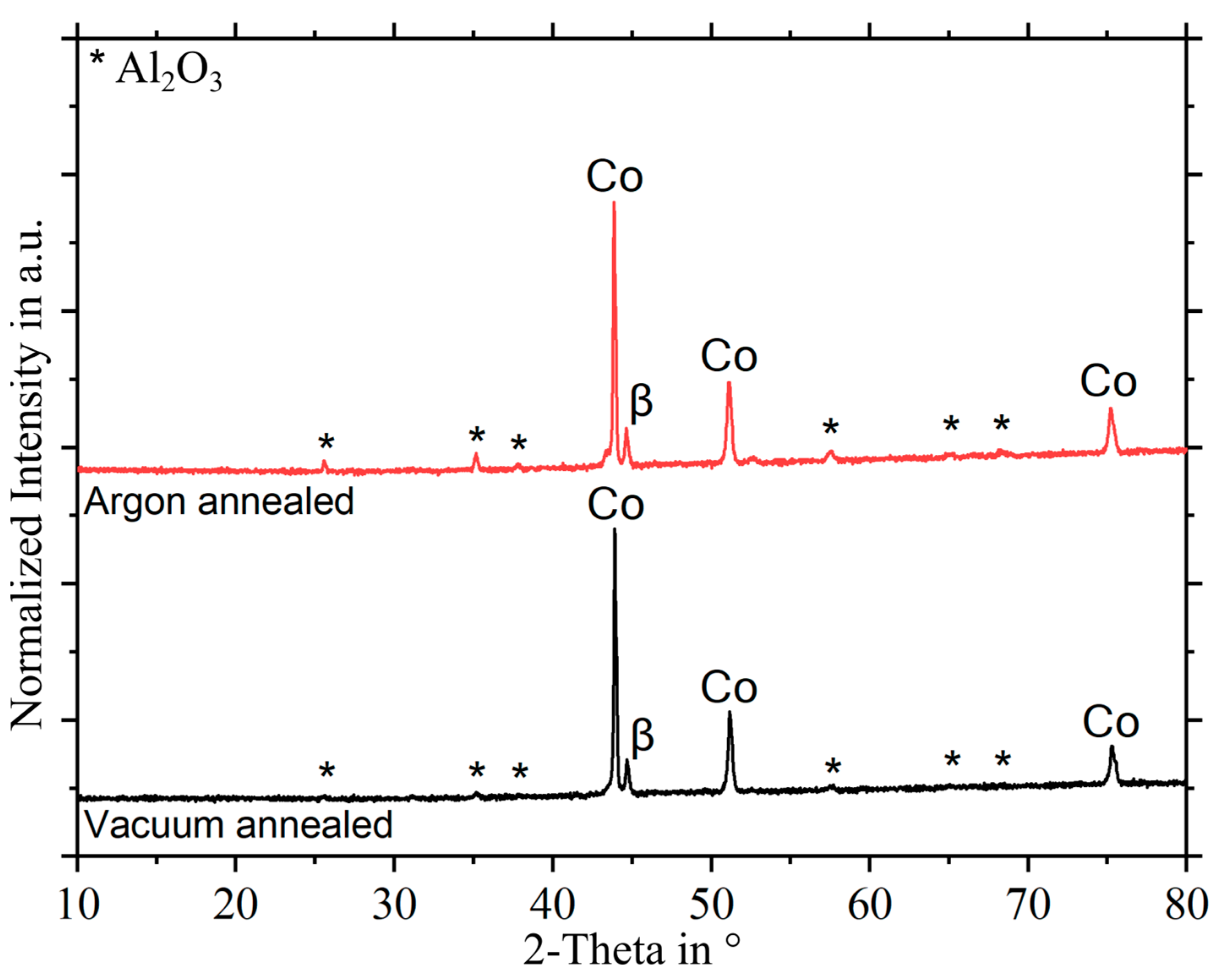
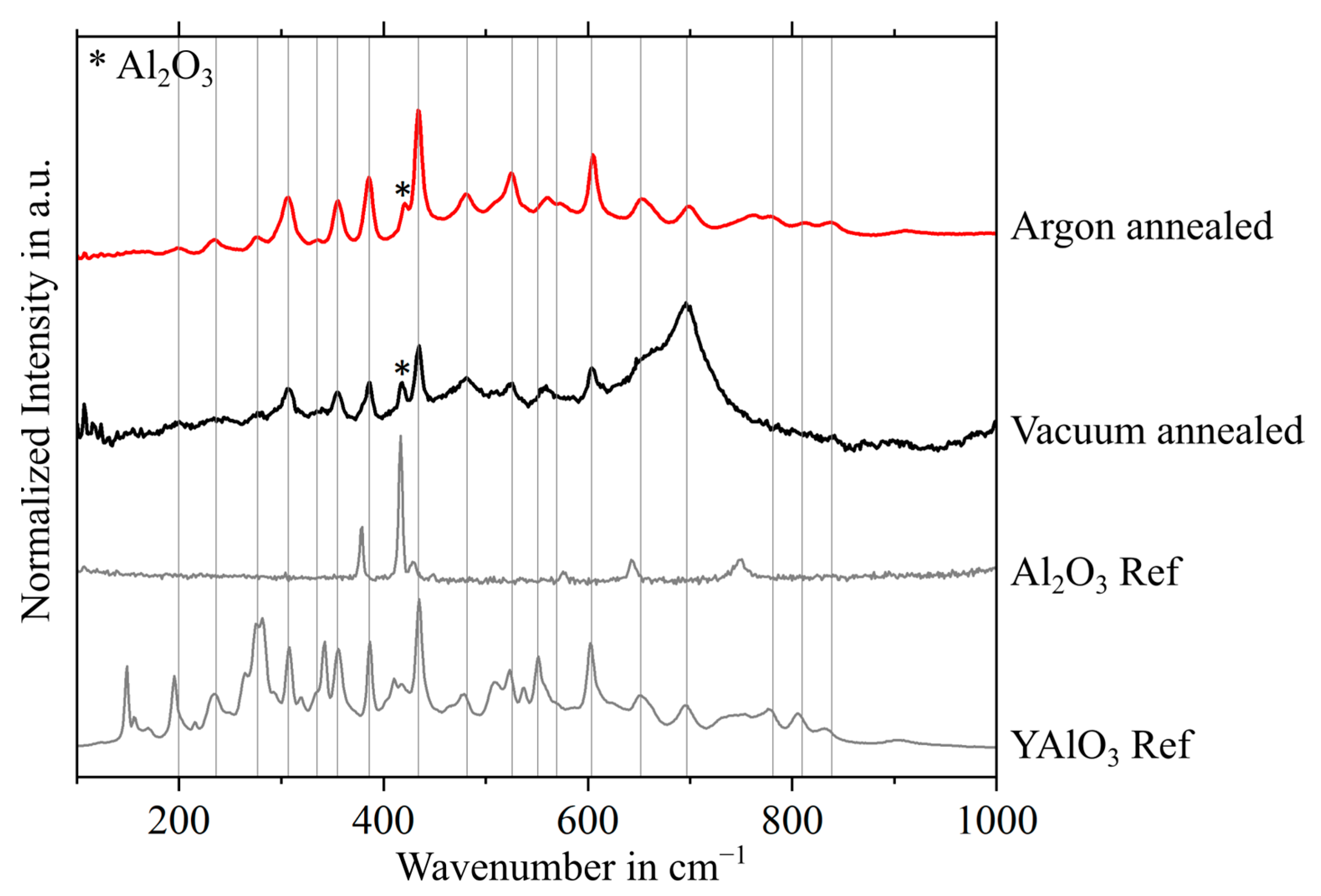
3.2. Phase Characterization of Oxides Formed during Heat Treatment

For further analysis of the oxide layers formed, phases were determined on the bond coat surfaces using XRD and Raman spectroscopy. For this purpose, the heat-treated specimens were examined before the ceramic top layer was applied. In the evaluation, it is assumed that any oxidation observed was caused by heat treatment in a vacuum or argon atmosphere. The reason for this is that the studies by Matsumoto et al. and Joeris et al. using XRD and/or Raman spectroscopy have shown that CoNiCrAlY coatings are still oxide-free after vacuum plasma spraying [14,19].
In the XRD analysis (Figure 2), the main peaks appeared at a 2-θ angle of about 44° for all bond coat surfaces. Since the bond coat alloy has a high Co and Ni content, it is expected that the peaks of Co (2-θ angles of 43.9, 51.1 and 75.1°) and Ni (44.6, 51.3 and 76.0°) partially overlap there. However, the peak at 75.1° indicates that Co is the main phase measured at the surface. This is due to the low thickness of the oxide layer, as the method also detects deeper areas than the TGO thicknesses. The Ni peak next to the main phase can also be identified as the β phase [14]. However, in addition to the peaks of the main components of the alloy, other peaks can be identified, all of which can be assigned to the Al2O3 phase. This finding is consistent with the SEM images shown previously in Figure 1, as the peaks of this phase are also stronger on the argon-annealed bond coats, indicating a thicker Al2O3 layer. These results are in good agreement with those of the previous studies mentioned [14,19].
Raman spectroscopy was also used for further detailed analysis of the oxide layer on the bond coat surface after diffusion annealing. The advantage of this method is the very low intensity or even absence of signals in metals. This allows a more detailed investigation of the grown oxides. The spectra measured by Raman spectroscopy are shown in Figure 3 and can be assigned to the colors of the XRD spectra in Figure 2. In addition, reference measurements of yttrium aluminum oxide (YAlO3) and Al2O3 powder are shown. It is important to note that all measurement curves shown in Figure 3 have been normalized so the recorded signal intensities are not comparable. This has been carried out to ensure that the peaks that occur in all the graphs are clearly visible.
Similar to the reports by Vande Put et al. [27] and Joeris et al. [19], most of the peaks can be assigned to the YAlO3 phase [28]. The peaks of this phase are almost identical in intensity and shape to those of the reference measurement. The deviations could be due to an artifact of additional elements in the bond coat, such as Co, Ni, and Cr, which could affect the YAlO3 structure. In addition, the differences could be due to variations in the surface topography, which can cause autofocus artifacts during the measurement. In addition to YAlO3, the specimens also show a signal of Al2O3 at 418 cm−1 [29]. It should be noted that Al2O3 was also measured in previous reports [19], where it was shown that the Al2O3 has a much lower signal intensity (about 16 times lower) compared to YAlO3. Therefore, it is possible that even low concentrations of YAlO3 show more intense signals compared to Al2O3. The low concentration of YAlO3 can be assumed as only small grains were identified in the SEM images and the signal remained below the detection limit in the XRD measurements. However, peaks of undesirable mixed oxides such as Co3O4, Cr2O3, or NiO, which have been detected in other studies [30], could not be detected.
Combining the results of the SEM images, XRD measurements and Raman spectroscopy, it can be concluded that no unwanted mixed oxides were formed during the heat-treatments. In addition, the desired Al2O3 layer was predominantly formed, which is clearly evident from the SEM images and XRD measurements. This layer was continuous in the argon pre-oxidized specimens and should therefore contribute to a slowly growing oxide layer. Furthermore, the presence of yttrium–aluminum oxide grains in the TGO was confirmed by SEM images and Raman spectroscopy.

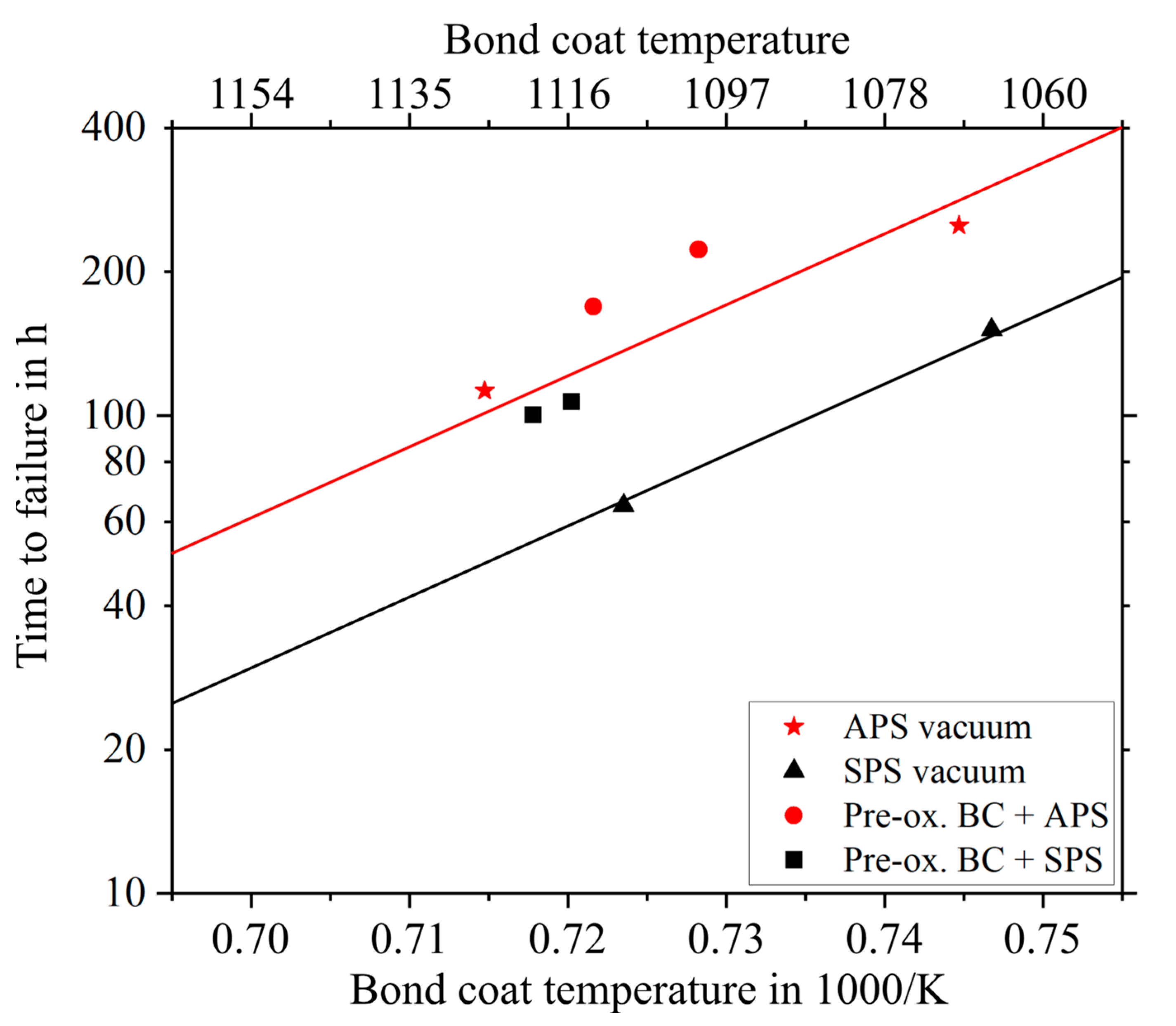
3.3. Burner Rig Cycling Tests

Figure 4 shows the results of the thermal gradient cycling tests in the burner rig. To compare the performance of the different coating systems during the thermal cycling tests, the specimens were evaluated based on the number of cycles completed without failure and the average logged bond coat temperature. There is a linear relationship between the logarithmic time to failure and the inverse of the bond coat temperature for the failure of TBC systems due to the Arrhenius-type behavior of the TGO growth rate [11]. Reducing the bond coat temperature by 30 °C doubles the time to failure, as shown in Figure 4 by the black and red lines for the SPS and APS systems with the vacuum-treated bond coat. To determine the lifetime, only the heating time of each cycle was calculated, i.e., 5 min was added to the lifetime for each cycle completed.
The cycling results in Figure 4 show that the lifetime of the coatings with the APS topcoat and the vacuum-annealed bond coat (red line) significantly exceeds that of the SPS coatings on this bond coat (black line). Considering the results of the systems with the bond coats pre-oxidized in an argon atmosphere, the lifetimes are more similar. However, it should be noted that both the APS and SPS topcoat systems showed an improvement in lifetime as a result of pre-oxidation. To understand why the improvement in service life was particularly pronounced in the SPS topcoated systems, the SEM cross sections of the cycling buttons after failure were also examined.
The overview images of the failed specimens with a vacuum-treated bond coat in Figure 5 show a different failure mode between the APS and SPS topcoats, which was also observed in case of the argon heat-treated specimens. The APS coatings failed predominantly at the interface between the ceramic topcoat and the metallic bond coat. This indicates the weakest cohesion in the TGO itself or weakest adhesion of the ceramic to the TGO. Thus, the elastic energy stored in the porous APS coatings does not exceed the critical energy release rate of the coating. However, fine cracks also formed in the ceramic coating near the interface between splats, which also exhibited low adhesion. Before these cracks in the ceramic lead to a sufficiently low level of the critical energy release rate, the cracks grow along or within the TGO.
The SPS topcoat systems, on the other hand, show the crack leading to failure within the ceramic topcoat near the interface. These cracks run along the roughness peaks of the bond coat. However, they do not follow the interface and the TGO, but propagate within the porosity bands of the coating. It is assumed that the cracks form above the roughness peaks in the interface or in the ceramic near the interface due to the radial stresses created by the expansion difference between the bond and topcoats during thermal cycling. From there, the cracks propagate along the porosity bands in which the bonding is low. Therefore, the SPS coatings failed in the first or second porosity band.
The oxide layers formed during thermal cycling are shown at high magnification in Figure 6. The measured TGO thicknesses are listed in Table 4. Both show that the oxide scale thicknesses do not differ significantly. The SEM images also show that only a few mixed oxides were formed. The longer life of the coating systems can therefore be attributed to the slower growth of the TGO after pre-oxidation. Partial depletion of the Al-rich β-phase in the bond coat was observed in the pre-oxidized specimens and in the vacuum-annealed specimens with the APS topcoat. Mixed oxides formed at these locations, causing the specimen to fail. In contrast, in the specimen with the vacuum-treated bond coat and SPS topcoat, a thin band of aluminum-rich β phase remained at each point of the specimen. Here, the failure occurred due to the elastic energy stored in the topcoat. However, no significant difference in TGO thickness was observed as the β phase was also almost completely depleted. It is assumed that the initial rapid oxide growth during thermal cycling introduced high stresses with early arching the top layer, promoting the early crack propagation in the ceramic layer and its failure.
In the case of the APS coatings, the slowed oxide growth due to pre-oxidation only slightly extended the life of the coatings, as critical stresses which create initial delamination cracks within the TGO only occur after considerable TGO evolution and mixed oxide formation. For the SPS coatings, however, it is assumed that the formation of the TGO prior to the application of the ceramic topcoat was able to change the stress distribution within the coating system. Since the initial rapid growth rates of the oxide layer were completed mainly before the application of the topcoat, they did not affect the ceramic topcoat during thermal cycling. As a result, the specimens failed only when partial aluminum depletion occurred in the bond coat. However, the adhesion between the individual ceramic layers of the SPS coating was worse compared to the TGO layer and the APS layer. Therefore, the specimens failed in the topcoat and not at the interface. Therefore, the lifetimes of the APS films with pre-oxidized bond coat are also longer than those of the SPS topcoats, as they only fail in or along the TGO. The SPS films, in contrast, failed before this fracture occurred at the TGO. This failure mode differs from the results of the study by Joeris et al. on the pre-oxidation of TBCs with an SPS topcoat. There, the pre-oxidation also shifted the failure location to the TGO [19]. It should therefore be investigated whether the topcoat is not sufficiently optimized for thermal cycling or whether the pre-oxidation can be further adapted for the coating system under consideration to create ideal conditions for thermal cycling.

4. Conclusions

This study investigated whether the pre-oxidation of a CoNiCrAlY bond coat has a different effect on the thermal cyclability of specimens with different thermal sprayed topcoats. Pre-oxidizing the bond coat increased the service life of both the coating systems with an APS and the SPS topcoat. The dense Al2O3 oxide layer grown in an argon atmosphere was able to slow down subsequent oxidation during thermal cycling and thus contribute to improved cyclability. As a result, a doubling of the service life could be achieved for coating systems with an SPS topcoat applied to a pre-oxidized bond coat, compared to specimens that had a bond coat heat treated in a vacuum. After pre-oxidation, the specimens lasted until the bond coat was partially depleted of the Al-rich β phase and mixed oxides were formed. Nevertheless, the overall lifetime of the cycling buttons with an APS top layer was higher. This is due to the fact that the SPS coatings failed in the ceramic top layer near the interface. In contrast, the APS coating systems were able to withstand the growth stresses of the alumina scale and mixed oxides as well as the loads during thermal cycling, until failure occurred within the TGO. It is assumed that the elastically stored energy in the SPS coating is primarily present close to the interface. There it exceeds the critical energy release rate of the interpass porosity bands with their low adhesion. All in all, the oxide growth showed a decisive influence on the performance in thermal cycling, especially for the SPS coatings.

Author Contributions

Conceptualization, J.I. and R.V.; methodology J.I. and R.V.; investigation, J.I. and W.S.S.; writing—original draft preparation, J.I.; writing—review and editing, W.S.S., D.E.M., O.G. and R.V.; visualization, J.I. and W.S.S. All authors have read and agreed to the published version of the manuscript.

Funding

This work is part of the LaBeGa project, which was funded by the Federal Ministry of Economic Affairs and Climate Action (BMWK), Germany, within the framework of the 7th Energy Research Program (FKZ 03EE5045A).

Institutional Review Board Statement

Not applicable.

Informed Consent Statement

Not applicable.

Data Availability Statement

The original contributions presented in the study are included in the article, further inquiries can be directed to the corresponding author.

Acknowledgments

The authors would like to thank the project partners Oerlikon Metco WOKA GmbH for providing materials. In addition, the authors would like to thank the following employees of the institute for their support: Karl-Heinz Rauwald, Frank Kurze, and Ralf Laufs for the production of the coatings and Martin Tandler for his support regarding the furnace cycling tests, Doris Sebold for some of the SEM images and Yannic Collette for his support with the Raman measurements.

Conflicts of Interest

The authors declare no conflicts of interest.

References

  1. Arnault, V.; Mévrel, R.; Alpérine, S.; Jaslier, Y. Thermal barrier coatings for aircraft turbine airfoils thermal challenge and materials. Rev. Met. 1999, 96, 585–597. [Google Scholar] [CrossRef]
  2. Padture, N.P.; Gell, M.; Jordan, E.H. Thermal barrier coatings for gas-turbine engine applications. Science 2002, 296, 280–284. [Google Scholar] [CrossRef] [PubMed]
  3. Wellman, R.G.; Deakin, M.J.; Nicholls, J.R. The effect of TBC morphology on the erosion rate of EB PVD TBCs. Wear 2005, 258, 349–356. [Google Scholar] [CrossRef]
  4. Jones, R.L. Some Aspects of the Hot Corrosion of Thermal Barrier Coatings. Therm. Spray Technol. 1997, 6, 77–84. [Google Scholar] [CrossRef]
  5. Krämer, S.; Yang, J.; Levi, C.G.; Johnson, C.A. Thermochemical Interaction of Thermal Barrier Coatings with Molten CaO–MgO–Al2O3–SiO2 (CMAS) Deposits. J. Am. Ceram. Soc. 2006, 89, 3167–3175. [Google Scholar] [CrossRef]
  6. Rabiei, A. Failure mechanisms associated with the thermally grown oxide in plasma-sprayed thermal barrier coatings. Acta Mater. 2000, 48, 3963–3976. [Google Scholar] [CrossRef]
  7. Thompson, J.A.; Clyne, T.W. The Stiffness of Plasma Sprayed Zirconia Top Coats in TBCs. In Proceedings of the UTSC 1999, UTSC’99, Dusseldorf, Germany, 17–19 March 1999. [Google Scholar]
  8. Scott, H.G. Phase relationships in the zirconia-yttria system. J. Mater. Sci. 1975, 10, 1527–1535. [Google Scholar] [CrossRef]
  9. Chang, G.C.; Phucharoen, W.; Miller, R.A. Behavior of thermal barrier coatings for advanced gas turbine blades. Surf. Coat. Technol. 1987, 30, 13–28. [Google Scholar] [CrossRef]
  10. Traeger, F.; Ahrens, M.; Vaßen, R.; Stöver, D. A life time model for ceramic thermal barrier coatings. Mater. Sci. Eng. A 2003, 358, 255–265. [Google Scholar] [CrossRef]
  11. Vaßen, R.; Giesen, S.; Stöver, D. Lifetime of Plasma-Sprayed Thermal Barrier Coatings: Comparison of Numerical and Experimental Results. J. Therm. Spray Technol. 2009, 18, 835–845. [Google Scholar] [CrossRef]
  12. Niranatlumpong, P.; Ponton, C.B.; Evans, H.E. The Failure of Protective Oxides on Plasma-Sprayed NiCrAlY Overlay Coatings. Oxid. Met. 2000, 53, 241–258. [Google Scholar] [CrossRef]
  13. Chang, W.L.E.; Wu, B.C.; Chao, C.H. Effects of bond coat preoxidation on the properties of ZrO2-8wt.% Y2O3/Ni-22Cr-10Al-1Y thermal-barrier coatings. Oxid. Met. 1991, 36, 221–238. [Google Scholar] [CrossRef]
  14. Matsumoto, M.; Hayakawa, K.; Kitaoka, S.; Matsubara, H.; Takayama, H.; Kagiya, Y.; Sugita, Y. The effect of preoxidation atmosphere on oxidation behavior and thermal cycle life of thermal barrier coatings. Mater. Sci. Eng. A 2006, 441, 119–125. [Google Scholar] [CrossRef]
  15. Tolpygo, V.K.; Clarke, D.R.; Murphy, K.S. The effect of grit blasting on the oxidation behavior of a platinum-modified nickel-aluminide coating. Met. Mater. Trans. A 2001, 32, 1467–1478. [Google Scholar] [CrossRef]
  16. Prescott, R.; Graham, M.J. The formation of aluminum oxide scales on high-temperature alloys. Oxid. Met. 1992, 38, 233–254. [Google Scholar] [CrossRef]
  17. Nijdam, T.J.; Sloof, W.G. Combined pre-annealing and pre-oxidation treatment for the processing of thermal barrier coatings on NiCoCrAlY bond coatings. Surf. Coat. Technol. 2006, 201, 3894–3900. [Google Scholar] [CrossRef]
  18. Kitaoka, S.; Kuroyama, T.; Matsumoto, M.; Kitazawa, R.; Kagawa, Y. Control of polymorphism in Al2O3 scale formed by oxidation of alumina-forming alloys. Corros. Sci. 2010, 52, 429–434. [Google Scholar] [CrossRef]
  19. Joeris, J.; Scheld, W.S.; Uhlenbruck, S.; Sohn, Y.J.; Sebold, D.; Guillon, O.; Vaßen, R. Preparation of Highly Durable Columnar Suspension Plasma Spray (SPS) Coatings by Pre-Oxidation of the CoNiCrAlY Bondcoat. Coatings 2023, 13, 1575. [Google Scholar] [CrossRef]
  20. Zhou, D.; Guillon, O.; Vaßen, R. Development of YSZ Thermal Barrier Coatings Using Axial Suspension Plasma Spraying. Coatings 2017, 7, 120. [Google Scholar] [CrossRef]
  21. Negami, M.; Hibino, S.; Kawano, A.; Nomura, Y.; Tanaka, R.; Igashira, K. Development of Highly Durable Thermal Barrier Coating by Suppression of Thermally Grown Oxide. J. Eng. Gas Turbines Power 2018, 140, 082101. [Google Scholar] [CrossRef]
  22. Negami, M.; Kyuma, K.; Azuma, M.; Taniguchi, T.; Yamabe-Mitarai, Y. Improvement of the durability of thermal barrier coating by pre-oxidation. Corros. Sci. 2024, 227, 111806. [Google Scholar] [CrossRef]
  23. Negami, M.; Yamabe-Mitarai, Y. The Oxidation Behaviors of NiCoCrAlY Coatings After Pre-Oxidation Treatment During High-Temperature Oxidation at 800 °C and 900 °C. High Temp. Corros. Mater 2024, 101, 511–527. [Google Scholar] [CrossRef]
  24. Igel, J.; Mauer, G.; Guillon, O.; Vaßen, R. Systematic Approach to Optimize Technological and Economical Aspects of Atmospheric Plasma Sprayed Thermal Barrier Coatings. Adv. Eng. Mater. 2023, 26, 2300623. [Google Scholar] [CrossRef]
  25. Traeger, F.; Vaßen, R.; Rauwald, K.-H.; Stöver, D. Thermal Cycling Setup for Testing Thermal Barrier Coatings. Adv. Eng. Mater. 2003, 5, 429–432. [Google Scholar] [CrossRef]
  26. Nowak, W.; Naumenko, D.; Mor, G.; Mor, F.; Mack, D.E.; Vassen, R.; Singheiser, L.; Quadakkers, W. Effect of processing parameters on MCrAlY bondcoat roughness and lifetime of APS–TBC systems. Surf. Coat. Technol. 2014, 260, 82–89. [Google Scholar] [CrossRef]
  27. Vande Put, A.; Oquab, D.; Péré, E.; Raffaitin, A.; Monceau, D. Beneficial Effect of Pt and of Pre-Oxidation on the Oxidation Behaviour of an NiCoCrAlYTa Bond-Coating for Thermal Barrier Coating Systems. Oxid. Met. 2011, 75, 247–279. [Google Scholar] [CrossRef]
  28. Hernández-Rodríguez, M.A.; Monteseguro, V.; Lozano-Gorrín, A.D.; Manjón, F.J.; González-Platas, J.; Rodríguez-Hernández, P.; Muñoz, A.; Lavín, V.; Martín, I.R.; Rodríguez-Mendoza, U.R. Structural, Vibrational, and Elastic Properties of Yttrium Orthoaluminate Nanoperovskite at High Pressures. J. Phys. Chem. C 2017, 121, 15353–15367. [Google Scholar] [CrossRef]
  29. Thapa, J.; Liu, B.; Woodruff, S.D.; Chorpening, B.T.; Buric, M.P. Raman scattering in single-crystal sapphire at elevated temperatures. Appl. Opt. 2017, 56, 8598–8606. [Google Scholar] [CrossRef] [PubMed]
  30. Bolelli, G.; Vorkötter, C.; Lusvarghi, L.; Morelli, S.; Testa, V.; Vaßen, R. Performance of wear resistant MCrAlY coatings with oxide dispersion strengthening. Wear 2020, 444–445, 203116. [Google Scholar] [CrossRef]
Figure 1. SEM images of the interfaces of the four different coating systems investigated after diffusion annealing in different atmospheres and topcoat application by different processes: (a) APSv, (b) SPSv, (c) APSpre-ox., (d) SPSpre-ox.
Coatings 14 00793 g001
Figure 2. XRD measurements of the vacuum-annealed bond coat (black) and the bond coat annealed in an argon atmosphere (red) in the 2-θ range from 10 to 80°.
Coatings 14 00793 g002
Figure 3. Raman spectra (all normalized) of a YAlO3 and Al2O3 reference measurements (gray lines) from [19] as well as the spectra of the bond coat heat treated in a vacuum in black and the bond coat heat treated in argon in red.
Coatings 14 00793 g003
Figure 4. Arrhenius plot of the service life until failure as a function of the inverse bond coat temperature for the different YSZ-TBCs: APS systems in red, SPS systems in black; lines indicate the average service life of respective coating system with a bond coat annealed in a vacuum.
Coatings 14 00793 g004
Figure 5. SEM overview images of the failed specimens with bond coat treated in vacuum: (a) APSv, (b) SPSv.
Coatings 14 00793 g005
Figure 6. SEM cross-sections of failed specimens of each coating system: (a) APSv, (b) SPSv, (c) APSpre-ox, (d) SPSpre-ox.
Coatings 14 00793 g006
Table 1. Chemical composition of different topcoat materials in wt.-% according to data sheet; * Maximum amount included in ZrO2.
Chemical Composition in wt.-%Particle Size Distribution in µm
MetcoZrO2HfO2 *Y2O3SiO2TiO2Al2O3Fe2O3Othersd10d50d90
233CBal.<2.07.0–9.0<0.5<0.2<0.2<0.2<0.857.877.2101.9
6608Bal<2.57.0–8.0<0.05<0.05<0.05<0.05-0.41.54.9FZJ
Table 2. Nomenclature of the various coating systems in combination with the bond coat heat treatment and topcoat system used, as well as parameters for the production of the topcoat; * Feed rate solids content.
Plasma GasesPowderStandoff
SpecimenBC Heat TreatmentTopcoatCurrentArH2Feed RateDistanceRobot SpeedStep Size
[A][nlpm][nlpm][g/min][mm][mm/s][mm]
APSvVacuumAPS411526.210016110004
SPSvVacuumSPS55064812 *7010002
APSpre-ox.ArgonAPS411526.210016110004
SPSpre-ox.ArgonSPS55064812 *7010002
Table 3. TGO thicknesses and roughness values of the bond coats with different heat treatments.
BC Heat TreatmentTGO ThicknessRaRz
[µm][µm][µm]
Vacuum0.1–0.3 (partially no oxide layer)7.0 ± 0.649.8 ± 2.8
Argon0.8 ± 0.28.3 ± 0.760.4 ± 5.0
Table 4. TGO thickness after thermal cycling failure of the various coating systems tested.
SpecimenTGO Thickness
[µm]
APSv3.9 ± 0.8
SPSv3.6 ± 0.8
APSpre-ox.3.2 ± 1.0
SPSpre-ox.3.3 ± 0.6
Disclaimer/Publisher’s Note: The statements, opinions and data contained in all publications are solely those of the individual author(s) and contributor(s) and not of MDPI and/or the editor(s). MDPI and/or the editor(s) disclaim responsibility for any injury to people or property resulting from any ideas, methods, instructions or products referred to in the content.

