Article

Stable N-Type Single-Walled Carbon Nanotube/Mesh Sheets by Cationic Surfactant Doping and Fluoropolymer Coating for Flexible Thermoelectric Generators

Department of Materials Science, Tokai University, 4-1-1 Kitakaname, Hiratsuka 259-1292, Kanagawa, Japan
*
Author to whom correspondence should be addressed.
Coatings 2024, 14(7), 794; https://doi.org/10.3390/coatings14070794
Submission received: 31 May 2024 / Revised: 21 June 2024 / Accepted: 22 June 2024 / Published: 26 June 2024
(This article belongs to the Special Issue Thermoelectric Materials for Sustainable Applications)

Abstract

:
Single-walled carbon nanotubes (SWCNTs) offer promise as materials for thermoelectric generators (TEGs) due to their flexibility, durability, and non-toxic nature. However, a key barrier to their application lies in their high thermal conductivity, which hampers the generation of temperature differences in TEGs. To address this challenge, we explored a method of enhancing the heat dissipation of SWCNT-based TEGs by coating SWCNT layers onto polymer mesh sheets. During TEG fabrication, achieving stable n-type SWCNT/mesh sheets proved considerably more challenging than their p-type counterparts. This difficulty stemmed from the inferior dispersibility of the n-type SWCNT ink compared to the p-type SWCNT ink. To produce n-type SWCNT/mesh sheets, we initially prepared p-type SWCNT/mesh sheets using p-type SWCNT ink, subsequently doping them with a cationic surfactant solution to induce n-type characteristics. To stabilize the n-type thermoelectric properties in SWCNT/mesh sheets, we applied a fluoropolymer coating to the SWCNT surfaces, mitigating the adsorption of oxygen molecules. This approach yielded n-type SWCNT/mesh sheets capable of long-term maintenance. Furthermore, flexible TEGs fabricated using both p- and n-type SWCNT/mesh sheets demonstrated an output voltage of 15 mV, which can operate IoT sensors using the latest booster circuits, and a maximum power of 100 nW at a temperature difference of 71 K.

1. Introduction

In recent years, flexible thermoelectric generators (FTEGs) have emerged as a promising technology for recovering waste heat in low-power consumption applications such as sensors and wearable health monitoring devices [1,2,3,4,5,6,7]. FTEGs consist of thermoelectric films with both p- and n-type properties formed on flexible substrates. Electricity is generated by establishing temperature differences between both ends of the thermoelectric films. The efficiency of thermoelectric generators directly correlates with the physical properties of the thermoelectric films, including the electrical conductivity, Seebeck coefficient, and thermal conductivity. High-performance thermoelectric films exhibit a high electrical conductivity and Seebeck coefficient while demonstrating low thermal conductivity. The primary thermoelectric materials are bismuth telluride-based alloys, as they offer a high performance near room temperature, where low-power consumption applications are predominantly utilized [8,9,10,11,12]. However, these alloys face limitations due to tellurium’s toxicity and scarcity, as well as the uneven distribution of bismuth resources. Additionally, these alloys are fragile and lack sufficient flexibility. Therefore, there is a pressing need to develop flexible thermoelectric materials composed of elements that are non-toxic and abundant in resources.
The most favorable thermoelectric materials meeting the aforementioned requirements are single-walled carbon nanotubes (SWCNTs) [13,14,15,16,17]. SWCNTs are hollow cylindrical structures composed of rolled graphene sheets [18]. The structure of SWCNTs is defined by the chiral index (n, m), which contains information about the direction of the roll of the graphene sheet and determines whether the SWCNTs have metallic or semiconducting properties [19,20,21,22]. Metallic SWCNTs are utilized as composite materials with rubber, resin, and metal [23], while semiconducting SWCNTs are increasingly employed in electronic devices for applications such as transistors, memories, and sensors [24,25,26,27]. Thus, FTEGs utilize semiconducting SWCNTs [28,29].
While SWCNTs offer excellent properties for FTEGs, a significant challenge must be addressed: their higher thermal conductivity compared to typical inorganic thermoelectric materials. Individual SWCNTs exhibit an extraordinarily high thermal conductivity at room temperature, calculated through molecular dynamics simulations to be 6600 W/(m·K) [30]. However, when numerous individual SWCNTs are assembled into a bundle and formed into a film, the thermal conductivity is significantly reduced, with in-plane values ranging from 5 to 42 W/(m·K), attributed to the interfacial thermal resistance between the SWCNTs [31,32,33,34]. Nevertheless, these values still exceed those of inorganic thermoelectric materials [35,36,37,38,39]. To further reduce the thermal conductivity of SWCNT films without compromising the overall thermoelectric performance, one approach is to form nanocomposites with SWCNTs and thermoelectric organic polymers [40,41,42,43]. Another approach, as outlined in our previous report, involves coating SWCNT layers onto polymer mesh (SWCNT/mesh) sheets while maintaining the mesh opening to decrease the thermal conductivity of the SWCNT films [44]. In this fabrication process, an SWCNT ink containing an anionic surfactant as a p-type dopant was prepared, and the meshes were dipped into the ink. The resulting p-type SWCNT/mesh sheets exhibited a relatively large temperature difference compared to standard SWCNT films without openings.
The subsequent task involves fabricating the n-type SWCNT/mesh sheets, which presents a significant challenge in maintaining long-term thermoelectric properties. Various n-type doping techniques have been employed in standard SWCNT films, yielding excellent results [45,46,47,48,49,50,51]. In our prior study, we prepared an SWCNT ink containing a cationic surfactant as an n-type dopant, achieving n-type SWCNT films with exceptional air stability (over two years) via drop casting [52]. Hence, we endeavor to develop n-type SWCNT/mesh sheets with enduring thermoelectric properties, aiming to enhance the performance of FTEGs utilizing both p- and n-type SWCNT/mesh sheets. Due to the lower dispersibility of n-type SWCNT inks compared to their p-type counterparts [53], coating the mesh surface with SWCNTs proves challenging, as depicted in the Supplementary Information (Figure S1). Consequently, we initially prepared p-type SWCNT/mesh sheets using the p-type SWCNT ink and subsequently conducted n-type doping using a cationic surfactant solution. Additionally, to stabilize the n-type thermoelectric properties in SWCNT/mesh sheets, we applied a fluoropolymer coating to the SWCNT surfaces to prevent the adsorption of water and oxygen molecules.

2. Materials and Methods

Figure 1 illustrates the manufacturing process of the SWCNT/mesh sheets, which builds upon previous reports [44,54]. The starting materials, SWCNTs synthesized using the super-growth method (SG-CNTs) (ZEONANO SG101, Kawasaki, Japan), and SWCNT inks were supplied by ZEON Corporation [55]. The SWCNT inks were mixed with SWCNT powders, an anionic surfactant, sodium dodecylbenzene sulfate (SDBS) (Tokyo Chemical Industry, Chuo-ku, Tokyo, Japan), and deionized water, resulting in a concentration of 0.2 wt% SWCNT and 0.5 wt% SDBS. To enhance the viscosity of the SWCNT inks, the mixture was heated on a hot plate, gradually increasing from room temperature to 80 °C while gently stirring to evaporate the water. Consequently, a high-viscosity SWCNT ink was obtained at a concentration of 0.4 wt% SWCNT and 1.0 wt% SDBS.
The mesh utilized in this study was constructed from polyphenylene sulfide (PPS) with a sieve featuring 100 μm aperture and 34 μm wire diameter (Clever Co., Toyohashi, Japan). SWCNT/mesh sheets were prepared by immersing the PPS mesh in the high-viscosity SWCNT ink, followed by drying at 60 °C for 24 h. To vary the thickness of the SWCNT layer, we created two samples by dipping the meshes once and twice in the SWCNT ink. It’s worth noting that the SWCNT/mesh sheets at this stage exhibited p-type thermoelectric properties [51]. To convert the thermoelectric properties to n-type, we utilized the cationic surfactant dimethyldioctadecylammonium chloride (DODMAC) (Fujifilm Wako Pure Chemical, Osaka, Japan) as an n-type dopant [52]. The n-type dopant solution was prepared by adding 1.0 g of DODMAC to 50 mL of ethanol and dispersing it using an ultrasonic homogenizer (Branson Sonifier SFX 250, Emerson, St. Louis, MO, USA) operating for 60 min at a maximum power of 200 W and an amplitude of 70%. The SWCNT/mesh sheets were immersed in the n-type dopant solution, followed by thermal treatment using an electric furnace. The thermal treatment temperature was set at 150 °C in a mixture of argon (95%) and hydrogen (5%) gases at atmospheric pressure, with a treatment duration of 1 h. To sustain n-type properties with extended air stability, a fluoropolymer (Superhydrophobic, FK, Nishinomiya, Japan) was sprayed on both surfaces of the SWCNT/mesh sheets for approximately 5 s on each side. To characterize the SWCNT/mesh sheets at each stage of the manufacturing process, we designated the samples as shown in Table 1. In addition, the average thickness including the PPS mesh sheet of all samples is added to this table. Samples A-1 and A-2 were pristine SWCNT/mesh sheets coated with the SWCNT ink on the PPS mesh surface. The numbers at the end of the sample names indicate the number of dips. Samples B-1 and B-2 were dipped into the DODMAC solution, following the treatment of Samples A-1 and A-2, respectively, followed by heat treatment. Samples C-1 and C-2 were sprayed with fluoropolymer following the treatment of Samples B-1 and B-2, respectively. When the fluoropolymer was coated on the surface, organic solvents containing fluoropolymers covered the surface, and the only organic solvents were evaporated after approximately 5 min. The thickness depends on the number of SWCNT dips, but not on the DODMAC dipping or polymer spraying processes. The microstructure and morphologies of the SWCNT/mesh sheets at each stage (following SWCNT ink dipping, n-type dopant solution dipping, and fluoropolymer spraying) were analyzed using field emission scanning electron (FE-SEM, Hitachi, S-4800, Hitachi, Japan) at an accelerating voltage of 3 kV. The chemical structures of the SWCNT/mesh sheets after fluoropolymer spraying were characterized by XPS (ULVAC-PHI Quantum 2000, Chigasaki, Japan) using Al Kα irradiation.
The in-plane Seebeck coefficient S of the SWCNT/mesh sheets at each stage was measured with an accuracy of ±10% at a temperature of approximately 25 °C [2]. One end of the film was connected to a heat sink, while the other end was connected to a heater. The Seebeck coefficient was calculated by determining the ratio of the potential difference along the SWCNT/mesh sheets to the temperature difference, measured using two K-type thermocouples pressed against the surface of the SWCNT/mesh sheet. The in-plane electrical conductivity σ of the SWCNT/mesh sheets was measured at an approximate temperature of 25 °C using a four-point probe method (Napson, RT-70V, Koto-ku, Tokyo, Japan) with an accuracy of ±10%. The in-plane power factor PF an important parameter for determining thermoelectric performance, was evaluated using the equation PF = σS2. To assess the time dependence of the Seebeck coefficient of the SWCNT/mesh sheets, measurements were taken at 1-week intervals over a total of 15 weeks.

3. Results and Discussion

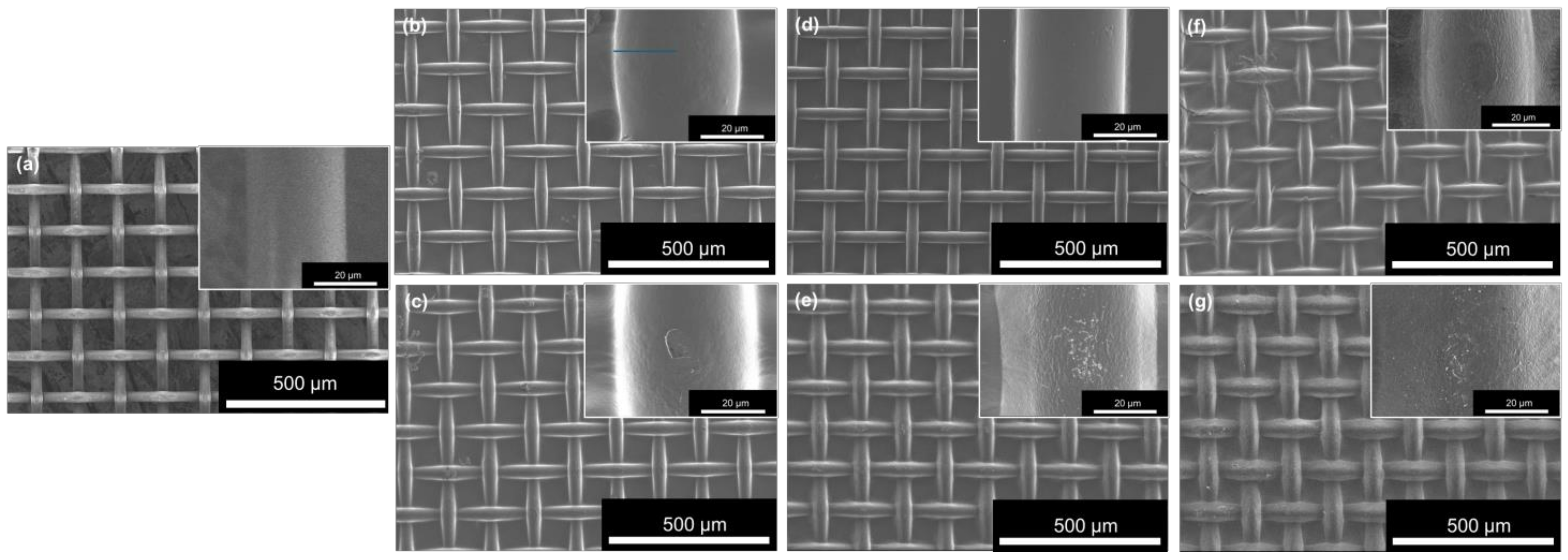
3.1. Structural Properties of SWCNT/Mesh Sheets

Figure 2 illustrates SEM images of SWCNT/mesh sheets at different stages of the manufacturing process. Figure 2a displays the PPS mesh sheet before SWCNT dip coating, revealing a uniform mesh aperture (100 μm) and wire diameter (34 μm) throughout the sheet. In Figure 2b, corresponding to Sample A-1 presented in Table 1, the wire diameter increased compared to Figure 2a due to the formation of the SWCNT layer on the PPS mesh surface from a single dip. The inset provides an enlarged view of one wire, showing a significantly smoother SWCNT layer surface. The estimated wire diameter was approximately 40 μm, indicating a deposited SWCNT layer thickness of around 3 μm on the PPS mesh. Upon performing a double SWCNT dip (Sample A-2), shown in Figure 2c, the wire diameter further increased compared to Sample A-1. Although the surface smoothness slightly decreased compared to Sample A-1, the inset reveals no significant change. The estimated wire diameter was approximately 46 μm, indicating a deposited SWCNT layer thickness of around 6 μm on the PPS mesh. Despite the increased amount of SWCNTs on the mesh with more dip coatings, the mesh openings remained unfilled with SWCNTs. Figure 2d,e depict SWCNT/mesh sheets dipped into the DODMAC solution followed by heat treatment, showing minimal change in mesh structures and morphologies. However, Figure 2e reveals small particles scattered on the SWCNT surface, derived from crystallized DODMAC components. The increase in surface roughness with thicker SWCNT layers suggests that more DODMAC solution was coated on the SWCNT surface, with crystals precipitating during heat treatment. In Figure 2f,g, when the fluoropolymer was sprayed on the SWCNT/mesh sheets, there was little alteration in mesh structures and morphologies. To investigate the mechanical properties of SWCNT/mesh sheets, we performed a force-displacement measurement (IMADA, FSA) and extracted the stress–strain curves. The results are presented in the Supplementary Information (Figure S2). The PPS mesh sheet before SWCNT dip coating had the lowest maximum stress. As the number of SWCNT dips increased, the maximum stress of the SWCNT/mesh sheets increased. Therefore, the strength of the SWCNT/mesh sheets was improved by increasing the SWCNT layer thickness.
To investigate the fluoropolymer layer on the SWCNT/mesh sheet (Sample C-2), XPS analysis was conducted, as depicted in Figure 3. In this analysis, spectra were obtained from the surface and a few nanometers beneath the surface. Figure 3a displays the complete spectra, revealing distinct peaks of C1s, O1s, F1s, and F KLL (Auger transition) on the surface, whereas these peaks were less noticeable inside the SWCNT/mesh sheet. Hence, detailed analyses of the C1s, F1s, and O1s peaks are presented in Figure 3b–d, respectively. In Figure 3b, a smaller peak of C1s was detected on the surface compared to that detected inside. This is because the surface-detected C1s peak mainly arises from DODMAC and fluoropolymer components adsorbed on the surface, whereas the C1s peak detected inside arises from the SWCNTs. In Figure 3c, the F1s peak was solely detected on the surface layer, indicating the presence of fluoropolymer solely on the top surface of the SWCNT layer. Figure 3d shows a prominent O1s peak on the surface, with a smaller peak of O1s detected inside the layer. The surface-detected O1s peak arises from oxygen molecules and fluoropolymer components adsorbed on the surface. Conversely, the interior-detected O1s peak may originate from SDBS components, as DODMAC lacks oxygen in its molecular structure, as shown in the Supplementary Information (Figure S3). Thus, we conclude that the fluoropolymer coating inhibits the adsorption of oxygen molecules on the SWCNT surface.

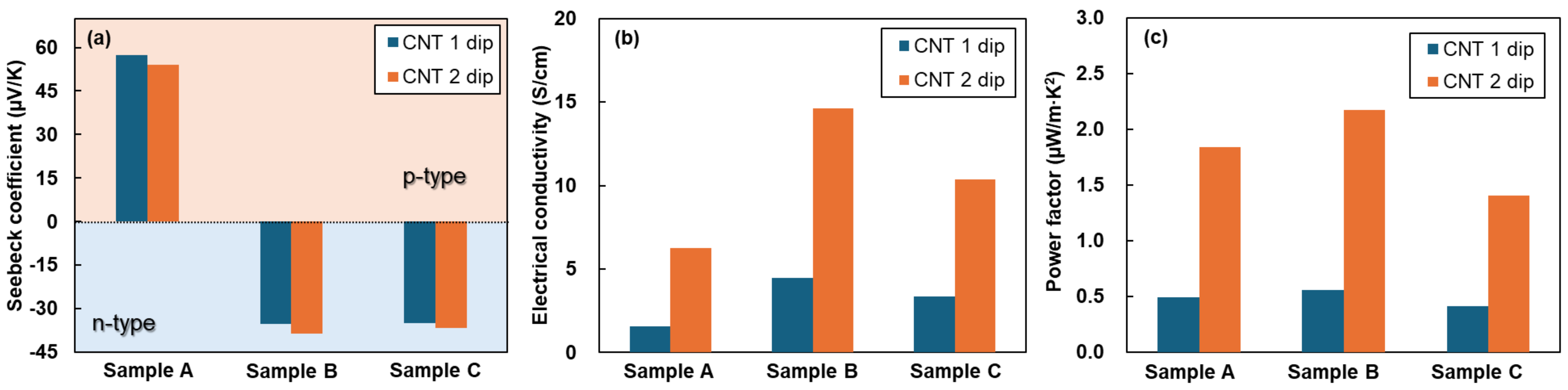
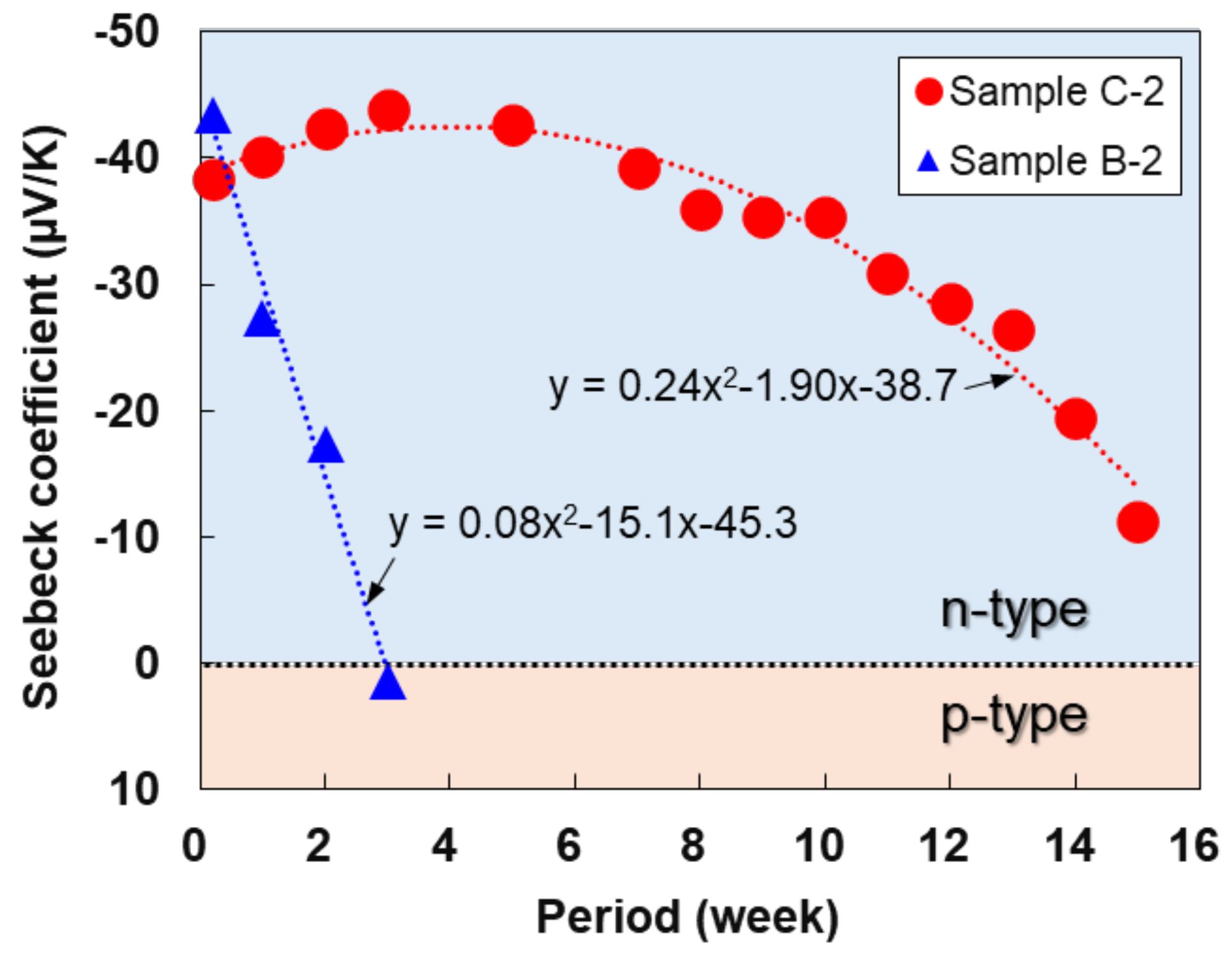
3.2. Thermoelectric Properties of SWCNT/Mesh Sheets

Figure 4 shows the in-plane thermoelectric properties of the SWCNT/mesh sheets at each stage of the manufacturing process. The measurements were performed immediately after each stage of the manufacturing process. In Figure 4a, Sample A, the pristine SWCNT/mesh sheet, exhibited positive Seebeck coefficients, and the Seebeck coefficient did not largely depend on the number of coatings. Sample B, comprising SWCNT/mesh sheets dipped in a DODMAC solution, exhibited negative Seebeck coefficients comparable to those of the samples with different dipping numbers. The mechanism behind the n-type stabilization is that electrons in DODMAC are transferred to the SWCNTs [52]. The average Seebeck coefficient of the two samples was −37 μV/K, which is lower than that of the n-type SWCNT films prepared by vacuum filtration using the same SWCNT powder and DODMAC in our previous report [52]. This is because the SWCNT/mesh sheets (Samples B-1 and B-2) contained not only the n-type dopant DODMAC but also the p-type dopant SDBS to form the SWCNT mesh structure. Conversely, n-type SWCNT films prepared by vacuum filtration used SWCNT ink containing DODMAC. Even when the fluoropolymer was sprayed on the SWCNT/mesh sheets in Samples C-1 and C-2, the Seebeck coefficient did not change significantly compared to Samples B-1 and B-2. In Figure 4b, it should be noted that the electrical conductivity was calculated using the total mesh thickness, including the PPS mesh thickness. The pristine SWCNT/mesh sheets of Sample A with a single SWCNT dip exhibited an electrical conductivity of 1.6 S/cm. After two dips, the conductivity increased by 6.3 S/cm due to the increase in SWCNTs on the PPS mesh. When the SWCNT/mesh sheets were dipped in a DODMAC solution, the electrical conductivity increased by a factor of 2–3 compared to the corresponding pristine samples (Sample A-1 and A-2), indicating an increase in carrier density due to n-type doping. However, when the fluoropolymer was sprayed on the SWCNT/mesh sheets for Sample C-1 and C-2, the electrical conductivity decreased compared to Sample B-1 and B-2 because the fluoropolymer layer disrupted electron transport. Nevertheless, the electrical conductivities of Sample C-1 and C-2 were higher than those of Sample A-1 and A-2. This is because the fluoropolymer layer is very thin, resulting in a relatively low insulating effect. In Figure 4c, the power factors of SWCNT/mesh sheets at each stage of the manufacturing process increased due to the double SWCNT dip, resulting in increased electrical conductivity. In particular, the highest power factor was exhibited in Sample B-2.
Figure 5 shows the maintenance period of the n-type Seebeck coefficient of the SWCNT/mesh sheets (Samples B-2 and C-2) in atmospheres with and without a fluoropolymer coating. The SWCNT/mesh sheets without the fluoropolymer coating exhibited a rapid decrease in the negative Seebeck coefficient and transitioned into a p-type Seebeck coefficient within approximately three weeks. Conversely, the SWCNT/mesh sheets with the fluoropolymer coating maintained a stable n-type Seebeck coefficient ranging from −35 to −45 μV/K for 10 weeks and a negative Seebeck coefficient for 15 weeks. The mechanism behind the difference in the n-type stabilization depends on the absence or presence of a fluoropolymer coating. When the fluoropolymer layer is absent from the surface, oxygen molecules are adsorbed on the surface and penetrate until they reach the SWCNT surface. Consequently, the electrons on the SWCNTs are transferred to oxygen molecules, which move the Fermi level closer to the valence bands, exhibiting a p-type Seebeck coefficient [56,57,58]. In contrast, when the fluoropolymer layer is present on the surface, oxygen molecules are adsorbed on the fluoropolymer layer; however, they have difficulty penetrating the fluoropolymer layer and reaching the SWCNT surface, maintaining the n-type Seebeck coefficient for a long time. Therefore, we demonstrated the long-term maintenance of n-type SWCNT/mesh sheets via cationic surfactant doping and subsequent fluoropolymer coating. However, the long-term maintenance in this study was not sufficient for its use as a power source for low-power electronic devices. Further trials, such as optimizing the DODMAC concentration and exploring n-type dopants and surface-coating materials, should be conducted to improve the long-term maintenance properties.

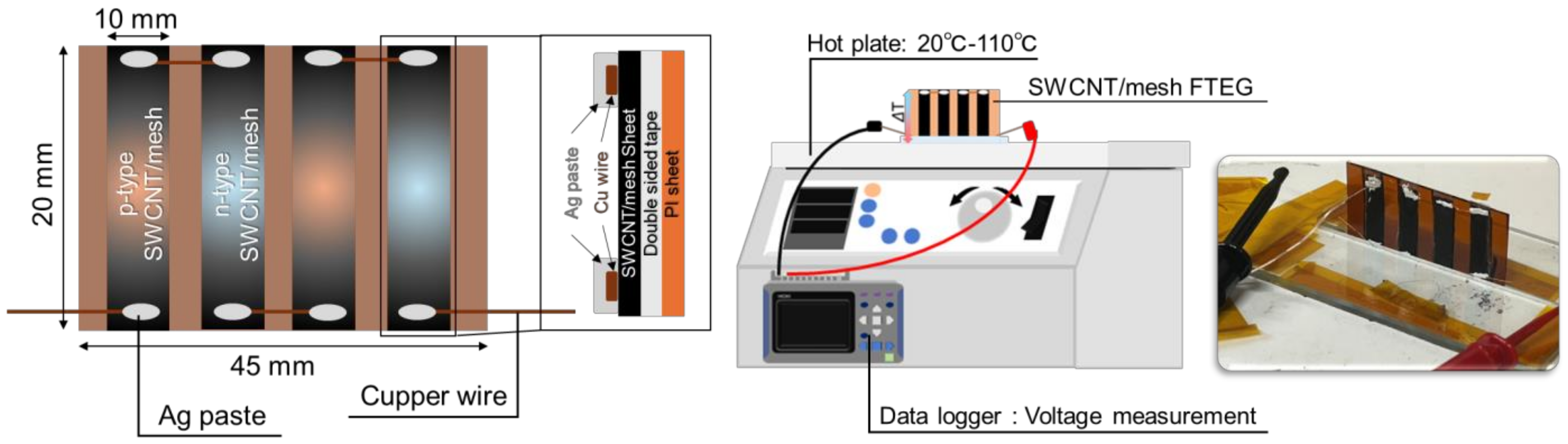
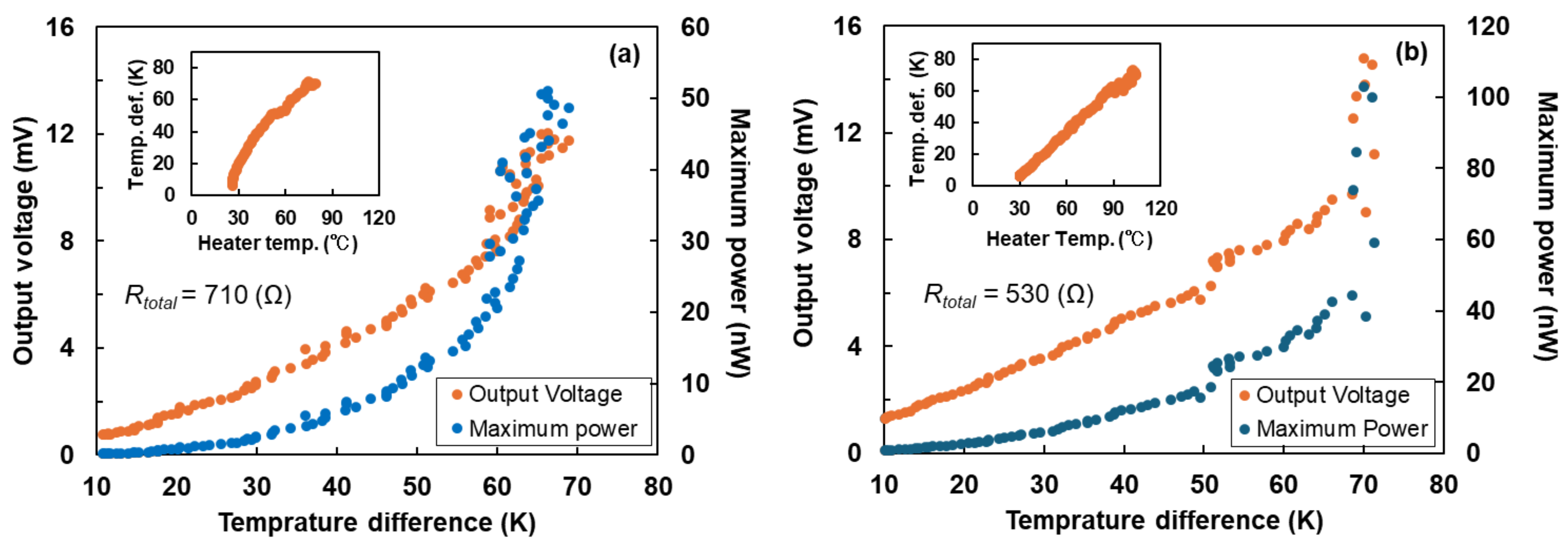
3.3. FTEGs with p- and n-Type SWCNT/Mesh Sheets

We fabricated FTEGs with p- and n-type SWCNT/mesh sheets and measured their performance, as shown in Figure 6. The structural novelty of the FTEGs is that the SWCNTs are deposited on the mesh surface without filling the mesh openings. This structure increases the surface area of the SWCNT film and allows for greater heat dissipation to the atmosphere, facilitated by the openings allowing wind to pass through. Consequently, the FTEGs can create greater temperature differences. To investigate the effect of the SWCNT layer thickness on the FTEGs, we prepared two FTEGs with different SWCNT layer thicknesses by changing the SWCNT dipping numbers. The first FTEG used p- and n-type SWCNT/mesh sheets prepared under the same conditions as samples A-1 and C-1, whereas the second FTEG used p- and n-type SWCNT/mesh sheets prepared under the same conditions as samples A-2 and C-2. To form the FTEG structure, all types of SWCNT/mesh sheets were cut to a length of 10 mm and width of 20 mm. Polyimide (PI) substrates with a thickness of 125 mm and double-sided PI tape were used to connect the PI substrates and SWCNT/mesh sheets. P-type and n-type sheets were alternately arranged in parallel at 5 mm intervals to form an FTEG consisting of four sheets. The sheets were connected in series using a copper wire. To measure the performance of power generation, the FTEG was placed vertically on a hot plate (DP-1L, As One, Osaka, Japan), and the end of the FTEG in contact with the hot plate was heated to a maximum of 108 °C. The temperatures at the top and bottom of the FTEG were measured by using two K-type thermocouples. Two Cu-wire electrodes were connected to the FTEG to measure the output voltage (Voc) with an accuracy of ±5%. Two thermocouples and two Cu wires were connected to a data logger (LR8432, HIOKI, Ueda, Japan). The maximum power Pmax was calculated from the Voc and the measured total electrical resistance of the FTEG Rtotal, as follows: Pmax = Voc2/4Rtotal.
Figure 7 shows the performance of FTEGs consisting of p- and n-type SWCNT/mesh sheets with different SWCNT dipping numbers. As shown in Figure 7a, the output voltage (Voc) and maximum power (Pmax) of the FTEGs with a single SWCNT dip increased with increasing temperature difference. When there was a temperature difference of 70 K with a heater temperature of 102 °C, as shown in the inset, Voc and Pmax were 12 mV and 50 nW, respectively. When the heater temperature increased, the measurement values fluctuated because the FTEG vibrated owing to increased heat convection. In Figure 7b, when the temperature difference of 71 K was generated in the FTEG, the heater temperature was 108 °C, as shown in the inset. This indicates that it is slightly more difficult for the FTEG with a double SWCNT dip to generate a temperature difference compared to the FTEG with a single SWCNT dip because the thermal conduction in the FTEG with a double dip is enhanced by the increase in the SWCNT layer thickness. For FTEGs with a double SWCNT dip, the Voc and Pmax increased with increasing temperature difference. The cause of the fluctuation in the measured values was the same as that shown in Figure 7a. When there was a temperature difference of 71 K with a heater temperature of 108 °C, as shown in the inset, the Voc and Pmax were 15 mV and 100 nW, respectively. Compared to the performance of the two FTEGs, the Voc was shown at similar values in the two FTEGs, but the Pmax of the FTEG with a double SWCNT dip was twice the value of a single SWCNT dip. This occurred because the resistance of the FTEG with a double SWCNT dip was lower than that of the FTEG with a single SWCNT dip. Since one of the characteristics of the FTEGs with SWCNT/mesh sheets is flexibility, the performance of the FTEG with double SWCNT dips under bending conditions was measured, and the results are presented in the Supplementary Information (Figure S4). When the radii of curvature of the SWCNT/mesh sheets were set at 50 and 15 mm, the performance of the FTEG did not exhibit a significant variation with the radius of curvature of the sheet.
In Table 2, the performances of FTEGs in this study are compared to those of FTEGs using p- and n-type SWCNT films prepared using the same starting material of SG-CNTs and the same cationic surfactant of DODMAC [52,59]. FTEGs using SWCNT/mesh sheets exhibited large temperature differences compared to those of FTEGs using SWCNT films on a polyimide substrate. This is because the SWCNT/mesh sheets have a high heat dissipation capacity. Since the number of pairs and temperature differences are different for each FTEG, we normalized this by dividing the Voc and Pmax by the number of pairs and temperature difference. The values of normalized Voc of FTEGs using SWCNT/mesh sheets in this study were comparable to those of two types of FTEGs using SWCNT films on a polyimide substrate. However, the values of normalized Pmax of FTEGs using SWCNT/mesh sheets in this study were lower than those of FTEGs using SWCNT films on a polyimide substrate. Therefore, to further enhance the performance of FTEGs using SWCNT/mesh sheets, the thermoelectric properties of the SWCNT layers should be improved by finding the best dopants using first-principles and molecular dynamics calculations [56,60]. In addition, the structure of the FTEGs should be optimized using computational fluid dynamics [2].

4. Conclusions

N-type SWCNT/mesh sheets with long-term stability were fabricated through cationic surfactant doping followed by fluoropolymer coating. Initially, we opted for p-type SWCNT inks with anionic surfactants over cationic ones due to the superior dispersion of p-type inks, enabling the formation of the SWCNT mesh structure.
In the first phase, PPS mesh sheets with a 100 μm aperture and 34 μm wire diameter were immersed in the p-type SWCNT ink to create an SWCNT layer on the mesh surface. To control the thickness of the SWCNT layer, we experimented with single and double dips. Subsequently, the SWCNT/mesh sheets were immersed in a solution containing only the cationic surfactant DODMAC, followed by heat treatment.
In the final stage, the fluoropolymer was sprayed on both surfaces of the SWCNT/mesh sheets. The resulting SWCNT/mesh sheets revealed unfilled openings in the mesh and a notably thin fluoropolymer layer on the SWCNT surface.
In terms of thermoelectric properties, the electrical conductivity of the sheets increased with the number of dips and slightly decreased with fluoropolymer applications due to its insulating effect. SWCNT/mesh sheets with fluoropolymer coatings retained the n-type Seebeck coefficient for 15 weeks, whereas those without it maintained it for approximately three weeks.
Moreover, FTEGs utilizing double-dipped p- and n-type SWCNT/mesh sheets exhibited a Voc of 15 mV and a Pmax of 100 nW at a temperature difference of 71 K. Thus, we have demonstrated the prolonged maintenance of n-type SWCNT/mesh sheets via cationic surfactant doping and subsequent fluoropolymer coating, along with power generation by FTEGs using these sheets. However, the long-term maintenance we have achieved is insufficient for powering low-power electronic devices, necessitating further performance enhancements.

Supplementary Materials

The following supporting information can be downloaded at: https://www.mdpi.com/article/10.3390/coatings14070794/s1, Figure S1: Surface morphology of SWCNT/mesh sheet prepared using SWCNT ink with DODMAC. (a) Optical photograph image, (b) lower magnification SEM image, and (c) higher magnification SEM image; Figure S2: Stress–strain curves of the PPS mesh, SWCNT/mesh sheets with different SWCNT dipping numbers; Figure S3: Molecular structures of DODMAC and SDBS; Figure S4: Performance of FTEG under bending conditions at the radius of curvature of the sheets evaluated at two radii: (a) 50 mm and (b) 15 mm.

Author Contributions

T.A. and M.T. conceived the study and designed the experiments. T.A. and M.T. wrote the manuscript. The experiments and data analyses were performed by T.A. All authors have read and agreed to the published version of the manuscript.

Funding

This research was funded by the Soken Project at Tokai University (grant number PJ2022-1) and the Hiratsuka City-Industry (Kanto Yakin Kogyo Co., Ltd. Hiratsuka, Japan) Academia Joint Research Commercialization Support Grant.

Institutional Review Board Statement

Not applicable.

Informed Consent Statement

Not applicable.

Data Availability Statement

Research data can be shared by M.T. if requested.

Acknowledgments

All authors thank H. Uchida and K. Nishiura at Zeon Corporation for providing the SG-CNT powders and M. Morikawa, Y. Oda, K. Miura, Y. Okano, and H. Yamamoto at Tokai University for their experimental support.

Conflicts of Interest

The authors declare that this study received funding from Hiratsuka City-Industry (Kanto Yakin Kogyo Co., Ltd. Hiratsuka, Japan). The funder was not involved in the study design, collection, analysis, interpretation of data, the writing of this article or the decision to submit it for publication.

References

  1. Fan, P.; Zheng, Z.-H.; Li, Y.-Z.; Lin, Q.-Y.; Luo, J.-T.; Liang, G.-X.; Cai, X.-M.; Zhang, D.-P.; Ye, F. Low-cost flexible thin film thermoelectric generator on zinc based thermoelectric materials. Appl. Phys. Lett. 2015, 106, 073901. [Google Scholar] [CrossRef]
  2. Kobayashi, A.; Konagaya, R.; Tanaka, S.; Takashiri, M. Optimized structure of tubular thermoelectric generators using n-type Bi2Te3 and p-type Sb2Te3 thin films on flexible substrate for energy harvesting. Sens. Actuators A 2020, 313, 112199. [Google Scholar] [CrossRef]
  3. Junlabhut, P.; Nuthongkum, A.; Sakulkalavek, A.; Harnwunggmoung, A.; Limsuwan, P.; Sakdanuphab, R. Enhancing the thermoelectric properties of sputtered Sb2Te3 thick films via post-annealing treatment. Surf. Coat. Technol. 2020, 387, 125510. [Google Scholar] [CrossRef]
  4. Norimasa, O.; Chiba, T.; Hase, M.; Komori, T.; Takashiri, M. Improvement of thermoelectric properties of flexible Bi2Te3 thin films in bent states during sputtering deposition and post-thermal annealing. J. Alloys Compd. 2022, 898, 162889. [Google Scholar] [CrossRef]
  5. Wang, Y.; Zhu, W.; Deng, Y.; Fu, B.; Zhu, P.; Yu, Y.; Li, J.; Guo, J. Self-powered wearable pressure sensing system for continuous healthcare monitoring enabled by flexible thin-film thermoelectric generator. Nano Energy 2020, 73, 104773. [Google Scholar] [CrossRef]
  6. Takei, K.; Honda, W.; Harada, S.; Arie, T.; Akita, S. Toward flexible and wearable human-interactive health-monitoring devices. Adv. Healthc. Mater. 2015, 4, 487–500. [Google Scholar] [CrossRef]
  7. Erdem, Ö.; Derin, E.; Shirejini, S.Z.; Sagdic, K.; Yilmaz, E.G.; Yildiz, S.; Akceoglu, G.A.; Inci, F. Carbon-based nanomaterials and sensing tools for wearable health monitoring devices. Adv. Mater. Technol. 2022, 7, 2100572. [Google Scholar] [CrossRef]
  8. Harman, T.C.; Paris, B.; Miller, S.E.; Goering, H.L. Preparation and some physical properties of Bi2Te3, Sb2Te3, and As2Te3. J. Phys. Chem. Solids 1957, 2, 181–190. [Google Scholar] [CrossRef]
  9. Satterthwaite, C.B.; Ure, R.W., Jr. Electrical and thermal properties of Bi2Te3. Phys. Rev. 1957, 108, 1164–1170. [Google Scholar] [CrossRef]
  10. Yim, W.M.; Rosi, F.D. Compound tellurides and their alloys for peltier cooling—A review. Solid-State Electron. 1972, 15, 1121–1134, IN1–IN2, 1135–1140. [Google Scholar] [CrossRef]
  11. Venkatasubramanian, R.; Siivola, E.; Colpitts, T.; O’Quinn, B. Thin-film thermoelectric devices with high room-temperature figures of merit. Nature 2001, 413, 597–602. [Google Scholar] [CrossRef] [PubMed]
  12. Poudel, B.; Hao, Q.; Ma, Y.; Lan, Y.; Minnich, A.; Yu, B.; Yan, X.; Wang, D.; Muto, A.; Vashaee, D.; et al. High-thermoelectric performance of nanostructured bismuth antimony telluride bulk alloys. Science 2008, 320, 634–638. [Google Scholar] [CrossRef] [PubMed]
  13. Hone, J.; Ellwood, I.; Muno, M.; Marvin, A.M.; Cohen, L.; Andrew, A.Z.; Rinzler, G.; Smalley, R.E. Thermoelectric power of single-walled carbon nanotubes. Phys. Rev. Lett. 1998, 80, 1042–1045. [Google Scholar] [CrossRef]
  14. Blackburn, J.L.; Ferguson, A.J.; Jaime, C.C.; Grunlan, C. Carbon-nanotube-based thermoelectric materials and devices. Adv. Mater. 2018, 30, 1704386. [Google Scholar] [CrossRef] [PubMed]
  15. Zhou, W.; Fan, Q.; Zhang, Q.; Cai, L.; Li, K.; Gu, X.; Yang, F.; Zhang, N.; Wang, Y.; Liu, H.; et al. High-performance and compact-designed flexible thermoelectric modules enabled by a reticulate carbon nanotube architecture. Nat. Commun. 2017, 8, 14886. [Google Scholar] [CrossRef] [PubMed]
  16. Avery, A.D.; Zhou, B.H.; Lee, J.; Lee, E.-S.; Miller, E.M.; Ihly, R.; Wesenberg, D.; Mistry, K.S.; Guillot, S.L.; Zink, B.L.; et al. Tailored semiconducting carbon nanotube networks with enhanced thermoelectric properties. Nat. Energy 2016, 1, 16033. [Google Scholar] [CrossRef]
  17. Bradley, K.; Jhi, S.-H.; Collins, P.G.; Hone, J.; Cohen, M.L.; Louie, S.G.; Zettl, A. Is the intrinsic thermoelectric power of carbon nanotubes positive? Phys. Rev. Lett. 2000, 85, 4361–4364. [Google Scholar] [CrossRef] [PubMed]
  18. Iijima, S.; Ichihashi, T. Single-shell carbon nanotubes of 1-nm diameter. Nature 1993, 363, 603–605. [Google Scholar] [CrossRef]
  19. Wilder, J.W.G.; Venema, L.C.; Rinzler, A.G.; Smalley, R.E.; Dekker, C. Electronic structure of atomically resolved carbon nanotubes. Nature 1998, 391, 59–62. [Google Scholar] [CrossRef]
  20. Dresselhaus, M.S.; Dresselhaus, G.; Saito, R.; Jorio, A. Raman spectroscopy of carbon nanotubes. Phy. Rep. 2005, 409, 47–99. [Google Scholar] [CrossRef]
  21. Sanchez-Valencia, J.R.; Dienel, T.; Gröning, O.; Shorubalko, I.; Mueller, A.; Jansen, M.; Amsharov, K.; Ruffieux, P.; Fasel, R. Controlled synthesis of single-chirality carbon nanotubes. Nature 2014, 512, 61–64. [Google Scholar] [CrossRef] [PubMed]
  22. Harutyunyan, A.R.; Chen, G.; Paronyan, T.M.; Pigos, E.M.; Kuznetsov, O.A.; Hewaparakrama, K.; Kim, S.M.; Zakharov, D.; Stach, E.A.; Sumanasekera, G.U. Preferential Growth of single-walled carbon nanotubes with metallic conductivity. Science 2009, 326, 116–120. [Google Scholar] [CrossRef] [PubMed]
  23. Ko, J.; Joo, Y. Review of sorted metallic single-walled carbon nanotubes. Adv. Mater. Interfaces 2021, 8, 2002106. [Google Scholar] [CrossRef]
  24. Javey, A.; Tu, R.; Farmer, D.B.; Guo, J.; Gordon, R.G.; Dai, H. High performance n-type carbon nanotube field-effect transistors with chemically doped contacts. Nano Lett. 2005, 5, 345–348. [Google Scholar] [CrossRef] [PubMed]
  25. Geier, M.L.; McMorrow, J.J.; Xu, W.; Zhu, J.; Kim, C.H.; Marks, T.J.; Hersam, M.C. Solution-processed carbon nanotube thin-film complementary static random access memory. Nat. Nanotechnol. 2015, 10, 944–948. [Google Scholar] [CrossRef] [PubMed]
  26. Scarselli, M.; Castrucci1, P.; Crescenzi1, M.D. Electronic and optoelectronic nano-devices based on carbon nanotubes. J. Phys. Condens. Matter. 2012, 24, 313202. [Google Scholar] [CrossRef] [PubMed]
  27. Lefebvre, J.; Ding, J.; Li, Z.; Finnie, P.; Lopinski, G.; Malenfant, P.R.L. High-purity semiconducting single-walled carbon nanotubes: A key enabling material in emerging electronics. Acc. Chem. Res. 2017, 50, 2479–2486. [Google Scholar] [CrossRef] [PubMed]
  28. MacLeod, B.A.; Stanton, N.J.; Gould, I.E.; Wesenberg, D.; Ihly, R.; Owczarczyk, Z.R.; Hurst, K.E.; Fewox, C.S.; Folmar, C.N.; Hughes, K.H.; et al. Large n-and p-type thermoelectric power factors from doped semiconducting single-walled carbon nanotube thin films. Energy Environ. Sci. 2017, 10, 2168–2179. [Google Scholar] [CrossRef]
  29. Kim, S.; Mo, J.H.; Jang, K.S. Solution-processed carbon nanotube buckypapers for foldable thermoelectric generators. ACS Appl. Mater. Interfaces 2019, 11, 35675–35682. [Google Scholar] [CrossRef]
  30. Berber, S.; Kwon, Y.-K.; Tománek, D. Unusually high thermal conductivity of carbon nanotubes. Phys. Rev. Lett. 2000, 84, 4613–4616. [Google Scholar] [CrossRef]
  31. Chiba, T.; Amma, Y.; Takashiri, M. Heat source free water floating carbon nanotube thermoelectric generators. Sci. Rep. 2021, 11, 14707. [Google Scholar]
  32. Nonoguchi, Y.; Nakano, M.; Murayama, T.; Hagino, H.; Hama, S.; Miyazaki, K.; Matsubara, R.; Nakamura, M.; Kawai, T. Simple salt-coordinated n-type nanocarbon materials stable in air. Adv. Funct. Mater. 2016, 26, 3021–3028. [Google Scholar] [CrossRef]
  33. Gonnet, P.; Liang, Z.; Choi, E.S.; Kadambala, R.S.; Zhang, C.; Brooks, J.S.; Wang, B.; Kramer, L. Thermal conductivity of magnetically aligned carbon nanotube buckypapers and nanocomposites. Curr. Appl Phys. 2006, 6, 119–122. [Google Scholar] [CrossRef]
  34. Kumanek, B.; Janas, D. Thermal conductivity of carbon nanotube networks: A review. J. Mater. Sci. 2019, 54, 7397–7427. [Google Scholar] [CrossRef]
  35. Hasan, M.N.; Wahid, H.; Nayan, N.; Ali, M.S.M. Inorganic thermoelectric materials: A review. Int. J. Energy Res. 2020, 44, 6170–6222. [Google Scholar] [CrossRef]
  36. Ghosh, T.; Dutta, M.; Sarkar, D.; Biswas, K. Insights into low thermal conductivity in inorganic materials for thermoelectrics. J. Am. Chem. Soc. 2022, 144, 10099–10118. [Google Scholar] [CrossRef]
  37. Xie, H.; Hao, S.; Bao, J.; Slade, T.J.; Snyder, G.J.; Wolverton, C.; Kanatzidis, M.G. All-inorganic halide perovskites as potential thermoelectric materials: Dynamic cation off-centering induces ultralow thermal conductivity. J. Am. Chem. Soc. 2020, 142, 9553–9563. [Google Scholar] [CrossRef] [PubMed]
  38. Gayner, C.; Kar, K.K. Recent advances in thermoelectric materials. Prog. Mater Sci. 2016, 83, 330–382. [Google Scholar] [CrossRef]
  39. Ren, P.; Liu, Y.; He, J.; Lv, T.; Gao, J.; Xu, G. Recent advances in inorganic material thermoelectrics. Inorg. Chem. Front. 2018, 5, 2380–2398. [Google Scholar] [CrossRef]
  40. Yao, Q.; Chen, L.; Zhang, W.; Liufu, S.; Chen, X. Enhanced thermoelectric performance of single-walled carbon nanotubes/polyaniline hybrid nanocomposites. ACS Nano 2010, 4, 2445–2451. [Google Scholar] [CrossRef]
  41. Kim, D.; Kim, Y.; Choi, K.; Grunlan, J.C.; Yu, C. Improved thermoelectric behavior of nanotube-filled polymer composites with poly(3,4-ethylenedioxythiophene) poly(styrenesulfonate). ACS Nano 2010, 4, 513–523. [Google Scholar] [CrossRef]
  42. Yu, C.; Choi, K.; Yin, L.; Grunlan, J.C. Light-weight flexible carbon nanotube based organic composites with large thermoelectric power factors. ACS Nano 2011, 5, 7885–7892. [Google Scholar] [CrossRef] [PubMed]
  43. Seki, Y.; Takahashi, M.; Takashiri, M. Effects of different electrolytes and film thicknesses on structural and thermoelectric properties of electropolymerized poly(3,4-ethylenedioxythiophene) films. RSC Adv. 2019, 9, 15957–15965. [Google Scholar] [CrossRef]
  44. Miura, K.; Amezawa, T.; Tanaka, S.; Takashiri, M. Improved heat dissipation of dip-coated SWCNT/mesh sheets with high flexibility and free-standing strength for thermoelectric generators. Coatings 2024, 14, 126. [Google Scholar] [CrossRef]
  45. Cheng, X.; Wang, X.; Chen, G. A convenient and highly tunable way to n-type carbon nanotube thermoelectric composite film using common alkylammonium cationic surfactant. J. Mater. Chem. A 2018, 6, 19030–19037. [Google Scholar] [CrossRef]
  46. Takenobu, T.; Takano, T.; Shiraishi, M.; Murakami, Y.; Ata, M.; Kataura, H.; Achiba, Y.; Iwasa, Y. Stable and controlled amphoteric doping by encapsulation of organic molecules inside carbon nanotubes. Nat. Mater. 2003, 2, 683–688. [Google Scholar] [CrossRef]
  47. Nonoguchi, Y.; Ohashi, K.; Kanazawa, R.; Ashiba, K.; Hata, K.; Nakagawa, T.; Adachi, C.; Tanase, T.; Kawai, T. Systematic conversion of single walled carbon nanotubes into n-type thermoelectric materials by molecular dopants. Sci. Rep. 2013, 3, 3344. [Google Scholar] [CrossRef] [PubMed]
  48. Horike, S.; Wei, Q.; Akaike, K.; Kirihara, K.; Mukaida, M.; Koshiba, Y.; Ishida, K. Bicyclic-ring base doping induces n-type conduction in carbon nanotubes with outstanding thermal stability in air. Nat. Commun. 2022, 13, 3517. [Google Scholar] [CrossRef]
  49. Oshima, K.; Yanagawa, Y.; Asano, H.; Shiraishi, Y.; Toshima, N. Improvement of stability of n-type super growth CNTs by hybridization with polymer for organic hybrid thermoelectrics. Synth. Met. 2017, 225, 81–85. [Google Scholar] [CrossRef]
  50. Tanaka, N.; Yamamoto, M.; Yamaguchi, I.; Hamasuna, A.; Honjo, E.; Fujigaya, T. Photolithographic p–n patterning of single-walled carbon nanotube sheets using photobase generators. J. Mater. Chem. A 2023, 11, 23278–23287. [Google Scholar] [CrossRef]
  51. Seki, Y.; Nagata, K.; Takashiri, M. Facile preparation of air-stable n-type thermoelectric single-wall carbon nanotube films with anionic surfactants. Sci. Rep. 2020, 10, 8104. [Google Scholar] [CrossRef] [PubMed]
  52. Amma, Y.; Miura, K.; Nagata, S.; Nishi, T.; Miyake, S.; Miyazaki, K.; Takashiri, M. Ultra-long air-stability of n-type carbon nanotube films with low thermal conductivity and all-carbon thermoelectric generators. Sci. Rep. 2022, 12, 21603. [Google Scholar] [CrossRef] [PubMed]
  53. Fernandes, R.M.F.; Abreu, B.; Claro, B.; Matat Buzaglo, M.; Regev, O.; Furó, I.; Marques, E.F. Dispersing carbon nanotubes with ionic surfactants under controlled conditions: Comparisons and insight. Langmuir 2015, 31, 10955–10965. [Google Scholar] [CrossRef] [PubMed]
  54. Amezawa, T.; Takashiri, M. Flexible p-n thermoelectric power generation device using SWCNT film with high heat dissipation effect. J. Adv. Sci. 2024, 36, 36110. (In Japanese) [Google Scholar] [CrossRef]
  55. Hata, K.; Futaba, D.N.; Mizuno, K.; Namai, T.; Yumura, M.; Iijima, S. Water-assisted highly efficient synthesis of impurity-free single-walled carbon nanotubes. Science 2004, 306, 1362–1364. [Google Scholar] [CrossRef] [PubMed]
  56. Yonezawa, S.; Chiba, T.; Seki, Y.; Takashiri, M. Origin of n type properties in single wall carbon nanotube films with anionic surfactants investigated by experimental and theoretical analyses. Sci. Rep. 2021, 11, 5758. [Google Scholar] [CrossRef] [PubMed]
  57. Zhou, C.; Kong, J.; Yenilmez, E.; Dai, H. Modulated chemical doping of individual carbon nanotubes. Science 2000, 290, 1552–1555. [Google Scholar] [CrossRef] [PubMed]
  58. Collins, P.G.; Bradley, K.; Ishigami, M.; Zettl, A. Extreme oxygen sensitivity of electronic properties of carbon nanotubes. Science 2000, 287, 1801–1804. [Google Scholar] [CrossRef] [PubMed]
  59. Konagaya, R.; Takashiri, M. Dual-type flexible-film thermoelectric generators using all-carbon nanotube films. Coatings 2023, 13, 209. [Google Scholar] [CrossRef]
  60. Yonezawa, S.; Amma, Y.; Miura, K.; T Chiba, T.; Takashiri, M. Air stability of n-type single-walled carbon nanotube films with anionic surfactants investigated using molecular dynamics. Colloids Surf. A 2021, 625, 126925. [Google Scholar] [CrossRef]
Figure 1. Manufacturing process of SWCNT/mesh sheets.
Coatings 14 00794 g001
Figure 2. SEM images of SWCNT/mesh sheets at each stage of the manufacturing process: (a) PPS mesh sheet, (b) Sample A-1, (c) Sample A-2, (d) Sample B-1, (e) Sample B-2, (f) Sample C-1, and (g) Sample C-2.
Coatings 14 00794 g002
Figure 3. XPS spectra of SWCNT/mesh sheets with fluoropolymer spraying: (a) entire XPS spectra, (b) C1s spectra, (c) F1s spectra, and (d) O1s spectra.
Coatings 14 00794 g003
Figure 4. In-plane thermoelectric properties of SWCNT/mesh sheets measured at 25 °C: (a) Seebeck coefficient, (b) electrical conductivity and (c) power factor.
Coatings 14 00794 g004
Figure 5. Changes in Seebeck coefficients of SWCNT/mesh sheets over time with and without fluoropolymer coating.
Coatings 14 00794 g005
Figure 6. Manufacturing process and measurement procedure of the FTEG with p- and n-type SWCNT/mesh sheets.
Coatings 14 00794 g006
Figure 7. Power generation performance of FTEGs with p- and n-type SWCNT/mesh sheets: (a) single SWCNT dip and (b) double SWCNT dip.
Coatings 14 00794 g007
Table 1. Sample name and thickness of SWCNT/mesh sheets at each stage of the manufacturing process.
SampleSWCNT
Dipping
DODMAC
Coating
Fluoropolymer
Splaying
Thickness
(µm)
Sample A-1SingleUntreatedUntreated64
Sample A-2DoubleUntreatedUntreated71
Sample B-1SingleTreatedUntreated61
Sample B-2DoubleTreatedUntreated73
Sample C-1SingleTreatedTreated63
Sample C-2DoubleTreatedTreated70
Table 2. Comparison of performance of SWCNT-FTEGs.
SWCNT-FTEGsNumber of PairsT
[K]
Voc
[mV]
Pmax
[nW]
Normalized Voc
[mV/(pair∙K)]
Normalized Pmax
[nW/(pair∙K)]
Reference
SWCNT/mesh (Single dip)27012500.090.36This work
SWCNT/mesh (Double dip)271151000.110.70This work
SWCNT films on Polyimide
(Single face)
460244000.101.67Ref. [52]
SWCNT films on Polyimide
(Double faces)
1525408900.112.37Ref. [59]
Disclaimer/Publisher’s Note: The statements, opinions and data contained in all publications are solely those of the individual author(s) and contributor(s) and not of MDPI and/or the editor(s). MDPI and/or the editor(s) disclaim responsibility for any injury to people or property resulting from any ideas, methods, instructions or products referred to in the content.

