Article

Catalytic Activity Evaluation of Molten Salt-Treated Stainless Steel Electrodes for Hydrogen Evolution Reaction in Alkaline Medium

1
Graduate School of Engineering Science, Akita University, Akita 010-8502, Japan
2
Faculty of Non-Ferrous Metals, AGH University of Science and Technology, 30-059 Kraków, Poland
*
Authors to whom correspondence should be addressed.
Coatings 2024, 14(7), 796; https://doi.org/10.3390/coatings14070796
Submission received: 30 May 2024 / Revised: 17 June 2024 / Accepted: 24 June 2024 / Published: 26 June 2024
(This article belongs to the Special Issue Coatings as Key Materials in Catalytic Applications)

Abstract

:
The goal of this research is to fabricate a novel type of highly active porous electrode material, based on stainless steel and dedicated to water electrolyzers. The main novelty of the presented work is the innovative application of the molten salts treatment, which allows the design of a highly developed porous structure, which characterizes significantly higher catalytic activity than untreated steel substrates. The equimolar mixture of NaCl and KCl with 3.5 mol% AlF3 was used as the molten salt. The surface modification procedure includes the deposition of an Al layer with application at the potential of −1.8 V and following dissolution at −0.9 V, to create a porous alloy surface. The cathodic polarization measurements of the prepared porous stainless steel electrodes were measured in a 10 mass% KOH solution. Moreover, the amount of hydrogen generated during constant voltage electrolysis with a hydrogen sensor in situ was also measured. The porous stainless steel alloy showed higher current density at lower potentials in the cathodic polarization compared to untreated stainless steel. The cathodic polarization measurements in alkaline solution showed that the porous 304 stainless steel alloy is an excellent cathode material.

1. Introduction

The use of fossil fuels generates greenhouse gases, contributing to global warming, a major problem. Consequently, efforts are underway to mitigate greenhouse gas emissions. Hydrogen energy, which does not emit greenhouse gases, is gaining attention [1,2]. Alkaline water electrolysis, using renewable energy, is a method for producing this hydrogen, termed green hydrogen. However, production costs are high, necessitating cost-effective methods for alkaline water electrolysis. Therefore, there is a need to produce hydrogen efficiently and at a low cost.
Cathode electrodes have been developed to achieve high-efficiency hydrogen generation [3,4,5,6,7,8,9,10,11,12,13,14,15,16,17,18,19,20]. Historically, Ni alloys were predominantly used due to their corrosion resistance in alkaline water [8,9,10,11,12,13,14,15,16,17,18,19]. However, stainless steel has replaced Ni alloys [21,22,23,24,25]. The reason for this is that Ni is an expensive material, is provided a stable supply, and is difficult to process, so there is a need to develop inexpensive materials for electrodes used in alkaline water electrolysis. Therefore, stainless steel, which exhibits high corrosion resistance even in aqueous alkaline solutions, is being used. P.A. Selembo et al. are developing a low-cost cathode electrode made of stainless steel. The results show that stainless steel has higher hydrogen generation performance than Pt [21]. Y. Zhang et al. also investigated the hydrogen generation amount of stainless steel cathode electrodes and showed that stainless steel mesh gave good results [22]. Therefore, to enhance the properties of this stainless steel alloy, it is necessary to make it porous.
The authors have successfully generated porous surface layers of various alloys using an ionic liquid, molten salt [26,27]. In this study, Al was electrodeposited, as in previous studies by the authors, and aluminide was formed on the stainless steel surface. Therefore, we will investigate the hydrogen generation behavior of the porous stainless steel surface layer in an alkaline aqueous solution by dissolving Al after Al electrodeposition. However, in situ measurement of hydrogen generated by alkaline water electrolysis is challenging. The authors previously conducted in situ measurements of hydrogen generated by steam oxidation of metals using a proton conductor—a solid electrolyte—and the results showed accurate determination of trace amounts of hydrogen generated during the tests [28]. Moreover, this type of electrode can be successfully applied as a highly active material for oxidation of organic compounds [29]. In this study, we fabricated porous stainless steel using Al electrodeposition and Al dissolution in molten salt, aiming to evaluate its cathode performance. The surface and cross section of the fabricated samples were observed using SEM. To assess cathode performance, we measured the cathode polarization curve in 10 mass% KOH and the amount of hydrogen generated in situ using a hydrogen sensor fabricated with a solid electrolyte. We also elucidated the relationship between the amount of hydrogen generated and the porous stainless steel.

2. Experimental Section

SUS304 and SUS316 (The Nilaco Corporation, Tokyo, Japan) were utilized as base material samples. Table 1 displays the composition of each alloy. The sample surface was polished with emery paper up to #800 grit and subsequently cleaned using ultrasonic cleaning in acetone. The surface area of the sample is approximately 2 cm2.
Figure 1 shows the formation procedure of porous stainless steel. After the deposition of aluminum (Al), a porous layer is created by selectively dissolving only Al. Aluminum electrodeposition cannot be conducted in an aqueous solution, therefore a molten salt was selected as the medium. For the electrolytic bath, an equimolar NaCl-KCl mixed salt containing 3.5 mol% AlF3 was used. Following Al electrodeposition, only Al was dissolved in the same molten salt to generate a porous surface.
The electrolysis cell employed in this experiment is detailed in a previous report [24]. The reference electrode was a mullite tube with an outer diameter of 6 mm and a length of 500 mm, housing NaCl-KCl-AgCl (45:45:10 mol%) mixed salt with an immersed Ag wire. The melt temperature during Al electrodeposition and Al dissolution was maintained at 750 °C. Throughout the experiment, argon (Ar) gas was introduced into the cell at a flow rate of 200 cc min−1.
Al deposition was executed at −1.8 V for 60 min using constant potential electrolysis. Subsequently, Al dissolution occurred at −0.9 V in all samples. The dissolution time continued until the current density reached zero. Post-treatment, the sample was removed from the bath, and salts that adhered to the sample surface were removed by washing with water.
The cross section of the treated sample underwent observation and analysis using a scanning electron microscope (SEM, Tokyo, Japan) and an X-ray micro-analyzer (Electron Probe Micro-Analyzer: EPMA, Tokyo, Japan). Furthermore, the deposits were identified using X-ray diffraction, with CuKα rays employed as the X-ray source.
To evaluate the hydrogen generation behavior of the sample after treatment, the cathodic polarization measurements were performed in a 10 mass% KOH solution. The potential sweep rate was 100 mV min−1, and the temperature of the solution was maintained at 30 °C. The potential was swept in the cathode direction from the open circuit potential, which stabilized after immersion in solution, and measurements were taken until the potential reached −1.25 V.
Furthermore, the amount of hydrogen generated during electrolysis was measured in situ using a gas sensor. The measuring device and principle are detailed in a previous report [28]. Electrolysis was performed by applying the voltage equal 4.0 V in a 10 mass% KOH aqueous solution. Then, the amount of hydrogen generated at the cathode was measured by a carrier gas (Ar gas) and a gas sensor.
The amount of hydrogen generated was then calculated from the measured hydrogen partial pressure. If it is assumed that the measurement gas is an ideal gas and that Charles’s law holds true, then Equation (1) holds true.
PH2(dVr/dt) = (dn/dt)RTr
where PH2 is the measured hydrogen pressure, Vr is the gas flow rate measured at the temperature Tr, n is the amount of gas generated, and Tr is the temperature at which the flow rate was measured. In this study, the temperature was 25 °C. The amount of hydrogen generated per unit time was calculated, and the total amount of hydrogen generated was calculated at each temperature.

3. Results and Discussion

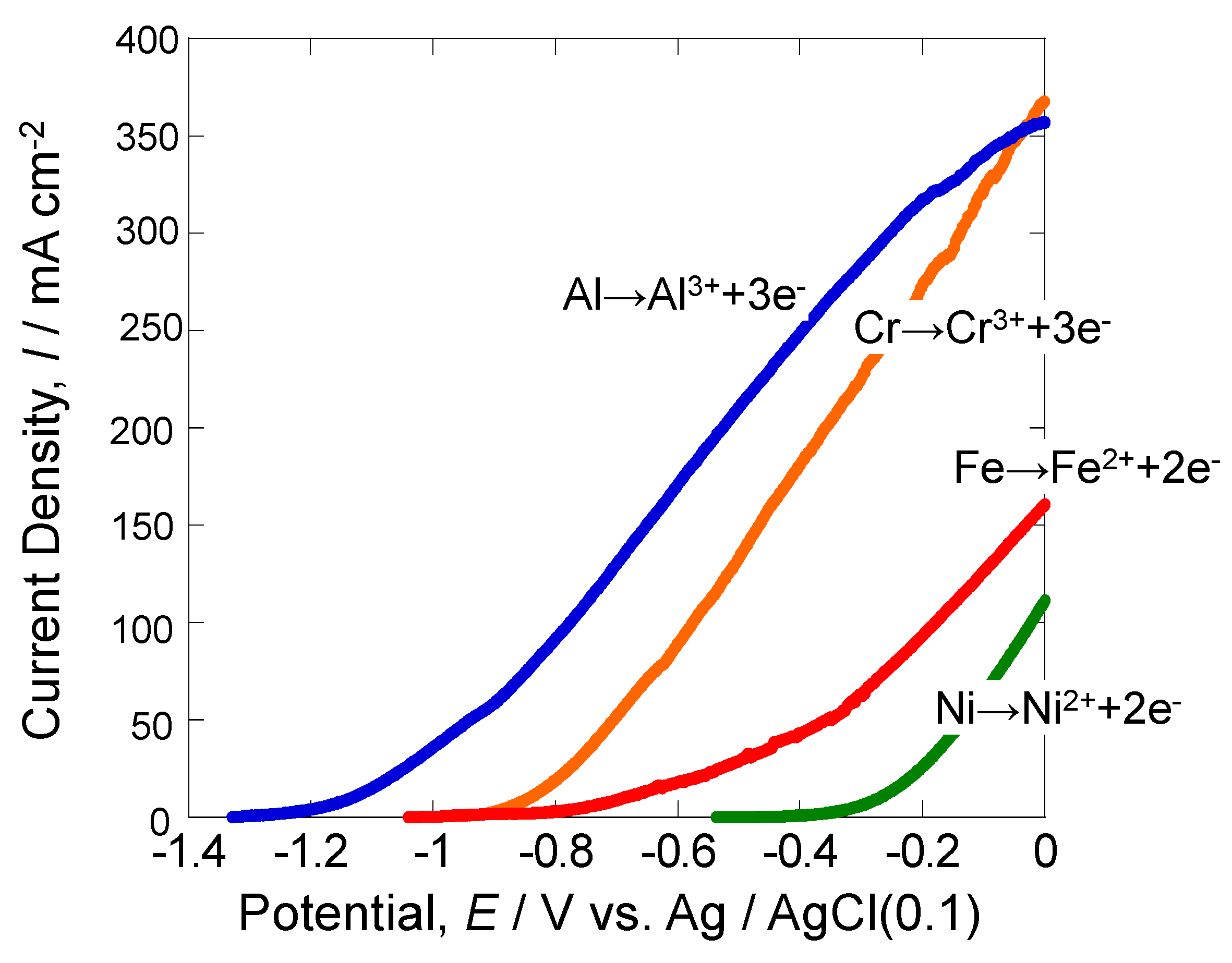
3.1. Anodic Polarization Curves of Various Metals

Figure 2 illustrates the anodic polarization curves of various metals, measured in NaCl-KCl-3.5 mol% AlF3 molten salt at 750 °C. Concerning aluminum (Al), experiments were conducted using samples where Al was electrodeposited on stainless steel. The obtained data reveal that Al dissolves at the lowest potential, while Ni dissolves at the highest potential. To induce the dissolution reaction of Al selectively, constant polarization at −0.9 V seems to be effective. In the case of chromium (Cr), an increase in anodic current, indicating the dissolution process, was observed from around −0.85 V. Additionally, for iron (Fe), an increase in anodic current was noted from around −0.75 V. These findings underscore that Al exhibits the highest solubility, whereas Ni exhibits the highest resistance for electrochemical dissolution in molten salts mixture.

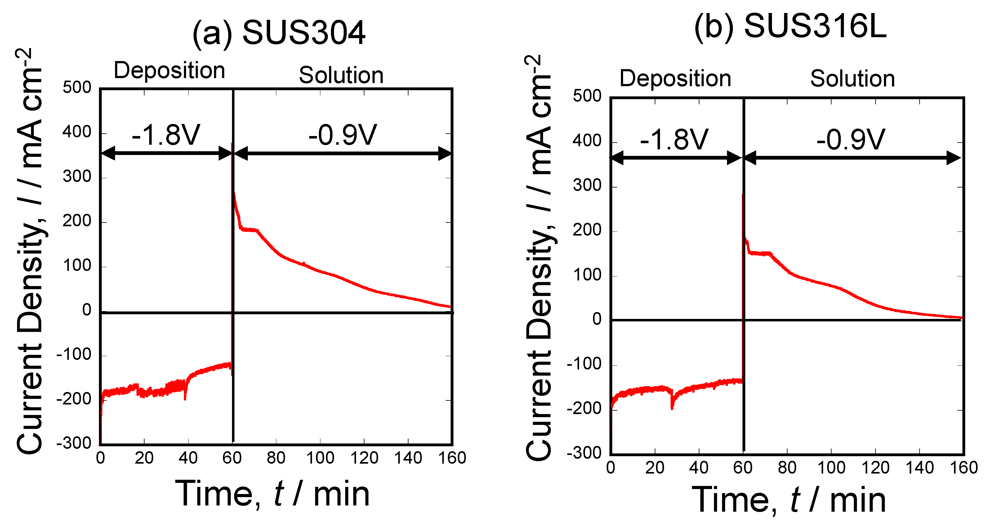
3.2. Current Density–Time Curve during Al Deposition and Al Dissolution onto SUS304 and SUS316L Stainless Steel Substrates

Figure 3 shows the current density–time curves during both Al electrodeposition and Al dissolution. Al was deposited at −1.8 V for 1 h in NaCl-KCl-3.5 mol% AlF3 molten salt at 750 °C. Subsequently, only Al was dissolved at −0.9 V. The figures illustrate that a cathodic current flows during electrodeposition, while an anodic current flows during dissolution. Notably, the experiment was sustained until the dissolution current reached zero, indicating the complete dissolution of all Al. During electrodeposition, an initially high cathode current is evident, followed by a stabilization around −120 mA cm−2 at 60 min for SUS304 and around −150 mA cm−2 at 60 min for 316L. The dissolution current exhibited an initial peak, followed by a rapid decline. Subsequently, the dissolution reaction of Al occurred at a consistent rate until the current value reached zero.

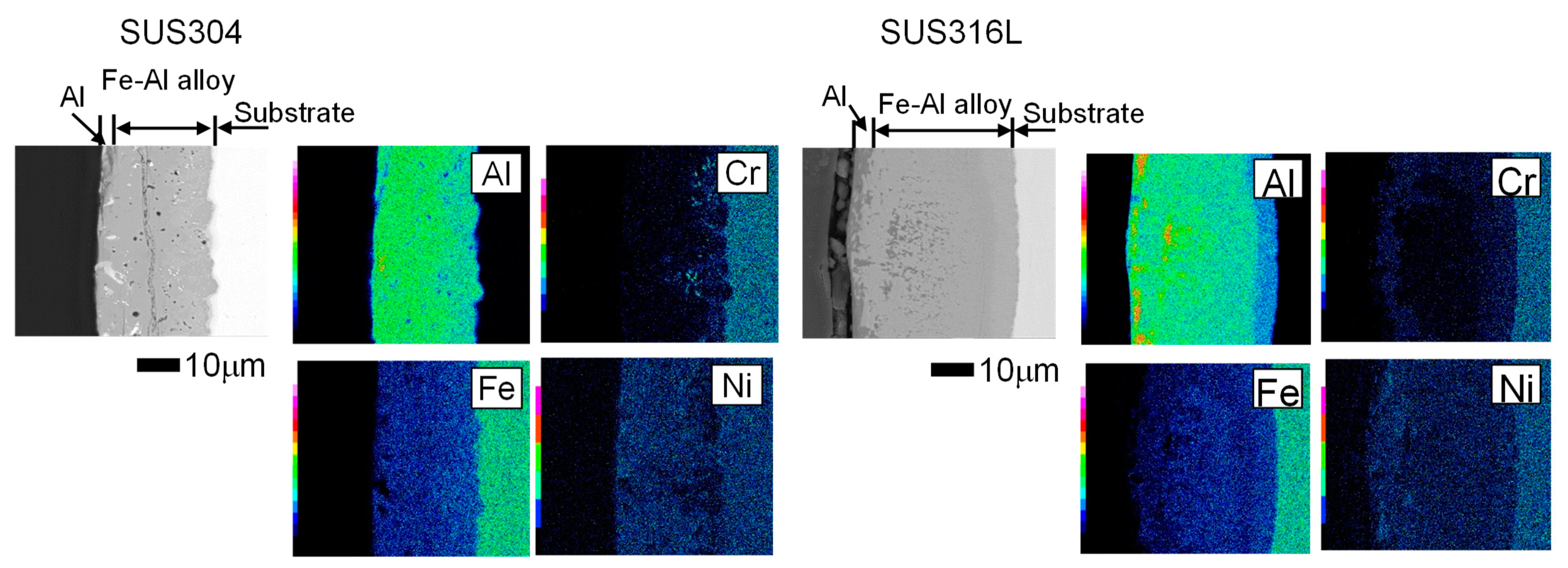
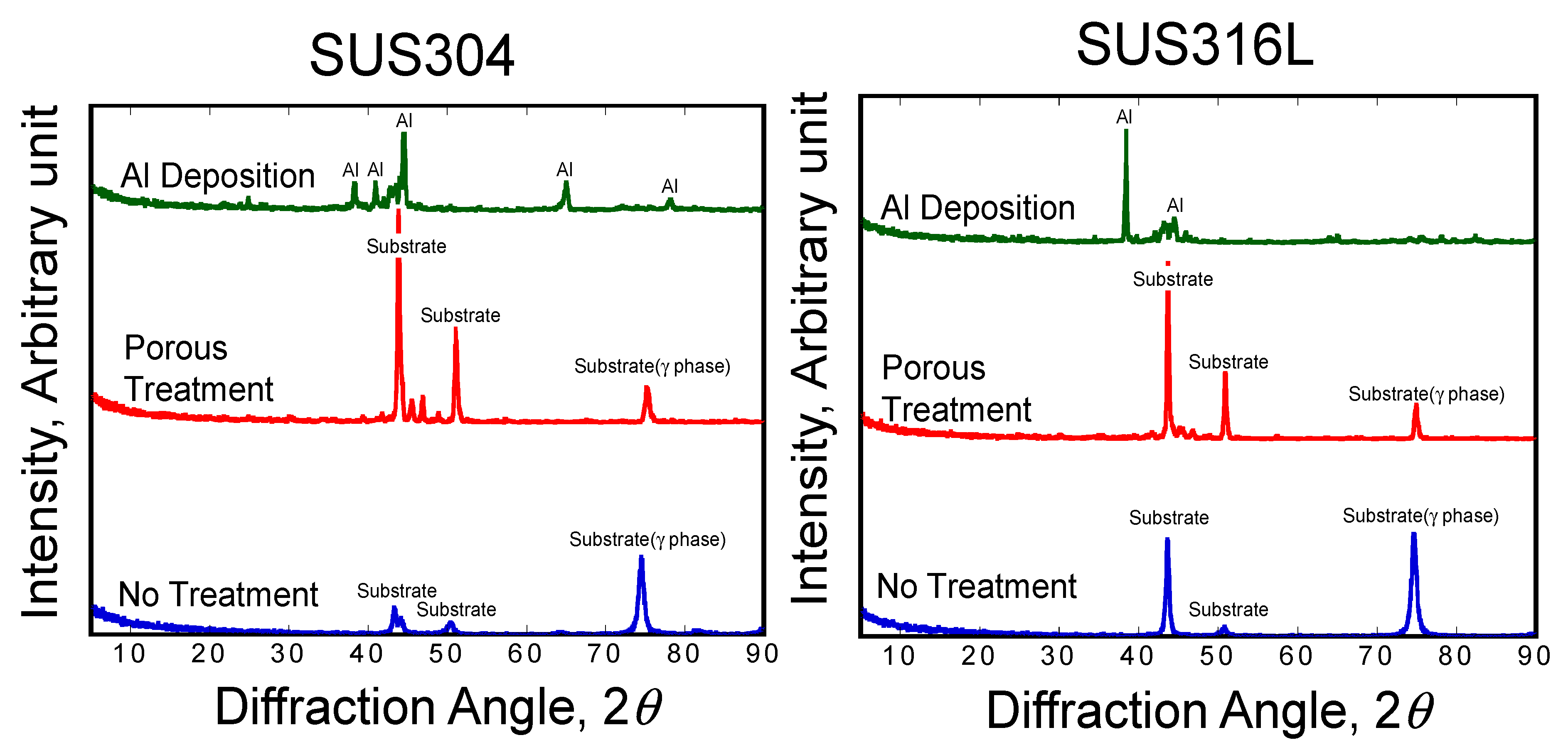
3.3. Morphology of Stainless Steel Samples after Al Molten Salts Electrodeposition

Figure 4 displays scanning electron microscope (SEM) images revealing the surface characteristics of the samples subsequent to the electrodeposition of aluminum (Al) at 750 °C and −1.8 V in NaCl-KCl-3.5 mol% AlF3 molten salt. Two types of stainless steel, SUS304 and SUS316L, were employed in this process, and the outcomes are detailed below.
Following the Al electrodeposition, the samples were cleaned via ultrasonic cleaning in water to eliminate any molten salt residues adhering to the surface. The samples were dried and then used for observation. Numerous irregularities were observed on the surfaces of both SUS304 and SUS316L samples. Importantly, no defects such as voids or empty spaces were detected. Moreover, it is evident that the surface has acquired a solidified structure due to the electrodeposition of liquid Al. This observation confirms that no voids or empty spaces were present on the sample surface after the Al electrodeposition process.
Figure 5 presents scanning electron microscope (SEM) images captured using backscattered electron mode, shows the cross-sectional views of two stainless steel samples after the deposition of aluminum (Al) at −1.8 V in NaCl-KCl-3.5 mol% AlF3 molten salt at 750 °C. In both samples, an Al-rich Fe aluminide layer was observed on the surface. This occurrence is related to the electrodeposited Al being in a liquid state and diffusing into the substrate. Furthermore, a substantial deposited layer was formed in the 316L sample. This layer had an approximate thickness of 60 μm, exhibited good adhesion to the stainless steel, and presented a uniform deposition across the sample surface. The cross-sectional views provide valuable insights into the structural changes induced by the Al deposition process in the stainless steel samples.

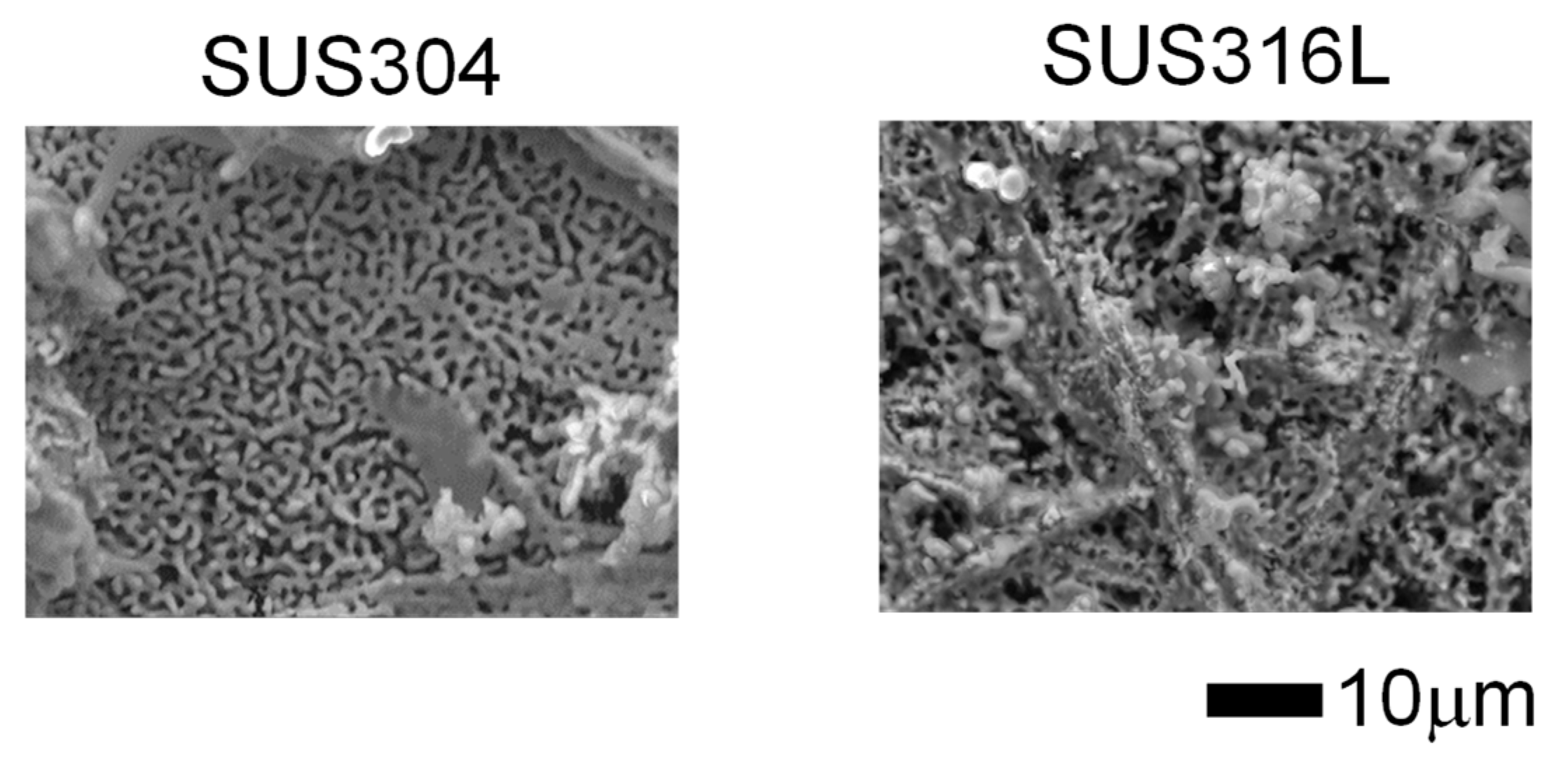
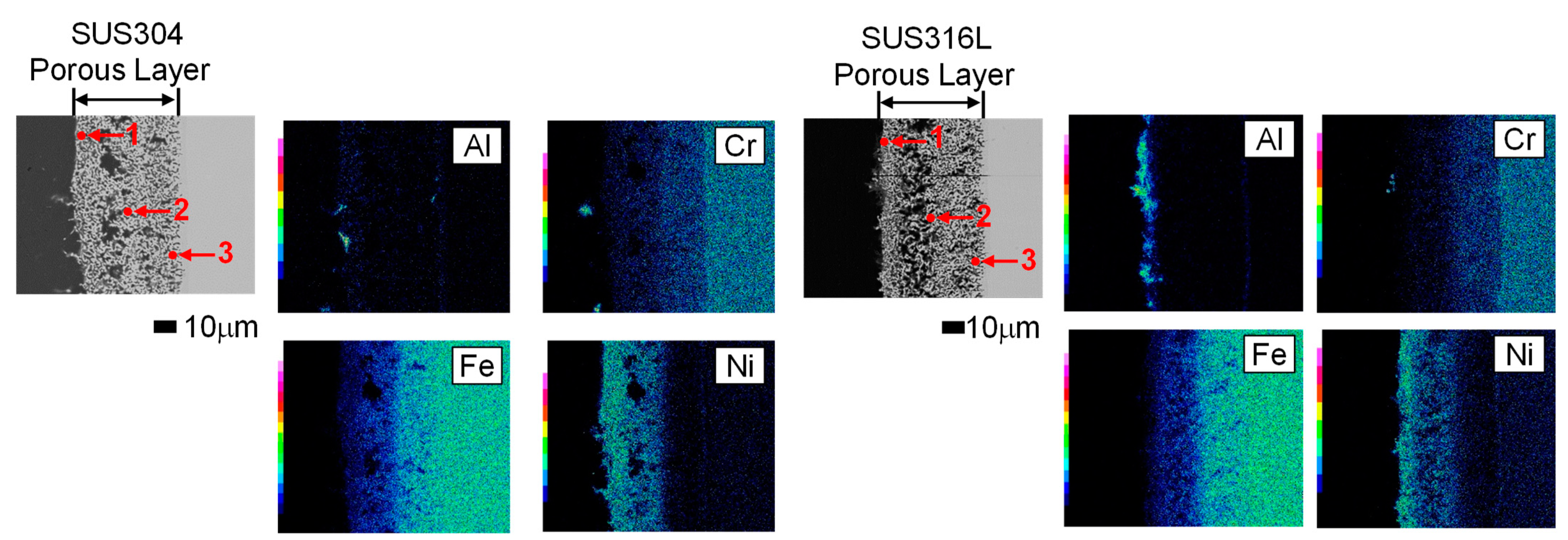
3.4. Morphology and Composition of Porous Steel Samples after Molten Salts Treatment and Dissolution of Al

Figure 6 illustrates the surface morphology of two different steel samples subjected to molten salts treatment by the electrodeposition and dissolution of aluminum. The Al deposition conditions were set at −1.8 V for 60 min, and the Al dissolution conditions were maintained at −0.9 V for both samples. On the surface, many voids were observed with irregular shape. Finer voids were registered for SUS304, while in 316L, the voids exhibited a more complex structure. The porous morphology is strongly dependent on the type of stainless steel used for molten salt treatment.
In Figure 7, the cross-sectional structure of the two porous samples after treatment by the electrodeposition and dissolution of Al is presented. A fine porous layer is evident in both samples, with a thickness of approximately 50 mm in each case. Analysis revealed no presence of Al in the porous layer, indicating complete dissolution and removal of the electrodeposited Al. The obtained microstructure of the steel-based samples seems to be more suitable and compact than in other types of molten salt-modified materials obtained in our previous studies: Co-Ni, Ni, and Ni-Pt. This outcome can be related with the presence of different microstructural carbides and intermetallics, typical for steel, which are highly resistant to phase formation with molten Al and the further dealloying process.
Table 2 displays point analysis results of the cross section shown in Figure 7. In SUS304 steel, at point 1, Cr concentration was 6.81 at.%, Fe was 21.9 at.%, and Ni was 71.29 at.%, indicating a concentration of Ni on the surface. Moreover, point 2 on the substrate side, Cr concentration was 13.2 at.%, Fe was 55.4 at.%, and Ni was 26.4 at.%, with the Ni concentration decreasing rapidly. This observation suggests an increase in Ni concentration on the surface of SUS304 with porous treatment. In case of SUS316L, the point 1, Cr was 1.78 at.%, Fe was 11.09 at.%, and Ni was 87.14 at.%, revealing a higher Ni concentration than in SUS304. At point 2 on the substrate side, Cr was 10.86 at.%, Fe was 53.51 at.%, and Ni was 35.63 at.%, with a rapid decrease in Ni concentration. The surface Ni concentration varied depending on the type of stainless steel, potentially influencing the behavior of hydrogen generation.
Figure 8 presents the XRD diffraction patterns obtained for samples after Al electrodeposition and dissolution of the porous-treated sample. The formation of the Fe-Al phase occurred during Al deposition at −1.8 V and 750 °C for 60 min in both samples. The subsequent dissolution of Al and the porous treatment resulted in a profile similar to that of the substrate material, indicating that the formation of the porosity in the material is not changing the original crystalline structure even after treatment in molten salt at 750 °C.

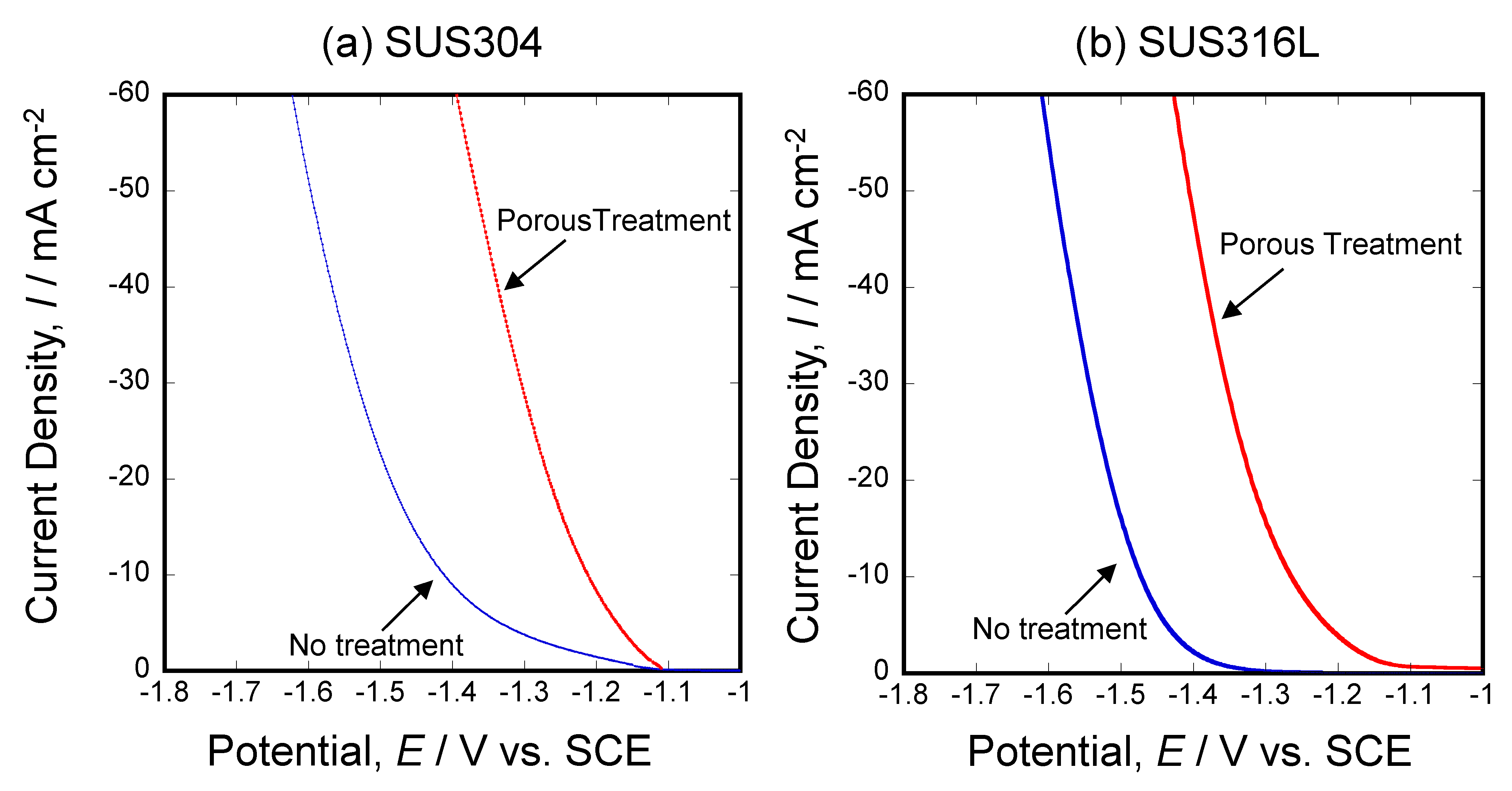
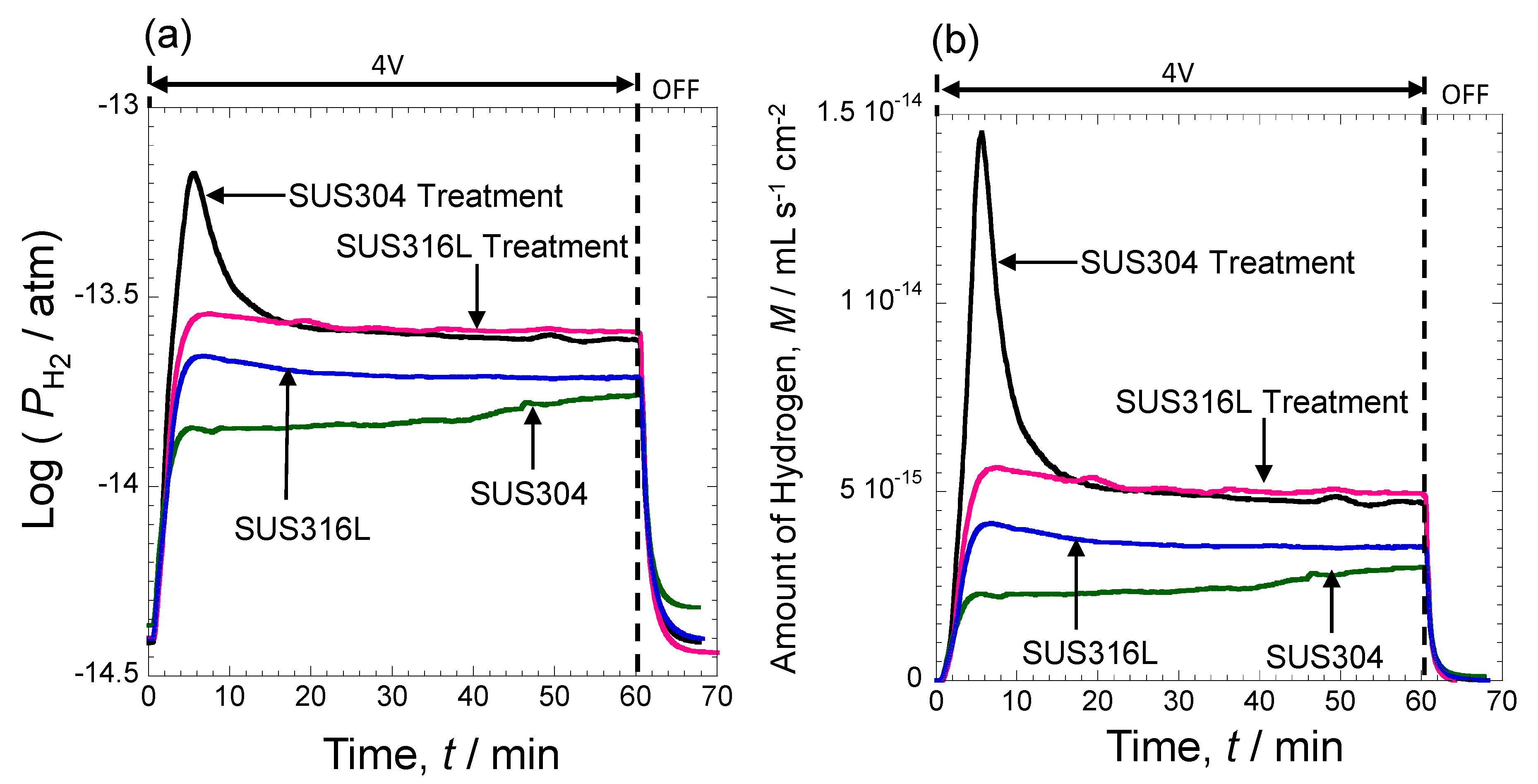
3.5. Electrochemical Activity Evaluation of Porous Stainless Steel Electrodes Obtained by Molten Salts Treatment in Hydrogen Evolution Reaction

Figure 9 presents the results of cathodic polarization scans measured in a 10 mass% KOH solution for both samples: untreated substrate and stainless steel after molten salts treatment. It should be noted that the cathodic current density registered in polarization scans differs significantly between the porous samples and the non-treated substrate. In untreated SUS304, an increase in cathodic current was observed when the voltage was below −1.4 V. Conversely, with porous treatment, a rise in cathodic current was noted from −1.1 V. Similarly, in untreated SUS316L, an increase in cathode current occurred from around −1.35 V, while porous treatment led to an increase from around −1.1 V. Both porous-treated samples reach a cathode current of 60 mA cm−2 at −1.4 V for SUS304 and −1.44 V for SUS316L, indicating that porous SUS304 achieves this current at −1.4 V. This highlights a substantial change in the catalytic activity for hydrogen evolution, which can be observed under more positive potential values than in the case of non-treated steel substrates.
Figure 10 presents the hydrogen partial pressure (Figure 10a) measured with a hydrogen sensor and the hydrogen partial pressure calculated using the ideal gas equation for hydrogen generated at the cathode electrode during electrolysis at 4.0 V in 10 mass% KOH, showing the amount of hydrogen generated (Figure 10b). Equation (1) was used to calculate the amount of hydrogen generated from the hydrogen partial pressure, as shown in the experimental method section. In Figure 10a, the untreated sample exhibited a low hydrogen partial pressure, but this pressure increased significantly with porous treatment. Particularly, a rapid rise in hydrogen partial pressure was observed initially in SUS304 steel, indicating that porous treatment enhances the amount of hydrogen generated during electrolysis. It was also evident that hydrogen was rapidly generated in the initial stage of treated SUS304 steel. However, the temporal change in the amount of hydrogen generated, calculated from the hydrogen partial pressure, revealed that the amount of hydrogen generated was lower for both samples than in the untreated sample. Nevertheless, it is evident that the amount of hydrogen generated increases significantly through treatment. By integrating Figure 10b, the total amount of hydrogen generated can be calculated. As a result, it was revealed that the untreated SUS304, which showed the lowest value, had a value of 1.8 × 10⁻¹¹ mL, but with treatment, it reached 4.0 × 10⁻¹¹ mL, more than double the initial amount. Comparing the overvoltage (10 mA cm−2) in past papers, the sample created in this research has an overvoltage of 80 mV, which is considered a good result [30]. These findings highlight the successful fabrication of a porous stainless steel surface and the consequential improvements in cathode performance and hydrogen generation efficiency. The observed characteristics indicate the potential applications of porous stainless steel in efficient hydrogen production processes.

4. Conclusions

Two types of stainless steel were employed as substrates where aluminum was deposited from a molten salt electrolyte to create a layer of Fe-Al alloy. Subsequently, the deposited Al was liquefied under high-temperature conditions, resulting in the penetration into the stainless steel substrate. The solid-state reaction between Al and Fe led to formation of a mixture of intermetallic phases. Obtained Al-rich phases were electrochemically dissolved with the application of −0.9 V potential, revealing a porous stainless steel alloy layer.
Furthermore, the cathodic performance of the prepared porous stainless steel alloy surface layer was tested and compared with untreated stainless steel substrates. Additionally, the amount of hydrogen generated during constant voltage electrolysis in a 10 mass% KOH solution was quantified using a hydrogen gas sensor. The obtained results of the conducted study can be summarized as follows:
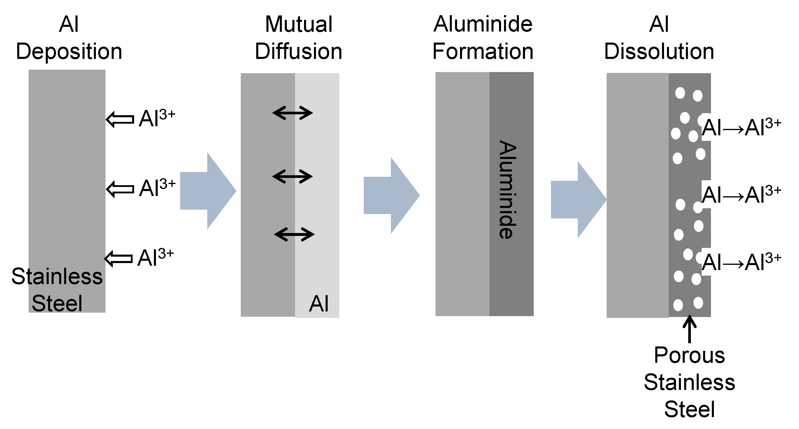
  • A porous stainless steel surface was successfully fabricated through Al electrodeposition and Al dissolution experiments.
  • It was observed that porous treatment allows to obtain a compact surface with numerous voids.
  • The porous stainless steel alloy exhibited a higher current density at lower potentials in the cathodic polarization curve compared to the untreated sample
  • In a hydrogen generation experiment using constant voltage electrolysis, the steel samples after porous treatment produced more hydrogen, especially SUS304 which generated the highest amount of hydrogen and produced 4 × 10⁻¹¹ mL of hydrogen on a surface area of 2 cm2 in 1 h of electrolysis time.

Author Contributions

Conceptualization, M.F., H.T., D.K., M.W. and P.Ż.; methodology, M.F.; formal analysis, M.F., H.T. and D.K.; investigation, M.F., H.T., D.K. and M.W.; data curation, M.F., H.T. and D.K.; writing—original draft preparation, M.F.; writing—review and editing, H.T., D.K., M.W. and P.Ż.; supervision, M.F.; project administration, M.F., H.T., D.K., M.W. and P.Ż. All authors have read and agreed to the published version of the manuscript.

Funding

This research received no external funding.

Institutional Review Board Statement

Not applicable.

Informed Consent Statement

Not applicable.

Data Availability Statement

The original contributions presented in the study are included in the article, further inquiries can be directed to the corresponding authors.

Conflicts of Interest

The authors declare no conflict of interest.

References

  1. Momirlan, M.; Veziroglu, T.N. The properties of hydrogen as fuel tomorrow in sustainable energy system for a cleaner planet. Int. J. Hydrogen Energy 2005, 30, 795–802. [Google Scholar] [CrossRef]
  2. Safizadeh, F.; Ghali, E.; Houlachi, G. Electrocatalysis developments for hydrogen evolutuion reaction in alkaline solutions—A Review. Int. J. Hydrogen Energy 2015, 40, 256–274. [Google Scholar] [CrossRef]
  3. Chen, L.; Lasia, A. Study of the kinetics of hydrogen evolution reaction on nickel-zinc alloy electrodes. J. Electrochem. Soc. 1991, 138, 3321–3328. [Google Scholar] [CrossRef]
  4. Chen, L.; Lasia, A. Study of the kinetics of hydrogen evolution reaction on nickel-zinc powder electrodes. J. Electrochem. Soc. 1992, 139, 3214–3219. [Google Scholar] [CrossRef]
  5. Rami, A.; Lasia, A. Kinetics of hydrogen evolution on Ni-Al alloy electrodes. J. Appl. Electrochem. 1992, 22, 376–382. [Google Scholar] [CrossRef]
  6. Birry, L.; Lasia, A. Studies of the hydrogen evolution reaction on Raney nickel-molybdenum electrodes. J. Appl. Electrochem. 2004, 34, 735–749. [Google Scholar] [CrossRef]
  7. Navarro-Flores, E.; Chong, Z.; Omanovic, S. Characterization of Ni, NiMo, NiW and NiFe electroactive coatings as electrocatalysts for hydrogen evolution in an acidic medium. J. Mol. Catal. A Chem. 2005, 226, 179–197. [Google Scholar] [CrossRef]
  8. Mauer, A.E.; Kirk, D.W.; Thorpe, S.J. The role of iron in the prevention of nickel electrode deactivation in alkaline electrolysis. Electrochim. Acta 2007, 52, 3505–3509. [Google Scholar] [CrossRef]
  9. Dong, H.; Lei, T.; He, Y.; Xu, N.; Huang, B.; Liu, C.T. Electrochemical performance of porous Ni3Al electrodes for hydrogen evolution reaction. Int. J. Hydrogen Energy 2011, 36, 12112–12120. [Google Scholar] [CrossRef]
  10. Mullis, A.M.; Bigg, T.D.; Adkins, N.J. A microstructural investigation of gas atomized Raney type Al-27.5 at.% Ni catalyst precursor alloys. J. Alloys Compd. 2015, 648, 139–148. [Google Scholar] [CrossRef]
  11. Yu, L.; Lei, T.; Nao, B.; Jiang, Y.; He, Y.; Liu, C.T. Characteristics of a sintered porous Ni-Cu alloy cathode for hydrogen production in a potassium hydroxide solution. Energy 2016, 97, 498–505. [Google Scholar] [CrossRef]
  12. Brown, I.J.; Sotiropoulos, S. Preparation and characterization of microporous Ni coatings as hydrogen evolving cathodes. J. Appl. Electrochem. 2000, 30, 107–111. [Google Scholar] [CrossRef]
  13. Tanaka, S.; Hirose, N.; Tanaki, T.; Ogata, Y.H. The effect of tin ingredients on electrocatalytic activity of Raney-Ni prepared by mechanical alloying. Int. J. Hydrogen Energy 2001, 26, 47–53. [Google Scholar] [CrossRef]
  14. Yüce, A.O.; Döner, A.; Kardaş, G. NiMn composite electrodes as cathode material for hydrogen evolution reaction in alkaline solution. Int. J. Hydrogen Energy 2013, 38, 4466–4473. [Google Scholar] [CrossRef]
  15. Chade, D.; Berlouis, L.; Infield, D.; Cruden, A.; Nielsen, P.N.; Mathiesen, T. Evaluation of Raney nickel electrodes prepared by atmos pheric plasma spraying for alkaline water electrolysers. Int. J. Hydrogen Energy 2013, 38, 14380–14390. [Google Scholar] [CrossRef]
  16. Lupi, C.; Dell’Era, A.; Pasquali, M. Nickel-cobalt electrodeposited alloys for hydrogen evolution in alkaline media. Int. J. Hydrogen Energy 2009, 34, 2101–2106. [Google Scholar] [CrossRef]
  17. González-Buch, C.; Herraiz-Cardona, I.; Ortega, E.; García-Antón, J.; Pérez-Herranz, V. Synthesis and characterization of macroporous Ni, Co and Ni-Co electrocatalytic deposits for hydrogen evolution reaction in alkaline media. Int. J. Hydrogen Energy 2013, 38, 10157–10169. [Google Scholar] [CrossRef]
  18. Wang, C.; Zhang, Q.; Liu, Z.; Li BZhao, W.; Zhang, C.; Jiang, S.; Wang, J.; Liu, K.; He, S. CoO supported NiFe layered double hydroxide sandwich-like nanosheets on hierarchical carbon framework for efficient electrocatalytic oxygen evolution. ChemSusChem 2024, 17, e202301703. [Google Scholar] [CrossRef] [PubMed]
  19. Zhou, Z.; Springer, M.A.; Geng, W.; Zhu, X.; Li, T.; Li, M.; Jing, Y.; Heine, T. Rational Design of Two-Dimensional Binary Polymers from Heterotriangulenes for Photocatalytic Water Splitting. J. Phys. Chem. Lett. 2021, 33, 8134–8140. [Google Scholar] [CrossRef]
  20. Dong, B.; Yu, N.; Wang, Q.Y.; Ren, J.K.; Zhang, X.Y.; Zhang, Z.J.; Fan, R.Y.; Liu, D.P.; Chai, Y.M. Double active sites promoting hydrogen evolution activity and stability of CoRuOH/Co2P by rapid hydrolysis. Chin. Chem. Lett. 2024, 35, 109221. [Google Scholar] [CrossRef]
  21. Lavorante, M.J.; Franco, J.I. Performance of stainless steel 316L electrode with modified surface to be use in alkaline water electrolyers. Int. J. Hydrogen Energy 2016, 41, 9731–9737. [Google Scholar] [CrossRef]
  22. David, M.; Ocampo-Martínez, C.; Sánchez-Pena, R. Advance in alkaline water electrolyzers: A review. J. Energy Storage 2019, 23, 392–403. [Google Scholar] [CrossRef]
  23. Moureaux, F.; Stevens, P.; Toussaint, G. Timely-activated 316L stainless steel: A low cost, durable and active electrode for oxygen evolution reaction in concentrated alkaline environments. Appl. Catal. B Environ. 2019, 258, 117963. [Google Scholar] [CrossRef]
  24. Zamanizadeh, H.R.; Sunde, S.; Pollet, B.G.; Seland, F. Tailoring the oxide surface composition of stainless steel for improved OER performance in alkaline water electrolysis. Electrochim. Acta 2022, 424, 140561. [Google Scholar] [CrossRef]
  25. Zamanizadeh, H.R.; Barnett, A.O.; Sunde, S.; Pollet, B.G.; Seland, F. Performance of activated stainless steel and nickel-based anodes in alkaline water electrolyser. J. Power Sources 2023, 564, 232828. [Google Scholar] [CrossRef]
  26. Fukumoto, M.; Sugiuchi, K.; Nakajima, K. Formation of porous Ni surface by electrodeposition and dissolution in molten salt. Int. J. Hydrogen Energy 2020, 45, 28252–28259. [Google Scholar] [CrossRef]
  27. Nakajima, K.; Fukumoto, M. Porous Ni-Co surface formation and analysis of hydrogen generation by gas sensor. Int. J. Hydrogen Energy 2021, 46, 26263–26271. [Google Scholar] [CrossRef]
  28. Fukumoto, M.; Nakajima, K.; Kawamori, Y. Investigation of Alumina Formation and Oxidation Rate of Ni-5wt%Al-Xwt%Cr Alloy Using Hydrogen Sensor and Oxygen Pump Sensor. Oxid. Met. 2020, 94, 191–204. [Google Scholar] [CrossRef]
  29. Fukumoto, M.; Takahashi, H.; Kutyla, D.; Wojnicki, M.; Zabinski, P. Morphological investigation and electrochemical performance evaluation of novel porous Ni-Pt produced by Al-deposition/dissolution in molten salts for hydrogen and oxygen evolution reaction. Int. J. Hydrogen Energy 2024, 49, 754–765. [Google Scholar] [CrossRef]
  30. Huang, L.; Hou, Y.; Yu, Z.; Peng, Z.; Wang, L.; Huang, J.; Zhang, B.; Qian, L.; Wu, L.; Li, Z. Pt/Fe-NF electrode with high double-layer capacitance for efficient hydrogen evolution reaction in alkaline media. Int. J. Hydrogen Energy 2017, 42, 9458–9466. [Google Scholar] [CrossRef]
Figure 1. Schematic diagram of the formation procedure of porous stainless steel.
Coatings 14 00796 g001
Figure 2. Anodic polarization curves of various metals in the 50 mol%NaCl-50 mol%KCl molten salt at 750 °C.
Coatings 14 00796 g002
Figure 3. Time dependence of current by the constant potential polarization at 750 °C in the 48.25 mol%NaCl-48.25 mol%KCl-3.5 mol%AlF3 molten salt. (a) SUS304; (b) SUS316L.
Coatings 14 00796 g003
Figure 4. Morphology of sample surface after Al electrodeposition with constant potential polarization at −1.8 V at 750 °C for 1 h.
Coatings 14 00796 g004
Figure 5. Cross section of microstructure after Al electrodeposition with constant potential polarization at −1.8 V at 750 °C for 1 h.
Coatings 14 00796 g005
Figure 6. Morphology of sample surface after Al electrodeposition and dissolution with constant potential polarization at −1.8 V to −0.9 V at 750 °C.
Coatings 14 00796 g006
Figure 7. Cross-sectional microstructure of sample after Al electrodeposition and dissolution with constant potential polarization at −1.8 V to −0.9 V at 750 °C. 1 Top Part, 2 Middle Part, 3 Under Part.
Coatings 14 00796 g007
Figure 8. X-ray diffraction patterns registered for substrate, Al-deposited, and porous samples obtained for SUS304 (left) and SUS316L (right) stainless steel.
Coatings 14 00796 g008
Figure 9. Cathodic polarization scans registered for different types of steel substrates and porous samples in 10 mass% KOH solution. (a) SUS304; (b) SUS316L.
Coatings 14 00796 g009
Figure 10. Time dependence of hydrogen partial pressure (a) and amount of hydrogen generated (b) during electrolysis at 4 V.
Coatings 14 00796 g010
Table 1. Chemical composition of SUS304 and SUS316L (mass%).
CrNiMnSiMoFe
SUS30417%–19%8%–11%<2%<1% Balance
SUS316L16%–18%10%–14%<2%<1%2%–3%Balance
Table 2. Point analysis results at each point in Figure 7.
SUS304 (at.%)SUS316L (at.%)
CrFeNi CrFeNi
16.8121.9071.2911.7811.0987.14
213.255.426.4210.8653.5135.63
313.9158.3827.70314.9672.3112.73
Disclaimer/Publisher’s Note: The statements, opinions and data contained in all publications are solely those of the individual author(s) and contributor(s) and not of MDPI and/or the editor(s). MDPI and/or the editor(s) disclaim responsibility for any injury to people or property resulting from any ideas, methods, instructions or products referred to in the content.

