
Contrast Role of Third Body Layer and Hard Abrasives in the Wear Process of a TiAlSiN Hardness-Modulated Multilayer Coating: A Case Study on the Effect of Normal Load and Velocity

Abstract
:1. Introduction
2. Experimental Details
3. Results
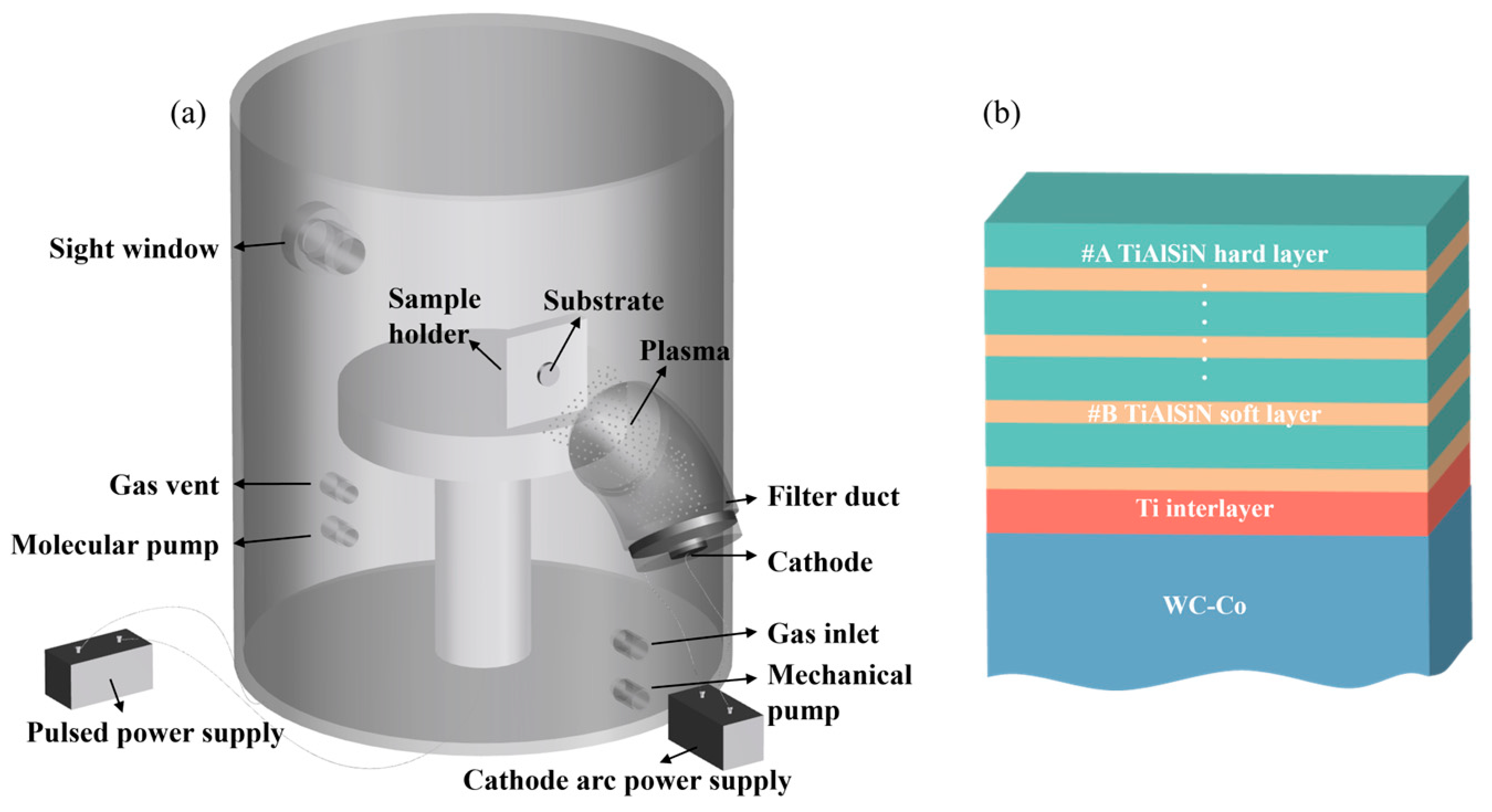
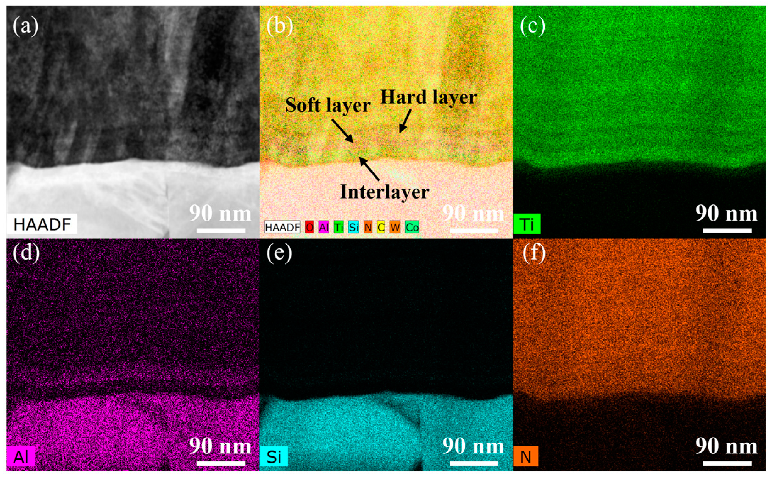
3.1. Morphology and Composition of TiAlSiN Multilayer Coating
3.2. Mechanical Properties of TiAlSiN Multilayer Coating
3.3. Tribological Properties of TiAlSiN Multilayer Coating
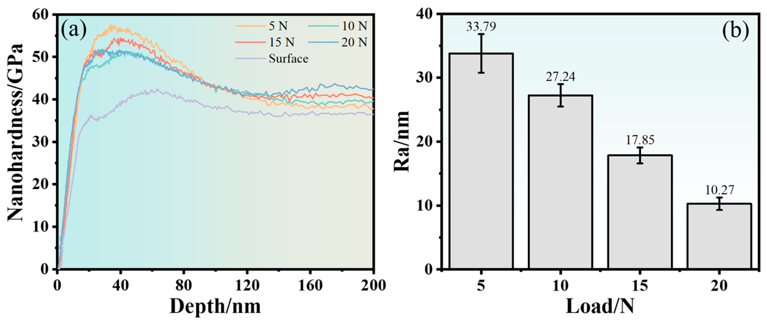
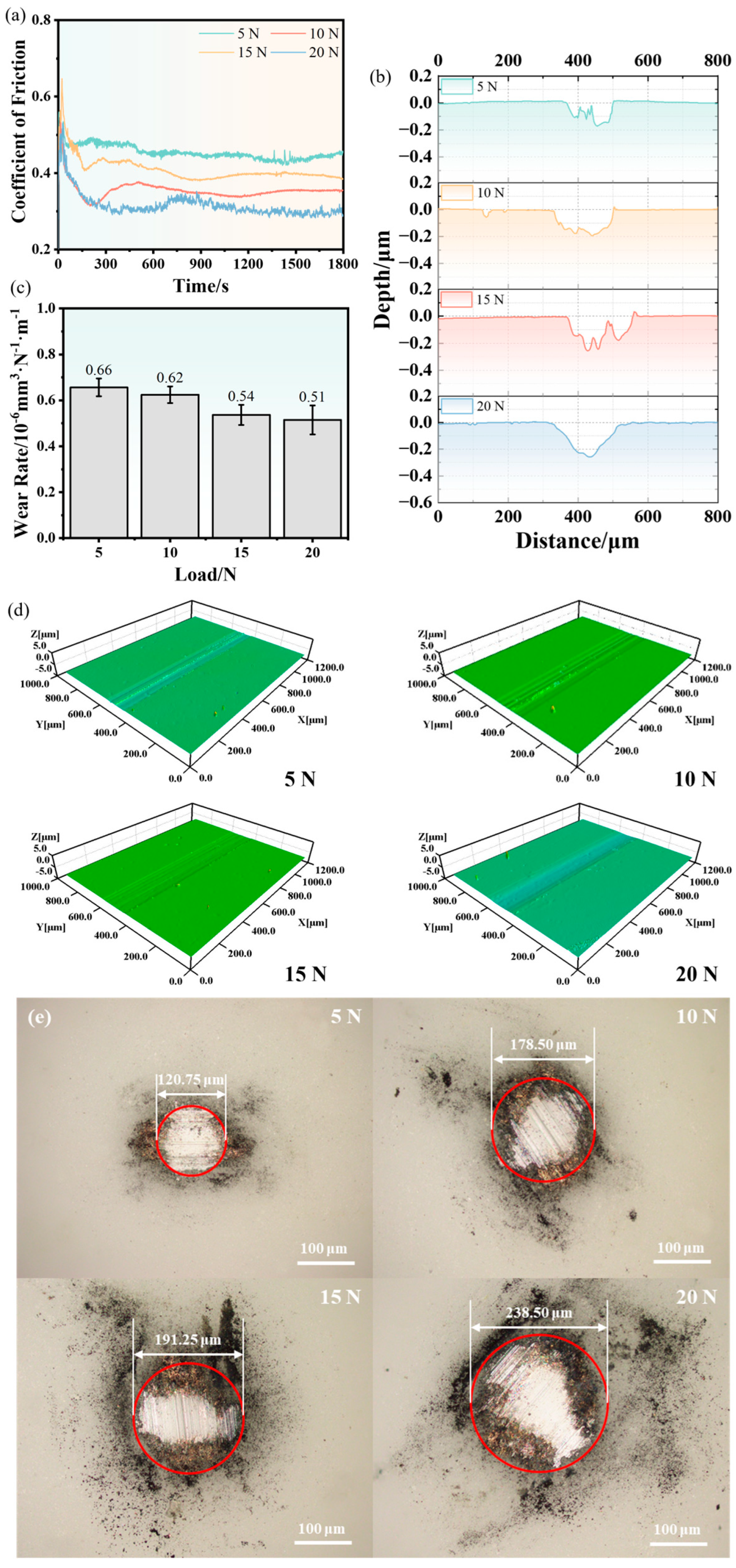
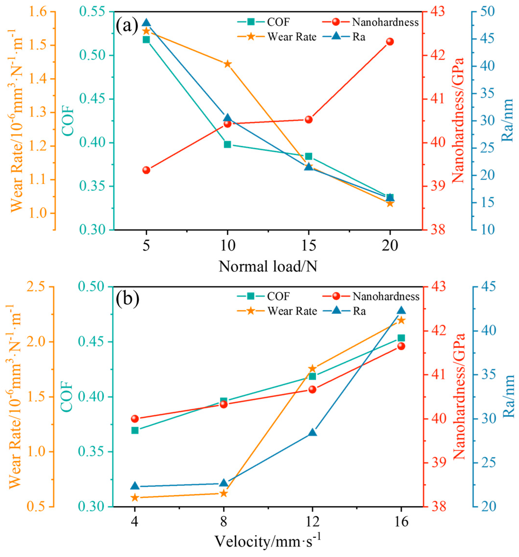
3.3.1. Effect of the Normal Load on the Wear Behavior of TiAlSiN Coating
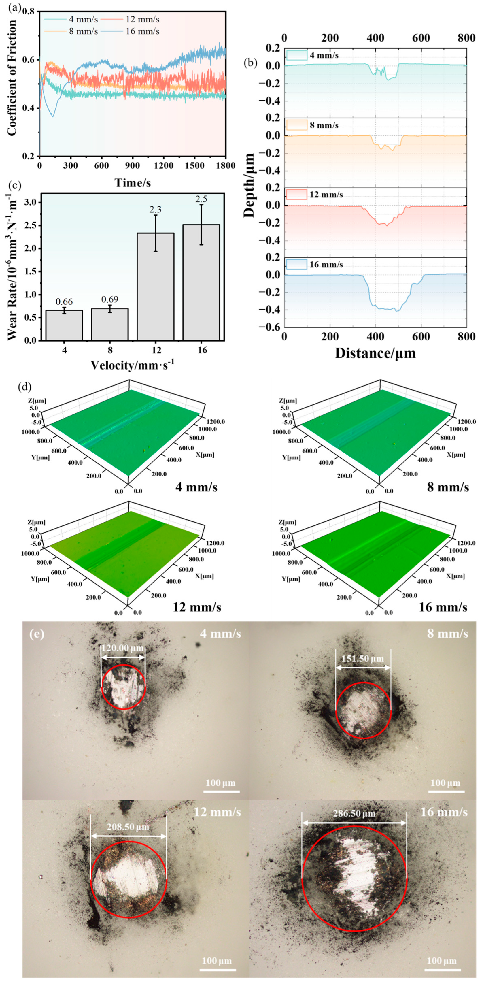
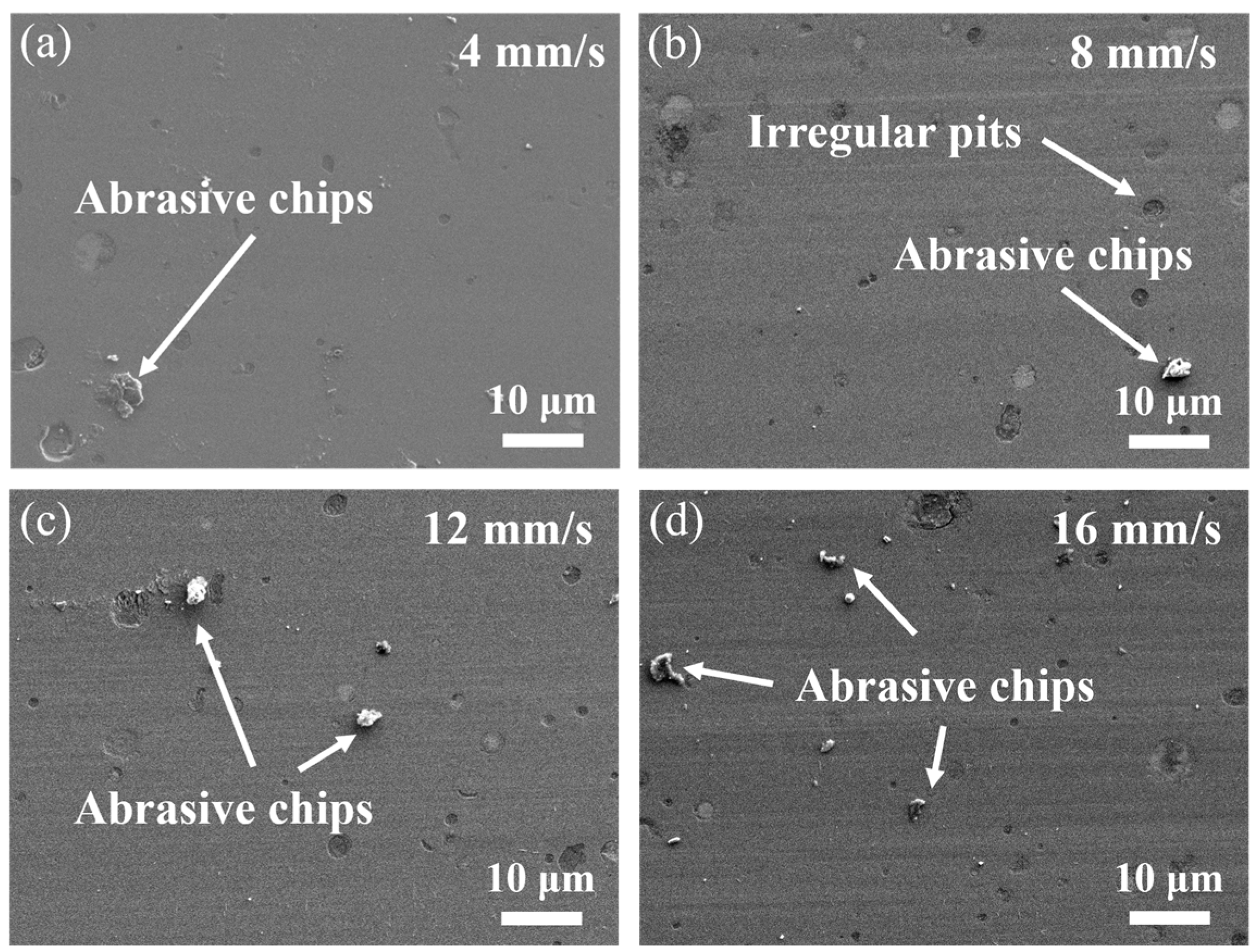
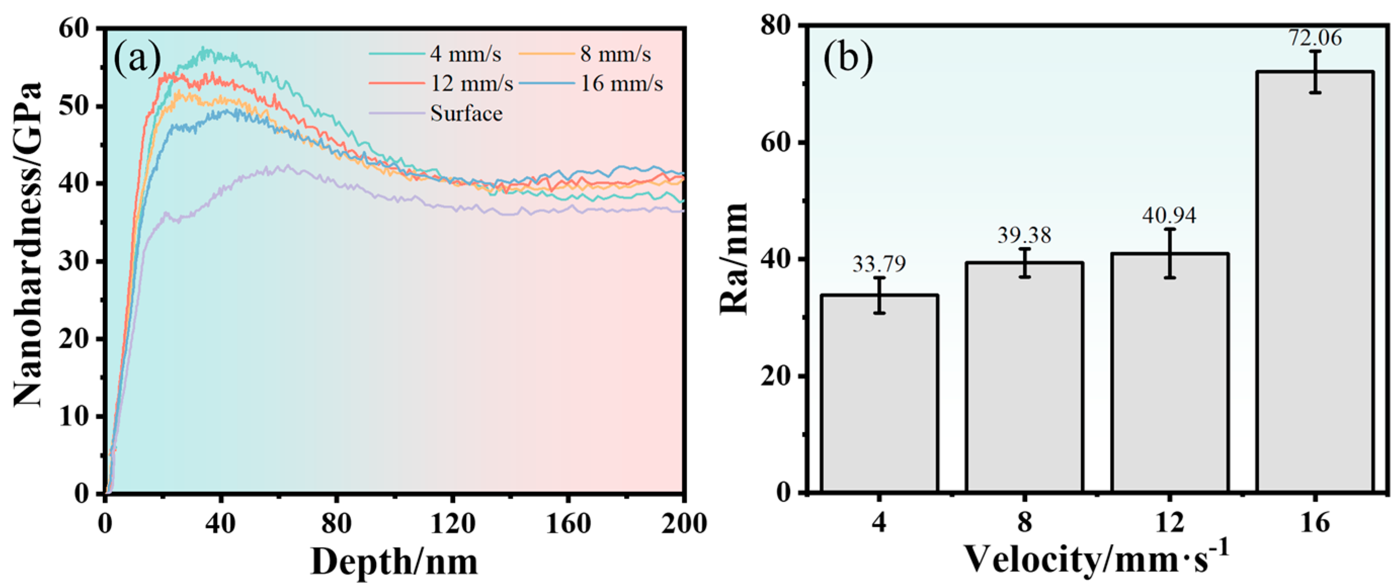
3.3.2. Effect of Velocity on the Wear Behavior of TiAlSiN Coating
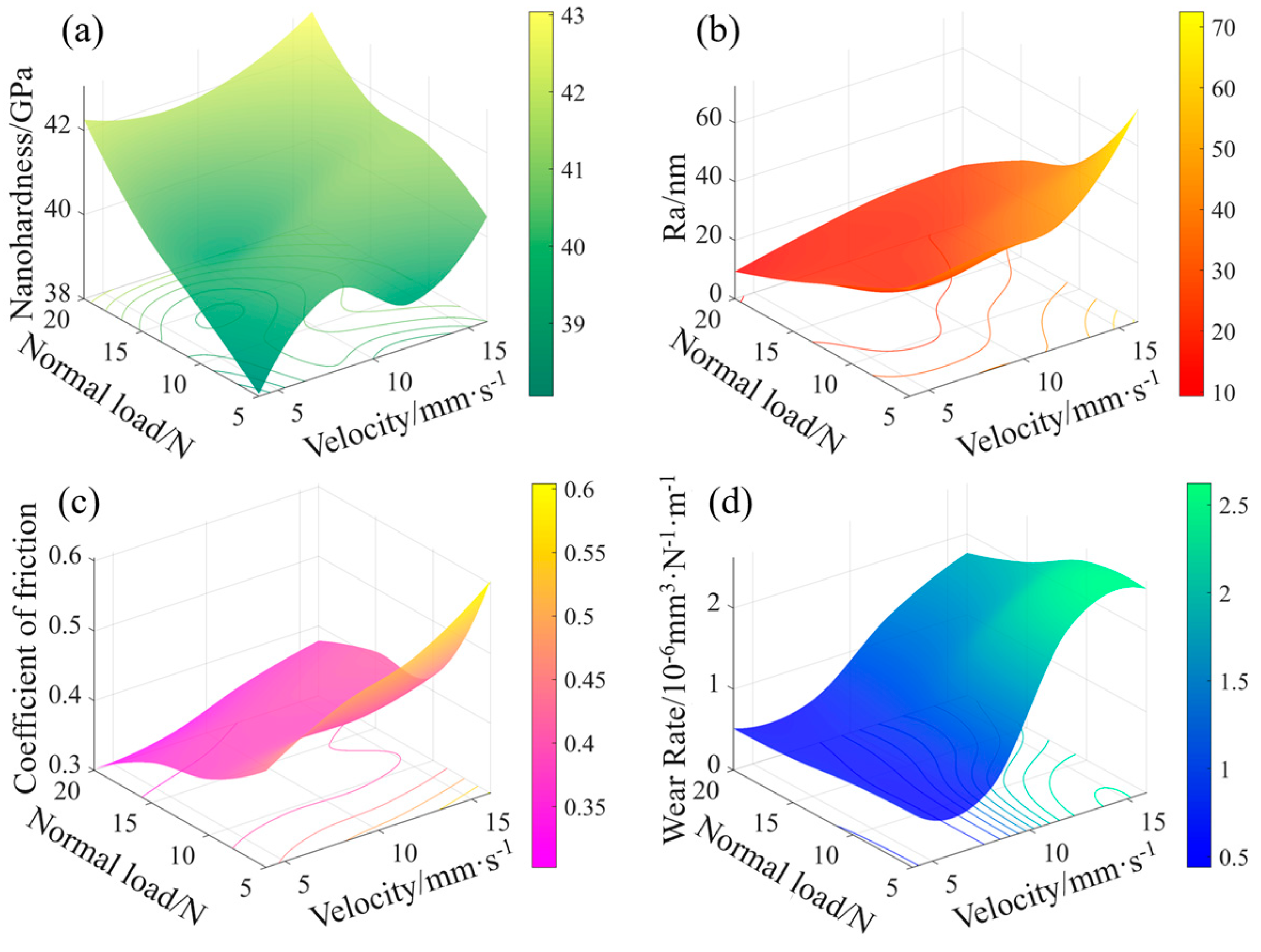
3.3.3. The Wear Behavior under the Load–Velocity Coupling Case
4. Discussion
4.1. Enhanced Strength and Toughness of the Coating
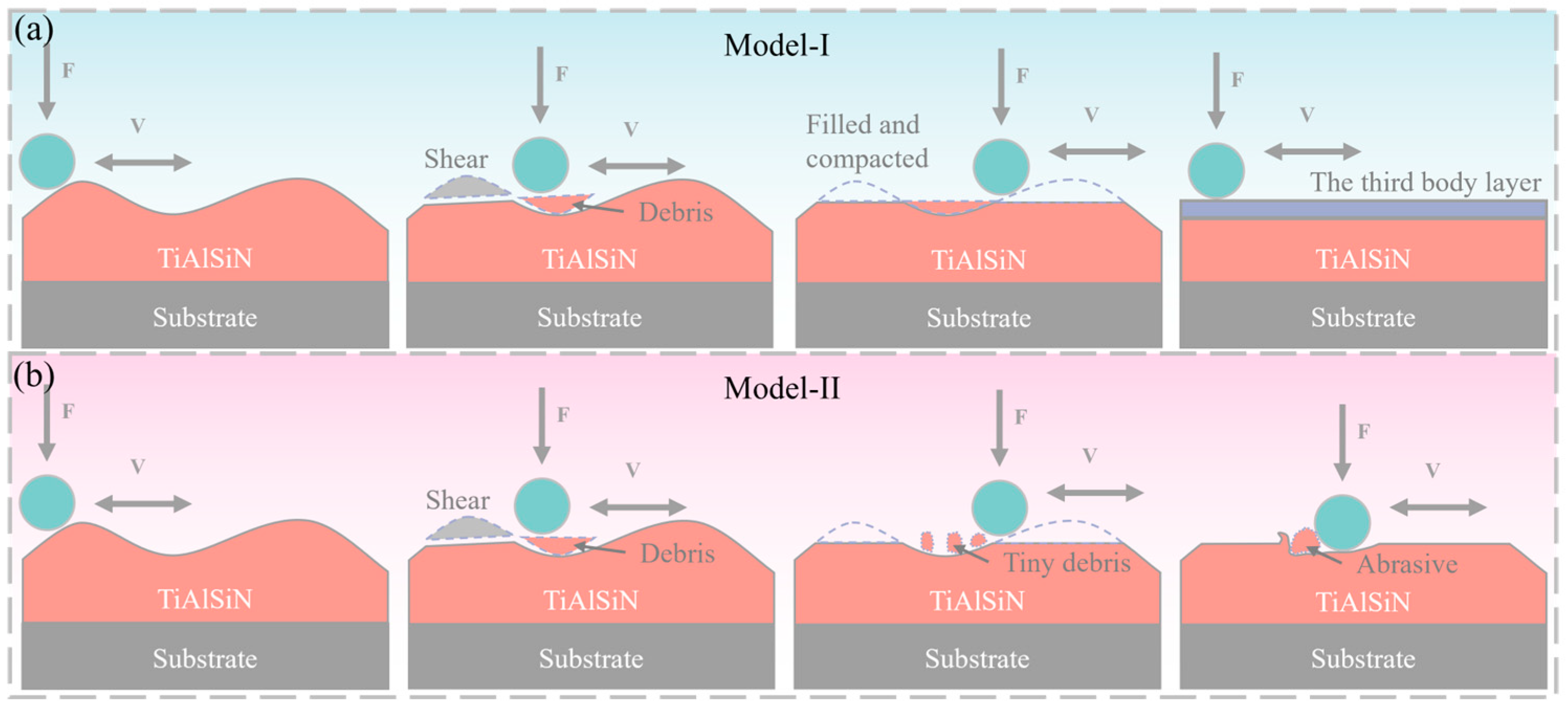
4.2. Third Body Layer and Hard Abrasive Wear Mechanisms
4.3. New Method to Analyze the Wear Mechanism of the TiAlSiN Coating
5. Conclusions
- (1)
- The dense structure and the highly reinforced interfaces of the coating originated from ion bombardment and promoted the bonding, mechanical properties, and wear resistance of the coating to a large extent;
- (2)
- A compressed and lubricated third body layer could be obtained under larger normal loads and resulted in a lower friction coefficient and wear rate, protecting the coating from being more severely worn, while the big-size and hardened abrasives accelerated the wear process under higher velocities;
- (3)
- A full factorial analysis offered good guidance for wear form identification and the wear resistance optimization of TiAlSiN multilayer coating tested in the load–velocity coupling case;
- (4)
- Hard sublayers should be added into multilayer coatings if the wear process conforms more to Model-I, which is probably needed in the conditions of larger normal load and smaller velocity, like sliding bearings. In contrast, more lubricated sublayers should be added, like in the case of high-speed cutting tools.
Supplementary Materials
Author Contributions
Funding
Institutional Review Board Statement
Informed Consent Statement
Data Availability Statement
Conflicts of Interest
References
- Klaasen, H.; Kübarsepp, J. Wear of advanced cemented carbides for metalforming tool materials. Wear 2004, 256, 846–853. [Google Scholar] [CrossRef]
- Pirso, J.; Letunovitš, S.; Viljus, M. Friction and wear behaviour of cemented carbides. Wear 2004, 257, 257–265. [Google Scholar] [CrossRef]
- Roebuck, B.; Almond, E.A. Deformation and fracture processes and the physical metallurgy of WC–Co hardmetals. Int. Mater. Rev. 2013, 33, 90–112. [Google Scholar] [CrossRef]
- Gagg, C.R.; Lewis, P.R. Wear as a product failure mechanism—Overview and case studies. Eng. Fail. Anal. 2007, 14, 1618–1640. [Google Scholar] [CrossRef]
- Santecchia, E.; Hamouda, A.M.S.; Musharavati, F.; Zalnezhad, E.; Cabibbo, M.; Spigarelli, S. Wear resistance investigation of titanium nitride-based coatings. Ceram. Int. 2015, 41, 10349–10379. [Google Scholar] [CrossRef]
- Ou, Y.X.; Wang, H.Q.; Ouyang, X.; Zhao, Y.Y.; Zhou, Q.; Luo, C.W.; Hua, Q.S.; Ouyang, X.P.; Zhang, S. Recent advances and strategies for high-performance coatings. Prog. Mater. Sci. 2023, 136, 101125. [Google Scholar] [CrossRef]
- Sproul, W.D. New Routes in the Preparation of Mechanically Hard Films. Science 1996, 273, 889–892. [Google Scholar] [CrossRef] [PubMed]
- Ma, G.; Wang, L.; Gao, H.; Zhang, J.; Reddyhoff, T. The friction coefficient evolution of a TiN coated contact during sliding wear. Appl. Surf. Sci. 2015, 345, 109–115. [Google Scholar] [CrossRef]
- Łępicka, M.; Grądzka Dahlke, M.; Pieniak, D.; Pasierbiewicz, K.; Kryńska, K.; Niewczas, A. Tribological performance of titanium nitride coatings: A comparative study on TiN-coated stainless steel and titanium alloy. Wear 2019, 422–423, 68–80. [Google Scholar] [CrossRef]
- Zhao, J.; Liu, Z.; Wang, B.; Song, Q.; Ren, X.; Wan, Y. Effects of Al content in TiAlN coatings on tool wear and cutting temperature during dry machining IN718. Tribol. Int. 2022, 171, 107540. [Google Scholar] [CrossRef]
- Antonov, M.; Afshari, H.; Baronins, J.; Adoberg, E.; Raadik, T.; Hussainova, I. The effect of temperature and sliding speed on friction and wear of Si3N4, Al2O3, and ZrO2 balls tested against AlCrN PVD coating. Tribol. Int. 2018, 118, 500–514. [Google Scholar] [CrossRef]
- Huang, B.; Zhou, Q.; An, Q.; Zhang, E.g.; Chen, Q.; Liang, D.d.; Du, H.m.; Li, Z.m. Tribological performance of the gradient composite TiAlSiN coating with various friction pairs. Surf. Coat. Technol. 2022, 429, 127945. [Google Scholar] [CrossRef]
- Liew, W.Y.H.; Lim, H.P.; Melvin, G.J.H.; Dayou, J.; Jiang, Z.T. Thermal stability, mechanical properties, and tribological performance of TiAlXN coatings: Understanding the effects of alloying additions. J. Mater. Res. Technol. 2022, 17, 961–1012. [Google Scholar] [CrossRef]
- Lim, H.P.; Jiang, Z.T.; Melvin, G.J.H.; Nayan, N.; Chee, F.P.; Soon, C.F.; Hassan, N.; Liew, W.Y.H. A systematic investigation of the tribological behaviour of oxides formed on AlSiTiN, CrAlTiN, and CrAlSiTiN coatings. Wear 2023, 512–513, 204552. [Google Scholar] [CrossRef]
- Schulz, W.; Joukov, V.; Köhn, F.; Engelhart, W.; Schier, V.; Schubert, T.; Albrecht, J. The Behavior of TiAlN and TiAlCrSiN Films in Abrasive and Adhesive Tribological Contacts. Coatings 2023, 13, 1603. [Google Scholar] [CrossRef]
- Wang, S.q.; Chen, K.h.; Chen, L.; Zhu, C.j.; Li, P.; Du, Y. Effect of Al and Si additions on microstructure and mechanical properties of TiN coatings. J. Cent. South Univ. 2011, 18, 310–313. [Google Scholar] [CrossRef]
- Das, S.; Guha, S.; Ghadai, R.; Swain, B.P. A comparative analysis over different properties of TiN, TiAlN and TiAlSiN thin film coatings grown in nitrogen gas atmosphere. Mater. Chem. Phys. 2021, 258, 123866. [Google Scholar] [CrossRef]
- Philippon, D.; Godinho, V.; Nagy, P.M.; Delplancke Ogletree, M.P.; Fernández, A. Endurance of TiAlSiN coatings: Effect of Si and bias on wear and adhesion. Wear 2011, 270, 541–549. [Google Scholar] [CrossRef]
- Tillmann, W.; Dildrop, M. Influence of Si content on mechanical and tribological properties of TiAlSiN PVD coatings at elevated temperatures. Surf. Coat. Technol. 2017, 321, 448–454. [Google Scholar] [CrossRef]
- Pei, F.; Liu, H.J.; Chen, L.; Xu, Y.X.; Du, Y. Improved properties of TiAlN coating by combined Si-addition and multilayer architecture. J. Alloys Compd. 2019, 790, 909–916. [Google Scholar] [CrossRef]
- Ma, H.; Miao, Q.; Zhang, G.; Liang, W.; Wang, Y.; Sun, Z.; Lin, H. The influence of multilayer structure on mechanical behavior of TiN/TiAlSiN multilayer coating. Ceram. Int. 2021, 47, 12583–12591. [Google Scholar] [CrossRef]
- Zhao, S.; Zhang, J.; Zhang, Z.; Wang, S.; Zhang, Z. Microstructure and mechanical properties of (Ti,Al,Zr)N/(Ti,Al,Zr,Cr)N films on cemented carbide substrates. Int. J. Miner. Metall. Mater. 2014, 21, 77–81. [Google Scholar] [CrossRef]
- Cao, H.; Yang, J.; Luo, W.; Li, Y.; Qi, F.; Zhao, N.; Lu, L.; Ouyang, X. Influence of film structure on the microstructure and properties of TiAlN coatings on Al-Si alloys. Mater. Charact. 2022, 189, 111996. [Google Scholar] [CrossRef]
- Sampath Kumar, T.; Balasivanandha Prabu, S.; Manivasagam, G.; Padmanabhan, K.A. Comparison of TiAlN, AlCrN, and AlCrN/TiAlN coatings for cutting-tool applications. Int. J. Miner. Metall. Mater. 2014, 21, 796–805. [Google Scholar] [CrossRef]
- Cai, F.; Wang, J.; Zhou, Q.; Zhang, S.; Zheng, J.; Wang, Q.; Kim, K.H. Reduced delamination and improved cutting performance of TiAlSiN multilayer coated cutter by tailoring the adhesion layers and intermediate layers. Wear 2022, 488–489, 204135. [Google Scholar] [CrossRef]
- Li, G.; Li, L.; Han, M.; Luo, S.; Jin, J.; Wang, L.; Gu, J.; Miao, H. The Performance of TiAlSiN Coated Cemented Carbide Tools Enhanced by Inserting Ti Interlayers. Metals 2019, 9, 918. [Google Scholar] [CrossRef]
- Wei, Z.; Xu, X. FEM simulation on impact resistance of surface gradient and periodic layered bionic composites. Compos. Struct. 2020, 247, 112428. [Google Scholar] [CrossRef]
- Kabir, M.S.; Zhou, Z.; Xie, Z.; Munroe, P. Scratch adhesion evaluation of diamond like carbon coatings with alternate hard and soft multilayers. Wear 2023, 518–519, 204647. [Google Scholar] [CrossRef]
- Khadem, M.; Penkov, O.V.; Yang, H.K.; Kim, D.E. Tribology of multilayer coatings for wear reduction: A review. Friction 2017, 5, 248–262. [Google Scholar] [CrossRef]
- Hassani, S.; Klemberg-Sapieha, J.E.; Bielawski, M.; Beres, W.; Martinu, L.; Balazinski, M. Design of hard coating architecture for the optimization of erosion resistance. Wear 2008, 265, 879–887. [Google Scholar] [CrossRef]
- Kolchev, S.; Kolaklieva, L.; Chitanov, V.; Cholakova, T.; Zlatareva, E.; Kovacheva, D.; Atanasova, G.; Kakanakov, R. The Role of Period Modulation on the Structure, Composition and Mechanical Properties of Nanocomposite Multilayer TiAlSiN/AlSiN Coatings. Coatings 2023, 13, 1546. [Google Scholar] [CrossRef]
- He, N.; Li, H.; Ji, L.; Liu, X.; Zhou, H.; Chen, J. High temperature tribological properties of TiAlSiN coatings produced by hybrid PVD technology. Tribol. Int. 2016, 98, 133–143. [Google Scholar] [CrossRef]
- Yue, Q.B.; He, H.B.; Li, H.Y.; Zhang, J.; Li, Y.M.; Ma, L. Research on Friction Characteristics of AlCrN and TiAlSiN Coatings and Properties of Coated Tools. Int. J. Precis. Eng. Manuf. 2019, 20, 1581–1589. [Google Scholar] [CrossRef]
- Mourlas, A.; Psyllaki, P.; Chaliampalias, D.; Vourlias, G.; Kolaklieva, L.; Kakanakov, R. Tribological Behaviour of Gradient TiAlSiN Superhard Coatings. Key Eng. Mater. 2016, 674, 207–212. [Google Scholar] [CrossRef]
- Zhao, F.; Wang, L.; Wang, X. Microstructure and properties of TiAlSiN ultra-hard coatings prepared by plasma immersion ion implantation and deposition with TiAlSi alloy cathodes. Vacuum 2020, 174, 109194. [Google Scholar] [CrossRef]
- Zhao, F.; Ge, Y.; Wang, L.; Wang, X. Tribological and mechanical properties of hardness-modulated TiAlSiN multilayer coatings fabricated by plasma immersion ion implantation and deposition. Surf. Coat. Technol. 2020, 402, 126475. [Google Scholar] [CrossRef]
- Yu, D.; Wang, C.; Cheng, X.; Zhang, F. Microstructure and properties of TiAlSiN coatings prepared by hybrid PVD technology. Thin Solid Film. 2009, 517, 4950–4955. [Google Scholar] [CrossRef]
- Zhirkov, I.; Petruhins, A.; Polcik, P.; Kolozsvári, S.; Rosen, J. Generation of super-size macroparticles in a direct current vacuum arc discharge from a Mo-Cu cathode. Appl. Phys. Lett. 2016, 108, 054103. [Google Scholar] [CrossRef]
- Carvalho, N.J.M.; Zoestbergen, E.; Kooi, B.J.; De Hosson, J.T.M. Stress analysis and microstructure of PVD monolayer TiN and multilayer TiN/(Ti,Al)N coatings. Thin Solid Film. 2003, 429, 179–189. [Google Scholar] [CrossRef]
- Wang, L.; Zhao, S.; Xie, Z.; Huang, L.; Wang, X. MoS2/Ti multilayer deposited on 2Cr13 substrate by PIIID. Nucl. Instrum. Methods Phys. Res. Sect. B 2008, 266, 730–733. [Google Scholar] [CrossRef]
- Xie, Z.W.; Wang, L.P.; Wang, X.F.; Huang, L.; Lu, Y.; Yan, J.C. Influence of high temperature annealing on the structure, hardness and tribological properties of diamond-like carbon and TiAlSiCN nanocomposite coatings. Appl. Surf. Sci. 2011, 258, 1206–1211. [Google Scholar] [CrossRef]
- Wang, Z.; Li, X.; Wang, X.; Cai, S.; Ke, P.; Wang, A. Hard yet tough V-Al-C-N nanocomposite coatings: Microstructure, mechanical and tribological properties. Surf. Coat. Technol. 2016, 304, 553–559. [Google Scholar] [CrossRef]
- Liu, C.; Sun, J. Effect of load on friction and wear behaviors of alumina matrix ceramic guideway materials. J. Alloys Compd. 2018, 743, 268–273. [Google Scholar] [CrossRef]
- Zhu, Y.; Dong, M.; Li, J.; Wang, L. Wear failure mechanism of TiSiN coating at elevated temperatures. Appl. Surf. Sci. 2019, 487, 349–355. [Google Scholar] [CrossRef]
- Shum, P.W.; Xu, Y.F.; Zhou, Z.F.; Cheng, W.L.; Li, K.Y. Study of TiAlSiN coatings post-treated with N and C+N ion implantations. Part 2: The tribological analysis. Wear 2012, 274–275, 274–280. [Google Scholar] [CrossRef]
- Al Rjoub, A.; Cavaleiro, A.; Yaqub, T.B.; Evaristo, M.; Figueiredo, N.M.; Fernandes, F. TiAlSiN(Ag) coatings for high temperature applications: The influence of Ag alloying on the morphology, structure, thermal stability and oxidation resistance. Surf. Coat. Technol. 2022, 442, 128087. [Google Scholar] [CrossRef]
- Hardcastle, F.D.; Wachs, I.E. Raman spectroscopy of chromium oxide supported on Al2O3, TiO2 and SiO2: A comparative study. J. Mol. Catal. 1988, 46, 173–186. [Google Scholar] [CrossRef]
- Andrade, C. The P Value and Statistical Significance: Misunderstandings, Explanations, Challenges, and Alternatives. Indian J. Psychol. Med. 2019, 41, 210–215. [Google Scholar] [CrossRef]
- Voevodin, A.A.; Zabinski, J.S. Supertough wear-resistant coatings with ‘chameleon’ surface adaptation. Thin Solid Film. 2000, 370, 223–231. [Google Scholar] [CrossRef]
- Lü, W.; Li, G.; Zhou, Y.; Liu, S.; Wang, K.; Wang, Q. Effect of high hardness and adhesion of gradient TiAlSiN coating on cutting performance of titanium alloy. J. Alloys Compd. 2020, 820, 153137. [Google Scholar] [CrossRef]
- Cao, X.; He, W.; Liao, B.; Zhou, H.; Zhang, H.; Tan, C.; Yang, Z. Sand particle erosion resistance of the multilayer gradient TiN/Ti coatings on Ti6Al4V alloy. Surf. Coat. Technol. 2019, 365, 214–221. [Google Scholar] [CrossRef]
- Gnyusov, S.F.; Fedin, E.A.; Tarasov, S.Y. The effect of counterbody on tribological adaptation of an electron beam deposited HSS M2 steel coating in a range of sliding speeds and normal loads. Tribol. Int. 2021, 161, 107109. [Google Scholar] [CrossRef]
- Deng, F.; Tsekenis, G.; Rubinstein, S.M. Simple Law for Third-Body Friction. Phys. Rev. Lett. 2019, 122, 135503. [Google Scholar] [CrossRef] [PubMed]
- Niu, Z.; Zhou, W.; Wang, C.; Cao, Z.; Yang, Q.; Fu, X. Fretting wear mechanism of plasma-sprayed CuNiIn coating on Ti-6Al-4V substrate under plane/plane contact. Surf. Coat. Technol. 2021, 408, 126794. [Google Scholar] [CrossRef]


| Parameters | Ti Interlayer | #A TiAlSiN Hard Layer | #B TiAlSiN Soft Layer |
|---|---|---|---|
| Target | Ti | Ti81.76Al4.01Si14.23 | Ti81.76Al4.01Si14.23 |
| Working pressure (Pa) | 0.008 | 0.2 | 0.08 |
| Target current | 0.5A (pulse power supply) | 50A (direct-current power supply) | 50A (direct-current power supply) |
| Implantation voltage (kV) | 15 | 15 | 15 |
| Deposition time in each modulation period (min) | / | 4 | 2 |
| Deposition time in total (min) | 30 | 40 | 20 |
| Experimental Factors | Values | |||
|---|---|---|---|---|
| Normal load/N | 5 | 10 | 15 | 20 |
| Velocity/mm·s−1 | 4\8\12\16 | 4\8\12\16 | 4\8\12\16 | 4\8\12\16 |
| Displacement amplitude/mm | 4 | 4 | 4 | 4 |
| Test time/min | 30 | 30 | 30 | 30 |
| TiAlSiN SUBLAYER | Element Content (at. %) | |||
|---|---|---|---|---|
| Ti | Al | Si | N | |
| #A | 36.08 ± 1.76 | 1.09 ± 0.05 | 3.54 ± 0.17 | 59.30 ± 2.93 |
| #B | 44.06 ± 2.18 | 1.33 ± 0.06 | 2.56 ± 0.12 | 52.05 ± 2.59 |
| Sample | Nanohardness (GPa) | Elastic Modulus (GPa) | H/E* | H3/(E*)2 (GPa) | Adhesion (N) |
|---|---|---|---|---|---|
| TiAlSiN | 37.24 ± 0.96 | 418.52 ± 18.51 | 0.089 | 0.29 | 144 |
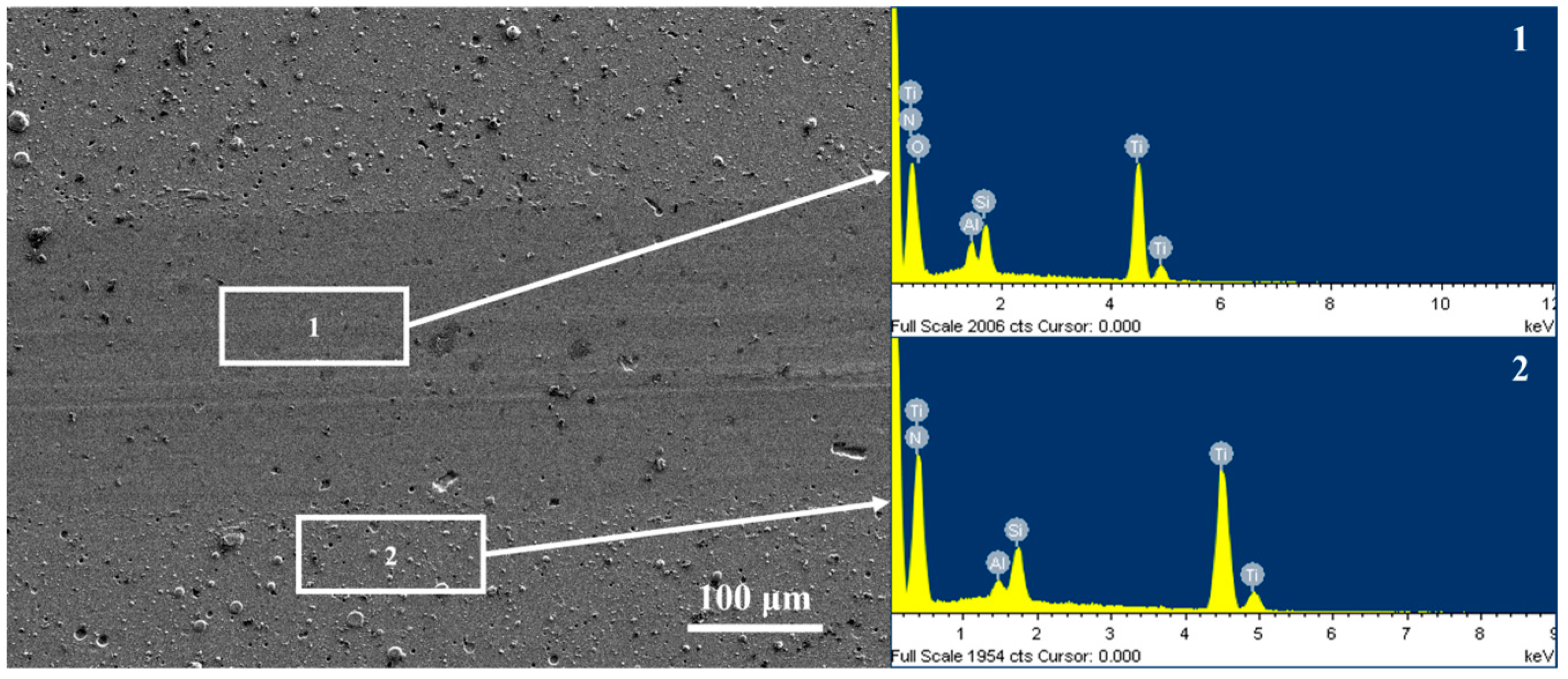
| Sample | Atomic Fraction/% | ||||
|---|---|---|---|---|---|
| Ti | Al | Si | N | O | |
| 1 | 46.06 ± 2.21 | 3.29 ± 0.16 | 6.23 ± 0.32 | 22.53 ± 1.12 | 21.89 ± 1.06 |
| 2 | 47.00 ± 2.34 | 2.02 ± 0.10 | 5.96 ± 0.29 | 45.03 ± 2.24 | - |
Disclaimer/Publisher’s Note: The statements, opinions and data contained in all publications are solely those of the individual author(s) and contributor(s) and not of MDPI and/or the editor(s). MDPI and/or the editor(s) disclaim responsibility for any injury to people or property resulting from any ideas, methods, instructions or products referred to in the content. |
© 2024 by the authors. Licensee MDPI, Basel, Switzerland. This article is an open access article distributed under the terms and conditions of the Creative Commons Attribution (CC BY) license (https://creativecommons.org/licenses/by/4.0/).
Share and Cite
Zhao, F.; Zhu, Z.; Yu, J.; Luo, Z.; Qi, H. Contrast Role of Third Body Layer and Hard Abrasives in the Wear Process of a TiAlSiN Hardness-Modulated Multilayer Coating: A Case Study on the Effect of Normal Load and Velocity. Coatings 2024, 14, 821. https://doi.org/10.3390/coatings14070821
Zhao F, Zhu Z, Yu J, Luo Z, Qi H. Contrast Role of Third Body Layer and Hard Abrasives in the Wear Process of a TiAlSiN Hardness-Modulated Multilayer Coating: A Case Study on the Effect of Normal Load and Velocity. Coatings. 2024; 14(7):821. https://doi.org/10.3390/coatings14070821
Chicago/Turabian StyleZhao, Fan, Zhou Zhu, Jiaxin Yu, Zhiquan Luo, and Huimin Qi. 2024. "Contrast Role of Third Body Layer and Hard Abrasives in the Wear Process of a TiAlSiN Hardness-Modulated Multilayer Coating: A Case Study on the Effect of Normal Load and Velocity" Coatings 14, no. 7: 821. https://doi.org/10.3390/coatings14070821