Article

Advancing Atomic Force Microscopy: Design of Innovative IP-Dip Polymer Cantilevers and Their Exemplary Fabrication via 3D Laser Microprinting

Department of Physics, Faculty of Electrical Engineering and Information Technology, University of Zilina, Univerzitna 1, 01026 Zilina, Slovakia
*
Authors to whom correspondence should be addressed.
Coatings 2024, 14(7), 841; https://doi.org/10.3390/coatings14070841 (registering DOI)
Submission received: 5 June 2024 / Revised: 3 July 2024 / Accepted: 3 July 2024 / Published: 4 July 2024

Abstract

:
This paper presents the design and fabrication of new types of polymer-based cantilevers for atomic force microscopy. The design and fabrication are aimed at the capability of 3D laser microprinting technology based on two-photon polymerization on a standard silicon substrate. IP-Dip commercial material from the Nanoscribe company was used for the fabrication of the designed cantilevers. The fabricated microprinted cantilevers facilitate precise manipulation at the nanoscopic scale, which is essential for studying nanomaterials’ mechanical, electrical, and optical properties. The cantilevers’ flexibility allows for the integration of functional elements such as piezoelectric layers and optical fibers, enabling combined measurements of multiple physical parameters. Various cantilever geometries, including rectangular and V-shaped, are examined, and their resonance frequencies are calculated. The experimental process involves preparing the cantilevers on a silicon substrate and coating them with aluminum for enhanced reflectivity and conductivity. Scanning electron microscope analysis documents the precise form of prepared polymer cantilevers. The functionality of the probes is validated by scanning a step-height standard grating. This study demonstrates the versatility and precision of the fabricated cantilevers, showcasing their potential for large-area scans, living cell investigation, and diverse nanotechnology applications.

1. Introduction

Atomic force microscopy (AFM) enables high-resolution imaging of a sample surface based on atomic interactions between the surface and a scanning probe. This technique is crucial in many nanotechnology applications and offers different modes of scanning and material characterization on the nanoscale. The scanning probe consists of a cantilever base followed by a thin and flexible cantilever, and the most important part is the very sharp AFM tip at the end of the cantilever. Atomic interaction between the AFM tip and sample surface deflects the cantilever. Changes in the positions of the cantilever are optically detected, recorded, and evaluated.
Generally, three basic modes are used in AFM measurements: contact mode, tapping mode, and non-contact mode.
Selecting the appropriate AFM mode is crucial for achieving accurate and reliable measurements. The result is a topographic image of the sample surface with a resolution approaching the size of atoms [1]. Besides the standard surface mapping, modern AFM systems also allow material characterization, magnetic property mapping, and charge distribution in semiconductor materials using specially tailored probes [2]. The most crucial parts for the resolution and properties of AFM microscopy are the cantilever and tip. The quality of AFM cantilevers is evaluated according to several key parameters that determine their suitability for specific applications. The most important parameters of cantilever quality include resonance frequency, elasticity constant, quality factor, cantilever geometry, properties of the material from which the cantilever is made, tip quality (its resistance to damage), friction coefficient (tip surface), chemical resistance, production reproducibility, etc. [3,4,5,6].
The available types of commercial AFM cantilevers and tips enable researchers to select the most suitable probe for the desired application. The two most popular probe materials are monocrystalline silicon and silicon nitride [7]. To provide such a range of tips featuring different functionalities, numerous micro- and nano-fabrication methods and many various materials have been employed for AFM cantilever fabrication, e.g., diamonds [8,9,10,11], metals [12], and various types of photopolymers [13].
Cantilevers made of polymers have unique properties that make them suitable for specific areas of use, primarily in biomedical applications, studying the mechanical properties of soft materials, as chemical sensors, and for high-resolution imaging. It has been shown that the material properties of polymers permit larger frequency bandwidths [14], which are suitable for high-speed imaging [15]. Polymer probes, thanks to their biocompatibility, can be suitable for the investigation of living cells and biological samples. Due to their flexibility, they can be used for measurements of soft and delicate samples, such as polymer gels and biomaterials. It has been shown that the hydrophobic polymeric AFM tips produced by 2PP minimize adhesion forces between the tip and sample during measurements [16,17]. The light weight of polymer cantilevers, compared to silicon ones, can lead to higher sensitivity and, therefore, better resolution. The polymer material, through its mechanical properties and density, determines the stiffness, resonance frequency, and Q-factor of the AFM cantilever [18]. Several different approaches were considered in recent years to prepare AFM cantilevers based on polymers [14,15,16,17].
In this paper, we focus on the novel cantilever and tips prepared from polymer materials typical for 3D laser microprinting (IP-Dip). Fabrication of AFM cantilevers by 3D microprinting allows true 3D control over the resulting cantilever’s shape, tip’s geometry, and aspect ratio [15,17]. This 3D laser microprinting opens a new platform of 3D polymer-based tips tailored to desired applications, as the geometry of the cantilever, shape, and internal structure of the tip can be customized. We offer some basic concepts of cantilevers and tips, as well as their design and fabrication on a standard silicon platform. Prepared AFM probes are finally used for scanning the calibrating grating.

2. Geometry of Cantilevers

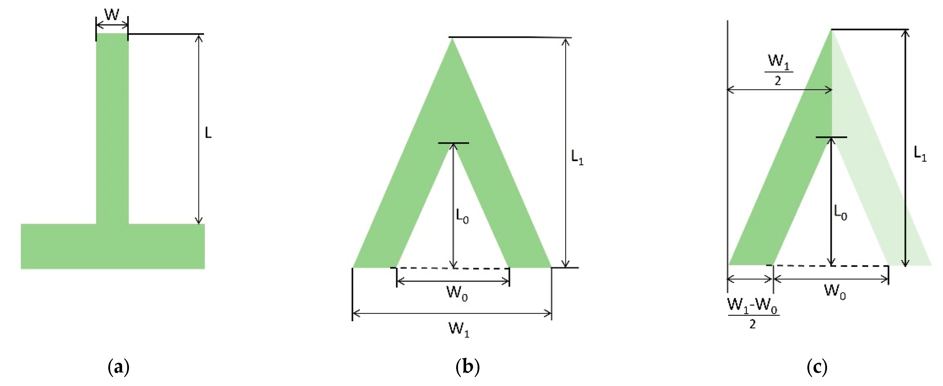
The properties of the cantilevers can then be influenced by their geometry. There are two typical geometries used for AFM cantilevers: simple rectangular geometry and V-shaped geometry (Figure 1) [19].
The stiffness of the cantilever is defined by the force constant k [20,21]. The theoretical expression for the estimation of the force constant in the case of a simple rectangular AFM cantilever is given by the following formula:
k = E W T 3 4 L 3 ,
where E is Young’s modulus, W is the width of the cantilever, T is the thickness, and L is the length of the cantilever [4]. The commonly used AFM cantilevers have force constants in a broad range of 0.01–100 N/m. The “soft” AFM cantilevers, with a k-parameter lower than 0.1 N/m, are primarily used in the contact mode to minimize surface deformation [4]. Another equally important parameter is the resonance frequency. In the simplest case of a rectangular AFM cantilever, neglecting the mass of the AFM tip, the resonance frequency can be calculated using the formula:
f R = T 4 π L 2 E ρ ,
where ρ is the density of the cantilever material. It is evident that the length of the AFM cantilever is the decisive factor for the cantilever’s resonance frequency. A decrease in the length L considerably increases the resonance frequency; however, it also increases the cantilever’s force constant.
Figure 1. Cantilever types according to geometry: (a) simple rectangular; (b) V-shaped geometry; and (c) half of a V-shaped cantilever for analysis.
Coatings 14 00841 g001
AFM probes with a low force constant k and high resonance frequencies are ideal for tapping mode measurements since the AFM probe taps the specimen surface while vibrating at several hundred kHz [9]. We calculated the resonance frequencies for cantilever thicknesses ranging from 6 to 20 µm with a step of 2 µm and cantilever lengths L from 150 to 220 µm with a step of 10 µm. Here, we considered E = 2 GPa (Young’s modulus for IP-Dip ranges from 0.75 GPa to 2.5 GPa depending on the applied laser power during the polymerization process) [22]. As shown in Figure 2, the resonance frequencies of the rectangular cantilever are in the range of several tens of kHz. To achieve resonance frequencies of around 100 kHz, we would have to significantly increase the cantilever thickness or consider the second V-shaped cantilever geometry.
To calculate the resonance frequency of the V-shaped cantilever for AFM microscopy, we employed an analytical solution based on the Rayleigh–Ritz method, as detailed and compared with simulations in the article [23]. The geometry of a V-shaped cantilever can be conceptualized as the difference between two triangular cantilevers (refer to Figure 1b), each with lengths L0 and L1 and widths Wo and W1, respectively. It can be easily concluded that, due to the mirror symmetry of the V-shaped cantilever, it is sufficient to analyze only half of the cantilever, represented by a quadrilateral shape as depicted in Figure 1c. For calculation convenience, it is reasonable to define the width ratio m and the length ratio n of the V-shaped cantilever as follows:
m = W 0 W 1 ,     n = L 0 L 1 .
The resonant frequency of a V-shaped cantilever is then:
f V = T 2 π L 1 2 70 E ρ 3 6 m n + 4 m n 2 m n 3 49 84 p m + 40 m n 6 5 m n 7 .
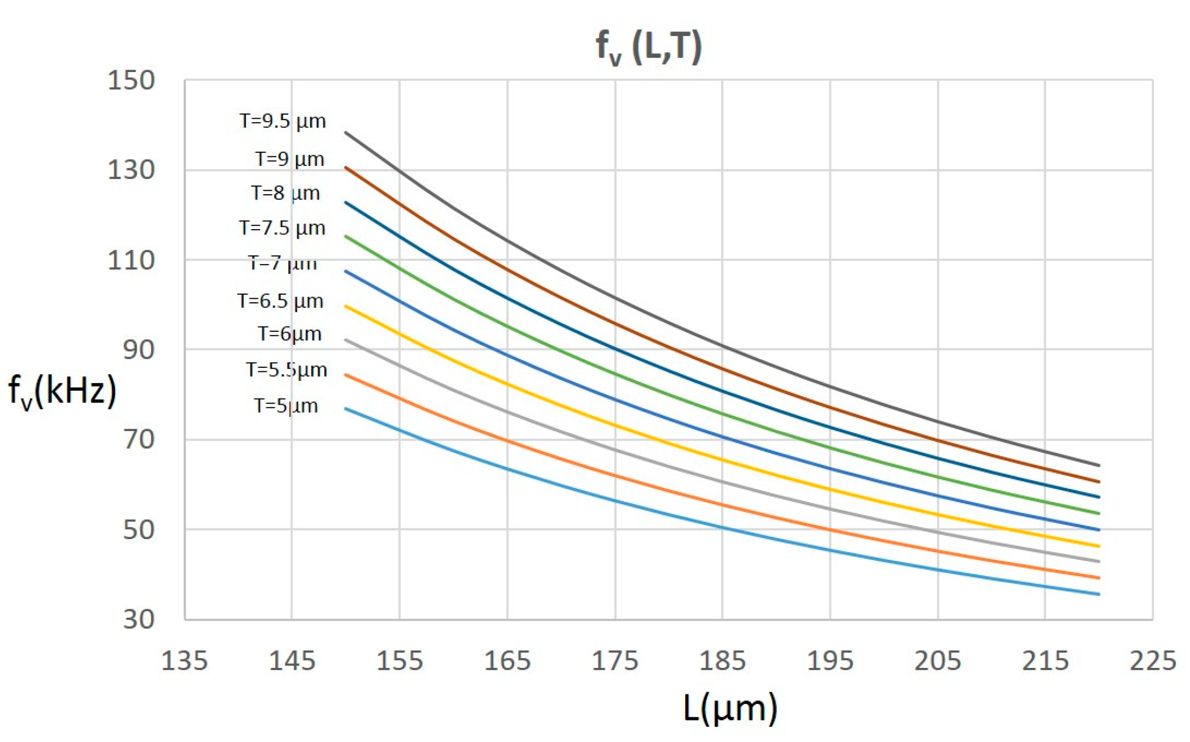
From the given equation, the thickness T and the length L1 exert the greatest influence on the resonance frequency. Considering the technological constraints of direct laser writing (DLW) lithography and the mechanical properties of the IP-Dip polymer, we calculated the resonance frequencies for cantilever thicknesses ranging from 5 to 9 µm with a step of 0.5 µm and cantilever lengths L1 from 150 to 220 µm with a step of 10 µm. We adjusted the parameters m and n to a value of 0.5 (W1 = 100 μm and W0 = 50 μm, where L0 is calculated according to L1). Figure 3 shows the graph of the calculated frequencies. Each line represents the frequencies of the cantilever of a certain thickness, T, dependent on L1. V-shaped cantilevers can reach a higher resonant frequency (compared to rectangular cantilevers with similar dimensions) and exhibit their sensitivity. According to preliminary calculations, selecting an appropriate cantilever geometry allows us to achieve a theoretical resonance frequency ranging from one kilohertz for a rectangular cantilever to approximately 150 kHz for a V-shaped cantilever.

3. Experimental

For the fabrication of the nanoprobes, a commercial 3D laser lithography system, Photonic Professional GT from Nanoscribe GmbH, operating on the principle of two-photon absorption within a polymer matrix, was used. The dielectric polymer material IP-Dip, known for its suitable mechanical and optical properties, was employed in this process [24,25,26,27]. The microprinted cantilevers produced through this method facilitate highly precise manipulation at the nanoscopic scale, including the manipulation of molecules and nanoparticles. These cantilevers can be used to study nanomaterials in detail, including their mechanical, electrical, and optical properties. Additionally, the flexibility in the design makes it possible to create cantilevers with integrated functional elements, such as piezoelectric layers or optical fibers, which enable combined measurements of multiple physical parameters.
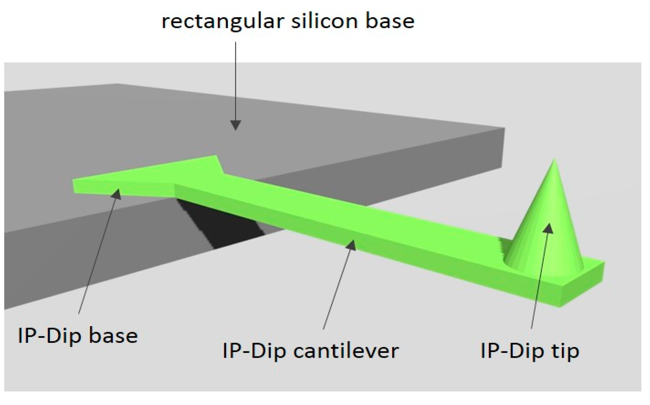
A silicon wafer in the shape of a rectangle with dimensions of 3 × 5 mm was used as the base or chip of the AFM probe. A cantilever with a tip was prepared at its edge, as depicted in Figure 4. To ensure a firm connection of the cantilever to the chip, one end of the cantilever is widened, as shown in the IP-Dip base in Figure 4. Prior to the microprinting process, the silicon wafer was treated with isopropyl alcohol (IPA) to remove impurities from its surface. Subsequently, the liquid polymer IP-Dip was applied to the edge of the silicon wafer.
The lithography process was divided into three steps. In the first step, we printed the IP-Dip base on the silicon substrate (Figure 4). The femtosecond laser beam reflection from the silicon substrate caused the standing wave phenomenon with variable laser power in the vertical direction. This was reflected in the nitrogen being released from the polymer in the form of bubbles in the layers with higher laser power. Therefore, we had to adjust the printing on this substrate by reducing the laser power to P = 24 mW. Subsequently, we focused on the preparation of the cantilever-protruding part. Since the cantilever was printed without supports, we maximized the scanning speed up to 40,000 µm/s and the laser power to P = 36 mW, setting the slicing structure to 200 nm. In the third step, the tip was prepared at the end of the cantilever. To prepare the tip with the smallest possible diameter, we used laser power P = 18 mW and a slicing distance of 100 nm.
Following the lithography process, the structure was developed in Propylene Glycol Mono Methyl Ether Acetate (PGMAE) and then rinsed in IPA. To enhance the reflectivity of the cantilever surface for AFM analysis, the backside of the cantilever was coated with aluminum using the K975X Turbo-Pumped Thermal Evaporator. Another advantage of this cantilever metallization is the improved conductivity, as the cantilevers prepared from polymers are prone to electrostatic charge accumulation, and a charged AFM tip results in distortion of the images.

4. Results and Discussion

Using 3D microprinting, we achieved high-quality polymer rectangular cantilevers prepared on a silicon substrate. The prepared cantilevers were investigated using a scanning electron microscope (SEM) (Tescan Lyra3). The top view of the entire cantilever can be seen in Figure 5a. On the detailed view of the tip in Figure 5b, the 100 nm slicing effect on the tip height can be observed. The radius of the prepared tip was 200 nm. The repeatability of the process is documented in Figure 5c, which shows a series of prepared cantilevers on a silicon substrate. The prepared cantilevers reflect the designed geometry very well, featuring a very sharp tip reaching hundreds of nanometers.
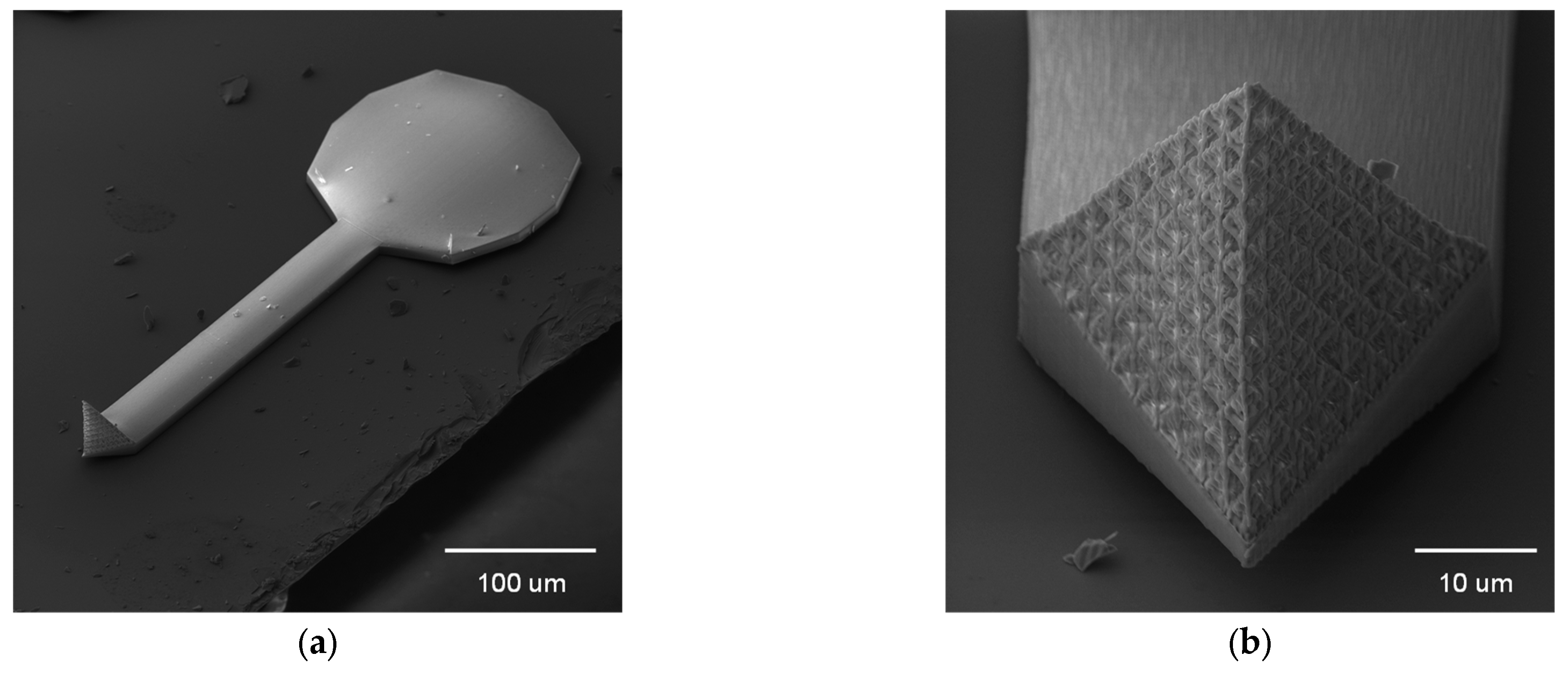
In addition, to demonstrate the capabilities of the microprinting system, we prepared other models of AFM cantilevers (see Figure 6a). To ensure better attachment of the cantilever to the silicon wafer, we enlarged the IP-Dip base. As a very promising area of AFM probe printing, we also demonstrate controlled microstructure architecture (CMA) design [28]. We prepared an exemplary tetrahedron skeleton as the CMA tip (Figure 6b).
The functionality of the probe was examined by scanning the Step Height Standard calibrating grating from Applied NanoStructures, Inc., Mountain View, CA, USA, with a height of 100 nm and a pitch of 10 μm. The AFMWorkshop HR-2D atomic force microscope in contact mode was used for the experimental characterization of prepared cantilevers. After aligning the necessary AFM components, we detected the reflection of light from the surface of the cantilever using a four-quadrant photodetector, which is divided into four sections. The control software measures two channels: The top–bottom channel (T-B) and the Z-Drive channel. Channels were measured in parallel, which gives us two different data sets for the same investigated area. The T-B signal was obtained from the difference in light intensity detected by the upper and lower parts of the detector (as illustrated in Figure 7a). The T-B signal provides a more plastic interpretation of the measured sample surface. The z-drive channel obtained data from piezo-scanner positions (Figure 7b). It allows us to measure and evaluate the vertical profile of the sample. Figure 7c shows the height profile along line 1 (from Figure 7b). The obtained data were processed in Gwyddion software, version 2.61 and the measured profile shows promising agreement with the parameters of the calibration sample with a 15 nm deviation in the vertical direction.

5. Conclusions

This study demonstrates new types of AFM probes prepared by 3D laser microprinting. The advantage of this type of preparation of cantilevers and tips is the great variability of their shapes, which leads to different stiffness and resonance frequencies focused on a broad spectrum of applications. We designed the full polymer cantilevers with nanoconical tips, and we exemplary fabricated them using 3D microprinting single-process technology. In this paper, we have also outlined other possible cantilever and tip designs, such as those with controlled microstructure architecture (CMA). The quality of the prepared probes was examined using SEM, and their functionality was validated by scanning a Step Height Standard grating by AFM. The results demonstrated promising agreement with the expected parameters with a 15 nm deviation in the vertical direction, showcasing the excellent potential of these cantilevers for high-resolution imaging and precise surface characterization on large areas.

Author Contributions

Conceptualization, P.G., D.J., and D.P.; methodology, P.G. and D.J.; validation, S.B. and M.G.; formal analysis, P.G. and D.J.; investigation, S.B.; resources, P.G.; data curation, M.G.; writing—original draft preparation, P.G.; writing—review and editing, D.J.; visualization, P.G.; supervision, D.P.; project administration, D.P.; funding acquisition, D.P. All authors have read and agreed to the published version of the manuscript.

Funding

This work was supported by the Slovak National Grant Agency under project No. VEGA 1/0363/22 and the Slovak Research and Development Agency under project No. APVV 20-0264.

Institutional Review Board Statement

Not applicable.

Informed Consent Statement

Not applicable.

Data Availability Statement

The original contributions presented in the study are included in the article; further inquiries can be directed to the corresponding author.

Conflicts of Interest

The authors declare no conflicts of interest.

References

  1. Méndez-Vilas, A.; González-Martín, M.; Nuevo, M. Optical Interference Artifacts in Contact Atomic Force Microscopy Images. Ultramicroscopy 2002, 92, 243–250. [Google Scholar] [CrossRef] [PubMed]
  2. You, H.; Yu, L. Investigation of the Image Contrast of Tapping-Mode Atomic Force Microscopy Using Protein-Modified Cantilever Tips. Biophys. J. 1997, 73, 3299–3308. [Google Scholar] [CrossRef] [PubMed]
  3. Sedin, D.L.; Rowlen, K.L. Influence of Tip Size on AFM Roughness Measurements. Appl. Surf. Sci. 2001, 182, 40–48. [Google Scholar] [CrossRef]
  4. Sader, J.E.; Chon, J.W.M.; Mulvaney, P. Calibration of Rectangular Atomic Force Microscope Cantilevers. Rev. Sci. Instrum. 1999, 70, 3967–3969. [Google Scholar] [CrossRef]
  5. Siedle, P.; Butt, H.-J.; Bamberg, B.; Wang, D.N.; Kühlbrandt, W.; Zach, J.; Haider, M. Determining the Form of Atomic Force Microscope Tips. In X-Ray Optics and Microanalysis 1992, Proceedings of the 13th INT Conference, Manchester, UK, 31 August–4 September 1992; CRC Press: Boca Raton, FL, USA, 1993; ISBN 978-1-00-306296-7. [Google Scholar]
  6. Ke, S.H.; Uda, T.; Štich, I.; Terakura, K. Effect of Tip Morphology on AFM Images. Appl. Phys. A 2001, 72, S63–S66. [Google Scholar] [CrossRef]
  7. Grow, R.J.; Minne, S.C.; Manalis, S.R.; Quate, C.F. Silicon Nitride Cantilevers with Oxidation-Sharpened Silicon Tips for Atomic Force Microscopy. J. Microelectromechanical Syst. 2002, 11, 317–321. [Google Scholar] [CrossRef]
  8. Kulisch, W.; Malave, A.; Lippold, G.; Scholz, W.; Mihalcea, C.; Oesterschulze, E. Fabrication of Integrated Diamond Cantilevers with Tips for SPM Applications. Diam. Relat. Mater. 1997, 6, 906–911. [Google Scholar] [CrossRef]
  9. Hantschel, T.; Slesazeck, S.; Niedermann, P.; Eyben, P.; Vandervorst, W. Integrating Diamond Pyramids into Metal Cantilevers and Using Them as Electrical AFM Probes. Microelectron. Eng. 2001, 57–58, 749–754. [Google Scholar] [CrossRef]
  10. Salvadori, M.C.; Fritz, M.C.; Carraro, C.; Maboudian, R.; Monteiro, O.R.; Brown, I.G. Characterization of AFM Cantilevers Coated with Diamond-like Carbon. Diam. Relat. Mater. 2001, 10, 2190–2194. [Google Scholar] [CrossRef]
  11. Givargizov, E.I.; Stepanova, A.N.; Mashkova, E.S.; Molchanov, V.A.; Shi, F.; Hudek, P.; Rangelow, I.W. Ultrasharp Diamond-Coated Silicon Tips for Scanning-Probe Devices. Microelectron. Eng. 1998, 41–42, 499–502. [Google Scholar] [CrossRef]
  12. Sorensen, A.H.; Hvid, U.; Mortensen, M.W.; Morch, K.A. Preparation of Platinum/Iridium Scanning Probe Microscopy Tips. Rev. Sci. Instrum. 1999, 70, 3059–3067. [Google Scholar] [CrossRef]
  13. Akiyama, T.; Staufer, U.; de Rooij, N.F.; Howald, L.; Scandella, L. Lithographically Defined Polymer Tips for Quartz Tuning Fork Based Scanning Force Microscopes. Microelectron. Eng. 2001, 57–58, 769–773. [Google Scholar] [CrossRef]
  14. Göring, G.; Dietrich, P.-I.; Blaicher, M.; Sharma, S.; Korvink, J.G.; Schimmel, T.; Koos, C.; Hölscher, H. Tailored Probes for Atomic Force Microscopy Fabricated by Two-Photon Polymerization. Appl. Phys. Lett. 2016, 109, 063101. [Google Scholar] [CrossRef]
  15. Alsharif, N.; Burkatovsky, A.; Lissandrello, C.; Jones, K.M.; White, A.E.; Brown, K.A. Design and Realization of 3D Printed AFM Probes. Small 2018, 14, e1800162. [Google Scholar] [CrossRef] [PubMed]
  16. Kim, J.M.; Muramatsu, H. Two-Photon Photopolymerized Tips for Adhesion-Free Scanning-Probe Microscopy. Nano Lett. 2005, 5, 309–314. [Google Scholar] [CrossRef] [PubMed]
  17. Kim, W.-S.; Park, K.-M.; Park, J.J.; Chang, S.-M.; Kim, I.-H.; Muramatsu, H.; Kim, J.M. Polymer Tips for Application of Atomic Force Microscopy. Curr. Appl. Phys. 2007, 7, 528–531. [Google Scholar] [CrossRef]
  18. Yasumura, K.Y.; Stowe, T.D.; Chow, E.M.; Pfafman, T.; Kenny, T.W.; Stipe, B.C.; Rugar, D. Quality Factors in Micron- and Submicron-Thick Cantilevers. J. Microelectromechanical Syst. 2000, 9, 117–125. [Google Scholar] [CrossRef]
  19. Tortonese, M. Cantilevers and Tips for Atomic Force Microscopy. IEEE Eng. Med. Biol. Mag. 1997, 16, 28–33. [Google Scholar] [CrossRef]
  20. Neumeister, J.M.; Ducker, W.A. Lateral, Normal, and Longitudinal Spring Constants of Atomic Force Microscopy Cantilevers. Rev. Sci. Instrum. 1994, 65, 2527–2531. [Google Scholar] [CrossRef]
  21. Hazel, J.L.; Tsukruk, V.V. Spring Constants of Composite Ceramic/Gold Cantilevers for Scanning Probe Microscopy. Thin Solid Film. 1999, 339, 249–257. [Google Scholar] [CrossRef]
  22. Lemma, E.D.; Rizzi, F.; Dattoma, T.; Spagnolo, B.; Sileo, L.; Qualtieri, A.; De Vittorio, M.; Pisanello, F. Mechanical Properties Tunability of Three-Dimensional Polymeric Structures in Two-Photon Lithography. IEEE Trans. Nanotechnol. 2016, 16, 23–31. [Google Scholar] [CrossRef]
  23. Efimov, T.A.; Rassolov, E.A.; Andryukov, B.G.; Zaporozhets, T.S.; Romashko, R.V. Calculation of Resonant Frequencies of Silicon AFM Cantilevers. J. Phys. Conf. Ser. 2020, 1439, 012006. [Google Scholar] [CrossRef]
  24. Durisova, J.; Pudis, D.; Goraus, M.; Gaso, P. IP-Dip Photoresist Surfaces for Photonic Applications Prepared by Laser Lithography and Studied by AFM. Appl. Surf. Sci. 2018, 461, 108–112. [Google Scholar] [CrossRef]
  25. Goraus, M.; Martincek, I. Optimalisation of 3D Laser Printing Process for Highly Reflective Polymer Surfaces. In Proceedings of the 22nd Polish-Slovak-Czech Optical Conference on Wave and Quantum Aspects of Contemporary Optics, Wojanow, Poland, 5–9 September 2022; SPIE: Bellingham, WA, USA, 2022; Volume 12502, pp. 117–120. [Google Scholar] [CrossRef]
  26. Micek, P.; Pudis, D.; Gaso, P.; Durisova, J.; Jandura, D. Microring Zone Structure for Near-Field Probes. Coatings 2021, 11, 1363. [Google Scholar] [CrossRef]
  27. Suslik, L.; Gaso, P.; Jandura, D.; Pudis, D. 3D Photonic Structures for Optoelectronic Applications. In Proceedings of the 22nd Polish-Slovak-Czech Optical Conference on Wave and Quantum Aspects of Contemporary Optics, Wojanow, Poland, 5–9 September 2022; SPIE: Bellingham, WA, USA, 2022; Volume 12502, pp. 112–116. [Google Scholar] [CrossRef]
  28. Sun, L.; Gu, H.; Liu, X.; Ni, H.; Li, Q.; Zeng, Y.; Chang, N.; Zhang, D.; Chen, H.; Li, Z.; et al. 3D-Printed Cellular Tips for Tuning Fork Atomic Force Microscopy in Shear Mode. Nat. Commun. 2020, 11, 5732. [Google Scholar] [CrossRef] [PubMed]
Figure 2. Resonant frequencies of rectangular cantilevers as a function of length at variable thickness.
Coatings 14 00841 g002
Figure 3. Resonant frequencies of a V-shaped cantilever as a function of length and thickness.
Coatings 14 00841 g003
Figure 4. Illustration of designed deployment of parts of IP-Dip cantilever.
Coatings 14 00841 g004
Figure 5. SEM images of all-polymer cantilevers with the nanoconical shape of a tip prepared from IP-Dip material: (a) overall top view of a cantilever with a tip; (b) detailed view of a nanoconical tip of a cantilever; and (c) side view of three cantilevers with a nanoconical shape of the tip prepared on the edge of Si substrate.
Coatings 14 00841 g005
Figure 6. SEM images of all-polymer cantilevers with the pyramidal shape of a tip prepared from IP-Dip material: (a) overall view of the cantilever with enlarged base; (b) detailed view of the CMA tip as a tetrahedron skeleton shape with triangular meshing.
Coatings 14 00841 g006
Figure 7. (a) AFM amplitude image of calibrating grating obtained using a prepared IP-Dip cantilever with a nanoconical shape of the tip; (b) AFM image obtained from Z-drive scanning; and (c) corresponding height profile along line 1.
Coatings 14 00841 g007
Disclaimer/Publisher’s Note: The statements, opinions and data contained in all publications are solely those of the individual author(s) and contributor(s) and not of MDPI and/or the editor(s). MDPI and/or the editor(s) disclaim responsibility for any injury to people or property resulting from any ideas, methods, instructions or products referred to in the content.