Article

Enhancing Wear Resistance of A390 Aluminum Alloy: A Comprehensive Evaluation of Thermal Sprayed WC, CrC, and Al2O3 Coatings

Interdisciplinary Major of Maritime AI Convergence, Department of Ocean Advanced Materials Convergence Engineering, National Korea Maritime and Ocean University, Busan 49112, Republic of Korea
*
Author to whom correspondence should be addressed.
Coatings 2024, 14(7), 853; https://doi.org/10.3390/coatings14070853 (registering DOI)
Submission received: 11 June 2024 / Revised: 27 June 2024 / Accepted: 4 July 2024 / Published: 8 July 2024
(This article belongs to the Special Issue Additive Manufacturing of Metallic Components for Hard Coatings)

Abstract

:
This study comparatively analyzed the wear characteristics and adhesion properties of 86WC–10Co–4Cr (WC) coatings deposited using the high velocity oxygen fuel process and 75Cr3C2–25NiCr (CrC) and Al2O3–3TiO2 (Al2O3) coatings deposited using the atmospheric plasma spray process on an A390 aluminum alloy substrate. The adhesion strength and wear test results demonstrated that the WC coating exhibited superior wear resistance. In contrast, the CrC and Al2O3 coatings showed lower adhesion properties and unstable frictional variations due to a higher number of defects compared to the WC coating. The WC coating layer, protected by WC particles, exhibited minimal damage and a low wear rate, followed by CrC and Al2O3. Ultimately, WC coating is highlighted as the optimal choice to enhance the wear resistance of A390 aluminum alloy.

1. Introduction

Aluminum alloys are widely used in the automotive, marine, and aerospace industries due to their high strength, excellent thermal conductivity, and corrosion resistance [1,2]. These properties make aluminum alloys ideal for manufacturing lightweight and fuel-efficient vehicles, as well as for constructing durable marine structures and high-performance aerospace components [3,4,5,6]. The inherent light weight of aluminum, combined with its ability to resist corrosion, significantly enhances the lifespan and performance of parts exposed to harsh environments [1,2,3,4,5,6].
However, the inherently low hardness and poor wear resistance of aluminum alloys restrict their use in extreme environments characterized by high temperatures and friction. For instance, in automotive engines and aerospace turbines, components are subjected to severe mechanical stresses and thermal loads that can lead to rapid wear and tear. This necessitates frequent maintenance and part replacements, thereby increasing operational costs and downtime. Therefore, enhancing the wear resistance of aluminum alloys through surface treatments is essential for their use in high-performance components [4,5].
One of the most effective methods to improve surface properties is surface coating using materials with excellent mechanical properties [7,8]. Thermal spray methods such as flame spray, high velocity oxygen fuel (HVOF), atmospheric plasma arc spray (APS), and wire arc spray (WAS) are primarily used for superior surface protection [8,9]. These methods are applied across various industries by selecting materials that suit the characteristics of each process. Among them, APS and HVOF have been the most widely used due to their ability to generate dense coating layers using plasma at 20,000 degrees Celsius or high-temperature supersonic gas streams. These processes allow for the use of metals and ceramics, providing a wide range of material choices, low porosity, high wear resistance, and strong adhesion [10,11,12,13,14,15,16].
APS and HVOF processes typically employ oxides or carbides due to their high melting points. Oxides such as Al2O3 and carbides like WC and Cr3C2 are combined with metals like Co, Ni, and Cr to protect the substrate surface. These materials are favored in APS and HVOF coatings due to their low oxygen content in the coating layer, short reaction times resulting in low porosity, and excellent adhesion properties. Consequently, they are widely used in components requiring high wear resistance and corrosion resistance [5,17,18].
Despite ongoing efforts, the inherent limitations of aluminum alloys due to their low surface hardness and wear resistance persist [19,20]. Existing studies have attempted to address these issues through various surface treatment technologies, but most have failed to fully elucidate the wear resistance mechanisms of oxide and carbide coatings. For instance, while methods such as laser cladding can enhance surface hardness and wear resistance, they face issues such as limited application range and difficulty in maintaining consistent quality [21].
To date, there has been little research on the wear resistance mechanisms of ceramic coatings on aluminum surfaces. Therefore, this study comparatively analyzed the wear characteristics of 86WC–10Co–4Cr coatings applied using the HVOF process and 75Cr3C2–25NiCr and Al2O3–3TiO2 coatings applied using the APS process. This study presents coating materials and processes with the potential to significantly enhance the wear resistance of aluminum alloys, providing valuable insights for the development of high-performance components in various industrial applications and demonstrating the potential to improve the durability of the alloys.

2. Materials and Methods
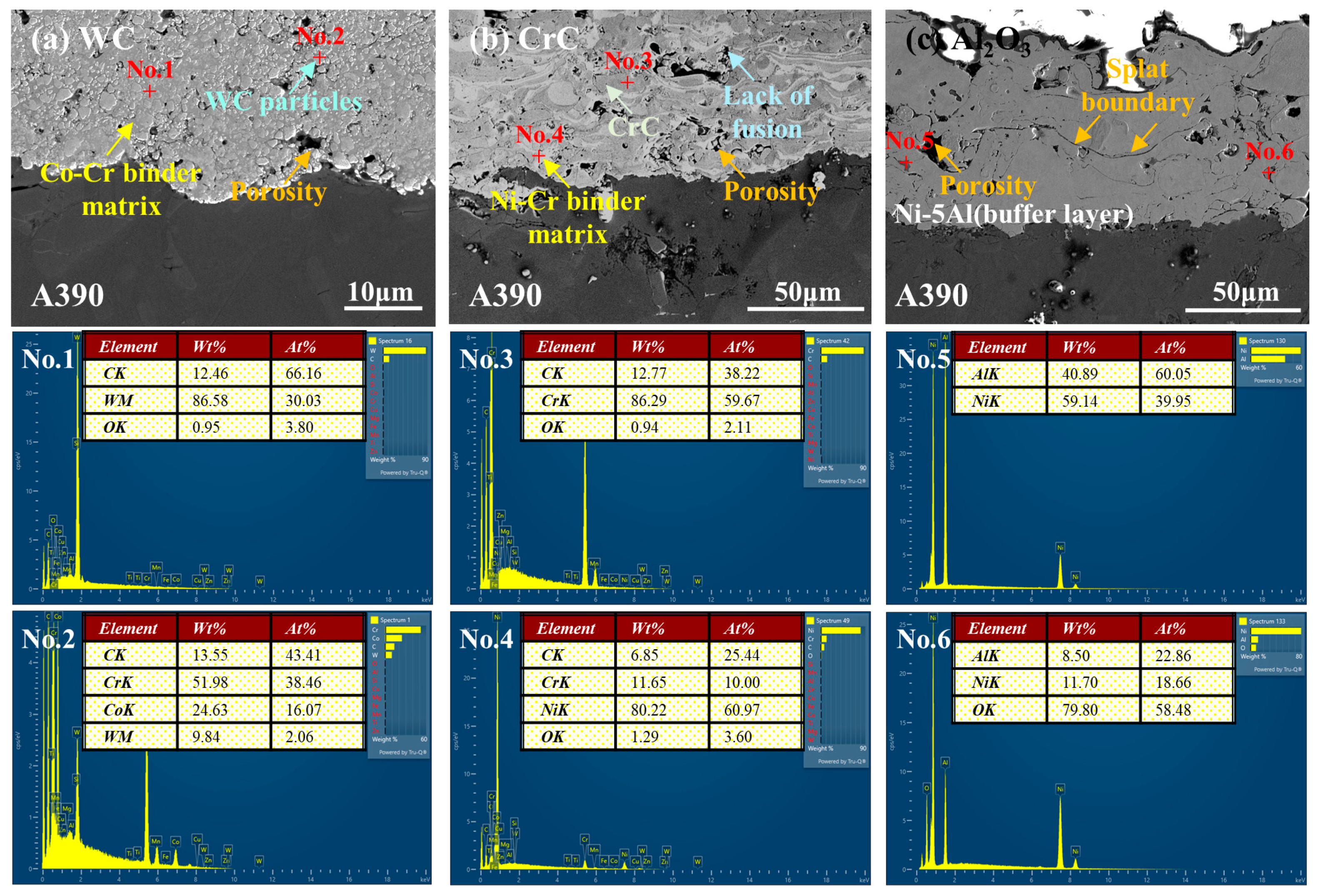
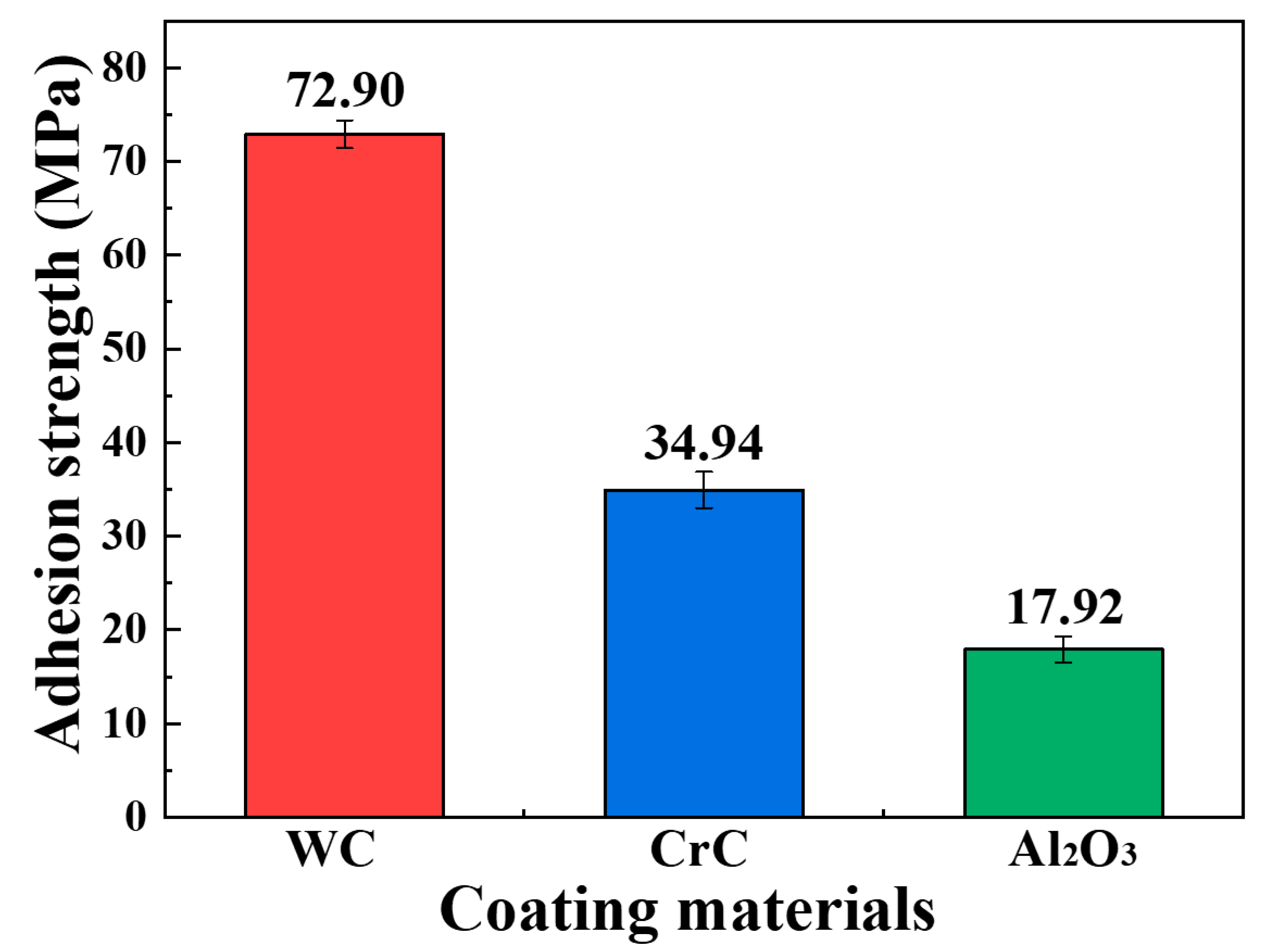
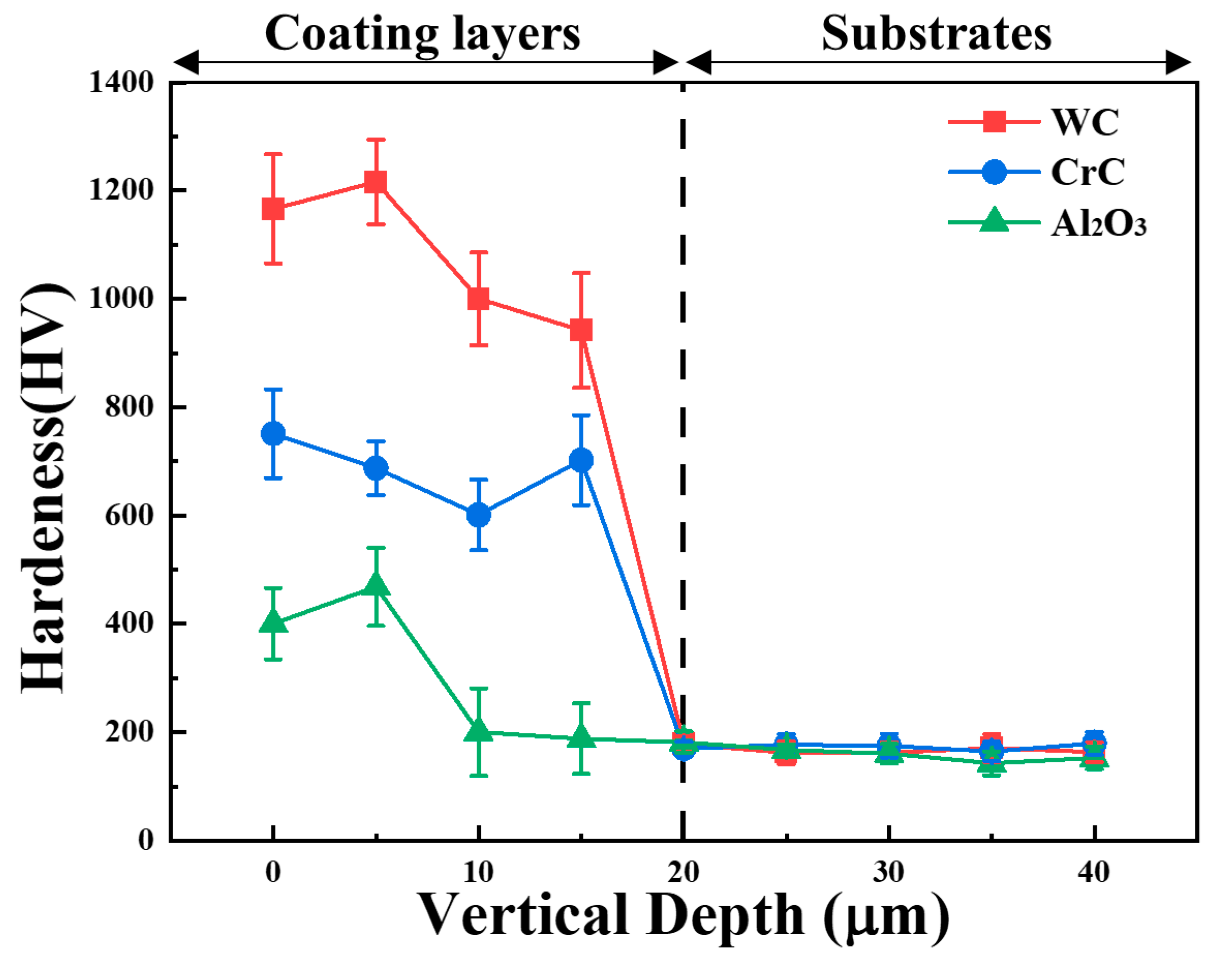
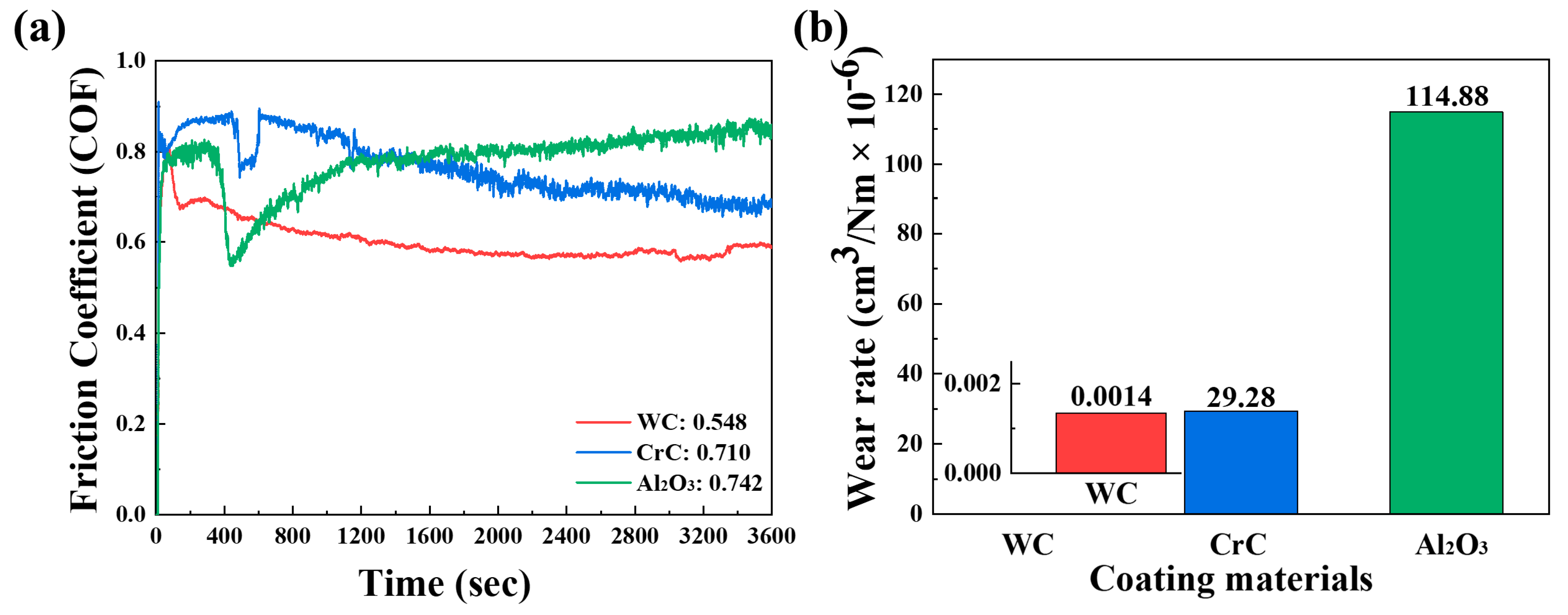
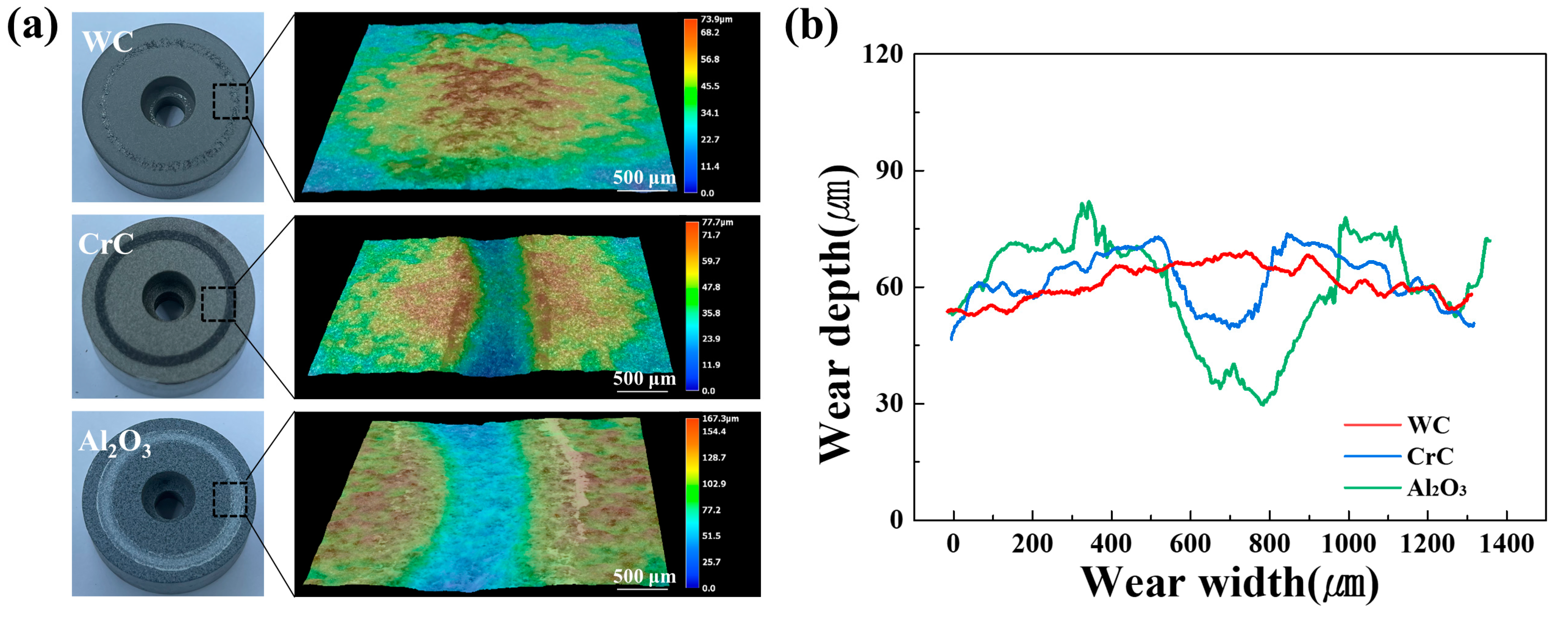
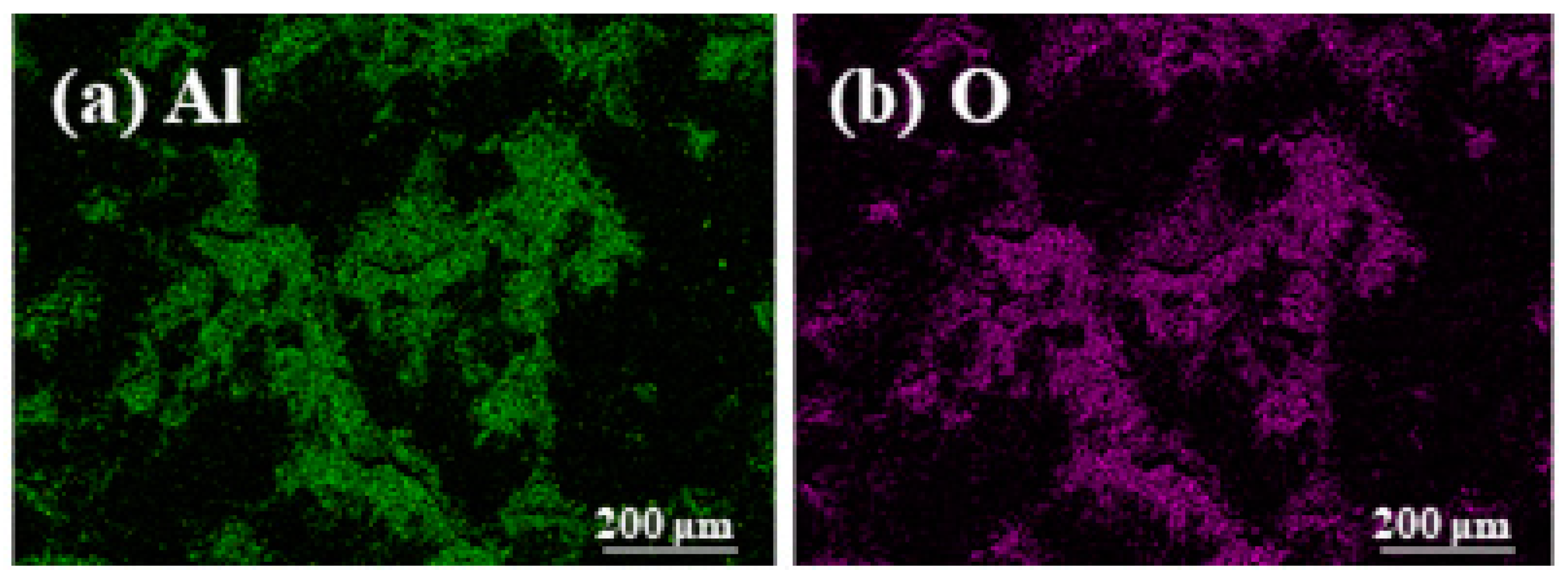
The aluminum alloy (A390) substrate was prepared by depositing all coating materials following a solution heat treatment at 525 °C for 4 h and subsequent aging at 190 °C for 6 h. The composition of the alloy was Si (17.0 wt.%), Cu (4.5 wt.%), Mg (0.55 wt.%), Fe (<0.5 wt.%), Ti (<0.2 wt.%), Mn (<0.1 wt.%), Zn (<0.1 wt.%), with the balance being Al.
The coating materials used in the experiment were 86WC–10Co–4Cr, 75Cr3C2–25NiCr, and Al2O3–3TiO2. The 86WC–10Co–4Cr material was deposited using the high velocity oxygen fuel (HVOF) process, while the 75Cr3C2–25NiCr and Al2O3-3TiO2 materials were deposited using the atmospheric plasma spray (APS) process. The variables for each coating process are listed in Table 1. For convenience, the materials will be referred to as WC, CrC, and Al2O3, respectively, throughout this paper. Prior to coating application, the substrate underwent cleaning and blasting for surface roughening. Subsequently, the Al2O3 material received a bond coating via a buffer layer of Ni–5Al to prevent delamination from the substrate, followed by thermal spraying. The WC and CrC materials were directly thermal sprayed without any bond coating. To ensure a uniform layer, the substrate was rotated during the thermal spraying process, maintaining a consistent thickness.
Specimens were cut and polished from #400 to #2400 grit, followed by polishing with 9, 6, 3, 1, and 0.04 μm diamond suspensions. Microstructural analyses of the cross-sections and surfaces of the coating layers were conducted using a field emission scanning electron microscope (FE-SEM; CLARA, Tescan, Brno, Czech Republic) and an energy dispersive spectrometer (EDS, EDAX, Pleasanton, CA, USA) with an acceleration voltage of 15.0 kV. The area fraction of cross-sectional defects was measured through image analysis. The adhesion strength between the substrate and coating layers was evaluated according to ASTM C633, with three tests conducted per specimen [22]. The upper cylinder and coating layer were fixed with adhesive, and a biaxial load was applied perpendicularly to the surface to determine the bonding strength. To assess the mechanical properties of each coating layer, a micro Vickers hardness test according to ASTM E384 [23] and a ball-on-disc test according to ASTM G99 [24] were performed. These tests were conducted using an HM-122 hardness test machine (Akashi Co., Tokyo, Japan) with a 0.1 kgf load applied for 10 s. Measurements were taken perpendicular to the coating layers and the substrate. Wear tests were conducted using a room-temperature abrasion tester (R&B, Daejeon, Republic of Korea) under the following conditions: load of 30 N, 100 RPM, 25 °C, and a radius of gyration of 11.5 mm, with Al2O3 as the counterpart material. Each test was repeated three times per sample, and the wear rate (cm3/N·m) was calculated from the weight loss after the tests using Equation (1):
W = V/(L × S)
where V is the wear loss volume (cm3) calculated from the cross-sectional area of the wear track, L is the load (N), and S is the sliding distance (m). Post-test wear track analysis was performed using FE-SEM and a high-resolution 3D microscope (VHX-7000, KEYENCE, Osaka, Japan) to analyze the wear mechanisms.

3. Results

Figure 1 shows the cross-sectional microstructure and EDS mapping results of the coating layers and substrates for different materials. In Figure 1a, the WC coating layer exhibits a uniformly distributed Co–Cr binder matrix (grey areas) with rounded WC particles (light grey areas), as revealed by quantitative EDS analysis. The coating layer displays very low porosity and high density due to the high impact velocity of the coating particles. The small WC particles within the coating layer were formed by the fracture of relatively faster and larger particles impacting the substrate during spraying [22]. The CrC coating in Figure 1b displays the typical lamellar structure of plasma-sprayed coatings, consisting of a Ni–Cr binder matrix (grey areas) and Cr carbide (light grey areas). It shows a lamellar structure parallel to the substrate, including porosity and splats. This lamellar structure is a characteristic microstructural feature of arc spray coatings, occurring when the coating material particles do not completely melt before application to the substrate or react with oxygen in the atmosphere to form oxides that mix with unmelted particles [22]. The Al2O3 coating in Figure 1c consists of the coating material and a Ni–5Al buffer layer that includes compounds formed between the coating material and NiAl metal, along with the substrate. The buffer layer shows splat boundaries, and microcracks were observed at the bonding interface with the substrate.
Based on the cross-sectional images, the interfacial cross-sectional defect (porosity and cracks) area fraction analysis using Image J software (https://imagej.net/ij/) showed defect area fractions of 0.101 for WC, 0.255 for CrC, and 0.351 for Al2O3. The WC coating layer exhibited relatively fewer interfacial defects compared to the other coating layers, which is expected to result in the highest bonding strength. This is followed by CrC and then Al2O3 in terms of expected bonding strength.
The actual bonding strength results between the substrate and coating materials are shown in Figure 2. The WC coating, which exhibited the fewest defects at the interface, demonstrated the highest bonding strength at 72.90 MPa. This was followed by CrC at 34.94 MPa and Al2O3 at 17.92 MPa. These results are consistent with the interfacial defect area fraction analysis. The lower bonding strengths of CrC and Al2O3 compared to WC are attributed to the presence of microcracks and splat boundaries in the coating layers and at the interface between the coating materials and the substrate. Lower bonding strength in a wear environment can lead to reduced durability of the coating, resulting in the separation of the coating layer from the substrate when subjected to forces exceeding the bonding strength. This, in turn, can compromise the protection of the substrate and cause deformation. Therefore, WC is deemed the most suitable coating material for protecting the A390 substrate.
Figure 3 shows the micro Vickers hardness values measured in the depth direction from the surface of the coating materials to the substrate. The average hardness values of the WC, CrC, and Al2O3 coating layers were 1081.39 HV, 685.40 HV, and 314.31 HV, respectively. The higher hardness value observed in the WC coating layer compared to other coating materials is attributed to the high-hardness tungsten carbide particles found in Figure 1. The Al2O3 coating layer exhibits an average micro hardness of 194.26 HV in the buffer layer, similar to the substrate. All coating materials were uniformly applied to a certain extent, overcoming the characteristic uneven thickness of thermal spray coatings, and no deformation of the substrate due to exposure to high temperatures during the process was observed.
Figure 4a,b show the wear rate based on the volume loss and the varying friction coefficient of the specimens after the wear test. The wear test results indicate that the wear rate follows the same order as the hardness results, with Al2O3, CrC, and WC showing decreasing wear rates, respectively. The variations in the friction coefficient graph are attributed to the increase (decrease) in the friction coefficient caused by wear debris (porosity). As shown in area fraction analysis, the WC material, which has fewer defects, exhibits uniform variations of microhardness. The average friction coefficients for the WC, CrC, and Al2O3 materials are 0.548, 0.710, and 0.742, respectively. The friction coefficients of the WC and CrC materials stabilize over time, indicating increasing friction resistance [25]. The CrC and Al2O3 materials exhibit rapid fluctuations compared to WC due to the significant number of cross-sectional defects, such as pores and cracks, which trap wear debris generated during the wear process and affect subsequent wear cycles. Notably, Al2O3 shows a continuously increasing variation in the friction coefficient.
Figure 5a,b show the 3D and 2D profiles of the wear track width and depth. The depth and width of the tracks increase in the order of WC, CrC, and Al2O3, correlating with the increase in wear loss rate. The 3D profile results in Figure 5a reveal that the surface of the CrC and Al2O3 coatings was indented by the counter material, whereas the WC surface appeared to be healed and convex. The analysis of the wear track depth (D) and width (W) using the 3D profiles in Figure 5b shows that the WC, CrC, and Al2O3 materials have wear track depths and widths of 7.7 µm (D) and 626.6 µm (W), 42.4 µm (D) and 2120.6 µm (W), and 24.0 µm (D) and 1472.1 µm (W), respectively. The WC material exhibits the least damaged wear track, suggesting it is the most effective coating layer for protecting the substrate.
To analyze the wear modes of each coating material, the microstructure of the wear track surface and EDS mapping results are shown in Figure 6 and Figure 7. Figure 6a–c, respectively, display the wear track surfaces of WC, CrC, and Al2O3. The wear marks on the protruded WC coating layer indicate adhesive wear behavior, where material from the counter face adheres to the coating layer. The microstructure shows evidence of abrasion and microcracks, and the EDS results in Figure 7 depict the presence of (a) Al and (b) O, which are components of the counter material. Typical features of abrasive wear, such as abrasion and microcracks, were observed. In the CrC coating, abrasion, microcracks, and craters were also identified, while the Al2O3 coating exhibited scuffing in the wear track due to the propagation of spalling pit cracks under repeated loading. The wear marks along the grooves in the Al2O3 and CrC wear tracks suggest the occurrence of adhesive wear in the coating layers. It is evident that both abrasive and adhesive wear modes occurred in all coating layers.

4. Conclusions

This study confirms that the WC coating is the most effective option for enhancing the wear resistance of the A390 aluminum alloy, providing superior adhesion strength, hardness, and wear resistance. While the CrC and Al2O3 coatings showed higher defect densities and wear rates, the WC coating’s dense microstructure and minimal defects contribute significantly to its robust performance. Overall, the findings underscore the WC coating’s potential to markedly enhance the durability of the A390 alloy in various industrial settings, offering a clear advantage over other tested coatings.

Author Contributions

Conceptualization, J.B. and E.L.; Methodology, J.B.; Software, J.B.; Validation, J.B.; Formal Analysis, J.B.; Investigation, J.B.; Resources, J.B. and E.L.; Data Curation, J.B.; Writing: Original Draft Preparation, J.B.; Writing: Review and Editing, J.B.; Visualization, J.B.; Supervision, E.L.; Project Administration, E.L.; Funding Acquisition, E.L. All authors have read and agreed to the published version of the manuscript.

Funding

This research was financially supported by the Institute of Civil Military Technology Cooperation funded by the Defense Acquisition Program Administration and Ministry of Trade, Industry and Energy of Korean government under grant No. UD10044TU.

Institutional Review Board Statement

Not applicable.

Informed Consent Statement

Not applicable.

Data Availability Statement

The data presented in this study are available on request from the corresponding author.

Conflicts of Interest

The authors declare no conflicts of interest.

References

  1. Bang, J.; Byon, E.; Lee, E. Effects of Na2B4O7·10H2O on microstructure and mechanical properties of AlSi7Mg0.3 and AlSi10MnMgAlSi10MnMg alloys. J. Adv. Mar. Eng. Technol. 2021, 45, 363–370. [Google Scholar] [CrossRef]
  2. Moon, G.; Seo, H.-I.; Seo, D.-H.; Lee, E. Application of the Convolutional Neural Network for Classification of the Aluminum Alloys Based on Their Microstructural Characteristics. JOM 2023, 75, 4858–4867. [Google Scholar] [CrossRef]
  3. Dash, S.S.; Chen, D. A Review on Processing–Microstructure–Property Relationships of Al-Si Alloys: Recent Advances in Deformation Behavior. Metals 2023, 13, 609. [Google Scholar] [CrossRef]
  4. Kang, H.-J.; Park, J.-Y.; Choi, Y.-S.; Cho, D.-H. Influence of the Solution and Artificial Aging Treatments on the Microstructure and Mechanical Properties of Die-Cast Al–Si–Mg Alloys. Metals 2022, 12, 71. [Google Scholar] [CrossRef]
  5. Bararpour, S.M.; Jamshidi Aval, H.; Jamaati, R.; Javidani, M. Effect of initial heat treatment of A390 alloy on microstructure and tribological behavior of friction surfaced coating. Surf. Coat. Technol. 2024, 478, 130359. [Google Scholar] [CrossRef]
  6. Lee, J.Y.; Lee, E. Crystallographic orientation-dependent corrosion behavior of aluminum under residual stress. Mater. Charact. 2023, 205, 113310. [Google Scholar] [CrossRef]
  7. Jonda, E.; Łatka, L.; Tomiczek, A.; Godzierz, M.; Pakieła, W.; Nuckowski, P. Microstructure Investigation of WC-Based Coatings Prepared by HVOF onto AZ31 Substrate. Materials 2022, 15, 40. [Google Scholar] [CrossRef]
  8. Trebuňová, M.; Kottfer, D.; Kyziol, K.; Kaňuchová, M.; Medveď, D.; Džunda, R.; Kianicová, M.; Rusinko, L.; Breznická, A.; Csatáryová, M. The WC and CrC Coatings Deposited from Carbonyls Using PE CVD Method—Structure and Properties. Materials 2023, 16, 5044. [Google Scholar] [CrossRef] [PubMed]
  9. Bang, J.; Kwon, H.; Byon, E.; Lee, E. Understanding of microstructures and mechanical properties of thermal sprayed Ni-based coatings with Al and Mo addition. J. Adv. Mar. Eng. Technol. 2022, 46, 342–347. [Google Scholar] [CrossRef]
  10. Amin, S.; Panchal, H. A review on thermal spray coating processes. Transfer 2016, 2, 556–563. [Google Scholar]
  11. Li, H.; Liu, P.; Huang, K.; Sun, R. Research and Application of High-Velocity Oxygen Fuel Coatings. Coatings 2022, 12, 828. [Google Scholar] [CrossRef]
  12. Turunen, E.; Suhonen, T.; Varis, T.; Hannula, S.-P. Optimization and Characterization of High Velocity Oxy-fuel Sprayed Coatings: Techniques, Materials, and Applications. Coatings 2011, 1, 17–52. [Google Scholar] [CrossRef]
  13. Goral, M.; Kubaszek, T.; Grabon, W.A.; Grochalski, K.; Drajewicz, M. The Concept of WC-CrC-Ni Plasma-Sprayed Coating with the Addition of YSZ Nanopowder for Cylinder Liner Applications. Materials 2023, 16, 1199. [Google Scholar] [CrossRef] [PubMed]
  14. Qin, J.; Chen, Y.; Liu, J.; Wang, Y. Revealing the role of sealing treatment on the electrochemical corrosion properties of HVOF-sprayed WC-20Cr3C2-7Ni/MWCNTs coating. J. Mater. Res. Technol. 2023, 25, 2486–2497. [Google Scholar] [CrossRef]
  15. Mauer, G.; Rauwald, K.-H.; Sohn, Y.J.; Vaßen, R. The Potential of High-Velocity Air-Fuel Spraying (HVAF) to Manufacture Bond Coats for Thermal Barrier Coating Systems. J. Therm. Spray Technol. 2024, 33, 746–755. [Google Scholar] [CrossRef]
  16. Rahman, M.; Ahmed, S.; Lee, K.; Kim, J. Surface preparation of aluminum by atmospheric-pressure plasma jet for suspension plasma sprayed ceramic coatings. Surf. Coat. Technol. 2024, 476, 130175. [Google Scholar] [CrossRef]
  17. Hu, J.; Zhang, C.; Wang, X.; Meng, X.; Dou, C.; Yu, H.; Wang, C.; Xue, J.; Qiao, Z.; Jiang, T. Improving the Wear Resistance Properties of 7A04 Aluminum Alloy with Three Surface Modification Coatings. Coatings 2024, 14, 476. [Google Scholar] [CrossRef]
  18. Hong, S.; Wang, Z.; Zhou, H.; Liu, X. Influences of sand concentration and flow velocity on hydro-abrasive erosion behaviors of HVOF sprayed Cr3C2-NiCr and WC-Cr3C2-Ni coatings. J. Mater. Res. Technol. 2022, 21, 1507–1518. [Google Scholar] [CrossRef]
  19. Pan, X.; Zhou, L.; Hu, D.; He, W.; Liu, P.; Yu, Z.; Liang, X. Superior wear resistance in cast aluminum alloy via femtosecond laser induced periodic surface structures and surface hardening layer. Appl. Surf. Sci 2023, 636, 157866. [Google Scholar] [CrossRef]
  20. Zhao, P.; Shi, Z.; Wang, X.; Li, Y.; Cao, Z.; Zhao, M.; Liang, J. A Review of the Laser Cladding of Metal-Based Alloys, Ceramic-Reinforced Composites, Amorphous Alloys, and High-Entropy Alloys on Aluminum Alloys. Lubricants 2023, 11, 482. [Google Scholar] [CrossRef]
  21. Rúa Ramirez, E.; Silvello, A.; Torres Diaz, E.; Vaz, R.F.; Garcia Cano, I. A Comparative Study of the Life Cycle Inventory of Thermally Sprayed WC-12Co Coatings. Metals 2014, 4, 431. [Google Scholar] [CrossRef]
  22. ASTM C633-13; Standard Test Method for Adhesion or Cohesion Strength of Thermal Spray Coatings. ASTM International: West Conshohocken, PA, USA, 2021.
  23. ASTM E384-22; Standard Test Method for Microindentation Hardness of Materials. ASTM International: West Conshohocken, PA, USA, 2022.
  24. ASTM G99-17; Standard Test Method for Wear Testing with a Pin-on-Disk Apparatus. ASTM International: West Conshohocken, PA, USA, 2023.
  25. Gao, P.-H.; Chen, B.-Y.; Wang, W.; Jia, H.; Li, J.-P.; Yang, Z.; Guo, Y.-C. Simultaneous increase of friction coefficient and wear resistance through HVOF sprayed WC-(nano WC-Co). Surf. Coat. Technol. 2019, 363, 379–389. [Google Scholar] [CrossRef]
Figure 1. Cross-sectional SEM images of the coatings on A390 substrate: (a) WC, (b) CrC, and (c) Al2O3 coatings, along with EDS qualitative analysis results of the points marked with red crosses.
Coatings 14 00853 g001
Figure 2. Adhesion strength between the substrate and the coating layers.
Coatings 14 00853 g002
Figure 3. Vertical distribution of micro Vickers hardness from the top surface of the coating layers to the substrate.
Coatings 14 00853 g003
Figure 4. (a) Friction coefficient and (b) wear rate of the coating layers.
Coatings 14 00853 g004
Figure 5. (a) 3D profiles and (b) 2D profiles showing the width and depth of the worn track on the coating layers.
Coatings 14 00853 g005
Figure 6. Wear track microstructures of WC, CrC, and Al2O3 analyzed by (a,c,e) 3D optical microscopy and (b,d,f) SEM.
Coatings 14 00853 g006
Figure 7. The element mapping of (a) Al and (b) O detected in Figure 6b.
Coatings 14 00853 g007
Table 1. Process parameters of spray coating.
Spray ParametersUnit
Coating materials86WC–10Co–4CrCr3C2–25NiCrAl2O3–3TiO2
Spray typeHVOFAPSAPS
Buffer layer-Ni–5Al-
Voltage36 V60 V60 V
Current600 mA600 mA600 mA
Air pressure40 psi105 psi105 psi
Spray Distance8 inch9 inch9 inch
Gun spraying angle909090
Gun/feed/spray rate (g/min)258080
Thickness150 μm150 μm100 μm
Buffer layer--Ni-5Al (50 μm)
Disclaimer/Publisher’s Note: The statements, opinions and data contained in all publications are solely those of the individual author(s) and contributor(s) and not of MDPI and/or the editor(s). MDPI and/or the editor(s) disclaim responsibility for any injury to people or property resulting from any ideas, methods, instructions or products referred to in the content.

