Article

Composite Paints with High Content of Metallic Microparticles for Electromagnetic Shielding Purposes

by
Romeo Cristian Ciobanu
1,*,
Mihaela Aradoaei
1,
Alina Ruxandra Caramitu
2,
Magdalena Valentina Lungu
2,
Oliver Daniel Schreiner
1 and
Ioana Ion
2
1
Department of Electrical Measurements and Materials, Gheorghe Asachi Technical University, 700050 Iasi, Romania
2
National Institute for Research and Development in Electrical Engineering ICPE–CA, 030138 Bucharest, Romania
*
Author to whom correspondence should be addressed.
Coatings 2024, 14(7), 874; https://doi.org/10.3390/coatings14070874
Submission received: 3 June 2024 / Revised: 22 June 2024 / Accepted: 1 July 2024 / Published: 12 July 2024

Abstract

:
This paper describes the technological process used to manufacture composite paints with a high content of metallic microparticles (Al and Fe) for automotive electromagnetic compatibility applications. The thickness of the deposited paint layer was larger for paints with a greater metal content, regardless of the plastic support used for paint deposition. The roughness of paint layers with a greater content of metal particles was about 30%–35% higher than that of layers with a lower metal particle content, regardless of the metal type. The surface roughness of paint layers containing Al was at least 2.5-times higher than that of paint layers containing Fe, an aspect that could be explained by the better formulation of the paint containing Fe. The dielectric loss and conductivity values crucially depend on the plastic substrate used, meaning that the dipolar polarization of the substrate enhances the effect of conductive paints. Based on the dielectric properties measured at 10 kHz, the optimal recipe for efficient electromagnetic compatibility was found to be 20 wt.% Fe powder, deposited on a sandblasted polycarbonate (PC) substrate. It is expected that formulations of paints with a high percentage of metallic particles will effectively compete with traditional plastic metallization technologies.

1. Introduction

Electrically conductive paint is typically made by integrating an electrically conductive pigment into a non-conductive resin binder. Applications for such paints include electromagnetic shielding, circuit prototyping and repair, protection against electrostatic discharge, and resistance to galvanic corrosion. The binder maintains the integrity of the paint and ensures adhesion to surfaces, while the conductive pigment creates a path for electrical flow. Metallic particles, such as copper, silver, and other malleable soft metals, are highly conductive and allow for the efficient transmission of the current in solvent-based liquid media. These particles are very fine to retain the wetting and adhesion properties characteristic of regular paints. Electrical charges move through the conductive fillers via short jumps between particles within the matrix. This mechanism is optimized when the fillers are highly concentrated and are in the shape of flakes or tubes. Spherical particles are less ideal for maximum conductivity but can provide a smooth finish and improved conductivity when used in combination with flakes. In addition to morphology, fillers differ significantly in terms of electrical conductivity, corrosion resistance, and cost.
Current technology and related conductive paint products on the market use various but limited pigments, including branched carbon powder, nickel flakes, silver-coated copper flakes, and/or silver flakes (e.g., [1,2,3,4,5,6,7,8]). Carbon, the most cost-effective filler material, is ideal for electromagnetic shielding and grounding applications. Silver, on the other hand, offers the highest level of conductivity and the greatest shielding efficiency, making it particularly useful in high-frequency electromagnetic shielding applications. Nickel- and silver-plated copper fillers are effective for electromagnetic shielding over a wider frequency range, with silver-plated copper excelling mainly at higher frequencies, although it does not have the same corrosion resistance as other pigments.
The trend in the development of new paints, mainly water-based paints, is to use particles under 1 μm (preferably nanoparticles) as additives, despite their higher cost. A common example is paint containing silver nanoparticles, which provides excellent antimicrobial properties against bacteria and human pathogens [9]. On the other hand, titanium dioxide (TiO2) nanoparticles (anatase type) are used in paints for their excellent UV protection properties [10]. The addition of silicon dioxide nanoparticles to paints can improve their macro- and micro-hardness, as well as their abrasion, scratch, and weather resistance. Adding silicon dioxide (SiO2) nanoparticles to polymeric resins creates paints with excellent abrasion properties; however, it decreases the elasticity of the paints, which is needed to resist the swelling and shrinking associated with temperature and humidity changes [5,6]. Finally, combining nanoparticles that have photocatalytic effects with those that have hydrophilic properties can result in paints with a self-cleaning effect [11]. Such characteristics can be very useful for paints used in electromagnetic shielding, but the association of certain non-conducting nanoparticles with metallic powders can diminish the electromagnetic properties of the paints. The dispersion of ceramic nanoparticles within the binder and their compatibility with metallic particles in conductive paint formulations can significantly influence the paint’s drying time, hardness, and reliability [12,13].
Bonding systems can vary considerably and influence the conductivity and shielding efficiency of the coatings, although not to the same extent as the choice of filler materials. However, they play a crucial role in determining the adhesion, durability, and chemical resistance of the coatings. Bonding systems, including solvent-based, water-based, epoxy, and urethane variants, also influence the method used for the coating application, determining properties such as the working time and the number of components/layers required [1,2,3,4,5,6,7,8]. Several examples of commercial conductive paints include the following: (1) Conductive acrylic paints: These coatings are easy to apply and fast-curing, as well as providing optimal electromagnetic shielding for plastic electronic enclosures; (2) Conductive epoxy paints: These paints offer superior levels of adhesion, durability, and chemical resistance, making them suitable for use in harsh environments; (3) Water-based conductive shielding paints: These paints are suitable for wood, walls, and other architectural applications; (4) Package-level protective coatings: These coatings are intended for short-range, high-frequency electromagnetic applications, with high-durability versions that resist wear and tear; (5) Electrostatic discharge-safe coatings: These durable coatings prevent electrostatic discharge on a wide variety of substrates; and (6) Conductive spray paints: These are conductive acrylic paints available in convenient aerosol cans. The current trend, mainly due to environmental concerns, is moving towards paints that use water-based systems [14].
Recent research has emphasized the use of composite powder fillers for conductive paints, such as graphite–silver [15], nickel–copper, carbon nanotubes (CNTs)–graphite [16], graphite and iron oxide [17,18], carbon-polymers [19,20], or MXene–graphene composites [21], etc. However, none of these have successfully outperformed existing paints on the market or passed routine tests to become marketable. On the other hand, paints intended for electromagnetic shielding are adapted according to the type of paint and surface. In general, they can be applied to most plastics, such as polypropylene (PP), polyvinylchloride (PVC), polycarbonate (PC), acrylonitrile butadiene styrene (ABS), bakelite, epoxy or polyurethane resins, and wood and glass treated with adhesion promoters.
The novelty of the presented research consists of the development of water-based composite paints containing metallic microparticles (Al and Fe). Despite their low price and relevant electrical properties, such particles have not been previously used in conductive paints. The originality of the developed formulations lies in their high content of metal (10 wt.% and 20 wt.%) and effective additives, enabling them to provide strong electromagnetic shielding and a high level of reliability on different plastic substrates, even with a single-layer application. Their potential applications are in electronic technology, particularly in the development of new autonomous electric vehicles that require stringent electromagnetic shielding to prevent interferences and protect sensitive sensors and Internet of Things (IoT) devices.

2. Materials and Methods

2.1. Preparation of Composite Paints with Metallic Microparticles

This research focused on water-based acrylic paints, known for the versatility of their applications, and offering advantages such as good water resistance, a wide range of color shades if needed, resistance to algae and mold growth, good vapor permeability, resistance to environmental factors, high film elasticity, excellent coverage, and the ease of their application (suitable for mechanical spraying, ideal for the electronic and automotive industries).
The basic formulation of the water-based acrylic paint consisted of a pigment (including metallic powder), a binder (resin), and solvent-water additives. The main characteristics of the spherical-shaped metallic powders (Al 800 nm and Fe 790 nm) are presented elsewhere [22]. The variance in the particle dimensions (larger for Fe particles) [22] benefits paint manufacturing because the larger distribution lowers the particle costs by approximately tenfold compared to narrower distributions and offers increased conductivity and superior shielding efficiency, as previously described.
Two types of composite paints, codified as V1 and V2, were developed with the following mass formulations:
V1—Solvent-water 42%; Polyoxyethylene (25) octyl phenyl ether-surfactant and buffer 2%; Butyl acrilate and Vinyl acetate-binder 44%; Dibutylphthalate-plasticizer 1%; Initiator, reducing agent, defoamer, preservative, and crosslinking polymer 1%, and metallic powder 10% with two variants, containing either Al or Fe powder.
V2—Solvent-water 37%; Polyoxyethylene (25) octyl phenyl ether–surfactant and buffer 2%; Butyl acrylate and Vinyl acetate-binder 39%; Dibutylphthalate-plasticizer 1%; Initiator, reducing agent, defoamer, preservative and crosslinking polymer 1%, and metallic powder 20% with two variants, containing either Al or Fe powder.
All ingredients used in the composite paint formulations comply with the European Union regulatory framework related to REACH (Registration, Evaluation, Authorization, and Restriction of Chemical Substances), ensuring that no “Substances of Very High Concern” (SVHCs) are present.
To homogenize the paints and prevent the agglomeration of the Al and Fe powders, ultrasonication was applied as follows: 30 min when mixing the metallic powders with the solvent, an additional 15 min when adding the binder and additives, and finally, 5 min before applying the paints to the support. The paint layers were spread on the surfaces of the glass or plastic substrate samples only after they had been cleaned of dust and debris with a dry cloth and degreased with acetone for glass, and with ethyl alcohol or a specific thinner for plastic substrate samples.

2.2. Substrate Materials for Paint Deposition

The substrate materials used for paint deposition were thermoplastics, specifically PC, PP, and PVC, with the following specifications:
PC S/N: polycarbonate plate, transparent, sandblasted, or natural/non-sandblasted (Guttagliss Hobbyglas type), cut into squares with sides of 30 mm.
PP: cylindrical PP pipe profile, cut into strips measuring 30 mm × 80 mm.
PVC: cylindrical PVC pipe profile, cut into strips measuring 30 mm × 80 mm.
The sandblasting process of the substrate materials was performed using an ECO PRESSURE 80-140 P Sandblasting Booth (Sablast Techn., Targu Mures, Romania) with the following specifications: maximum pressure: 10 bar, loading capacity: 350 Kg, abrasive grit: max. 1.5 mm; degree of sandblasting: SA-3.
Thirty samples were obtained from each type of material, Figure 1.

2.3. Deposition of Paints on Plastic Substrate Samples

When dispersing the paints on plastic substrate samples—regardless of the type of paint or substrate—an inhomogeneity of the surface was noticed, with paint agglomerations occurring when drying the layer, as presented in Figure 2 for PC S. The inhomogeneity and surface roughness seemed to be higher for paints containing Al particles.
A difference between paint deposition on glass and plastic substrate samples was noticeable, mainly due to the different contact angle of the water-based paints. It became evident that adding a tailored additive to the paint formulations was necessary to improve paint deposition on plastic substrates. Additionally, a slight pH change of the paints was tested. The pH was adjusted by adding 1 mL of 40% acetic acid per 100 g of paint and, separately, by adding 100 mg of 40% NaOH per 100 g of paint. In both cases, the paint precipitated, indicating that changing the pH was unnecessary. Finally, 0.05% hydrogen peroxide was introduced as an initiator and 0.05% sodium formaldehyde sulfoxylate (SFS) was added to reduce the potential chlorine content in water, in case further dilution of the paint was required by a third party.
The following additives were tested: sodium dodecyl sulfate (SDS) 1% and polyvinyl pyrrolidone (PVP) 1%. In both cases, better paint homogeneity was observed, making the paint easier to apply. The deposited film was glossy and uniform—especially when SDS was used as an additive—resulting in lower surface roughness, as shown in Figure 3 for V2 with Al on PC S.

2.4. Testing Equipment and Methods

Scanning electron microscopy (SEM) was performed using a Lyra III XMU system (TESCAN GROUP a.s., Brno-Kohoutovice, Czech Republic).
Ultrasonication of paint mixtures was conducted in a USC-300T-type VWR ultrasonic bath: capacity of 2.8 L, frequency of 45 kHz, tank sizes (width × depth × height): 237 mm × 134 mm × 100 mm (VWR International-Avantor Inc., Radnor, PA, USA).
Dielectric properties were determined using a broadband dielectric spectroscopy method with a 1260A dielectric spectrometer (Solartron Analytical, Farnborough, UK).
Differential Scanning Calorimetry (DSC) analysis was performed using a Setaram 131 Evo DSC instrument (Setaram, Caluire-et-Cuire, France), in non-isothermal mode (30–350 °C) with a heating rate of 10 °C/min, in an oxidizing atmosphere (synthetic air with a flow rate of 50 mL/min). The sample mass ranged from 2 mg to 4 mg.
The thickness of the paint layers (average of 3 measurements) was determined using a PosiTector® 200 tester (DeFelsko Corporation, Ogdensburg, NY, USA).
The surface topography of the samples was analyzed using a high-precision interferometric WYKO NT 1100 microscope (Veeco, Tucson, AZ, USA), with a resolution of up to 0.2 nm on the Oz axis. The derived parameters included: Ra—arithmetic average of the deviation values from the average profile on the scanned surface; Rq—root mean square roughness; and Rt—total roughness (difference between the highest and deepest points of the scanned surface). Roughness parameters were determined as the average of 3 measurements performed on the same sample in its central area, at a focal distance of 90 μm.

3. Results and Discussion

The technical specifications of the V1 and V2 paints applied with a brush on glass substrates are provided in Table 1 and Table 2.

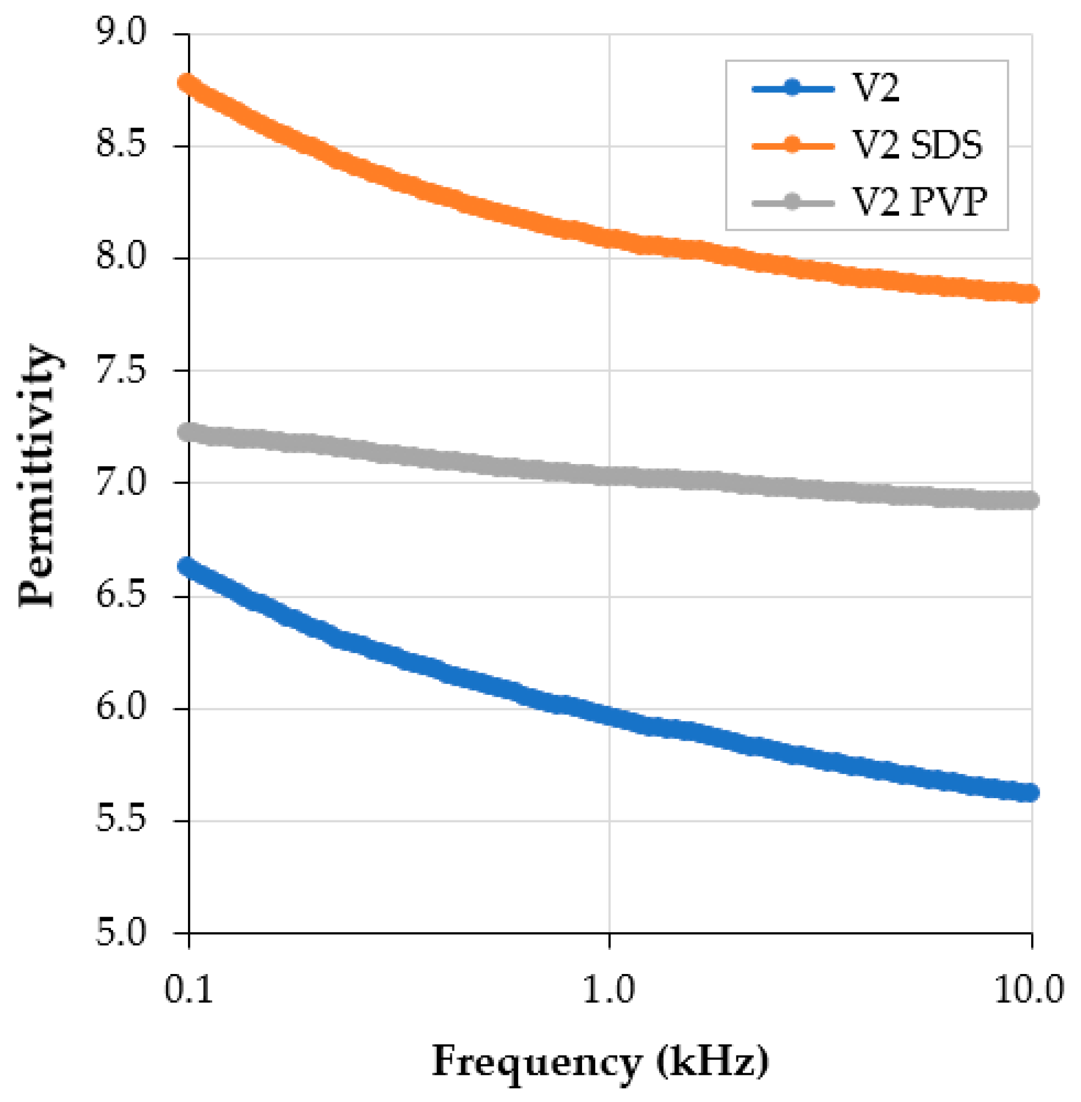
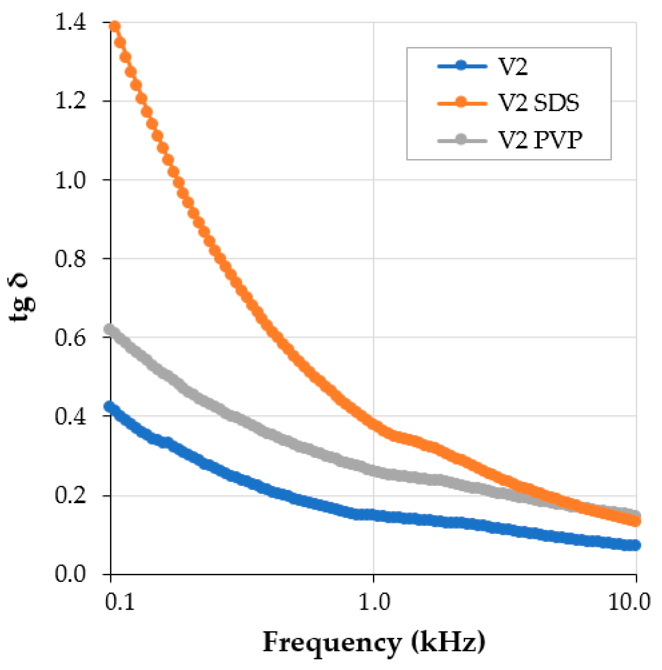
3.1. Dielectric Tests on Conductive Paints with Additives
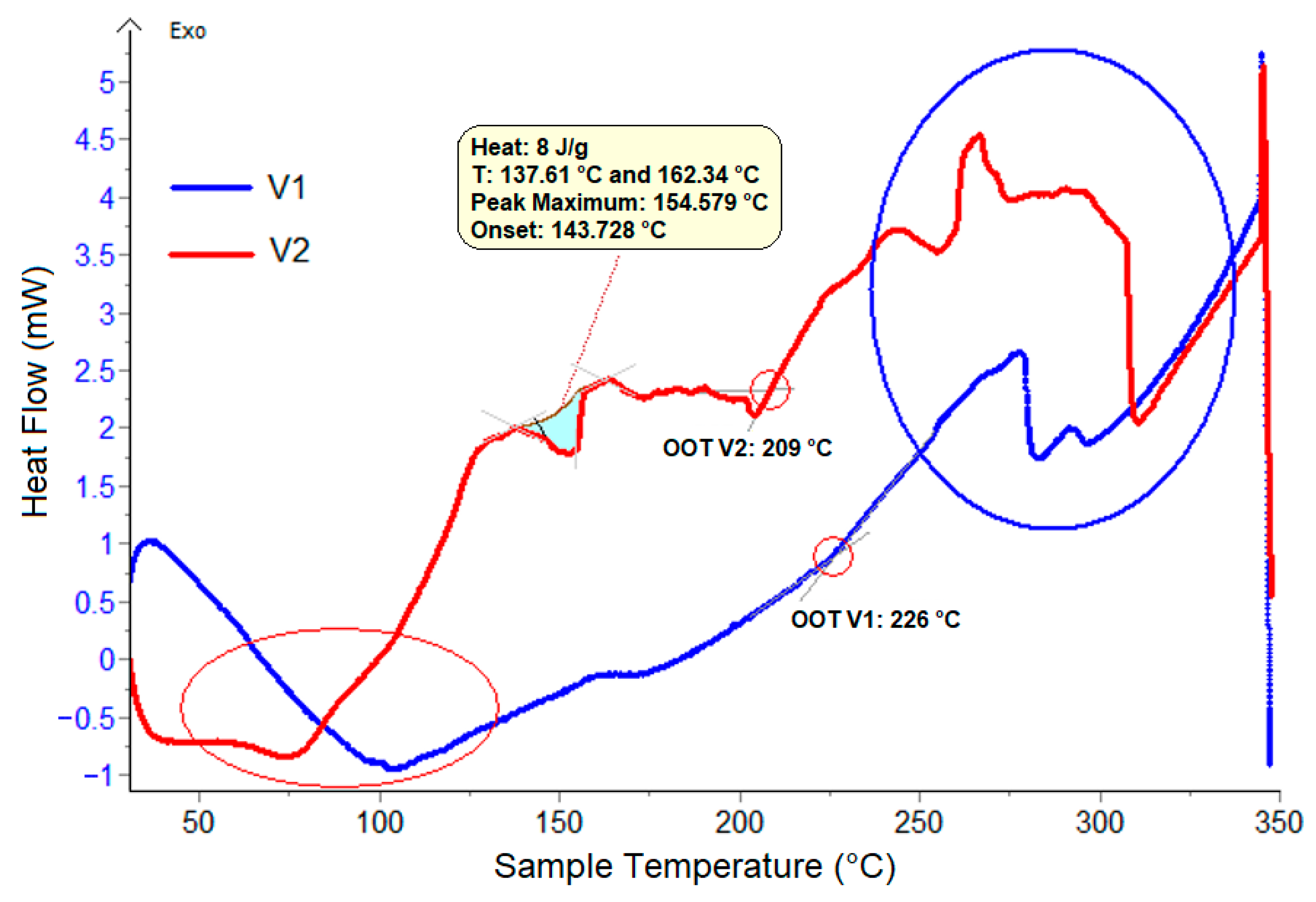
The tested parameters using broadband dielectric spectroscopy were the relative dielectric permittivity, dielectric loss factor (tg δ), and conductivity, as shown in Figure 4, Figure 5 and Figure 6, which illustrate the characteristics of the same V2 paint with Al on PC S. It was observed that the introduction of SDS and PVP additives slightly increased the dielectric parameters, with the most significant improvement being in dielectric permittivity. This improvement is attributed to the dipolar polarization of the SDS and PVP additives, as well as their effect on the interfacial polarization phenomenon at the contact between the binder and metallic particles. The permittivity characteristics slightly decreased with frequency, as shown in Figure 4.
Regarding the loss factor, it decreased with frequency in all cases, as illustrated in Figure 5. The interfacial polarization was also noted; at higher frequencies, the introduction of SDS and PVP additives showed a negligible effect. Concerning the conductivity, Figure 6, the effect of additives is evident—particularly at higher frequencies—indicating the potential use of such materials for electromagnetic shielding, especially in higher frequency ranges. The effect of additives is attributed to improving the compositional homogeneity of the paints and enhancing the affinity of the metallic particles to the binder. In all cases, the dielectric properties of the paints with the SDS additive were superior to those with the PVP additive. Consequently, SDS 1% was selected for introduction into all experimental paint formulations, to ensure the highest quality of the deposited films on plastic substrate samples and to achieve the best dielectric properties.
Maintaining the abbreviations as previously defined for the paints (including SDS addition) and the plastic substrates, the following expanded sample codes were used for further experiments and testing:
M1: PC N
M2: PC S
M3: PP
M4: PVC
M5: PC N with V1/Al
M6: PC S with V1/Al
M7: PC N with V2/Al
M8: PC S with V2/Al
M9: PC N with V1/Fe
M10: PC S with V1/Fe
M11: PC N with V2/Fe
M12: PC S with V2/Fe
M13: PP with V1/Al
M14: PVC with V1/Al
M15: PP with V2/Al
M16: PVC with V2/Al
M17: PP with V1/Fe
M18: PVC with V1/Fe
M19: PP with V2/Fe
M20: PVC with V2/Fe

3.2. DSC Analysis

Figure 7 presents the generic DSC thermograms recorded on samples of V1 and V2 with Fe powder, while the thermograms recorded on samples of V1 and V2 with Al powder show similar characteristics.
Depending on the observed thermal effects and their respective temperatures, DSC curves can be categorized into four main regions:
(i) 60–120 °C: This temperature range is specific for water evaporation. The DSC curves exhibited an endothermic peak in this region due to the evaporation of water from the paint composition. It is noted that the onset temperature of the evaporation process was lower for the V2 sample (approximately 60 °C) compared to the V1 sample (approximately 90 °C), a direct consequence of the metallic content, which facilitates energy accumulation. This phenomenon is similar to the common observation, seen during evaporation, of water being adsorbed onto the surface of certain metal particles—in this case, this was related to water near the Al or Fe particles. It was observed that the presence of an equal quantity of Al powder in the paint enhanced water evaporation compared to a similar quantity of Fe. This explains why the evaporation process started earlier in the paints containing Al powder.
(ii) 140–200 °C: In this temperature range, significant differences were observed in the DSC curves between the two types of paints. V2 exhibited a series of endothermic peaks, with the largest peak observed at approximately 155 °C. These peaks may have resulted from the evaporation of volatile compounds derived from the additives introduced into the paints, along with a pro-oxidative process that initiated in this temperature range. Once again, it was observed that a higher quantity of metallic microparticles, particularly in the case of Fe powder, enhanced this effect in the V2 paint.
(iii) 200–250 °C: During this temperature range, the oxidation process of the organic matrix within the paint occurred. According to the literature, materials with higher initial temperatures of oxidation processes tend to have greater stability [26]. It is evident that the V2 paint exhibited an Oxidation Onset Temperature (OOT) value of about 209 °C, significantly lower than that of the V1 paint, which exhibited an OOT of 226 °C. Therefore, the V2 paint demonstrated lower stability compared to the V1 paint, primarily due to the presence of a higher quantity of Fe powder that intensified the pro–oxidative action.
(iv) 250–350 °C: This temperature range is associated with the energetic thermo-oxidative decomposition of the remaining organic matters in paints. Both paints underwent this process in two stages, with the initiation temperature being significantly lower for the V2 paint (242 °C), compared to the V1 paint (309 °C). This confirms once again that the V2 paint exhibits lower stability than the V1 paint, and that a higher quantity of metal microparticles consistently enhances the thermo-oxidative processes, which readily initiated on the surface of metal particles.

3.3. Thickness of the Paint Layers

The thickness results summarized in Table 3 are the most relevant here, specifically the films deposited on sandblasted PC surfaces and on PP. Other results are consistent with these findings. It can be observed that the thickness was greater for the paints with a higher metal content (e.g., M8 vs. M6, or M12 vs. M10), and slightly greater for the paints containing Fe particles (M10 vs. M6, M12 vs. M8, or M19 vs. M15). However, regardless of the plastic substrate type used for paint deposition, the thickness of the paint layer remained relatively similar for the same paint type. For example, the average thickness was about 20 µm for the V1 paint and about 26 µm for the V2 paint, with minimal differences attributable to the types of metal particles present.

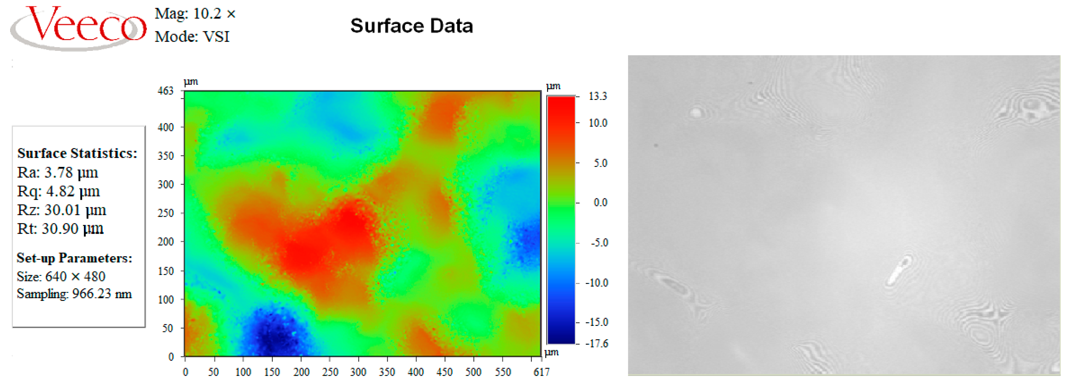
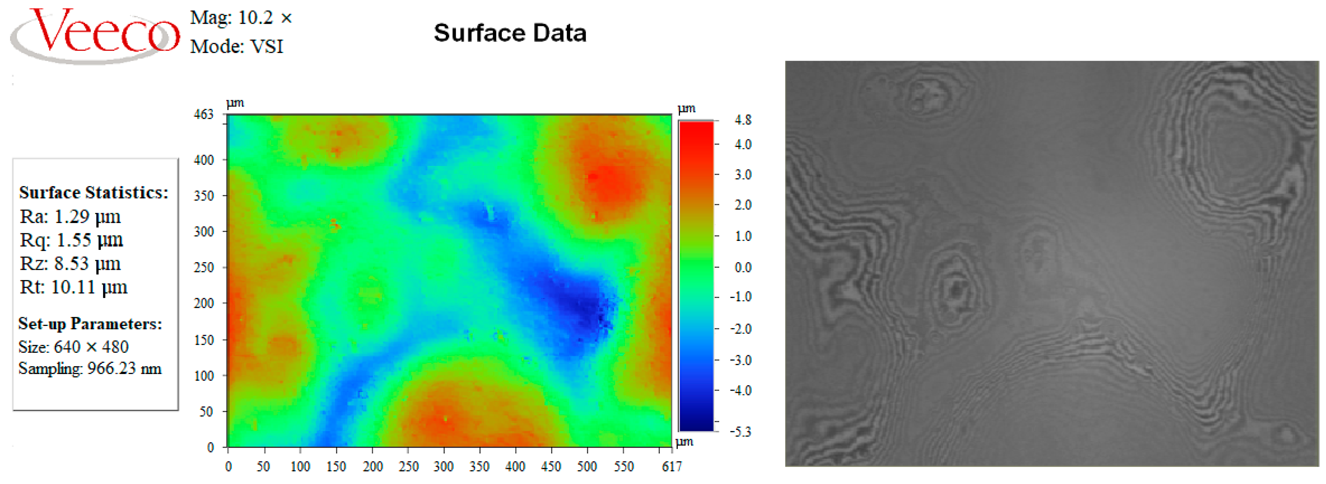
3.4. Surface Topography (Roughness)

The determination of the topography (roughness) of the sample surface was carried out according to ISO 10109:2014 [27]. The results are summarized in Figure 8, Figure 9, Figure 10 and Figure 11 and Table 4.
The surface roughness was higher for the layers from composite paints containing Al particles—an aspect already anticipated when the homologous paints without additives were analyzed, as mentioned above.
The data from Table 4 confirm the preliminary results: the roughness of the paint layers with a greater content of metal particles was about 30%–35% higher compared to the layers with a lower content of metal particle, regardless of the metal type. The roughness of the paint layers containing Al was at least 2.5 times higher compared to the paint layers containing Fe. This aspect could be explained by the better formulation of paints containing Fe in terms of the dispersibility of the metallic particles and/or affinity to the compatibilization additives. Another possible explanation could be the larger dispersion of Fe particle dimension, as presented in [22], which may ensure the better spatial deposition of a mixture of smaller and larger particles within the deposited layer, thus lowering the roughness of the paint. Regarding the influence of the plastic substrate, the lowest roughness was observed in the paint applied to PC, followed by PVC, and finally to PP, which presented the highest roughness regardless of the paint applied. It seems that the more-polar materials, in our case PC and PVC, offer better dispersion of the paint compared to PP.

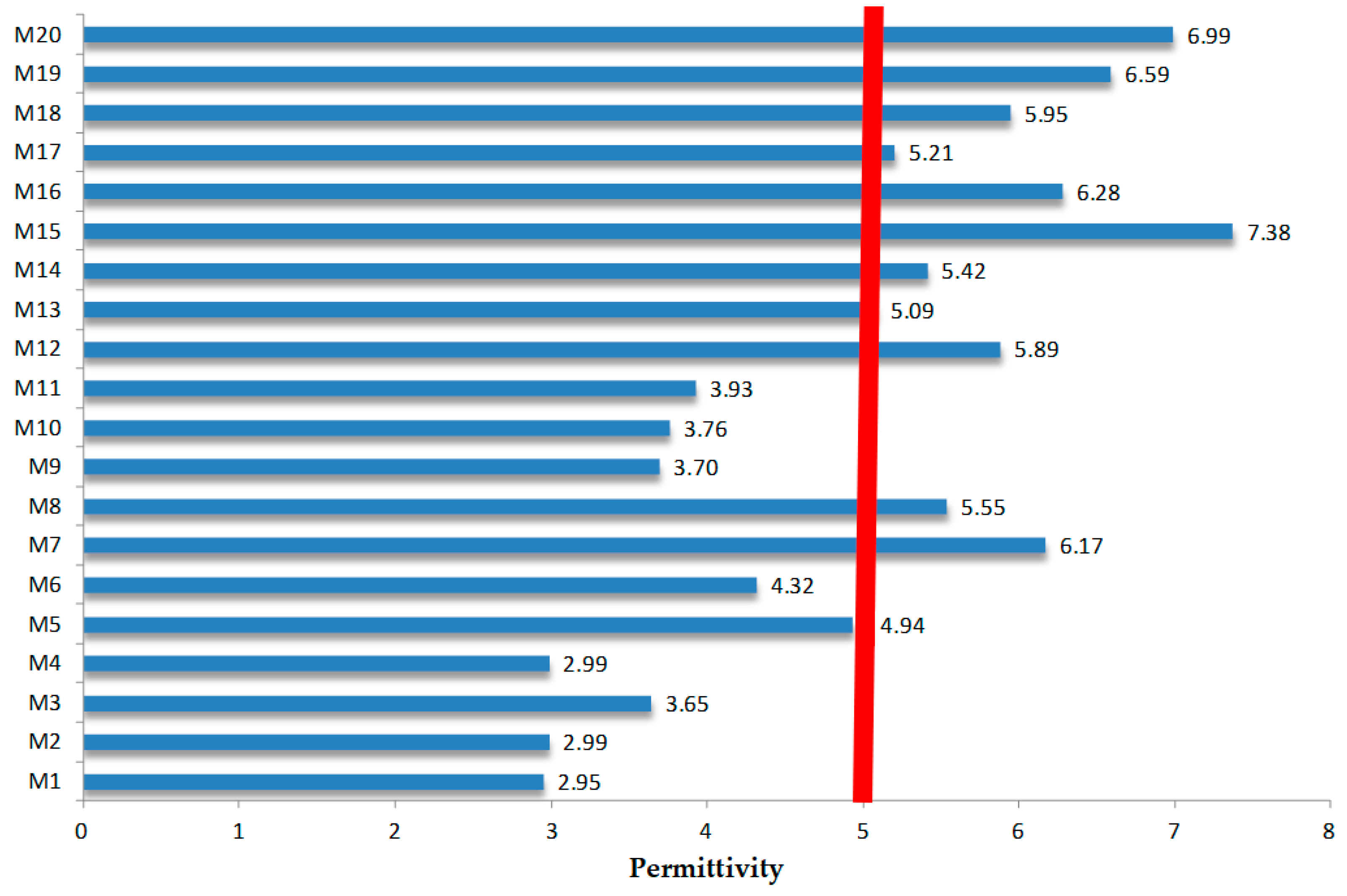
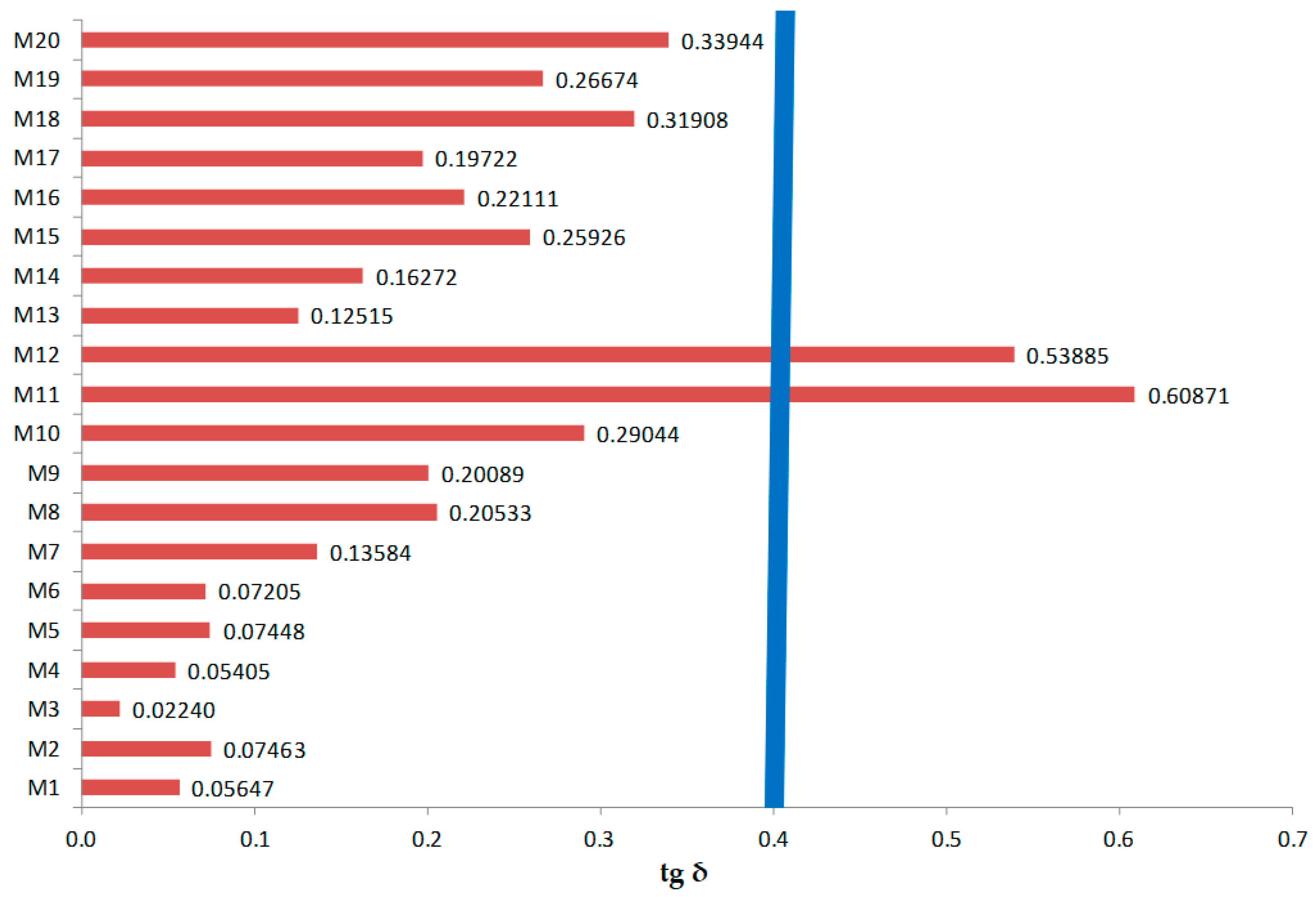
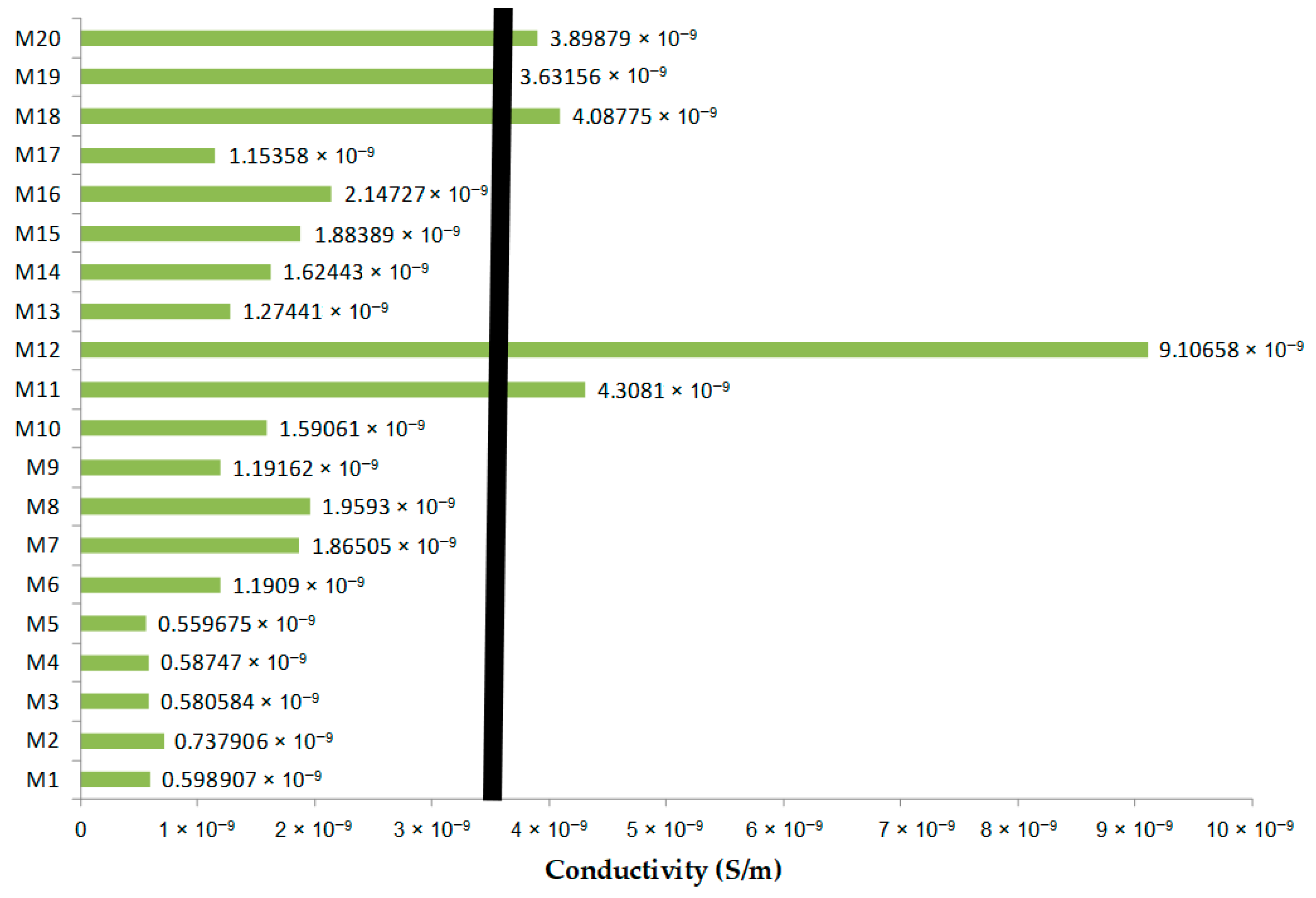
3.5. Comparative Analysis of Dielectric Parameters for M1–M20 Samples

Finally, the comparative evaluation of dielectric parameters for the M1–M20 samples was performed at 10 kHz, a reference frequency for electromagnetic compatibility analysis. The results for the dielectric permittivity, power loss angle (tg δ), and conductivity are presented in Figure 12, Figure 13 and Figure 14.
To better understand the dielectric behavior of a medium with a dielectric host and metallic inclusions, a simulation of the electromagnetic properties of such inhomogeneous materials was performed using CST Studio Suite software [28], partially based on the models presented in [29,30].
The main parameter defining the efficiency of an electromagnetic shielding material is related to its electromagnetic wave absorption—specifically, the value of the power loss density. The summary of the simulation results is presented in Figure 15 and Figure 16 as the power loss density for a simulated paint with a 10% mass ratio (MR) of metallic powder, with an average particle size of 1 μm (equivalent to V1).
The power loss density of the composite paints with Fe powder was at least twice as high compared to the paints with Al powder, due to the additional magnetic properties of the Fe powder. This specific phenomenon of energy absorption explains why paints with Fe show increased values of the dielectric loss factor compared to those with Al. Additionally, a higher percentage of metal powder in the paint leads to higher values of dielectric loss (tg δ). It was clear from the beginning that the paints containing Fe powder offered superior electromagnetic shielding effects compared to the paints with Al powder.
Regarding the dielectric permittivity of the paints, it was slightly higher for the samples containing Al particles due to the higher conductivity of Al compared to Fe. The values were also larger when the paint formulation included a higher percentage of metal powder, for both metals. The conductivity followed the same trend observed for the other dielectric parameters of the paints.
What was notably observed was the impact of the plastic substrate type on the dielectric parameters of the paint layers. This aspect is also relevant when designing electronic equipment housings for automotive applications to maximize the electromagnetic shielding effect of the applied paints. In our case, the dielectric parameters, mainly the permittivity and dielectric loss factor, essentially depended on the plastic substrate on which the paints were applied—being significantly higher for PC, especially if sandblasted, followed by PVC, for all types of deposited paints. This phenomenon can be explained by a synergetic effect of the dipolar polarization of the plastic substrate, which enhanced the effect of conductive paints when comparing PC and PVC with PP. When comparing the original and sandblasted PC, the superior performance of the sandblasted substrate can be explained by a better adherence of the paint to the substrate, which additionally induced interfacial polarization effects.
To determine the optimal formulation for efficient electromagnetic compatibility under the described conditions, minimal limit values for the dielectric parameters had to be established. Examples of such limit values for the dielectric parameters are shown in Figure 12, Figure 13 and Figure 14 as vertical bars, e.g., 5 for relative dielectric permittivity, 0.4 for the dielectric loss factor (tg δ), and 3.5 × 10⁻⁹ S/m for conductivity. Accordingly, the formulation involving V2 paint with Fe powder applied on sandblasted PC appeared to offer the best characteristics, confirming the accuracy of the electromagnetic simulation. It is evident that for different operating conditions, the measurements presented in Section 3.5 must be repeated at the specific frequency required for the intended use. Additionally, the substrate material and configuration must be considered, adhering to standards for automotive electromagnetic compatibility [31], for which the presented conductive paints are intended.
In the literature, studies on electromagnetic shielding paints with metallic particles are very limited, excepting the commercial formulations mentioned in [1,2,3,4,5,6,7,8]. These formulations vary in recipe and types and concentrations of conductive particles, making direct comparison with our study impractical. On the other hand, the only patent related to a paint with a high content of metallic powder for electromagnetic shielding is [32], which includes 20% metallic flakes of either Au, Ni, or Cu, ranging from 20–100 μm in length and 1–3 μm in thickness. However, the patent does not specify how these flakes are manufactured. The single-layer coating thickness of the paint is stated to be 57 μm, but details regarding the dispersion process of the paint and the substrate on which the paint is applied are absent. Essentially, the patent describes a fluid medium with metallic flakes that can stack and form multilayers after drying, resembling a pseudo-metallization process rather than a conventional paint. From this perspective, the paints described in our paper offer clear advantages compared to those described in the patent [32], both in terms of manufacturing and dispersing technology, and in the characteristics of the coatings for the electromagnetic shielding applications.
It is important to emphasize that the use of conductive paints for electromagnetic shielding is currently limited due to the restricted types and quantities of conducting particles present in existing conductive paint formulations. Developing paints with a high content of metallic powders for electromagnetic shielding remains a persistent challenge. At present, the direct metallization of plastic enclosures appears to offer superior characteristics and is preferred, despite its higher cost and technological challenges (e.g., using metallization baths) [33,34,35]. However, it is expected that the paint formulations described above, with a high percentage of metallic particles, will effectively address this challenge. These conductive paints could potentially compete successfully with current plastic metallization technologies, especially since mechanical application by spraying is a common procedure in the automotive industry.
Regarding the environmental challenges in developing water-based paints with electromagnetic properties, it is important to note that water-based paints emit fewer volatile organic compounds (VOCs) into the air compared to traditional paints containing volatile chemical solvents. This reduces the risk of air pollution and associated health problems. Water-based paints are also less likely to contaminate water sources, thus lowering the risk of water pollution. Additionally, water-based paints are generally unregulated due to their non-flammability, non-toxicity, and overall safety during use. However, paints containing metallic pigments are regulated as hazardous waste when disposed, necessitating additional recycling strategies.
According to Verified Market Research [36], the global water-based coatings market size was valued at USD 68.65 billion in 2023 and is projected to reach USD 99.16 billion by 2030, growing at a Compound Annual Growth Rate (CAGR) of 5.21% during the forecast period from 2024 to 2030. This growth is driven by the increasing emphasis on sustainability and advancements in resin, additive, and pigment technologies. On the other hand, the market for electromagnetic shielding materials is expected to expand due to growing demand in consumer electronics, with a market size valued at USD 7.31 billion in 2023. It is projected to grow from USD 7.74 billion in 2024 to USD 11.56 billion by 2032, exhibiting a CAGR of 5.14% during the forecast period from 2024 to 2032 [37]. Consequently, considering the maturity of water-based paint technologies and the demand for new shielding solutions, paints with a high content of metallic powders may represent a significant step forward, offering sustainable technology in an emerging market.

4. Conclusions

The paper describes a technological process to manufacture composite water-based acrylic paints with high contents (10 wt.% and 20 wt.%) of metallic microparticles (Al 800 nm and Fe 790 nm) for automotive electromagnetic compatibility applications. To achieve a better homogeneity of the paint layer and a glossy, uniform film that is easier to apply on thermoplastic substrates, sodium dodecyl sulfate (SDS) in a content of 1 wt.% was identified as the optimal additive solution.
The DSC analysis emphasized that composite water-based paints with higher contents of metallic particles exhibited significantly lower stability, attributed to increased pro-oxidative activity at the metallic particle level. The thickness of the deposited paint layer was greater for the paints with a higher metal content, regardless of the plastic substrate used for paint deposition.
The surface roughness of the paint layers with a greater content of metal particles was about 30%–35% higher compared to the layers with a lower metal particle content, regardless of the metal type. The roughness of the paint layers containing Al was at least 2.5-times higher than that of the paint layers containing Fe, which may be attributed to the superior formulation of paints containing Fe.
The dielectric loss and conductivity values were significantly influenced by the type of plastic substrate, with higher values observed for PC—especially when sandblasted—followed by PVC. This indicates that the dipolar polarization of the plastic substrate plays an essential role and enhances the effect of conductive paints. Additionally, a higher percentage of metal powder in the paint leads to higher values. Based on the dielectric properties measured at 10 kHz, the optimal formulation for efficient electromagnetic compatibility was determined to be the recipe with 20 wt.% Fe powder, deposited on sandblasted PC substrate.
It is expected that the formulations of composite water-based paints with a high percentage of metallic particles will effectively compete with traditional plastic metallization technologies, particularly in the automotive industry, where mechanical application via spraying is a common practice.

Author Contributions

Conceptualization, R.C.C. and A.R.C.; methodology, R.C.C., M.A. and A.R.C.; validation, R.C.C. and M.A.; formal analysis, M.V.L., O.D.S. and M.A.; investigation, R.C.C., O.D.S., I.I., M.V.L., M.A. and A.R.C.; data curation, R.C.C., M.A., I.I. and O.D.S.; writing—original draft preparation, R.C.C.; writing—review and editing, R.C.C., A.R.C. and M.V.L.; visualization, R.C.C. and A.R.C.; supervision, and R.C.C. All authors have read and agreed to the published version of the manuscript.

Funding

The research received no external funding.

Institutional Review Board Statement

Not applicable.

Informed Consent Statement

Not applicable.

Data Availability Statement

Data are contained within the article.

Acknowledgments

The research presented in this paper represents a partial dissemination of the results achieved within the grant: Nanostructured paints and primers with electromagnetic shielding properties, with impact in the field of automotive components, 298/30.06.2020, SMIS 120155.

Conflicts of Interest

The authors declare no conflicts of interest.

References

  1. EMC Electrically Conductive Paints. Available online: https://www.solianiemc.com/en/cp/emc-electrically-conductive-paints/?gad_source=1&gclid=Cj0KCQjwjLGyBhCYARIsAPqTz1-DOF1Sw7J8wFzhbDIZLBd4b8Z5UxsiopHr2oeQ_mM4k1MuQkk-btgaAsFvEALw_wcB (accessed on 30 May 2024).
  2. EMF and RFI Shielding with Conductive Paints. Available online: https://www.antala.uk/emf-and-rfi-shielding-with-conductive-paints/ (accessed on 30 May 2024).
  3. Conductive Paints and Coatings. Available online: https://limitless-shielding.com/conductive-paints-and-coatings/ (accessed on 30 May 2024).
  4. ECOS Paints. Available online: https://ecospaints.net/blog/what-to-know-about-electromagnetic-shielding-materials (accessed on 30 May 2024).
  5. Conductive Translucent Paint. Available online: https://hollandshielding.com/en/conductive-translucent-paint?gad_source=1&gclid=CjwKCAjw9cCyBhBzEiwAJTUWNZC2A5l8HgsLs4KaJrIJbPz6e8rSoxmem-6Wv9nuq7kMi8Koz6ZhDhoCCHAQAvD_BwE (accessed on 30 May 2024).
  6. Conductive Paints. Available online: https://mgchemicals.com/category/conductive-paint/ (accessed on 30 May 2024).
  7. Electric Paint. Available online: https://www.bareconductive.com/collections/electric-paint (accessed on 30 May 2024).
  8. Electrically Conductive Paints. Available online: https://www.euro-technologies.eu/en/product/electrically-conductive-paints/ (accessed on 30 May 2024).
  9. Künniger, T.; Heeb, M.; Arnold, M. Antimicrobial efficacy of silver nanoparticles in transparent wood coatings. Eur. J. Wood Wood Prod. 2014, 72, 285–288. [Google Scholar] [CrossRef]
  10. Marolt, T.; Sever Škapin, A.; Bernard, J.; Živec, P.; Gaberšček, M. Photocatalytic activity of anatase-containing facade coatings. Surf. Coat. Technol. 2011, 206, 1355–1361. [Google Scholar] [CrossRef]
  11. Solano, R.; Patino-Ruiz, D.; Herrera, A. Preparation of modified paints with nano-structured additives and its potential applications. Nanomater. Nanotechnol. 2020, 10, 1847980420909188. [Google Scholar] [CrossRef]
  12. Héritier, P.A. The Impact of Particulate Matters and Nanoparticles on Thermoplastic Polymer Coatings and Paint Layers. Polymers 2022, 14, 2477. [Google Scholar] [CrossRef] [PubMed]
  13. González-Barriuso, M.; Soriano, L. Conductive paints development through nanotechnology. Prog. Org. Coat. 2016, 95, 85–90. [Google Scholar]
  14. Tudose, I.V.; Mouratis, K.; Ionescu, O.N.; Romanitan, C.; Pachiu, C.; Popescu, M.; Khomenko, V.; Butenko, O.; Chernysh, O.; Kenanakis, G.; et al. Novel Water-Based Paints for Composite Materials Used in Electromagnetic Shielding Applications. Nanomaterials 2022, 12, 487. [Google Scholar] [CrossRef] [PubMed]
  15. Tudose, I.V.; Mouratis, K.; Ionescu, O.N.; Romanitan, C.; Pachiu, C.; Pricop, E.; Khomenko, V.H.; Butenko, O.; Chernysh, O.; Barsukov, V.Z.; et al. Carbon Allotropes-Based Paints and Their Composite Coatings for Electromagnetic Shielding Applications. Nanomaterials 2022, 12, 1839. [Google Scholar] [CrossRef] [PubMed]
  16. Barsukov, V.; Senyk; Kuryptia, Y.; Butenko, O.; Chernysh, O.; Khomenko, V.; Suchea, M.; Koudoumas, E. Composite paints for electromagnetic shielding. AIP Conf. Proc. 2023, 2803, 020001. [Google Scholar] [CrossRef]
  17. Khomenko, V.; Butenko, O.; Chernysh, O.; Barsukov, V.; Suchea, M.P.; Koudoumas, E. Electromagnetic Shielding of Composite Films Based on Graphite, Graphitized Carbon Black and Iron-Oxide. Coatings 2022, 12, 665. [Google Scholar] [CrossRef]
  18. Demirci, G.; Okuyucu, S.; Hoda, N.; Topel, Ö. Assessment of Electromagnetic Shielding Efficacy of Magnetic Metal Oxide Nanoparticles and their Application in Electromagnetic Shielding Paints. Chem. Eur. 2024, 9, e202304078. [Google Scholar] [CrossRef]
  19. Barsukov, V.; Senyk, I.; Kryukova, O.; Butenko, O. Composite Carbon-Polymer Materials for Electromagnetic Radiation Shielding. Mater. Today Proc. 2018, 5, 15909–15914. [Google Scholar] [CrossRef]
  20. Folgueras, L.; Alves, M.; Rezende, M.C. Electromagnetic Radiation Absorbing Paints Based on Carbonyl Iron and Polyaniline. In Proceedings of the 2009 SBMO/IEEE MTT-S International Microwave and Optoelectronics Conference (IMOC), Belem, Brazil, 3–6 November 2009. [Google Scholar] [CrossRef]
  21. Graphene Based Paint-Like Composites for Electromagnetic Shielding in the GHz Frequency Range. Available online: https://www.phantomsnet.net/Graphene_Conf/2014/Abstracts/[email protected]_graphene%20based%20layers%20for%20electromagnetic%20shielding.pdf (accessed on 30 May 2024).
  22. Kim, Y.; Lee, B.W. A Study on MXene/Graphene Composite Coatings for Electromagnetic Shielding Paints. Meet. Abstr. 2023, MA2023-02, 1042. [Google Scholar] [CrossRef]
  23. Paints and Varnishes. Determination of Density. Part 4: Cylinder Method under Pressure: SR EN ISO 2811-2002. Available online: https://magazin.asro.ro/ro/standard/191719 (accessed on 30 May 2024).
  24. SR ISO 6504-3:2003; Paints and Varnishes. Determination of Coverage Power. ISO: Geneva, Switzerland, 2003. Available online: https://magazin.asro.ro/ro/standard/77636 (accessed on 30 May 2024).
  25. BS EN 29117:1992; Paints and Varnishes. Determination of Through-Dry State and Through-Dry Time. ISO: Geneva, Switzerland, 1992. Available online: https://standards.iteh.ai/catalog/standards/cen/5972906c-2cb8-4c79-8484-ad3b4903d282/en-29117-1992 (accessed on 30 May 2024).
  26. ASTM E2009-08(2014)e1; Standard Test Methods for Oxidation Onset Temperature of Hydro-Carbons by Differential Scanning Calorimetry. ASTM: West Conshohocken, PA, USA, 2014. Available online: https://www.astm.org/e2009-08r14e01.html (accessed on 30 May 2024).
  27. Optics and Optical Instruments: ISO 10109:2014, Revised in 2024 for Environmental Testing. Available online: https://www.iso.org/standard/82186.html (accessed on 30 May 2024).
  28. CST Studio Suite Software. Available online: https://www.3ds.com/products/simulia/electromagnetic-simulation (accessed on 20 June 2024).
  29. Duan, Z.; Linton, D.; Scanlon, W. Investigating the Permittivity of Three-Dimensional Metal Particles Embedded in a Dielectric Medium with Random Distributions. In Proceedings of the 2nd International Congress on Advanced Electromagnetic Materials in Microwaves and Optics, Pamplona, Spain, 21–26 September 2008; pp. 217–219. [Google Scholar]
  30. Ghodgaonkar, D.K.; Varadan, V.V.; Varadan, V.K. Free-Space Measurement of Complex Permittivity and Complex Permeability of Magnetic Materials at Microwave Frequencies. IEEE Trans. Instrum. Meas. 1990, 39, 387–394. [Google Scholar] [CrossRef]
  31. Automotive Electromagnetic Compatibility (EMC) Test Standards. Available online: https://learnemc.com/automotive-emc-test-standards (accessed on 30 May 2024).
  32. Patent WO 2009/095654 A1. Available online: https://patentimages.storage.googleapis.com/0a/3e/61/befbb893b347a6/WO2009095654A1.pdf (accessed on 20 June 2024).
  33. Plastic Metallization. Available online: https://www.teprosa.de/en/metallization/ (accessed on 30 May 2024).
  34. Metallization of Plastics. Available online: https://www.cybershieldinc.com/wp-content/uploads/2013/05/Cybershield-Metallization-of-Plastics.pdf (accessed on 30 May 2024).
  35. Metallization Solutions. Available online: https://impactcoatings.com/metallization/ (accessed on 30 May 2024).
  36. The Rise of Water-Based Coatings. Available online: https://www.pcimag.com/articles/112266-the-rise-of-water-based-coatings (accessed on 20 June 2024).
  37. Global EMI & RFI Shielding Materials Market Overview. Available online: https://www.marketresearchfuture.com/reports/emi-rfi-shielding-materials-market-7687?utm_term=&utm_campaign=&utm_source=adwords&utm_medium=ppc&hsa_acc=2893753364&hsa_cam=20373674291&hsa_grp=150985931723&hsa_ad=665909881832&hsa_src=g&hsa_tgt=dsa-2089395925824&hsa_kw=&hsa_mt=&hsa_net=adwords&hsa_ver=3&gad_source=1 (accessed on 20 June 2024).
Figure 1. Substrate samples of (a) PC N, (b) PC S, and (c) PP and PVC used for paint deposition.
Coatings 14 00874 g001
Figure 2. Paint deposition, with inhomogeneity of the surface—V2 with Fe (a) and Al (b).
Coatings 14 00874 g002
Figure 3. Layer of V2 paint containing Al and (a) SDS and (b) PVP additives deposited on PC S.
Coatings 14 00874 g003
Figure 4. Permittivity of V2 paint with and without SDS and PVP additives.
Coatings 14 00874 g004
Figure 5. Dielectric loss of V2 paint with and without SDS and PVP additives.
Coatings 14 00874 g005
Figure 6. Conductivity of V2 paint with and without SDS and PVP additives.
Coatings 14 00874 g006
Figure 7. DSC curves recorded on samples of V1 and V2 with Fe.
Coatings 14 00874 g007
Figure 8. Topography of the surface of PC S with V1/Al sample.
Coatings 14 00874 g008
Figure 9. Topography of the surface of PC S with V2/Al sample.
Coatings 14 00874 g009
Figure 10. Topography of the surface of PC S with V1/Fe sample.
Coatings 14 00874 g010
Figure 11. Topography of the surface of PC S with V2/Fe sample.
Coatings 14 00874 g011
Figure 12. Average permittivity (ε’) values for samples M1–M20 (the vertical bar represents the minimal limit value (ε’ = 5) established for efficient electromagnetic compatibility).
Coatings 14 00874 g012
Figure 13. Average tg δ values for samples M1–M20 (the vertical bar represents the minimal limit value (tg δ = 0.4) established for efficient electromagnetic compatibility).
Coatings 14 00874 g013
Figure 14. Average conductivity (σ) values for samples M1–M20 (the vertical bar represents the minimal limit value (σ = 3.5 × 10⁻⁹ S/m) established for efficient electromagnetic compatibility).
Coatings 14 00874 g014
Figure 15. Power loss density for V1/Al (MR = 10%, particle size of 1 μm).
Coatings 14 00874 g015
Figure 16. Power loss density for V1/Fe (MR = 10%, particle size of 1 μm).
Coatings 14 00874 g016
Table 1. Technical specifications of the developed V1/V2 paints with Al powder.
No.CharacteristicUnitValueAnalysis Method
1.Appearancehomogeneous-
thixotropic
Visual examination
2.Density, at 20 °Cg/cm31.48/1.72 ± 0.05SR EN ISO 2811–
2002 [23]
3.Covering powernumber of
layers
1–2SR ISO 6504–3:2003 [24]
4.Specific consumptiong/m2 per layer130–180/150–200Function of
roughness area
5.Appearancecontinuous film, mattVisual examination
6.Drying time: at touch;
while recovering
hours4/3
10/9
BS EN 29117:1992 [25]
Table 2. Technical specifications of the developed V1/V2 paints with Fe powder.
No.CharacteristicUnitValueAnalysis Method
1.Appearancehomogeneous-
thixotropic
Visual examination
2.Density, at 20 °Cg/cm31.88/2.66 ± 0.05SR EN ISO 2811–
2002 [23]
3.Covering powernumber of
layers
1–2SR ISO 6504–3:2003 [24]
4.Specific consumptiong/m2 per layer350–500/450–650Function of
roughness area
5.Appearancecontinuous film, mattVisual examination
6.Drying time: at touch;
while recovering
hours3/2
9/8
BS EN 29117:1992 [25]
Table 3. Thickness of the selected paint coatings.
Sample CodeThickness (µm)
M619.96
M825.87
M1020.49
M1226.13
M1526.20
M1927.58
Table 4. Surface roughness parameters of the selected composite paint samples.
Sample Ra (µm)Rq (µm)Rt (µm)
PC S with V1/Al2.953.7325.65
PP with V1/Al4.725.5730.90
PVC with V1/Al3.143.9027.72
PC S with V2/Al3.784.8230.90
PP with V2/Al4.065.0036.05
PVC with V2/Al4.004.9935.52
PC S with V1/Fe1.011.258.39
PP with V1/Fe1.191.519.84
PVC with V1/Fe1.051.328.81
PC S with V2/Fe1.291.5510.11
PP with V2/Fe1.472.0212.83
PVC with V2/Fe1.421.7911.45
Disclaimer/Publisher’s Note: The statements, opinions and data contained in all publications are solely those of the individual author(s) and contributor(s) and not of MDPI and/or the editor(s). MDPI and/or the editor(s) disclaim responsibility for any injury to people or property resulting from any ideas, methods, instructions or products referred to in the content.

