Abstract
Surface microstructures formed by jet electrolytic processing are widely used in aerospace and biomedical applications, and their unique process has an important role in medical devices. To improve the precision and usability of medical devices processed using this process, electrolytic characterization and micropit morphology experiments under different processing parameters were carried out to study the effect of EJM processing on processing efficiency and processing quality. The influencing factors of electrolytic machining rate were deduced by electrochemical theory, the electric field simulation was carried out using Comsol to analyze the electric field distribution and current density profile in the micropit, and the actual machining micropit was measured using a scanning microscope. The experiments show that increasing the peak voltage, reducing the machining gap, and extending the machining time can increase the depth of the micropit by 20%–40% and reduce the height of the silo by 45%–65%, which can effectively improve the surface structure of the medical device.
1. Introduction
Electrolytic Jet Machining (EJM) is a nontraditional machining method based on electrochemical principles that utilizes the electrochemical reaction of anions and cations in an electrolytic solution to remove surface materials. Arrays of microstructures with specific geometries are created on the surface of the material using EJM, and the machining accuracy is generally at the micron or even nanometer level, also known as micron or nanoscale surface microstructures. These microstructures can be bumps, depressions, grooves, textures, etc., and their presence can significantly alter the physical, chemical, and mechanical properties of the material surface. Such microstructures are compatible with high-precision modern medical devices and thus are widely used to process various types of medical devices [1,2,3,4,5,6,7,8,9,10,11]. EJM is a programmed control of the cathode nozzle moving in a predefined path, together with a diversity of mask patterns, which allows rapid and precise fabrication of complex structures on the surface of the workpiece. Compared with other special machining methods, such as EDM and plasma discharge machining, it has the advantages of high productivity, high machining accuracy, good fixed-domain properties, and a stable machining process. Thanks to good process flexibility, high machining accuracy, safety and environmental protection, and simple and easy-to-use experimental equipment, it has gradually become an important machining and forming method [12,13,14,15,16,17,18,19,20,21,22].
Isabela Evangelista et al. [23] analyzed the effect of surface texture on the tribological properties of polymer drying in medical devices, including those involving polymer–polymer surface friction, information about topology, and feature spacing, providing optimal performance textured surfaces. Guangyi Cai et al. [24] found that in a flow environment with 1000 rpm rotation, the coverage of bacteria adhering to Slippery Liquid-Infused Porous Surface (SLIPS) with 20° inclined microcavity was only about 30% of SLIPS with a vertical microcavity, and the fourfold aspect ratio brought about a threefold antibacterial effect, which suggested that the microstructural characteristics of SLIPS with long-term antibacterial microstructural characterization of SLIPS with long-term antibacterial performance could be proposed. Kumar Saxena et al. [25] proposed a mask electrolyte jet machining process to observe the similarity ratio and cumulative shape deviation of the machined microalphabets, and the results show that the minimum shape error is 0.039%, the minimum shape error ratio is 0.297%, and MEJM can be a high productivity surface microstructure batch fabrication technique.
Bo-Yuan Zheng et al. [26] prepared a stainless-steel surface with a large number of pitted dots on a medical device. The results show that the number of bacteria adhering to the hydrophobic sample with hexagonal dots was reduced by 93.75% compared with that of the smooth unmodified surface. It was difficult for bacteria to adhere to the surface of the hydrophobic sample. Liang Chunyong et al. [27] prepared bionic multilevel micro–nanostructures on the surface of medical metals and developed a self-impregnating composite antimicrobial coating technology on the surface of multilevel micro–nanostructures. The release time of the antimicrobial agent can be extended from 15 days to 30 days with 99% bacterial inhibition, and the orthopedic implantable devices can shorten the time of osseointegration from 4 weeks to 2 weeks. Li Yan [28] prepared bionic needles with structural morphology such as corrugated, serrated, pitted, and grooved, which have the effect of changing the sliding friction between the needle and the skin into rolling friction and reducing the resistance of the needle in the process of stabbing into the muscle soft tissue.
The in-depth study of surface texture structure on the surface of medical materials provides theoretical guidance for the improvement of friction resistance, bacterial inhibition, drag reduction, and other use properties of medical devices. Jet electrolytic processing technology has the advantages of being suitable for processing all kinds of complex and precise surfaces, not generating residual stress, and being safe and environmentally friendly. It has a good development prospect in the medical field.
In this paper, the influencing factors of electrolytic machining efficiency are deduced through electrochemical theory, and electrolysis simulation is carried out with the help of COMSOL to analyze the potential cloud diagram and current density line diagram. In addition, the actual machining micropits are measured, the data are obtained, and then the influence law of the machining parameters of the jet electric machining process on the machining quality and machining efficiency is investigated, which deepens the application of the jet electrolytic machining process in the field of high-precision medical device manufacturing.
2. Experimental Equipment and Theoretical Derivation
2.1. Experimental Equipment
According to the machining process, the anode workpiece needs to be fixed in the horizontal movement of the table and the electrolyte from the cathode nozzle shot, while the nozzle can be relative to the horizontal movement of the table to achieve the characteristics of the up and down reciprocating movement. A built jet electrolytic machining experimental device is shown in the schematic diagram in Figure 1.
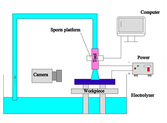
Figure 1.
Schematic diagram of the experimental setup.
As shown in Figure 1, the experimental setup mainly contains an electrolyte circulation module and a motion control module. The electrolyte circulation module consists of a circulation pipe, a pressure control valve, a pressure sensor, a temperature sensor, and a reservoir, which is an important part of processing and real-time feedback. The motion control module is mainly responsible for the motion control of the workpiece and the nozzle, realizing the control of the processing parameters (such as the flow rate, speed, and direction of the ejection), and it is capable of monitoring and adjusting the parameters of the processing in real time.
To obtain the desired surface topography, a blue oil mask with skeletonized patterns is covered on the anode workpiece, and the nonmasked areas on the surface of the workpiece react with the electrolyte under the impact of a high-pressure jet electrolyte. This method improves the processing flexibility of EJM. The EJM schematic is shown in Figure 2.
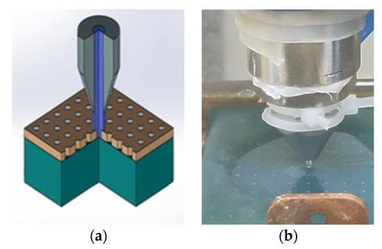
Figure 2.
EJM schematic: (a) machining schematic; (b) actual machining diagram.
As shown in Figure 2, the metal workpiece is positively charged, the nozzle is negatively charged, and the electrolyte is sprayed through the nozzle to form a jet, forming a closed-loop current. The anode workpiece part of the surface does not react due to the mask coverage, while the nonmasked area reacts with the electrolyte and gradually dissolves. The lateral feed and longitudinal movement of the cathode nozzle can adjust the processing time and processing gap, while changing the size of the nozzle hole diameter can control the jet diameter for electrolytic processing.
2.2. Theoretical Derivation of Machining Efficiency
Electrolytic processing follows Faraday’s law, which consists of two main points:
At the metal/solution interface (at the interface of the two cathodes), the mass of the substance involved in the electrochemical reaction is proportional to the amount of electricity passing across its interface, as shown in Equation (1).
- M—Anode dissolved mass (g);
- K—Elemental mass electrochemical equivalent (g/A·s);
- Q—Electricity through the anode-cathode interface (A·s);
- I—Current intensity (A);
- t—Current action time (S).
Different substances per unit mass reacting in an electrolyte consume the same amount of electricity, and the total charge consumed is recorded as Faraday’s constant, denoted F, F ≈ 1608.3 (A·min/mol). The elemental mass electrochemical equivalent K can be introduced from Faraday’s constant, as shown in Equation (2).
- A—Relative atomic mass of metallic elements;
- n—Atomic weight of an element.
Therefore, the bulk electrochemical equivalent ω [cm3/(A·s)] of this element is shown in Equation (3).
—Metal density (g/cm3).
The volume of anode metal dissolved is obtained from Equation (3), as shown in Equation (4).
V—Volume of dissolved metal at the anode (cm3).
In practice, the dissolution rate of the anode workpiece is often measured in terms of the machining speed, i.e., the speed at which the material is removed, denoted as . This speed is measured in the direction normal to the surface of the workpiece.
Since the anode workpiece for electrolytic processing is usually an alloy material, the actual processing will produce chemical reactions of multiple metals, as well as different chemical valence changes, and the theoretical calculations are based on the specified metal with only specific atomic valence changes. The side reactions occurring in the actual processing will consume a certain amount of power, making the actual dissolution volume of the metal smaller than the theoretical dissolution volume. To calculate the actual utilization rate of the total power consumed by the dissolution of the target metal through the anode, the current efficiency is introduced, as shown in Equations (5)–(7).
Therefore, the actual electrolytic processing speed needs to take into account the current efficiency , as shown in Equation (8).
- —Electrolytic machining speed in the normal direction (mm/s);
- —Current efficiency;
- i—Current density (A/mm2).
From Equation (8), the electrolytic processing speed () is positively correlated with the current efficiency , the volumetric electrochemical equivalent of the element (), and the current density (i).
3. Simulation Analysis
In the process of jet electrolytic machining, pulse voltage, machining gap, and machining time are important factors affecting the machining efficiency and machining quality. With the help of COMSOL 6.1 software, a simulation model is constructed to initially investigate the processing law under mask conditions and provide a reference parameter range for subsequent actual processing.
3.1. Multiple Physical Field Coupling
In the preprocessing stage, the simulation model is established according to Figure 2, as shown in Figure 3a, and the initial values of primary current distribution, rarefied matter transfer, laminar flow phenomenon, and physical fields are set. To ensure that the simulation is carried out smoothly, the assumptions to be made are the electrolyte conductivity, temperature, and concentration are stable and unchanged at any position. The electrolyte is a continuously flowing fluid and is incompressible. The initial values of the simulation parameters are shown in Table 1.
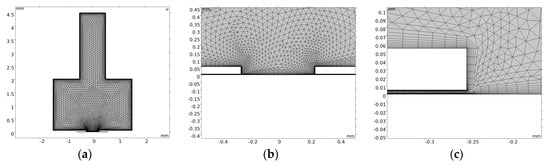
Figure 3.
Simulation model meshing and local enlargement: (a) 3D Mesh1; (b) 3D Mesh2; (c) 3D Mesh3.

Table 1.
Discharge Situation Table.
Based on the above assumptions, the electric field is simplified to a constant electric field, and the electric field at any point P(x, y) in the processing region Ω conforms to the Laplace equation.
In Equation (9): —Potential at points in the processing region.
The Laplace equation boundary conditions are shown in Equation (10).
- E—Anodic surface potential;
- n—Normalcy coordinates;
- —Anode boundary;
- —Cathode boundary;
- —Insulated boundary.
To improve the accuracy of the simulation results, different meshing methods were used for different regions of the simulation model, with the geometrical boundaries of the 2D model being delineated using a layer mesh and the intermediate regions by a triangular mesh. In addition, the anode region, where the electrolytic processing reaction occurs, is also refined. To speed up the convergence and shorten the simulation computation time, a gap of 5 μm was set between the mask and the anode surface, as shown in Figure 3.
In the postprocessing stage, the solved simulation data need to be processed. The potential cloud and current density line graphs are plotted based on the potential and current density values of the electrolyte, respectively, and are used to explore the distribution and trend of the potential and the electrolytic reaction rate of the anode material.
3.2. Simulation Analysis of Electric Field Distribution
3.2.1. Simulation Analysis of Electric Field Distribution
The pulse voltages are set to be 50 V, 75 V, 100 V, and 125 V. The electric field simulation models of different pulse voltages are established, and the electric field simulation analysis is carried out. The corresponding potential cloud and current density graphs are shown in Figure 4.
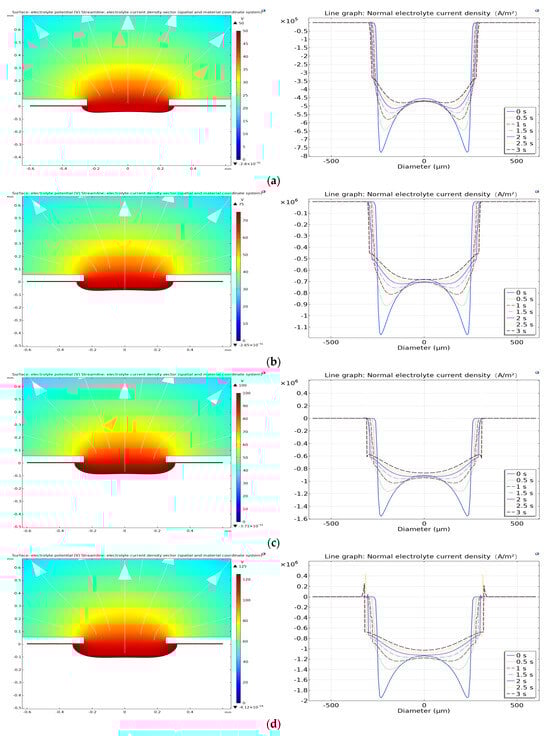
Figure 4.
Potential cloud and current density graphs corresponding to different voltages: (a) 50 V; (b) 75 V; (c) 100 V; (d) 125 V.
From the potential cloud map, it can be seen that the color shows a gradual trend, in which the interior of the micropit has the darkest color, which changes from dark to light along the direction of the electric field lines. The potential distribution inside the micropit is uniform and shows a decreasing trend, and the change in pulse voltage does not affect the uniformity of the potential distribution. Due to the insulating effect of the mask, only the charged metal surface in the nonmask region reacts with the electrolyte. The closer to the center of the mask hole, the higher the potential, and the highest potential is at the anode workpiece, and it is infinitely close to the applied external voltage, while the potential at the cathode nozzle is 0 V.
As can be seen from the current density line graph, under the condition of constant voltage, the current density at the beginning of machining is maximum, and with the extension of machining time, the current density gradually decreases. The current density line is in the shape of horns, and with the extension of the processing time, the difference between the maximum value and minimum value of the current density gradually decreases. The current density line becomes flat, and the horns become smaller. When the pulse voltage was increased from 50 V to 125 V, the average current density inside the micropit increased, and the electrolytic processing speed increased.
3.2.2. Simulation Analysis of Electric Field with Different Machining Gaps
The machining gaps are set to be 0.5 mm, 1 mm, 1.5 mm, and 2 mm, and the electric field simulation models with different machining gaps are established for electric field simulation analysis. The corresponding voltage cloud and current density profiles are shown in Figure 5.
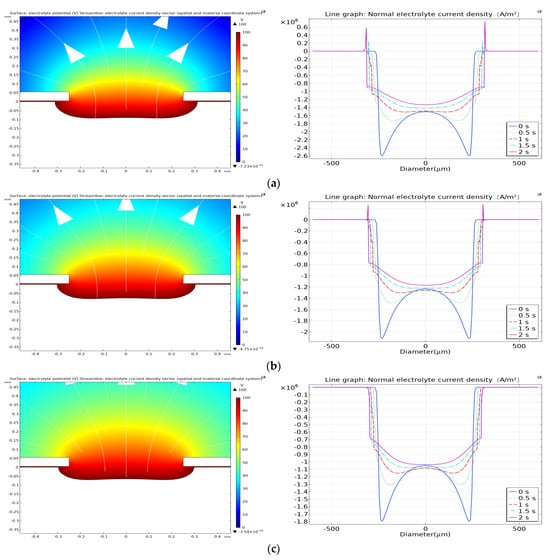
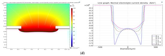
Figure 5.
Voltage maps and current density profiles corresponding to different machining gaps: (a) 0.5 mm; (b) 1 mm; (c) 1.5 mm; (d) 2 mm.
From the potential cloud diagram, it can be seen that the potential distribution inside the micropit is uniform and shows a decreasing trend along the electric field lines. The potential is the highest at the anode workpiece, and the potential at the cathode nozzle is 0 V. The variation in the machining gap does not affect the uniformity of the potential distribution.
From the current density line graph, the current density at the initial machining is maximum when the machining gap is constant. With the extension of machining time, the current density gradually decreases. As the machining time increases, the difference between the maximum and minimum values of the current density gradually decreases, and the current density line becomes flatter. When the machining gap increases from 0.5 mm to 2 mm, the average current density inside the micropit decreases, and the electrolytic machining speed decreases.
3.2.3. Simulation Analysis of Electric Field with Different Processing Time
The machining time is set to be 1 s, 2 s, and 3 s. The electric field simulation model with different machining times is established, and the electric field simulation analysis is carried out. The corresponding voltage cloud and current density profiles are shown in Figure 6.
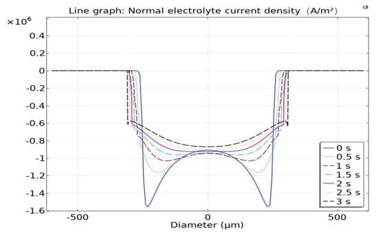
Figure 6.
Current density profiles corresponding to different machining times.
As can be seen from Figure 6, the longer the processing time, the flatter the current density line. The current density decreases from 1.55 × 10⁶ A/m2 to 0.9 × 10⁶ A/m2 with longer processing time, and the electrolytic processing speed decreases.
4. Experimental Research
The experiments were performed using an array-hole blue oil mask, and the prepared surface microstructures were arrays of micropits with a large number of micropits, which could be reduced by chance by randomly measuring multiple micropits. The mask schematic is shown in Figure 7.
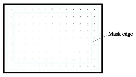
Figure 7.
Mask schematic.
As shown in Figure 7, since the effect is unstable when micropits are processed through the holes at the edge of the mask, after excluding the edge of the mask, a randomly selected processed pit in each row is measured, and the detection data are obtained and recorded. The experiments were repeated three times for each set of one-factor experiments using scanning processing.
4.1. Parameter Indicators
To determine the definiteness of the jet electrolytic processing, it is necessary to introduce the corrosion factor EF, as shown in Equation (11).
In Equation (11), H is the depth of the micropit, D is the diameter of the micropit, is the diameter of the mask aperture, and ∆D is the difference between the diameter of the micropit and the diameter of the mask aperture. It can be seen that the larger H is, the smaller ∆D is, and the larger EF is, the closer the shape of the micropit formed by processing is to the shape of the mask skeleton, and the higher the replication accuracy. To better represent the dimensional changes in the micropit, the evaluation indexes of micropit depth H, diameter D, material removal rate MRR, and erosion factor EF are used to describe the processing efficiency and processing quality.
4.2. Experimental Results and Discussion
Aiming at the pulse voltage, machining gap, machining time, and other processing parameters for three repetitions of single-factor experiments, the experimental results ar analyzed and the law is summarized.
4.2.1. Effect of Pulse Voltage on Micropit Structure
Voltages of 50 V, 75 V, 100 V, and 125 V were selected for the electrolytic machining process experiments, in which the fixed parameters were a machining gap of 2 mm, a jet diameter of 1 mm, and a mask aperture diameter of 500 μm. The depths and diameters of the micropits machined by different pulse voltages are shown in Table 2.
Table 2.
Mean values of diameter and depth of micropits at different pulse voltages.
The machining depth and diameter of the micropits are an important basis for analyzing the machining efficiency and machining quality. To more intuitively compare the depth and width of the micropit corresponding with the nonpulsed voltage, the average depth and width formed by each of the above voltages are plotted as a relationship graph, as shown in Figure 8.
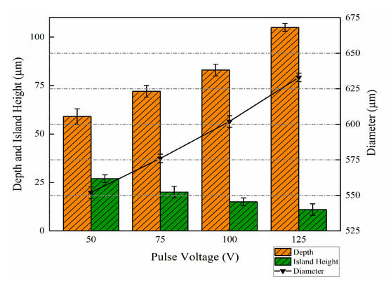
Figure 8.
Plot of pulse voltage versus micropit size.
As shown in Figure 8, the primary longitudinal coordinate axes indicate the values of micropit depth and island height, which are represented by bar graphs, and the secondary longitudinal coordinates indicate the micropit diameters, which are represented by line graphs.
As shown in Table 2 and Figure 8, with the increasing peak pulse voltage, the average diameter of the micropit increases from 552 μm at 50 V to 633 μm at 125 V, with an increase of 14.67%; the average depth of the micropit increases from 59 μm at 50 V to 105 μm at 125 V, with an increase of 77.97%; and the height of the island decreases from 27 μm at 50 V to 11 μm at 125 V. The average depth of the micropit decreases by 77.97%. The island height decreased from 27 μm at 50 V to 11 μm at 125 V, a decrease of 59.26%. To further investigate the processing morphology, the micropits were observed in three dimensions using a laser confocal microscope, as shown in Figure 9.
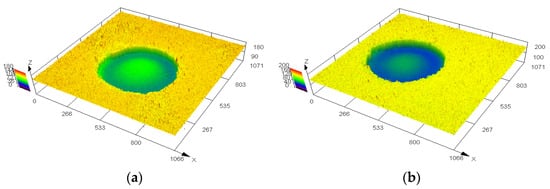
Figure 9.
Comparison of 3D contours corresponding to different voltages: (a) 75 V; (b) 100 V.
As can be seen from Figure 9, the perpendicularity of the inner wall of the micropit corresponding to both 75 V and 100 V pulse voltages is better, and the inner wall is equally smooth. The increase in the peak pulse voltage breaks the mask to a lesser extent, the circular replication accuracy changes very little, and the mask remains well constrained. To further compare its islanding effect and the amount of side-etching, a schematic diagram of the micropit cross-section measurement is drawn, as shown in Figure 10.
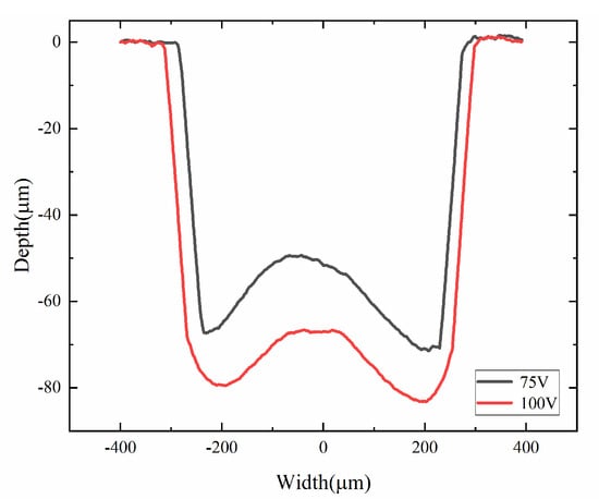
Figure 10.
Measured micro-pit cross section corresponding to pulse voltages of 75 V and 100 V.
As can be seen in Figure 10, the inner walls of the 100 V processed pits are more perpendicular and have less lateral etching. In contrast, the top and bottom of the 75 V processed pits have more drastic variations in the amount of lateral etching, and the cross-sectional shape is closer to a “W”. The 100 V processed pits have smaller values for the heights of the isolated peaks, less islanding, and a flatter bottom.
4.2.2. Effect of Machining Gap on Micropit Structure
Machining gaps of 0.5 mm, 1 mm, and 1.5 mm were selected for the electrolytic machining process experiments, in which the fixed parameters were a pulse voltage of 100 V, a jet diameter of 1 mm, and a mask aperture diameter of 500 μm. The average depths and diameters of the micropits corresponding to different machining gaps are shown in Table 3.
Table 3.
Mean values of diameter and depth of micropits at different machining gaps.
The machining depth and diameter of the micropits are an important basis for analyzing the machining efficiency and machining quality. To more intuitively compare the depth and width of the micropits corresponding to the nonpulsed voltage, the average depth and width formed by each of the above voltages are plotted as a relationship graph, as shown in Figure 11.
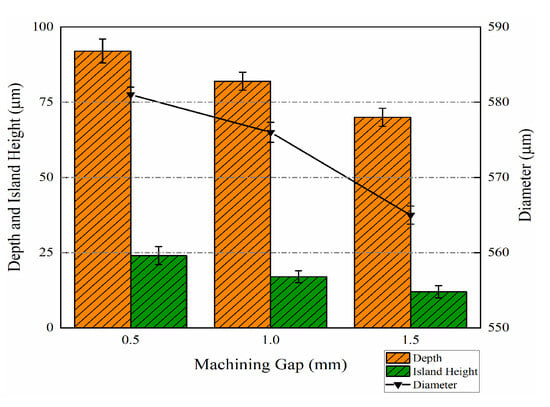
Figure 11.
Plot of machining clearance versus micropit size.
As shown in Figure 11, the primary longitudinal coordinate axes indicate the values of micropit depth and island height, which are represented by bar graphs, and the secondary longitudinal coordinates indicate the diameter of the micropit, which is represented by a line graph.
As seen in Table 3 and Figure 11, with the increase in machining clearance, the average diameter of the micropit decreases from 581 μm under 0.5 mm to 535 μm under 1.5 mm, which is a reduction of 7.92%; the average depth of the micropit decreases from 92 μm under 0.5 mm to 70 μm under 1.5 mm, which is a reduction of 23.91%; and the height of the silo decreases from 24 μm under 0.5 mm to 12 μm at 1.5 mm, a reduction of 50.00%.
To further study its machining morphology, the micropits were observed in three dimensions using a laser confocal microscope, as shown in Figure 12.
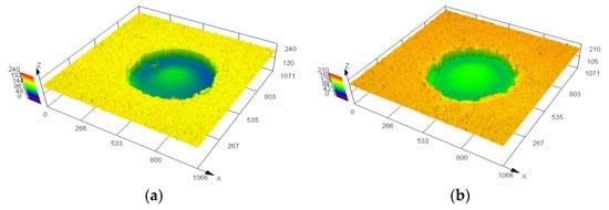
Figure 12.
Comparison of 3D contours corresponding to different machining gaps: (a) 0.5 mm; (b) 1 mm.
From Figure 12, it can be seen that the inner wall of the micropit with a machining gap of 0.5 mm is more perpendicular, and the inner wall is smoother and flatter compared with that corresponding to 1 mm. With a machining gap of 0.5 mm, the mask is better constrained, the micropit periphery is better flattened, and the circular replication accuracy is higher. In order to further compare their islanding effect and the amount of side erosion, a schematic diagram of the micropits’ cross-section measurements is drawn, as shown in Figure 13.
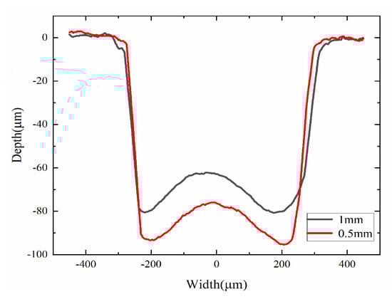
Figure 13.
Measured micro-pit cross section corresponding to machining gaps of 0.5 mm and 1 mm.
As can be seen in Figure 13, compared with 1 mm, the 0.5 mm machining gap corresponds to a significantly larger depth in the micropit, with less side-etching and higher perpendicularity of the inner wall. At the same time, the bottom of the 0.5 mm machined micropit is also flatter, with smaller values of the heights of the isolated peaks, and the island effect is weakened.
4.2.3. Effect of Machining Time on Micropit Structure
The processing times of 1 s, 2 s, and 3 s were selected for the electrolytic machining process experiments, and the depths and diameters of the micropits corresponding to different processing times are shown in Table 4.
Table 4.
Mean values of diameter and depth of micropits at different machining times.
The machining depth and diameter of the micropits are an important basis for analyzing the machining efficiency and machining quality. To more intuitively compare the depth and width of the micropits corresponding to the nonpulsed voltage, the average depth and width formed by each of the above voltages are plotted as a relationship graph, as shown in Figure 14.
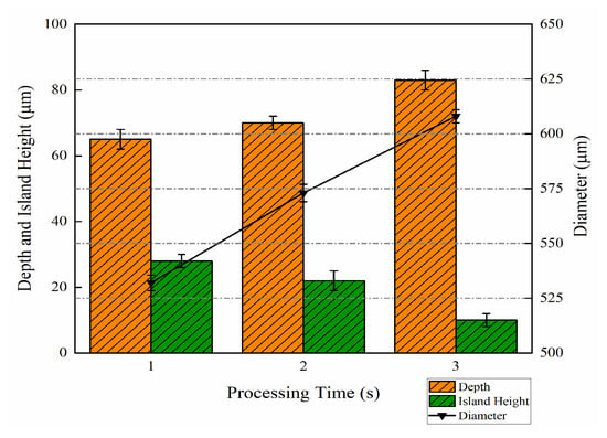
Figure 14.
Plot of machining time vs. micropit size.
As shown in Figure 14, the primary longitudinal coordinate axes indicate the values of the micropit depths and island heights, which are represented by bar graphs, and the secondary longitudinal coordinates indicate the micropit diameters, which are represented by line graphs.
As shown in Table 4 and Figure 14, the average diameter of the micropit increases from 532 μm under 1 s to 608 μm under 3 s, which is an increase of 14.29%; the average depth of the micropit increases from 65 μm under 1 s to 83 μm under 3 s, which is an increase of 27.69%; and the height of the silo decreases from 28 μm under 1 s to 10 μm under 3 s, which is a decrease of 64.29%.
To further study their machining morphology, the micropits were observed in three dimensions using a laser confocal microscope, as shown in Figure 15.
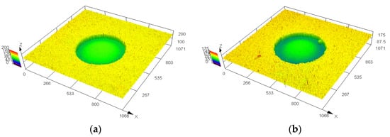
Figure 15.
Comparison of 3D contours corresponding to different machining times: (a) 1 s; (b) 2 s.
From Figure 15, it can be seen that the micropits processed with a processing time of 1 s and 2 s are as regular as each other, and the inner walls of the micropits are equally smooth. When the processing time is extended from 1 s to 2 s, the mask still maintains a good confinement effect, high circular replication accuracy, and good flatness around the micropit. To further compare their islanding effect and the amount of side erosion, a schematic diagram of the micropits’ cross-section measurements is drawn, as shown in Figure 16.
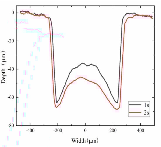
Figure 16.
Measured micro-pit cross section corresponding to machining times of 1 s and 2 s.
As can be seen from Figure 16, the increase in the amount of lateral etching at a processing time of 2 s is very small and negligible. In contrast, the change in lateral etch volume is more pronounced for the micropits processed at 1 s. The value of the height of the isolated peak at the bottom of the micropits processed at 2 s is much smaller, and the islanding effect is weaker.
After the experimental study, under the conditions of a pulse voltage of 100 V, a machining gap of 0.5 mm, and a machining time of 2 s, the jet electrolytic machining of array micropits shows a better machining rate and machining quality. The experimental results are shown in Figure 17.
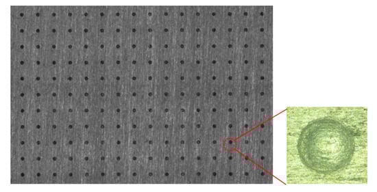
Figure 17.
Pit arrays machined with optimal parameter combinations.
From Figure 17, it can be seen that the pit arrays machined by the optimal parameter combination have a regular shape and good surface quality.
5. Conclusions
In this paper, we use jet electrolytic processing technology to experimentally study the surface microtexture of medical materials, optimize the process of preparing high-precision medical devices with this technology, and summarize the following conclusions.
- (1)
- Based on COMSOL software, the electric field simulation model with different processing parameters (pulse voltage, processing gap, and processing time) is constructed, and the results show that increasing the pulse voltage, decreasing the processing gap, and prolonging the processing time can improve the electrolytic machining speed.
- (2)
- The contribution of 125 V pulse voltage to the depth of the micropits increased by 77.96% over 50 V, the contribution to the diameter increased by 14.67%, and the height of the island decreased by 59.26%. Increasing the pulse voltage, the micropits still maintain a more regular shape. The machining efficiency and quality of machining is better with higher voltage.
- (3)
- The contribution of 1 mm machining clearance to the depths of micropits decreases them by 23.91%, the contribution to the diameter increases by 7.91%, and the island height decreases by 50.00% compared with that of 0.5 mm. A reasonable reduction in the machining gap can attenuate the islanding effect and improve the micropits’ circular replication accuracy.
- (4)
- The contribution of 3 s machining time to depth increased it by 27.69%, width by 14.29%, and silo height by 64.29% compared with 1 s. Extending the machining time improves the quality of machining.
Author Contributions
Conceptualization, C.C.; methodology, C.C.; software, C.C. and X.S.; validation, C.C. and X.S.; formal analysis, C.C. and X.L.; investigation, J.G.; resources, C.C.; data curation, Z.Y. and Z.C.; writing—original draft preparation, C.C. and X.S.; writing—review and editing, C.C.; visualization, C.C.; supervision, Z.J.; project administration, Z.J.; funding acquisition, C.C. All authors have read and agreed to the published version of the manuscript.
Funding
This work was supported by the Foundation of Guangzhou Higher Education Quality and Reform Project (2023CJRHJD002), Key Research Platforms and Projects of Guangdong General Universities (No. 2023ZDZX2051), Guangdong Province Undergraduate Teaching Quality and Teaching Reform Project (Yue Jiao Gao Han [2024] No. 9), Guangdong Provincial Natural Science Foundation (Youth Enhancement Project) 2024A1515030159.
Institutional Review Board Statement
Not applicable.
Informed Consent Statement
Not applicable.
Data Availability Statement
Data are contained within the article.
Conflicts of Interest
The authors declare no conflicts of interest.
References
- Xiao, L.; Li, J.; Mieszkin, S.; Di Fino, A.; Clare, A.S.; Callow, M.E.; Callow, J.A.; Grunze, M.; Rosenhahn, A.; Levkin, P.A. Slippery Liquid-Infused Porous Surfaces Showing Marine Antibiofouling Properties. ACS Appl. Mater. Interfaces 2013, 5, 10074–10080. [Google Scholar] [CrossRef] [PubMed]
- Wilson, P.W.; Lu, W.; Xu, H.; Kim, P.; Kreder, M.J.; Alvarenga, J.; Aizenberg, J. Inhibition of ice nucleation by slippery liquid-infused porous surfaces (SLIPS). Phys. Chem. Chem. Phys. 2013, 15, 581–585. [Google Scholar] [CrossRef] [PubMed]
- Zhou, X.; Lee, Y.-Y.; Chong, K.S.L.; He, C. Superhydrophobic and slippery liquid-infused porous surfaces formed by the self-assembly of a hybrid ABC triblock copolymer and their antifouling performance. J. Mater. Chem. B 2018, 6, 440–448. [Google Scholar] [CrossRef] [PubMed]
- Luo, J.T.; Geraldi, N.R.; Guan, J.H.; McHale, G.; Wells, G.G.; Fu, Y.Q. Slippery Liquid-Infused Porous Surfaces and Droplet Transportation by Surface Acoustic Waves. Phys. Rev. Appl. 2017, 7, 014017. [Google Scholar] [CrossRef]
- Liu, Y.; Qu, N. Investigation on the performance of macro electrochemical machining of the end face of cylindrical parts. Int. J. Mech. Sci. 2020, 169, 105333. [Google Scholar] [CrossRef]
- Hackert-Oschätzchen, M.; Meichsner, G.; Zinecker, M.; Martin, A.; Schubert, A. Micromachining with continuous electrolytic free jet. Precis. Eng. 2012, 36, 612–619. [Google Scholar] [CrossRef]
- Zhang, X.; Song, X.; Ming, P.; Li, X.; Zeng, Y.; Cai, J. The Effect of Electrolytic Jet Orientation on Machining Characteristics in Jet Electrochemical Machining. Micromachines 2019, 10, 404. [Google Scholar] [CrossRef] [PubMed]
- Jimenez-Durango, C.; Reyes-Vera, E.; Usuga-Restrepo, J.; Montoya-Cardona, J.; Restrepo, J.F.; Gomez-Cardona, N.; Huertas-Herrera, B.; Varon, M. A Novel Interferometric Sensor Based on a Dual- Core Transversally Chirped Microstructured Optical Fiber for Measuring Glucose Concentration. In Proceedings of the 2018 International Conference on Electromagnetics in Advanced Applications (ICEAA), Cartagena, Colombia, 10–14 September 2018; pp. 531–534. [Google Scholar]
- Haleem, A.; Javaid, M.; Khan, R.H.; Suman, R. 3D Printing Applications in Bone Tissue Engineering. J. Clin. Orthop. Trauma 2020, 11, S118–S124. [Google Scholar] [CrossRef] [PubMed]
- Wong, T.-S.; Wang, S.-H.; Tang, S.-K.-Y.; Aizenberg, J. Bioinspired self-repairing slippery surfaces with pressure-stable omniphobicity. Nature 2011, 477, 443–447. [Google Scholar] [CrossRef]
- Wang, Y.; Zhang, H.; Liu, X.; Zhou, Z. Slippery liquid-infused substrates: A versatile preparation unique anti-wetting and dragreduction effect on water. J. Mater. Chem. A 2016, 4, 2524–2529. [Google Scholar] [CrossRef]
- Yu, W. Experimental Study on Micro-Structure Machining by Electrohydraulic Beam. Master’s Thesis, Dalian University of Technology, Dalian, China, 2013. [Google Scholar]
- Guo, C.; Zhou, A.; He, J.; Xiao, H.; Li, D. An Investigation in Sub-Millimeter Channel Fabrication by the Non-Aqueous Electrolyte Jet Machining of Zr-Based Bulk Metallic Glasses. Micromachines 2023, 14, 2232. [Google Scholar] [CrossRef] [PubMed]
- He, J.; Wang, Z.; Zhou, W.; Jian, Y.; Zhou, L. Electrolytic Characteristics of Microhole Array Manufacturing Using Polyacrylamide Electrolyte in 304 Stainless Steel. Micromachines 2023, 14, 1808. [Google Scholar] [CrossRef] [PubMed]
- Li, D.; Ming, P.; Niu, S.; Yang, G.; Cheng, K. Fabricating Precise and Smooth Microgroove Structures on Zr-Based Metallic Glass Using Jet-ECM. Micromachines 2024, 15, 497. [Google Scholar] [CrossRef] [PubMed]
- Niu, S.; Huang, K.; Ming, P.; Wang, S.; Zhao, F.; Qin, G.; Liu, H. Jet Electrochemical Micromilling of Ti-6Al-4V Using NaCl–Ethylene Glycol Electrolyte. Micromachines 2024, 15, 173. [Google Scholar] [CrossRef] [PubMed]
- Zaki, S.; Zhang, N.; Gilchrist, M.D. Electropolishing and Shaping of Micro-Scale Metallic Features. Micromachines 2022, 13, 468. [Google Scholar] [CrossRef] [PubMed]
- Sikdar, S.; Menezes, P.V.; Maccione, R.; Jacob, T.; Menezes, P.L. Plasma Electrolytic Oxidation (PEO) Process—Processing, Properties, and Applications. Nanomaterials 2021, 11, 1375. [Google Scholar] [CrossRef] [PubMed]
- Smyslova, M.K.; Valiev, R.R.; Smyslov, A.M.; Modina, I.M.; Sitdikov, V.D.; Semenova, I.P. Microstructural Features and Surface Hardening of Ultrafine-Grained Ti-6Al-4V Alloy through Plasma Electrolytic Polishing and Nitrogen Ion Implantation. Metals 2021, 11, 696. [Google Scholar] [CrossRef]
- Zhao, C.; Ming, P.; Zhang, X.; Qin, G.; Shen, J.; Yan, L.; Zheng, X.; Cao, J. Through-Mask Electrochemical Micromachining with Reciprocating Foamed Cathode. Micromachines 2020, 11, 188. [Google Scholar] [CrossRef] [PubMed]
- Chen, C.; Wu, S.; Zhang, T.; Wang, Y.; Shao, X.; Mo, F. Experimental Study of Electrolytic Processing of Discharge-Assisted Jet Masks. Coatings 2023, 13, 1280. [Google Scholar] [CrossRef]
- Chen, C.; Wu, S.; Wu, H.; Shan, L.; Li, K.; Wu, S. Discharge Characteristics and Mechanisms of Electrolytic Discharge Processing by Jet Mask. Coatings 2023, 13, 1933. [Google Scholar] [CrossRef]
- Evangelista, I.; Wencel, D.; Beguin, S.; Zhang, N.; Gilchrist, M.D. Influence of Surface Texturing on the Dry Tribological Properties of Polymers in Medical Devices. Polymers 2023, 15, 2858. [Google Scholar] [CrossRef] [PubMed]
- Cai, G.; Zeng, Q.; Wu, T. Effect of Surface Microstructure on the Long-term Anti-bacterial Performance for Slippery Liquid Infused Porous Surfaces. In Proceedings of the 2020 IEEE SENSORS, Rotterdam, The Netherlands, 25–28 October 2020; pp. 1–4. [Google Scholar]
- Wu, M.; Kumar Saxena, K.; Guo, Z.; Qian, J.; Reynaerts, D. Fast Fabrication of Complex Surficial Micro-Features Using Sequential Lithography and Jet Electrochemical Machining. Micromachines 2020, 11, 948. [Google Scholar] [CrossRef] [PubMed]
- Zheng, B. Preparation and Performance of Anti-Bioadhesive Surfaces for Medical Devices. Master’s Thesis, China University of Geosciences Beijing, Beijing, China, 2021. [Google Scholar]
- Liang, C. Multi-stage micro-nano-structured antibacterial composite coatings on metal implantable medical device surfaces. In Proceedings of the ASTF 2023 (5th) Antimicrobial Science and Technology Forum, Shenyang, China, 9–11 August 2023; Hebei University of Technology: Tianjin, China, 2023; p. 1. [Google Scholar]
- Yan, L. Characterization of Puncture Resistance of Bionic Medical Needles. Master’s Thesis, Jilin University, Jilin, China, 2011. [Google Scholar]
Disclaimer/Publisher’s Note: The statements, opinions and data contained in all publications are solely those of the individual author(s) and contributor(s) and not of MDPI and/or the editor(s). MDPI and/or the editor(s) disclaim responsibility for any injury to people or property resulting from any ideas, methods, instructions or products referred to in the content. |
© 2024 by the authors. Licensee MDPI, Basel, Switzerland. This article is an open access article distributed under the terms and conditions of the Creative Commons Attribution (CC BY) license (https://creativecommons.org/licenses/by/4.0/).