Article

Failure of Electron Beam Physical Vapor Deposited Thermal Barrier Coatings System under Cyclic Thermo-Mechanical Loading with a Thermal Gradient

1
Beijing Key Laboratory of Aeronautical Materials Testing and Evaluation, Key Laboratory of Aeronautical Materials Testing and Evaluation AECC, AVIC Failure Analysis Center, AECC Beijing Institute of Aeronautical Materials, P.O. Box 81-4, Beijing 100095, China
2
Aviation Key Laboratory of Science and Technology on Advanced Corrosion and Protection for Aviation Material, AECC Beijing Institute of Aeronautical Materials, P.O. Box 81-5, Beijing 100095, China
3
School of Materials Science and Engineering, Shanghai Jiao Tong University, Shanghai 200240, China
*
Author to whom correspondence should be addressed.
Coatings 2024, 14(7), 902; https://doi.org/10.3390/coatings14070902
Submission received: 20 May 2024 / Revised: 15 July 2024 / Accepted: 17 July 2024 / Published: 18 July 2024

Abstract

:
The failure mechanism of a thermal barrier coatings (TBCs) system is investigated using cyclic thermo-mechanical loading with a thermal gradient. Hollow circular cylindrical specimens are employed, consisting of a nickel-based single-crystal alloy DD6 coated with a NiCoCrAlYHf bond coat via arc-ion plating and a surface electron beam physical vapor deposited (EB-PVD) yttria-stabilized zirconia topcoat. The experimental setup allows for a surface temperature of 1130 °C and a substrate temperature of 1070 °C, while a tensile mechanical load of 200 MPa is employed to simulate the centrifugal stress in the middle of the high-pressure turbine blade. The comparison between TBCs with and without mechanical loading implies that the coupled thermo-mechanical load significantly promotes coating spallation since the superposition of mechanical strain enhances the local tensile stress at the peak region of the topcoat/thermally grown oxides (TGOs) interface. A subsequent interfacial morphology analysis demonstrates that the topcoat/TGO interface exhibited a degradation in the direction parallel to the mechanical loading axis. For all the specimens, TGO comprises a duplex structure, consisting of outer spinel and inner α-Al2O3.

1. Introduction

To improve the performance and efficiency of gas turbine engines under conditions associated with extreme stress, thermal loads, and vibrational effects, many attempts have been made to gradually increase the inlet temperature. In that regard, thermal barrier coatings (TBCs), consisting of a metal bond coat and a ceramic topcoat, have been widely employed as a surface protection to improve the operation temperature of Ni-based superalloys [1,2,3,4].
Spallation of the topcoat is a critical issue from the viewpoint of engine durability [5,6]. To evaluate the performance of TBCs, it is necessary to simulate the engine operating conditions in the laboratory environment. Burner rig tests operating with fuel gas (propane or acetylene)/oxygen mixture are generally used to evaluate the thermal cycling behavior of the systems [7,8,9]; however, there are two drawbacks to the commonly used facilities: (i) the gas velocity is usually insufficient to evaluate the gas impact or erosion resistance of the coatings; (ii) it is unable to simulate the cyclic mechanical loading together with the cyclic temperature gradient, not to mention the chemical factors (e.g., calcium–magnesium–alumino-silicate (CMAS) corrosion). This deviation between the real and the laboratorial condition hinders the accurate evaluation of TBCs. For these purposes, it is necessary to employ a multifactor coupled facility for the TBCs performance and failure mechanism analysis to establish sound lifetime prediction models.
It is generally accepted that the TBCs’ degradation is associated with a progressive roughening (or rumpling) of the bond coat surface along with the thermally grown oxide (TGO). The out-of-plane displacement accompanying rumpling results in tensile stress around the undulation peaks that can initiate interfacial cracking and eventually the failure of TBCs. Previously, investigations suggested that the TBCs failure mechanism under thermo-mechanical loading condition was obviously different from that of a statistic thermo-cyclic case [10,11,12,13,14]. Baufeld et al. [15,16] studied the effect of phase difference between the applied thermal and mechanical loading; in an in-phase test, the buckling and delamination of coatings is the main pattern, while in an out-of-phase test, the fatigue cracks initiated from the bond coat/TGO interface control the failure. Usually, an axial load along the length of the specimen is applied, resulting in segmentations of the coatings that are perpendicular to the loading [17]. Shi et al. [18] investigated the morphological surface instabilities on bond coat and emphasized the importance of temperature gradient and axial load on the interfacial undulation. Despite the different failure behaviors, an interfacial instability under thermo-mechanical loading is well recognized.
DD6 is a low-cost second-generation single-crystal superalloy proposed and produced by AECC Beijing Institute of Aeronautical Materials [19]. NiCoCrAlYHf bond coat is typically used as a bond coat material due to its excellent oxidation resistance and its improvement in the bonding between the ceramic topcoat and superalloy substrate [20,21]. In our previous work, we have investigated the effects of the coating pre-treatment and the interdiffusion between coating and substrate on the surface recrystallization behavior of the NiCoCrAlYHf/DD6 system [22]. Here, the purpose of this work is to study the process of the destruction of the YSZ/NiCoCrAlYHf/DD6 system under cyclic thermo-mechanical loading with a temperature gradient using a multifactor coupling test facility.
The experimental sets of the multifactor coupling test are shown in Figure 1. A kerosene-fueled combustor system was employed to generate the desired jets, and the simulated flame has a maximum temperature of 1700 °C and a maximum speed of Mach 0.8. This facility can perform tests involving thermal shock, thermal cycling, gas impact, and erosion/corrosion, during which the specimens were fixed by a loading system for a further rotation, tensile/compressive loading, and internal cooling. The objective of this work is to investigate the failure mechanism under a cyclic thermo-mechanical test with a thermal gradient. The growth and morphology of TGO are elucidated with X-ray tomography, and the comparison between the specimen with and without mechanical strain is supposed to promote the understanding of TBCs lifetime controlling in an actual service condition.

2. Materials and Methods

2.1. TBCs Preparation

DD6 single-crystal superalloy was selected as the substrate of TBCs. The annealed DD6 superalloy was machined into hollow rods with an outer/inner diameter of 6.5 mm/4.5 mm, respectively, and a gauge length of 40 mm (detailed geometry of the specimens used for this study is given by CAD drawing (CAD 2007) in Appendix A). A 25 μm NiCoCrAlYHf bond coat was deposited via arc-ion plating technology (AIP-PVD, A-1000, Russia) at a deposition rate of about 0.3–0.5 μm/min. All NiCoCrAlYHf-coated specimens were then annealed under vacuum at 900 ± 10 °C for 3 h to facilitate the interdiffusion and enhance the bonding strength between the bond coat and the substrate. Ultimately, electron beam physical vapor deposition technology (EB-PVD, UE-207 S, Ukraine) was employed to deposit 120 μm YSZ (6–9 wt.% Y2O3) coatings onto the bond coats at a deposition rate of 4–5 μm/min. The nominal chemical compositions of DD6 and NiCoCrAlYHf are displayed in Table 1.

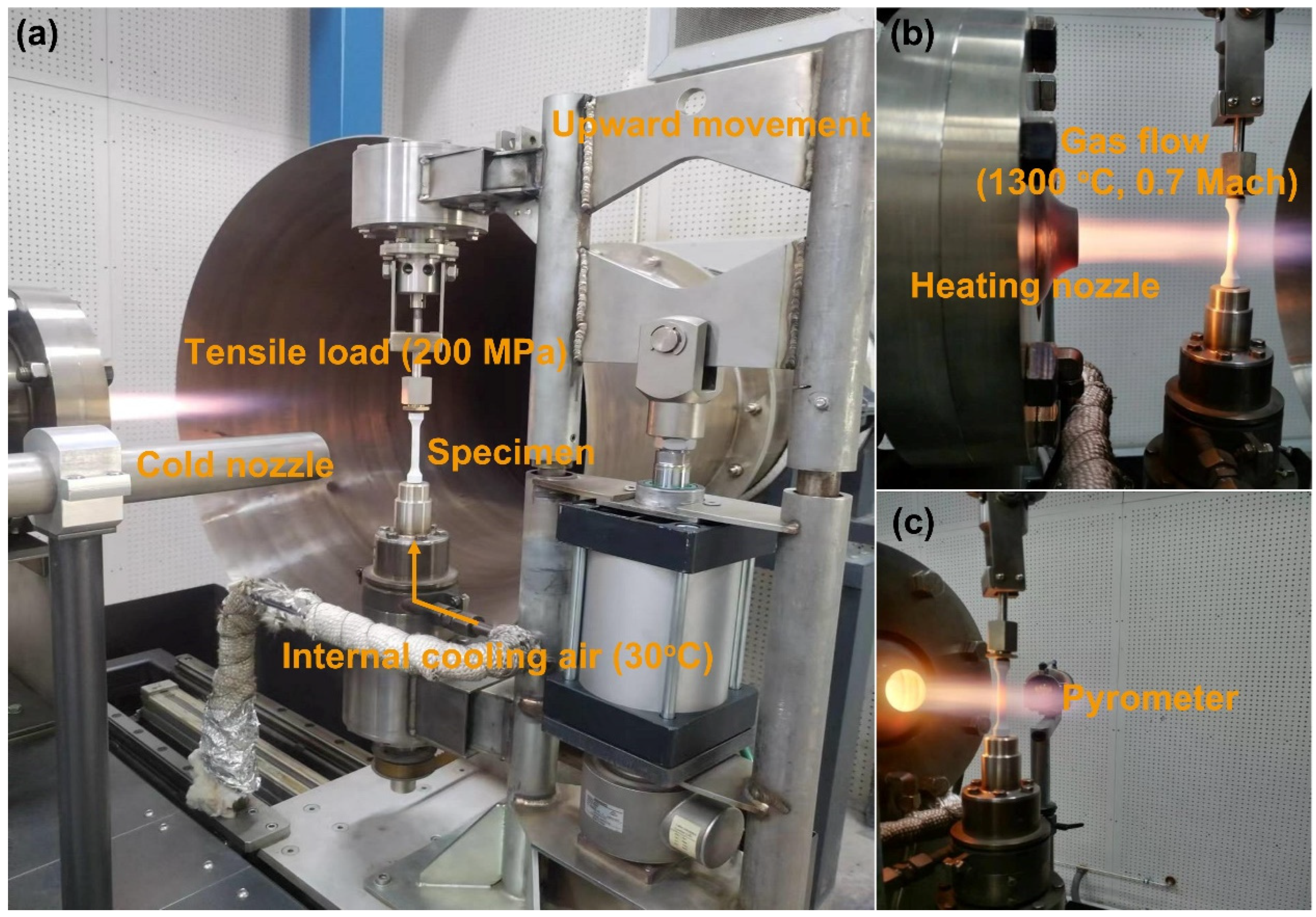
2.2. Thermo-Mechanical Coupling Testing with Temperature Gradient

The thermo-mechanical coupling test with temperature gradient (TMTG) was carried out using multifactor coupling equipment (MK Technology GmbH, BTR-MK, Germany). The test simulated the centrifugal force during blade rotation by applying an axial tension on the rod specimen. In this study, an axial load of 3454 N (corresponding to a nominal stress of 200 MPa) was employed according to the centrifugal stress in the middle of the high-pressure turbine blade of a certain type of engine. A load-controlled mode was chosen because of the thermal heterogeneity in the specimens [17].
Figure 1 shows the experimental setup. The gas injection speed was 0.7 Mach to achieve a gas temperature (Tg) of 1300 °C, and room temperature cooling air with a mass flow rate of 1 g/s was introduced into the round tube to establish a temperature gradient along the TBC thickness direction. The topcoat surface temperature (Tsurf) was evaluated using an optical pyrometer with a measurable wavelength range of 9.6–11.5 μm (Infrared Messtechnik GmbH, KT15 II Serie, Germany) (Figure 1c). A detailed measurement of the emissivity of YSZ coating can be found in Appendix B. The Tsurf was maintained at 1130 °C during the test. The substrate temperature (Tsub) was measured as 1070 °C by drilling a hole in the wall of the hollow specimen and inserting a thermocouple (Figure 2b).
The profile of temperature and mechanical loading during a TMTG process is shown in Figure 2b; each cycle consisted of three stages of heating, dwelling, and cooling. The cycle started at 30 °C, followed by a heating period of 15 s until a dwell temperature of 1130 °C was reached (corresponding to a heating rate of ~73.3 °C/s). The dwelling time of each cycle was ~55 min. After that, the specimen holder changed rapidly to the cooling position, in which the specimens cooled rapidly by forced convection from the cold air nozzle (Figure 1a). The coating surface temperature reduced to 30 °C after 1 min of cooling (corresponding to a cooling rate of ~18.3 °C/s). During the cycling, the axial tensile load was applied throughout the heating and cooling process. Thermo-mechanical cycles of 0, 20, 45, and 70 times were conducted, and an extra specimen that underwent 70 thermal cycles (without tensile load) was used for the comparison. The thermo-mechanical tests were stopped overnight for safety reasons, and the specimens were carefully examined for damage before and after every test.

2.3. Microstructure Characterization

After the thermo-mechanical coupling test, the rod specimens were cross-sectioned using a SiC abrasive cutting blade for the following microstructure’s characterization. All the specimens for the scanning electron microscope (SEM, Rise, TESCAN, Brno, Czech) were prepared using a standard metallographic procedure; the ring-shaped TBCs were vacuum-impregnated by epoxy (EpoFix, Struers, Ballerup, Denmark) and then subjected to grinding (with SiC papers up to 3000 grit) and polishing (with 50 nm alumina suspension). Backscatter electron (BSE) images were taken because they can exhibit higher compositional contrast. Chemical composition analysis was performed by using energy dispersive spectroscopy (EDS, Aztec X-MaxN80, Oxford, UK) equipped in the SEM. For the interface morphology, the X-ray microscope (XRM, Xradia 520 Versa, Carl Zeiss, Wetzlar, Germany) was utilized. Before scanning, the specimens were carefully cut down to ~1 mm (by diamond wire cutting with coolant) to increase the X-ray transmission. The operation energy was set at 160 kV for all the scans. Each scan comprises 3001 projections equi-angularly distributed over 360° specimen rotation. The reconstructed virtual slices have a voxel size of 1 μm. Three-dimensional (3D) image analysis including filtering and shaping was conducted in ORS Dragonfly software (4.0, Carl Zeiss, Wetzlar, Germany). Two-dimensional (2D) slices were then exported for further image processing. The topcoat/TGO interfacial contour in the 2D images were extracted using imageJ software (1.46r) through image processing functions, including binary, watershed, and particle analysis.

3. Results

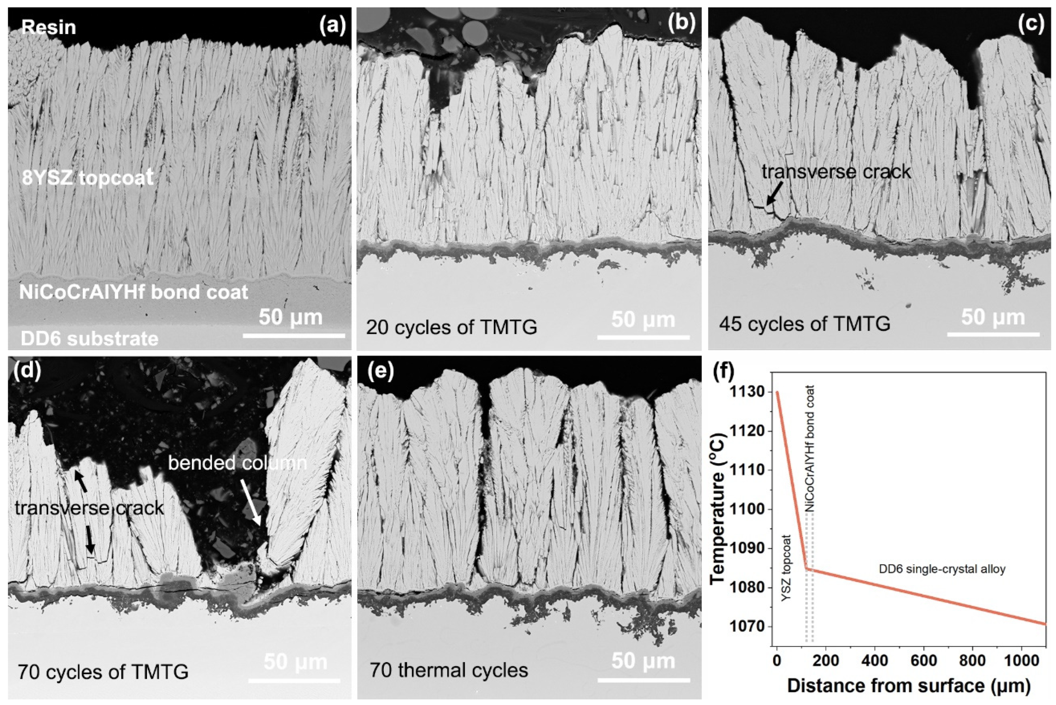
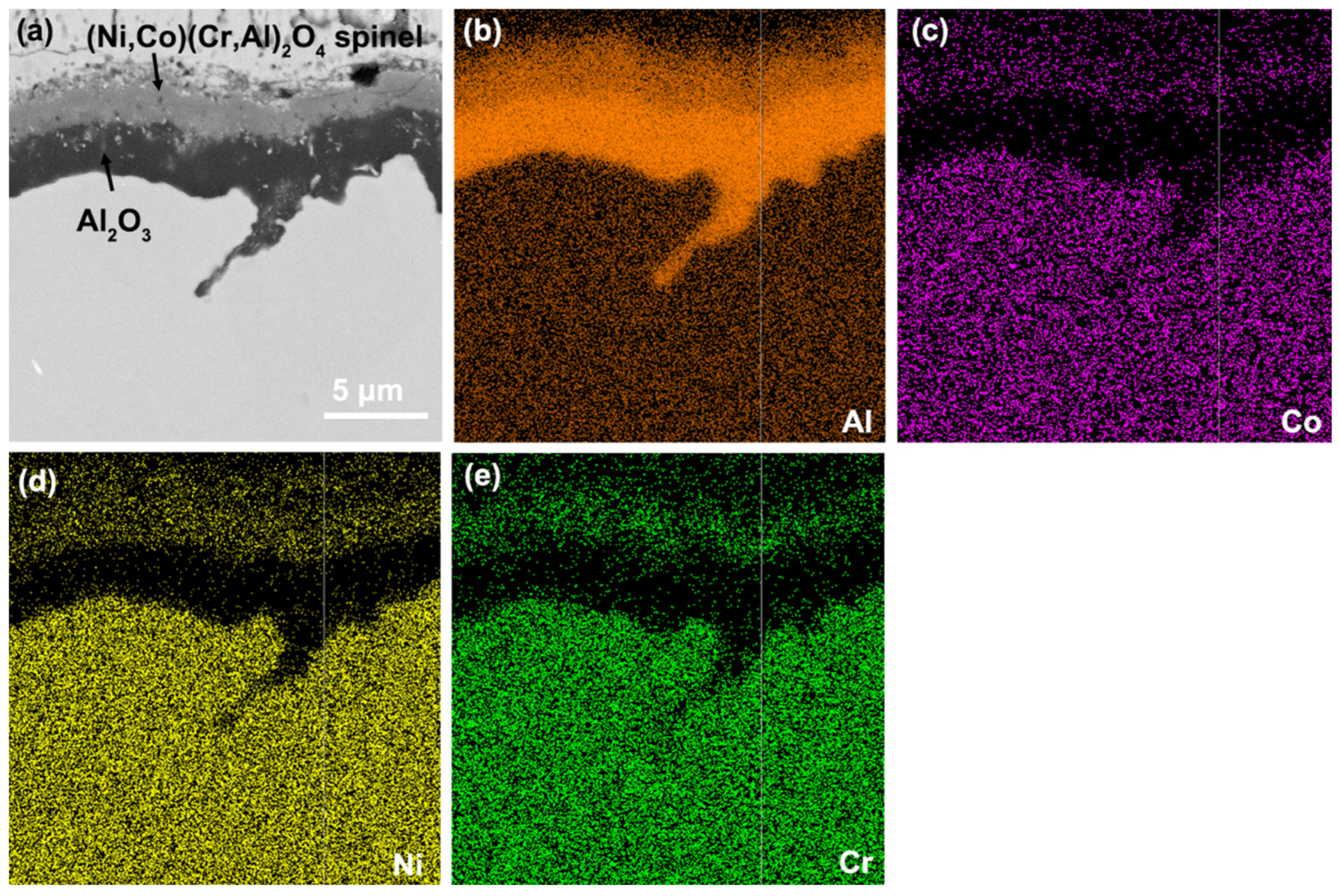
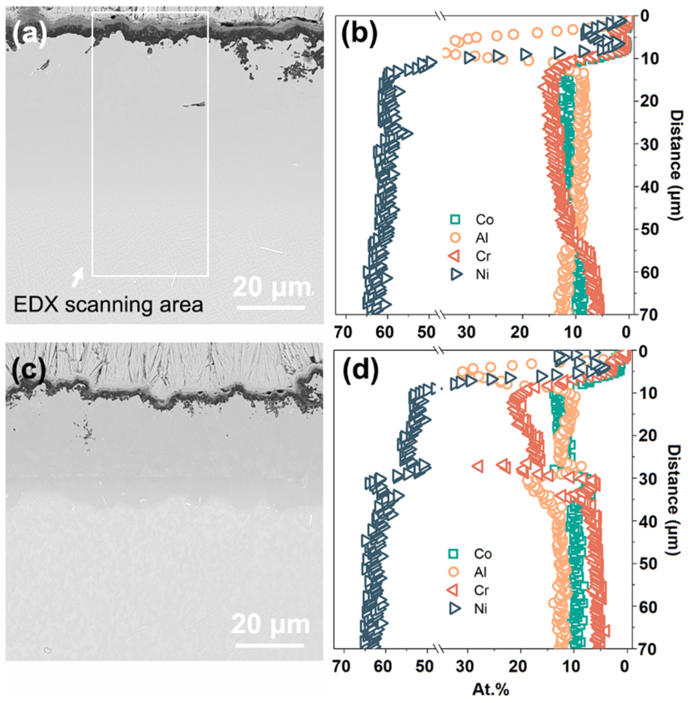
3.1. Microstructure and Composition of the TBCs after TMTG Cycles

The circumferential cross-sections of TBCs before and after the TMTG cycles are shown in Figure 3a–d; the specimen that underwent thermal cycling without tensile load is shown in Figure 3e. It can be seen that some fragments appear at the tip of columnar grains after 20 cycles of thermo-mechanical tests (Figure 3b). After 45 cycles, intergranular cracking of the topcoat occurs (Figure 3c), and after 70 cycles, delamination of the TBC is observed, and the fracture of columnar grains is more severe (Figure 3d). Bending of the YSZ columns to the right of the delaminated region is also visible (indicated in Figure 3d), which implies that the columns are undergoing plastic deformation during the thermo-mechanical test. When no mechanical load is applied (Figure 3e), the TBCs remain almost intact and only an increase in the column gap is observed. The temperature gradient of TBCs facing the flame during a dwelling stage is shown in Figure 3f, with a one-dimensional heat flux approximation ( q i = k i · Δ T i / L i , heat flux q, thermal conductivity k, temperature drop ΔT, and layer thickness L) being applied [23]. The bond coat temperature is found to be ~1084 °C. Thermal conductivity values were obtained from Ref. [24]; fixed approximate values of 1 W/m/K, 31.6 W/m/K, and 26 W/m/K were taken for the topcoat, the bond coat, and the substrate, respectively.
Beneath the topcoat, a double-layered TGO is formed in all the specimens. The enlarged BSE image and the corresponding elemental mappings in Figure 4 suggest that the upper layer is spinel oxides enriched with Ni, Cr, and Co and the bottom layer is alumina. Usually, the spinel on MCrAlY coatings can form in two different ways. On the one hand, the spinel could form at the very early stage of oxidation where the base mental elements have a preference over Al. On the other hand, formation of the spinel could also occur after the establishment of a continuous α-Al2O3 until the depletion of Al in the bond coat. This issue might be clarified from the microstructure of the TGO layer. Instead of discontinuous fragments embedded in alumina, a common feature of spinel grown in the early stage [21], the spinel layers in Figure 3 are continuous. Moreover, the interfacial temperature (1084 °C) is sufficient for the Al oxidation, and the Gibbs free energy of the formation of Al2O3 (−850.5 KJ/mol @1000 °C) is lower than that of other oxides, e.g., NiCr2O4 (−42.9 KJ/mol@1000 °C), etc. These two points mean that the spinel is more likely to be formed after a continuous α-Al2O3 is established.
Figure 5 shows the microstructure and chemical composition of TBCs after 20 cycles of TMTG. The front and back sides of the gauge region (cylindrical central part of the sample, i.e., areas facing and facing away from the heating nozzle) have been compared. Both the areas are double-layered TGO; the spinel and the alumina thickness on the back side are smaller than that facing the flame because there is a temperature difference of ~150 °C. Elemental profiles perpendicular to the interface were acquired by conducting area scans according to Figure 5a and averaging the horizontal values. It can be found that the Cr and Al content in the bond coat on the back side is higher, while its Ni content is lower. This also indicates that TGO growth consumes Cr, Al, and Ni, of which Ni diffuses from the substrate to the bond coat with oxidation lasts.
It should be noted that the fatigue cracks or voids, which are the common defects in the thermo-mechanical fatigue tests [15,25,26], are not observed in the bond coat of all the specimens in this work. The tensile loads were still applied to the TBCs during and after the cooling to room temperature, and although the brittleness of bond coat increases below the ductile–brittle transition temperature, the sustained applied mechanical load is not sufficient to crack it within the thermal cycles performed.

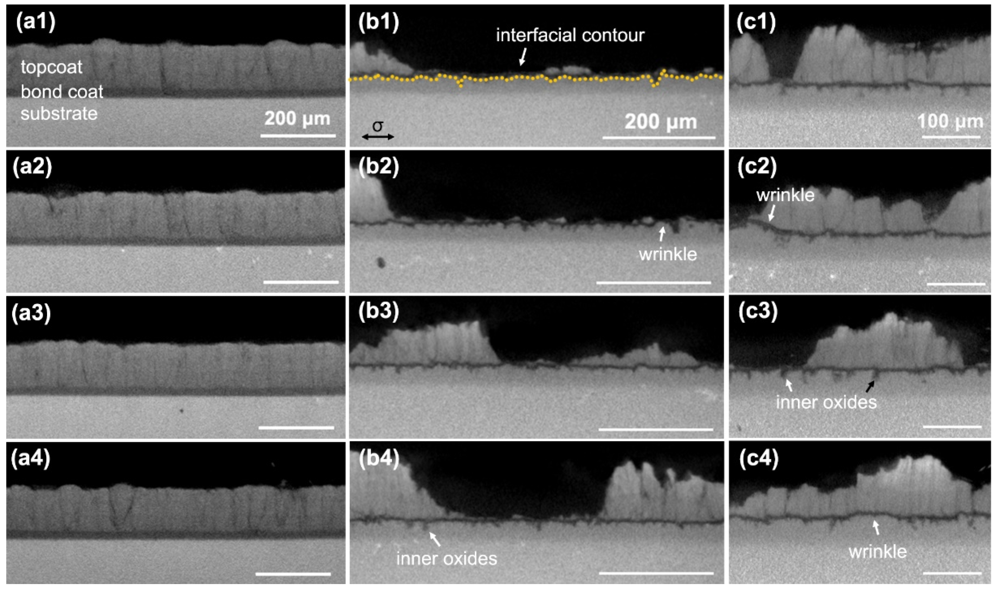
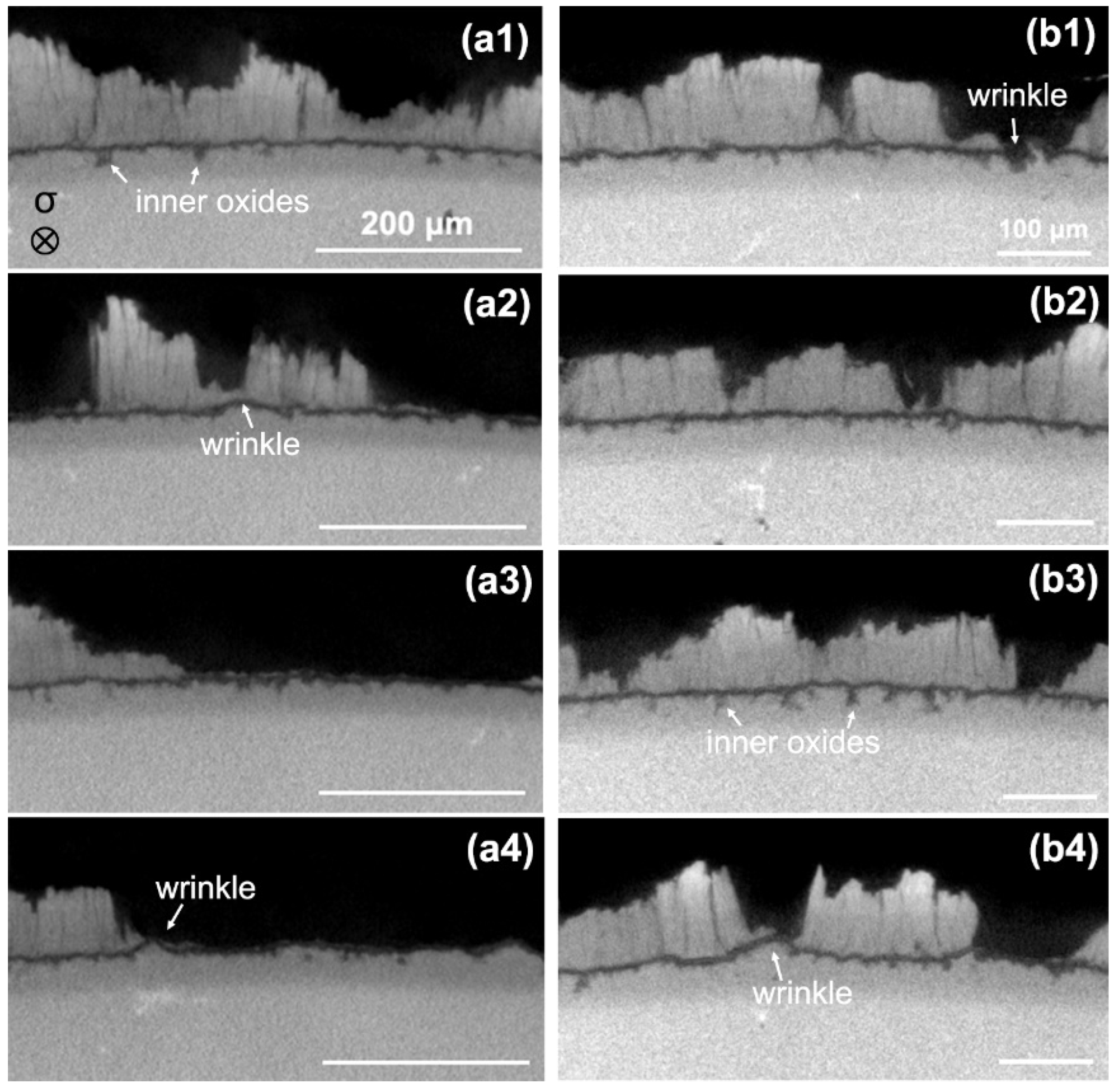
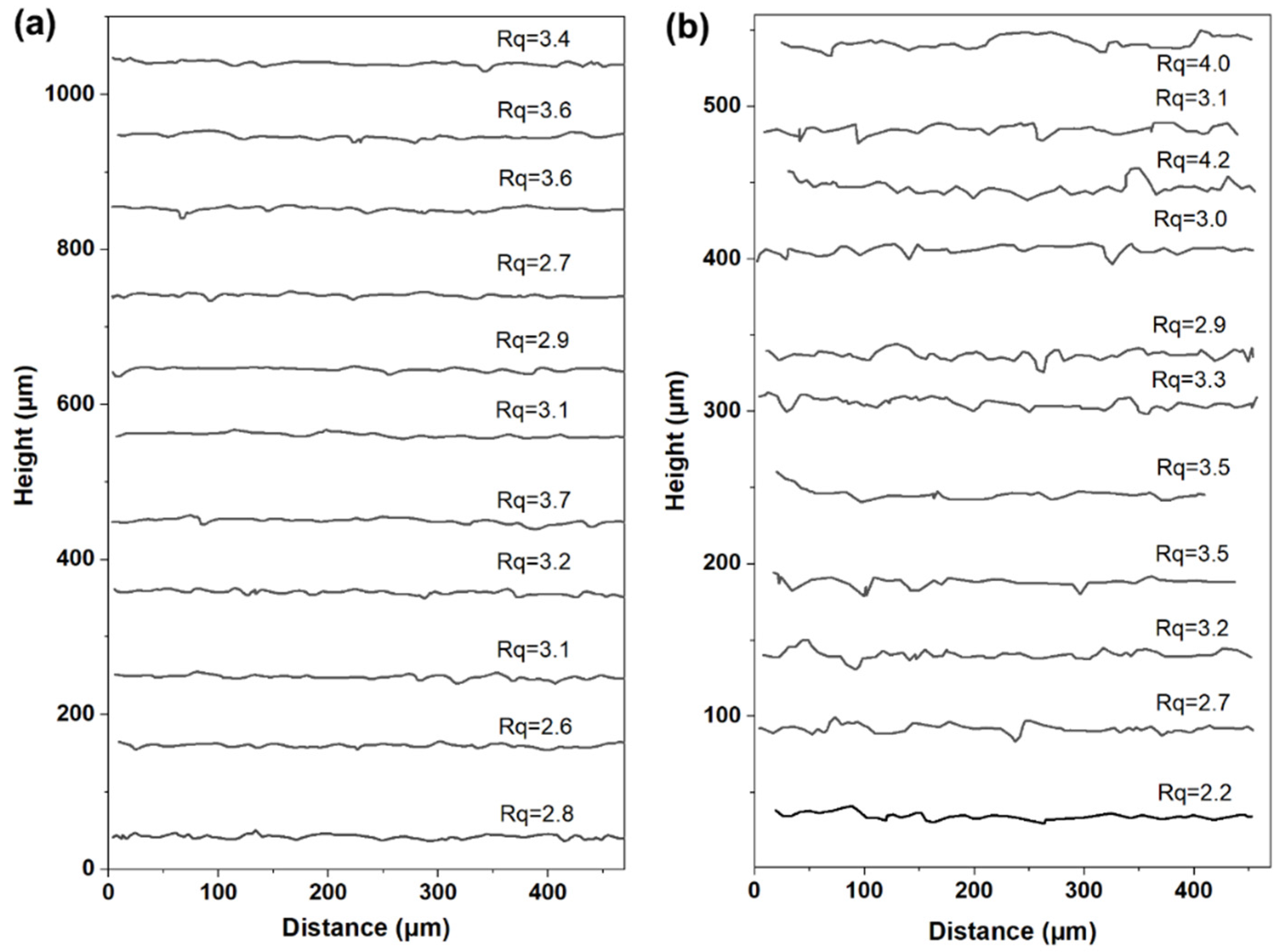
3.2. Interfacial Morphology of the TBCs after TMTG Cycles

As demonstrated by the SEM images in Figure 3, the failure of TBCs under the cyclic thermo-mechanical with thermal gradient occurred at the TGO/bond coat interface, as commonly observed for EB-PVD TBC systems. However, the spallation of the specimen that has undergone the cyclic thermo-mechanical test is obviously severer than the specimen that has not been mechanically loaded. Figure 6 is the 3D views of TBCs measured by XRM; the specimens were taken from the area close to the flame center. Due to the limitation of cutting equipment, the specimen’s geometry was not exactly the same. The mechanical loading is marked in Figure 6b,c to gain an intuitive perspective. The 3D views evidenced that the as-prepared TBCs are integrated; however, after 70 cycles of TMTG, there is spallation to a certain extent, and the residual columns are broken. The spallation of TBCs after 70 thermal cycles without tensile loading is obviously reduced.
Figure 7 and Figure 8 show the 2D virtual μ-CT slices of the axial and tangential cross-section on the cylinder (i.e., parallel and perpendicular to the mechanical loading), respectively. The interface between the topcoat and bond coat of the as-prepared TBCs is rather smooth (Figure 7(a1–a4)), while plenty of wrinkles are formed after thermal exposure. The topcoat/TGO interfacial contour were extracted from the μ-CT slices using imageJ software through image processing functions, including binary, watershed, and particle analysis. This image processing allows us to obtain the coordinates of each point on the contour. A total of 11 slices were randomly selected from each scan of the specimen, and the same image processing was carried out. The extracted interfacial contours of the cross-section parallel to the mechanical loading are plotted in Figure 9, and the interfacial roughness is calculated accordingly. Although the XRM scan range is different for different specimens, a similar sampling length of ~500 μm is used for the data plot and the data math. The mean square root roughness, Rq, is defined as follows [27]:
R q = 1 n i = 1 n y i y ¯ 2
where n is the total number of coordinate data; y ¯ is the average value of vertical coordinates, y. For TBCs after 70 cycles of TMTG, Rq = 3.15 ± 0.38 μm; for TBCs after 70 thermal cycles (without tensile loading), Rq = 3.24 ± 0.57 μm. There is no statistically significant difference between the Rq of these two, but the average value and the dispersion degree of the TMTG specimen are smaller.
For the interfacial roughness of the cross-section perpendicular to the mechanical loading (as plotted in Figure 10), Equation (1) is no longer applicable since the baseline is not a straight line but an arc (corresponding to the cylindrical surface). Therefore, the arc is used to fit the tangential interface by use of the least square method, and the roughness of the tangential interface is then defined as the root mean square deviation of the interfacial contour relative to the baseline. The detailed Python code used for this calculation can be found in Appendix C.
The roughness calculated according to Figure 10 shows that the tangential interface roughness of the TBCs after TMTG is larger than that of the TBCs after thermal cycling without tensile loading. It should be noted that due to the difference in baseline, the longitudinal and tangential interfacial roughness cannot be used for comparison. However, using the thermal-cycled TBCs without tensile loading as a reference, it can be inferred that an anisotropic TGO/bond coat rumpling is developed after TMTG cycling.
The mechanisms that govern the surface roughening (also termed as rumpling, ratcheting, or undulation) can be complicated [18,28,29,30,31]. It has been generally accepted that the stress in TGO, either from the lateral growth or the thermal mismatch, is the primary driving force for the rumpling at the TGO/bond coat interface. The in-plane compression of TGO arises with its lateral growth [32]; for mechanical equilibrium, compressive stress in the oxide must be balanced by tensile stress in the conterminous bond coat. Rumpling, which is a mechanism for the relaxation of elastic strain energy, requires the plastic deformation of TGO and the bond coat. Yang et al. [33] developed an analytical model to evaluate the high-temperature stress in the bond coat, and the critical stress required to active the diffusional creep of the NiCoCrAlY bond coat is identified as 0.5 MPa (i.e., the minimum stress to active the grain sliding). Not only does creep contribute to the plastic strain but yielding also leads to deformation. The yielding strength of the NiCoCrAlY bond coat is dramatically reduced with the increasing temperature (less than 50 MPa at 1000 °C [34]).
Young’s modulus of the NiCoCrAlYHf bond coat is close to that of the DD6 substrate [35,36]. As the substrate is much thicker than the other layers combined (approximately seven times), the strain resulting from the applied load is dominated by the substrate; it can be deduced that the bond coat has a similar stress value of ~200 MPa with the substrate. Therefore, the plastic deformation of the bond coat is inevitable.

4. Discussion

Failure Analysis of the TBCs in Thermo-Mechanical Loading with Temperature Gradient

The spallation in the thermo-mechanical specimens is significantly enhanced compared with the thermal cycling without tensile loads; moreover, in both tests, the YSZ topcoat separates from TGO, and the oxide scales remain in contact with the bond coat surface. Tzimas et al. [10] studied the thermo-mechanical fatigue with high (~0.65%) and low (0.4%) mechanical strain, and the cracking of the bond coat was absent under the lower mechanical strain. Here, the mechanical strain during a dwelling period is estimated to be ~0.26% (take the elastic modulus in the [001] direction of DD6 substrate as 78.1 GPa at 1000 °C [36]); the relatively low strain level might be the reason for the absence of bond coat cracking or voids.
The stress in TGO is the primary driving force for the rumpling at the TGO/bond coat interface; it has two contributions, lateral growth stress and thermal mismatch stress. The lateral growth of TGO (mainly occurs at the dwelling stage) produces compressive stress in the growing oxide [37,38] in both the longitudinal and tangential direction. Clarke [32] developed a dislocation climb model for growth strain and, accordingly, compressive stress of an order of 0.5–1.5 GPa is generated by high-temperature oxidation.
The temperature gradient is mainly concentrated in the YSZ topcoat; however, the discontinuous columnar structure by the EB-PVD technique allows the substrate to exert limited constraint on its thermal expansion and vice versa. On the other hand, although the temperature gradient across the TGO/bond coat/substrate is rather small (~14 °C, Figure 3f), the difference in the coefficient of thermal expansion (CTE) between TGO and the substrate is ~7 × 10⁻⁶/°C (as listed in Table 2), inducing thermal mismatch stress in TGO by the following:
σ = E Δ T Δ α 1 ν 2
where E and ν are the elastic modulus and the Poisson ratio of TGO, respectively; ΔT and Δα are the temperature variation and the CTE mismatch between TGO and substrate, respectively. The direction of thermal mismatch stress depends on the stress-free temperature, and it is generally assumed that the deposition temperature is the reference temperature (900 °C here). A tensile stress of ~0.43 GPa is then generated in TGO by thermal mismatch during the dwelling stage with a temperature variation of 180 °C (heat up to the interface temperature in Figure 3f). Like growth stress, thermal mismatch stress also exists in both the longitudinal and tangential direction.
The externally applied axial load gives only longitudinal stress; therefore, in the dwelling stage, in the longitudinal direction, TGO is subjected to the tensile mechanical loads, compressive growth stress, and tensile thermal mismatch stress, while in the tangential direction, TGO is subjected to the latter two. That is, the compressive stress is greater in the tangential direction, which leads to anisotropic rumpling of the interfacial rumpling. This anisotropic rumpling caused by uniaxial stress had been evidenced in the (Ni,Pt)Al/CMSX-4 system as well [27,39].
Table 2. Thermophysical properties of the TBCs.
α (×10−6/°C)E (GPa)ν
TGO (α-Al2O3)5.08–9.20 [40]309–380 [40]0.27 [40]
NiCoCrAlYHf12.3–17.6 [40]72–152 [40]0.32–0.35 [40]
DD611.9–15.0 [36]78.1–131 [36]0.34–0.39 [36]
The strain within multilayered TBCs needs to be consistent; with an increased interfacial rumpling, the strain compliance between the topcoat and TGO intensifies the shear stress between the two and affects the out-of-plane stress redistribution. Aleksanoglu et al. [14] conducted a FE analysis of the stress distribution during the thermo-mechanical test with a thermal gradient, and the results of the radial stress showed that in the peak region of the topcoat/TGO interface, tensile stress for the bond coat and TGO occurred, as well as Tzimas et al.’s [10] failure analysis of TBCs under cyclic thermo-mechanical loading. The superposition of mechanical strains enhances the local tensile stress perpendicular to the interface, which is supposed to facilitate the coating delamination [14]. In addition to the interior spallation, a large number of column breaks has been observed. The fast cooling of the topcoat surface results in transient tensile stress; while the bottom of the topcoat still remains in compression, the shear within the topcoat is supposed to promote the formation of transverse cracks which break the column in half [8,23]. Detailed modeling of combined oxide growth and mechanical loading for the NiCoCrAlYHf/DD6 system will be investigated in the future.

5. Conclusions

This study has investigated the failure of TBCs under cyclic thermo-mechanical loading with thermal gradient. In light of the results obtained, the main findings are highlighted below:
(1)
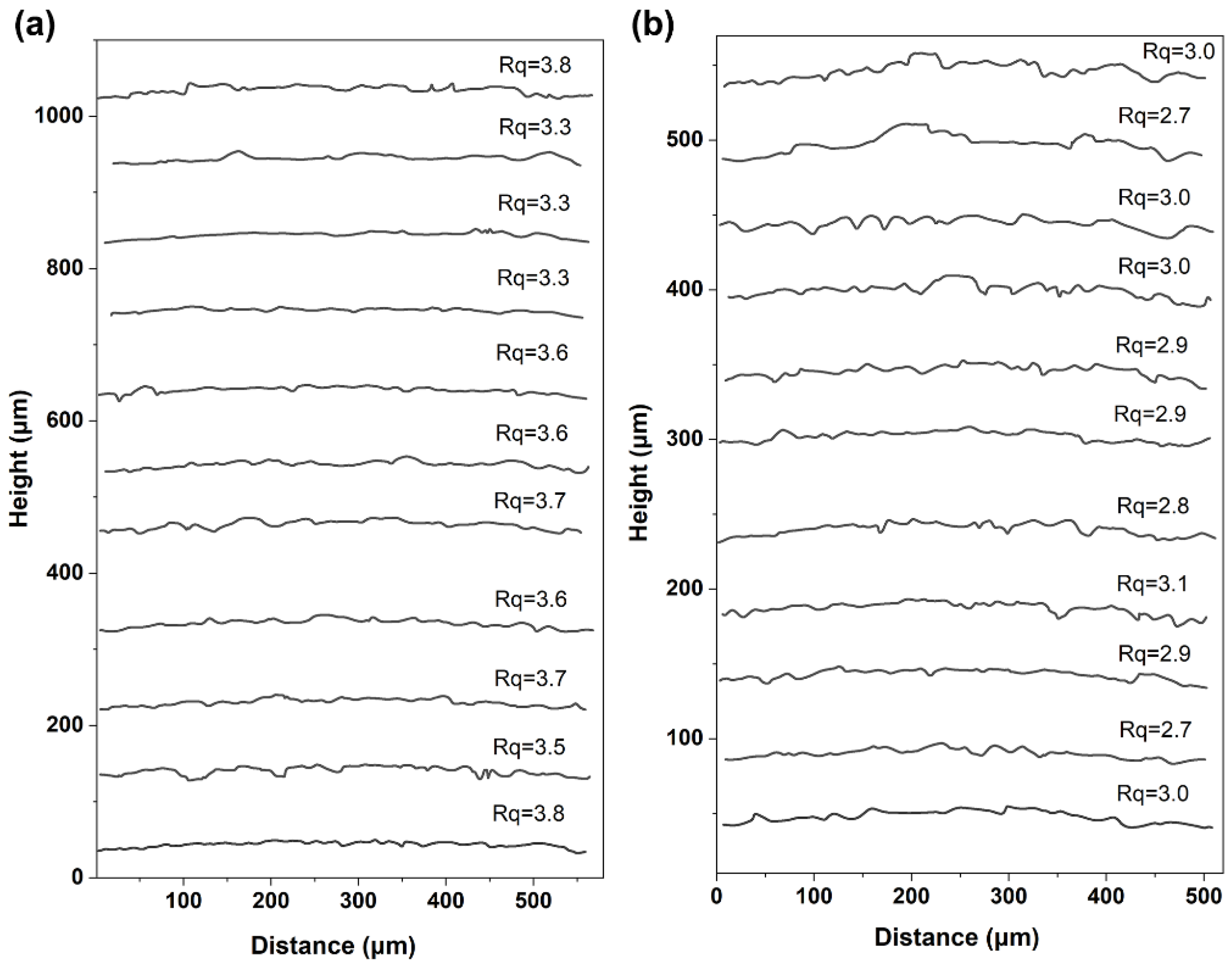
The uniaxial tensile loading results in anisotropic rumpling. Compared with thermal cycles without mechanical loads, the TMTG specimens exhibit an enhanced TGO/bond coat interface on the tangential cross-section.
(2)
TGO exhibits a duplex microstructure, consisting of outer spinel and inner α-Al2O3. The mechanical load has little effect on the configuration of TGO, and the temperature only affects the TGO’s thickness, not its structure.
(3)
The mechanical strain has effectively accelerated the spallation of TBCs; it is inferred that the superposition of mechanical strain enhances the local tensile stress at the peak region of the topcoat/TGO interface. Quantification of the thermo-mechanical loading-induced rumpling effect needs further computational investigations.

Author Contributions

Conceptualization, L.L. and D.L.; methodology, D.L.; software, W.Y.; validation, R.M., L.H. and H.C.; data curation, L.L.; writing—original draft preparation, L.L. and D.L.; writing—review and editing, L.L. and H.C.; supervision, H.C. All authors have read and agreed to the published version of the manuscript.

Funding

This work is supported by the National Science and Technology Major Project (J2019-IV-0003-0070). The funding support of this research work by project of KJSJ220543 is also gratefully acknowledged.

Institutional Review Board Statement

Not applicable.

Informed Consent Statement

Not applicable.

Data Availability Statement

The data presented in this study are available on request from the corresponding author.

Conflicts of Interest

The authors declare no conflicts of interest.

Appendix A

Figure A1. CAD drawing of the DD6 single-crystal superalloy for thermo-mechanical coupling test.
Coatings 14 00902 g0a1

Appendix B

Although the optical pyrometer allows one to realize experiments in contactless mode at temperatures exceeding 2000 °C, this measurement principle is highly sensitive to deviations in the emissivity characteristics of the specimen that must be precisely known in advance. First, a B-type thermocouple was positioned in contact with the YSZ coating surface. The equipment was then run by selecting the operating point with a Tg of 1300 °C. Once the device reached stability during operation, the temperatures measured by the optical pyrometer and the thermocouple approached each other, providing an emissivity value of 0.33.

Appendix C

Python code for the tangential interface roughness.
diameter_mm = 6.5
radius_mm = diameter_mm/2
r_data = radius_mm
theta_data = np.arcsin(x_data/radius_mm)
def circle_func(theta, r_fit, theta_fit):
return r_fit * np.cos(theta − theta_fit)
popt, pcov = curve_fit(circle_func, theta_data, r_data, p0 = [radius_mm, 0])
r_fit = popt [0]
theta_fit = popt [1]
rmse = np.sqrt(np.mean((circle_func(theta_data, *popt) − r_data)**2))
theta_standard = np.linspace(0, 2*np.pi, 100)
r_standard = np.ones_like(theta_standard) * radius_mm
r_fit_circle = np.ones_like(theta_standard) * r_fit
fig, ax = plt.subplots(subplot_kw = {‘projection’: ‘polar’}, figsize = (8, 8))
Figure A2. Mapping points and fitted circular of the tangential interfacial contour.
Coatings 14 00902 g0a2

References

  1. Cao, X. Application of Rare Earths in Thermal Barrier Coating Materials. J. Mater. Sci. Technol. 2007, 23, 15–35. [Google Scholar]
  2. Beele, W.; Marijnissen, G.; van Lieshout, A. The evolution of thermal barrier coatings—status and upcoming solutions for today’s key issues. Surf. Coat. Technol. 1999, 120–121, 61–67. [Google Scholar] [CrossRef]
  3. Zhen, Z.; Wang, X.; Shen, Z.; Mu, R.; He, L.; Xu, Z. Thermal cycling behavior of EB-PVD rare earth oxides co-doping ZrO2-based thermal barrier coatings. Ceram. Int. 2021, 47, 23101–23109. [Google Scholar] [CrossRef]
  4. Bedoya-Trujillo, I.F.; Pérez, S.; Guijosa-García, C.Y.; Rivera-Gil, M.A.; Naraparaju, R.; Zárate-Medina, J.; Muñoz-Saldaña, J. Evaluation of the reactivity of dense lanthanum-gadolinium zirconate ceramics with Colima volcanic ashes. Surf. Coat. Technol. 2023, 470, 129825. [Google Scholar] [CrossRef]
  5. Sivakumar, R.; Mordike, B.L. High temperature coatings for gas turbine blades: A review. Surf. Coat. Technol. 1989, 37, 139–160. [Google Scholar] [CrossRef]
  6. Dai, J.; Huang, B.; He, L.; Mu, R.; Tian, H.; Xu, Z. Thermal cycling behavior and failure mechanism of Yb2O3-doped yttria-stabilized zirconia thermal barrier coatings. Mater. Today Commun. 2023, 34, 105409. [Google Scholar] [CrossRef]
  7. Li, C.-J.; Dong, H.; Ding, H.; Yang, G.-J.; Li, C.-X. The Correlation of the TBC Lifetimes in Burner Cycling Test with Thermal Gradient and Furnace Isothermal Cycling Test by TGO Effects. J. Therm. Spray. Technol. 2017, 26, 378–387. [Google Scholar] [CrossRef]
  8. Vaßen, R.; Bakan, E.; Mack, D.; Schwartz-Lückge, S.; Sebold, D.; Jung Sohn, Y.; Zhou, D.; Guillon, O. Performance of YSZ and Gd2Zr2O7/YSZ double layer thermal barrier coatings in burner rig tests. J. Eur. Ceram. Soc. 2020, 40, 480–490. [Google Scholar] [CrossRef]
  9. Vaßen, R.; Cernuschi, F.; Rizzi, G.; Scrivani, A.; Markocsan, N.; Östergren, L.; Kloosterman, A.; Mevrel, R.; Feist, J.; Nicholls, J. Recent Activities in the Field of Thermal Barrier Coatings Including Burner Rig Testing in the European Union. Adv. Eng. Mater. 2008, 10, 907–921. [Google Scholar] [CrossRef]
  10. Tzimas, E.; Müllejans, H.; Peteves, S.D.; Bressers, J.; Stamm, W. Failure of thermal barrier coating systems under cyclic thermomechanical loading. Acta Mater. 2000, 48, 4699–4707. [Google Scholar] [CrossRef]
  11. Kitazawa, R.; Tanaka, M.; Kagawa, Y.; Liu, Y.F. Damage evolution of TBC system under in-phase thermo-mechanical tests. Mater. Sci. Eng. B 2010, 173, 130–134. [Google Scholar] [CrossRef]
  12. Bartsch, M.; Baufeld, B.; Dalkilic, S.; Chernova, L.; Heinzelmann, M. Fatigue cracks in a thermal barrier coating system on a superalloy in multiaxial thermomechanical testing. Int. J. Fatigue 2008, 30, 211–218. [Google Scholar] [CrossRef]
  13. Peichl, A.; Beck, T.; Vöhringer, O. Behaviour of an EB-PVD thermal barrier coating system under thermal–mechanical fatigue loading. Surf. Coat. Technol. 2003, 162, 113–118. [Google Scholar] [CrossRef]
  14. Aleksanoglu, H.; Scholz, A.; Oechsner, M.; Berger, C.; Rudolphi, M.; Schütze, M.; Stamm, W. Determining a critical strain for APS thermal barrier coatings under service relevant loading conditions. Int. J. Fatigue 2013, 53, 40–48. [Google Scholar] [CrossRef]
  15. Baufeld, B.; Tzimas, E.; Hähner, P.; Müllejans, H.; Peteves, S.D.; Moretto, P. Phase-angle effects on damage mechanisms of thermal barrier coatings under thermomechanical fatigue. Scr. Mater. 2001, 45, 859–865. [Google Scholar] [CrossRef]
  16. Baufeld, B.; Bartsch, M.; Heinzelmann, M. Advanced thermal gradient mechanical fatigue testing of CMSX-4 with an oxidation protection coating. Int. J. Fatigue 2008, 30, 219–225. [Google Scholar] [CrossRef]
  17. Mauget, F.; Hamon, F.; Morisset, M.; Cormier, J.; Riallant, F.; Mendez, J. Damage mechanisms in an EB-PVD thermal barrier coating system during TMF and TGMF testing conditions under combustion environment. Int. J. Fatigue 2017, 99, 225–234. [Google Scholar] [CrossRef]
  18. Shi, J.; Karlsson, A.M.; Baufeld, B.; Bartsch, M. Evolution of surface morphology of thermo-mechanically cycled NiCoCrAlY bond coats. Mater. Sci. Eng. A 2006, 434, 39–52. [Google Scholar] [CrossRef]
  19. Li, J.R.; Zhong, Z.G.; Tang, D.Z.; Liu, S.Z.; Wei, P.; Wei, P.Y.; Wu, Z.T.; Huang, D.; Han, M. A low-cost second generation single crystal superalloy DD6. In Superalloys 2000: Proceedings of the Ninth International Symposium on Superalloys; Pollock, T.M., Kissinger, R.D., Bowman, R.R., Green, K.A., McLean, M., Olson, S., Schirra, J.J., Eds.; TMS: Knoxville, TN, USA, 2000; pp. 777–783. [Google Scholar]
  20. Liu, D.; Li, J.; Jin, X.; Mu, R.; Yang, W. Effect of Coating Pre-Treatment on Surface Recrystallization of DD6 Single Crystal. Materials 2022, 15, 7004. [Google Scholar] [CrossRef]
  21. Liu, X.; Chen, Y.; Li, L.; Huang, A.; Zhang, H.; Zhang, X.; Lu, J.; Zhao, X. On the oxidation and interdiffusion behavior of an AlCoCrFeNiY high-entropy alloy bond coat on a directionally solidified Ni-based superalloy. J. Mater. Sci. Technol. 2024, 186, 64–78. [Google Scholar] [CrossRef]
  22. Liu, D.; Cai, H.; Mu, R.; Yang, W.; Dong, J. Effect of grit-blasting on the recrystallization behavior of DD6 single-crystal superalloy coated with NiCoCrAlYHf. J. Alloys Compd. 2024, 983, 173861. [Google Scholar] [CrossRef]
  23. Vaßen, R.; Mack, D.E.; Tandler, M.; Sohn, Y.J.; Sebold, D.; Guillon, O. Unique performance of thermal barrier coatings made of yttria-stabilized zirconia at extreme temperatures (>1500 °C). J. Am. Ceram. Soc. 2020, 104, 463–471. [Google Scholar] [CrossRef]
  24. Vaßen, R.; Giesen, S.; Stöver, D. Lifetime of Plasma-Sprayed Thermal Barrier Coatings: Comparison of Numerical and Experimental Results. J. Therm. Spray Technol. 2009, 18, 835–845. [Google Scholar] [CrossRef]
  25. Vaßen, R.; Kagawa, Y.; Subramanian, R.; Zombo, P.; Zhu, D. Testing and evaluation of thermal-barrier coatings. MRS Bull. 2012, 37, 911–916. [Google Scholar] [CrossRef]
  26. Tanaka, M.; Mercer, C.; Kagawa, Y.; Evans, A.G. Thermomechanical Fatigue Damage Evolution in a Superalloy/Thermal Barrier System Containing a Circular Through Hole. J. Am. Ceram. Soc. 2011, 94, s128–s135. [Google Scholar] [CrossRef]
  27. Dryepondt, S.; Porter, J.R.; Clarke, D.R. On the initiation of cyclic oxidation-induced rumpling of platinum-modified nickel aluminide coatings. Acta Mater. 2009, 57, 1717–1723. [Google Scholar] [CrossRef]
  28. Balint, D.S.; Kim, S.S.; Liu, Y.-F.; Kitazawa, R.; Kagawa, Y.; Evans, A.G. Anisotropic TGO rumpling in EB-PVD thermal barrier coatings under in-phase thermomechanical loading. Acta Mater. 2011, 59, 2544–2555. [Google Scholar] [CrossRef]
  29. Karlsson, A.M.; Levi, C.G.; Evans, A.G. A model study of displacement instabilities during cyclic oxidation. Acta Mater. 2002, 50, 1263–1273. [Google Scholar] [CrossRef]
  30. Balint, D.; Hutchinson, J. An analytical model of rumpling in thermal barrier coatings. J. Mech. Phys. Solids 2005, 53, 949–973. [Google Scholar] [CrossRef]
  31. Chen, Y.; Zhao, X.; Bai, M.; Yang, L.; Li, C.; Wang, L.; Carr, J.A.; Xiao, P. A mechanistic understanding on rumpling of a NiCoCrAlY bond coat for thermal barrier coating applications. Acta Mater. 2017, 128, 31–42. [Google Scholar] [CrossRef]
  32. Clarke, D.R. The lateral growth strain accompanying the formation of a thermally grown oxide. Acta Mater. 2003, 51, 1393–1407. [Google Scholar] [CrossRef]
  33. Yang, L.; Zou, Z.; Kou, Z.; Chen, Y.; Zhao, G.; Zhao, X.; Guo, F.; Xiao, P. High temperature stress and its influence on surface rumpling in NiCoCrAlY bond coat. Acta Mater. 2017, 139, 122–137. [Google Scholar] [CrossRef]
  34. Zhu, H.X.; Fleck, N.A.; Cocks, A.C.F.; Evans, A.G. Numerical simulations of crack formation from pegs in thermal barrier systems with NiCoCrAlY bond coats. Mater. Sci. Eng. A 2005, 404, 26–32. [Google Scholar] [CrossRef]
  35. Jiang, J.; Wang, W.; Zhao, X.; Liu, Y.; Cao, Z.; Xiao, P. Numerical analyses of the residual stress and top coat cracking behavior in thermal barrier coatings under cyclic thermal loading. Eng. Fract. Mech. 2018, 196, 191–205. [Google Scholar] [CrossRef]
  36. Pei, H.; Zhang, Y.; Wen, Z.; Wang, J.; Ai, X.; Yue, Z. Crack initiation behavior of a Ni-based SX superalloy under transient thermal stress. Mater. Sci. Eng. A 2019, 754, 581–592. [Google Scholar] [CrossRef]
  37. Northam, M.; Fouliard, Q.; Rossmann, L.; Park, J.-S.; Kenesei, P.; Almer, J.; Viswanathan, V.; Harder, B.; Raghavan, S. Thermally Grown Oxide Stress in PS-PVD and EB-PVD Thermal Barrier Coatings Observed at Various Lifetimes Via Synchrotron X-ray Diffraction. J. Eng. Mater. Technol. 2023, 145, 4055398. [Google Scholar] [CrossRef]
  38. Hou, P.Y.; Paulikas, A.P.; Veal, B.W. Growth strains in thermally grown Al2O3 scales studied using synchrotron radiation. JOM 2009, 61, 51–55. [Google Scholar] [CrossRef]
  39. Dryepondt, S.; Clarke, D.R. Effect of superimposed uniaxial stress on rumpling of platinum-modified nickel aluminide coatings. Acta Mater. 2009, 57, 2321–2327. [Google Scholar] [CrossRef]
  40. Białas, M. Finite element analysis of stress distribution in thermal barrier coatings. Surf. Coat. Technol. 2008, 202, 6002–6010. [Google Scholar] [CrossRef]
Figure 1. Experimental sets of the thermo-mechanical coupling test, (a) the integrated system, (b) side view of the heating process, and (c) position relation between the pyrometer and the specimen.
Coatings 14 00902 g001
Figure 2. (a) Schematic diagram of the temperature gradient over TBC thickness during a TMTG process; (b) profile of the temperature and mechanical loading during a TMTG cycle.
Coatings 14 00902 g002
Figure 3. Circumferential microstructures of TBCs before (a) and after (bd) the TMTG of 20, 45, and 70 cycles, respectively; (e) TBCs after 70 thermal cycles (without tensile loading); (f) temperature profile along the TBCs depth direction during the dwelling stage of the thermo-mechanical test.
Coatings 14 00902 g003
Figure 4. Microstructure and chemical composition of TGO in TBCs after 20 cycles of the thermo-mechanical tests with temperature gradient. (a) Enlarged view of the double-layered TGO, (be) corresponding EDS maps of the area in (a).
Coatings 14 00902 g004
Figure 5. BSE images and corresponding elemental profiles of the TBCs after 20 cycles of the TMTG tests, (a,b) area facing the heating nozzle, (c,d) area facing away from the heating nozzle.
Coatings 14 00902 g005
Figure 6. Three-dimensional view of the TBCs measured by XRM, (a) as-prepared TBCs, (b) TBCs after 70 TMTG cycles, (c) TBCs after 70 thermal cycles (without tensile loading). The direction of mechanical loading is marked in the images.
Coatings 14 00902 g006
Figure 7. Two-dimensional virtual μ-CT slices of cross-section parallel to the mechanical loading, (a1a4) the as-prepared TBCs, (b1b4), the exfoliated TBCs after 70 cycles of TMTG, and (c1c4) the exfoliated TBCs after 70 rounds of thermal cycling (without tensile load). The direction of mechanical loading is marked in (b1). The topcoat/TGO interfacial contour is sketched by a dotted yellow line in (b1).
Coatings 14 00902 g007
Figure 8. Two-dimensional virtual μ-CT slices of cross-section perpendicular to the mechanical loading, (a1a4) the exfoliated TBCs after 70 cycles of TMTG, and (b1b4) the exfoliated TBCs after 70 rounds of thermal cycling (without tensile load). The direction of mechanical loading is marked in (a1).
Coatings 14 00902 g008
Figure 9. Interfacial contour from the 2D virtual μ-CT slices of cross-section parallel to the mechanical loading and the corresponding mean square root roughness, (a) TBCs after 70 TMTG cycles, Rq = 3.15 ± 0.38 μm, (b) TBCs after 70 rounds of thermal cycling (without tensile loading), Rq = 3.24 ± 0.57 μm.
Coatings 14 00902 g009
Figure 10. Interfacial contour from the 2D virtual μ-CT slices of cross-section perpendicular to the mechanical loading and the corresponding mean square root roughness, (a) TBCs after 70 TMTG cycles, Rq = 3.54 ± 0.18 μm, (b) TBCs after 70 rounds of thermal cycling (without tensile loading), Rq = 2.90 ± 0.12 μm.
Coatings 14 00902 g010
Table 1. Nominal chemical compositions of the DD6 single-crystal superalloy and the NiCoCrAlYHf bond coat (wt.%).
AlloysCrCoWAlTaYHfReNi
DD63.8–4.88.5–9.57.0–9.05.2–6.26.0–8.5//1.6–2.4Bal.
NiCoCrAlYHf18–2310–15/8–12/0.1–0.50.2–0.6/Bal.
Disclaimer/Publisher’s Note: The statements, opinions and data contained in all publications are solely those of the individual author(s) and contributor(s) and not of MDPI and/or the editor(s). MDPI and/or the editor(s) disclaim responsibility for any injury to people or property resulting from any ideas, methods, instructions or products referred to in the content.

