
Study on the Attack of Concrete by External Sulfate under Electric Fields


Abstract
1. Introduction
2. Materials and Methods
2.1. Experimental Raw Materials
2.1.1. Cement
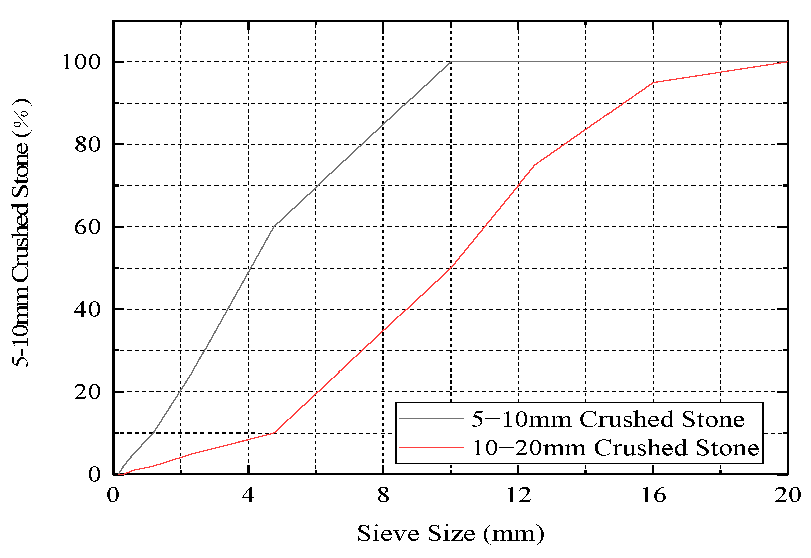
2.1.2. Coarse Aggregate
2.1.3. Fine Aggregate
2.1.4. Chemical Reagents
2.1.5. Concrete Mix Proportion
2.2. Experimental Methods
2.2.1. Experimental Equipment
- (1)
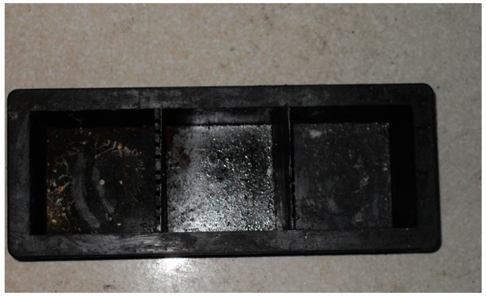
- The mold of the water group and sulfate solution is a laboratory plastic triple mold, specification 100 mm × 100 mm; after the improvement of the standard triple mold, it becomes the mold used for the electro-osmotic pulse group specimen. The middle baffle is sawed into a comb shape, the seam depth is about 90 mm, the seam width is 2~3 mm, and 9 seams are evenly sawed on each plate (Figure 1).
- (2)
- The white iron sheet, specification 100 mm × 120 mm, is mainly used for the test group to prevent cement slurry seepage during concrete molding; the perforated white iron sheet (Figure 2), 95 mm × 100 mm, is used as the electrode plate.
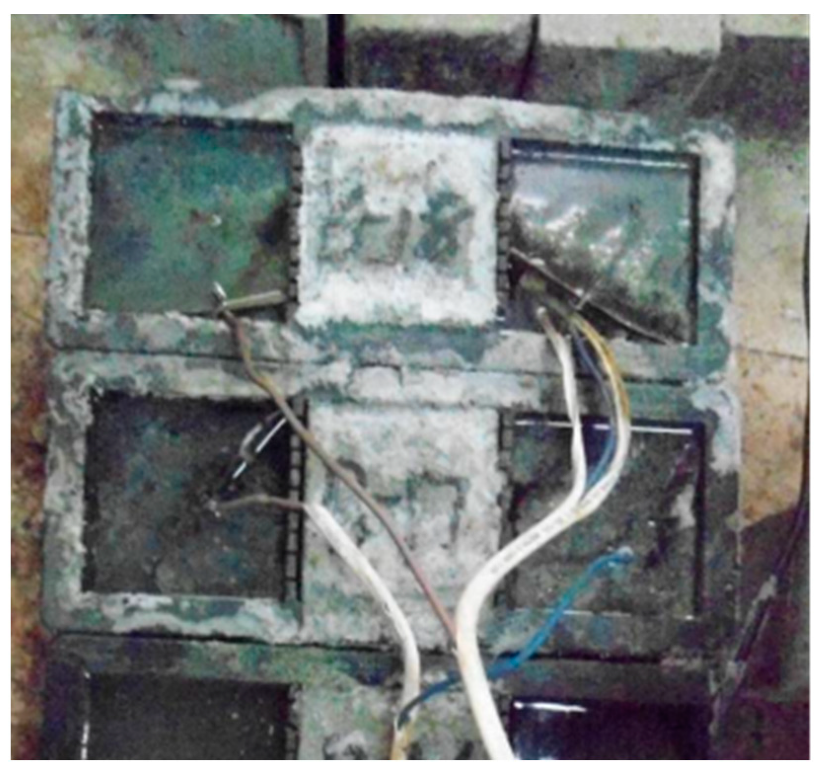
- (3)
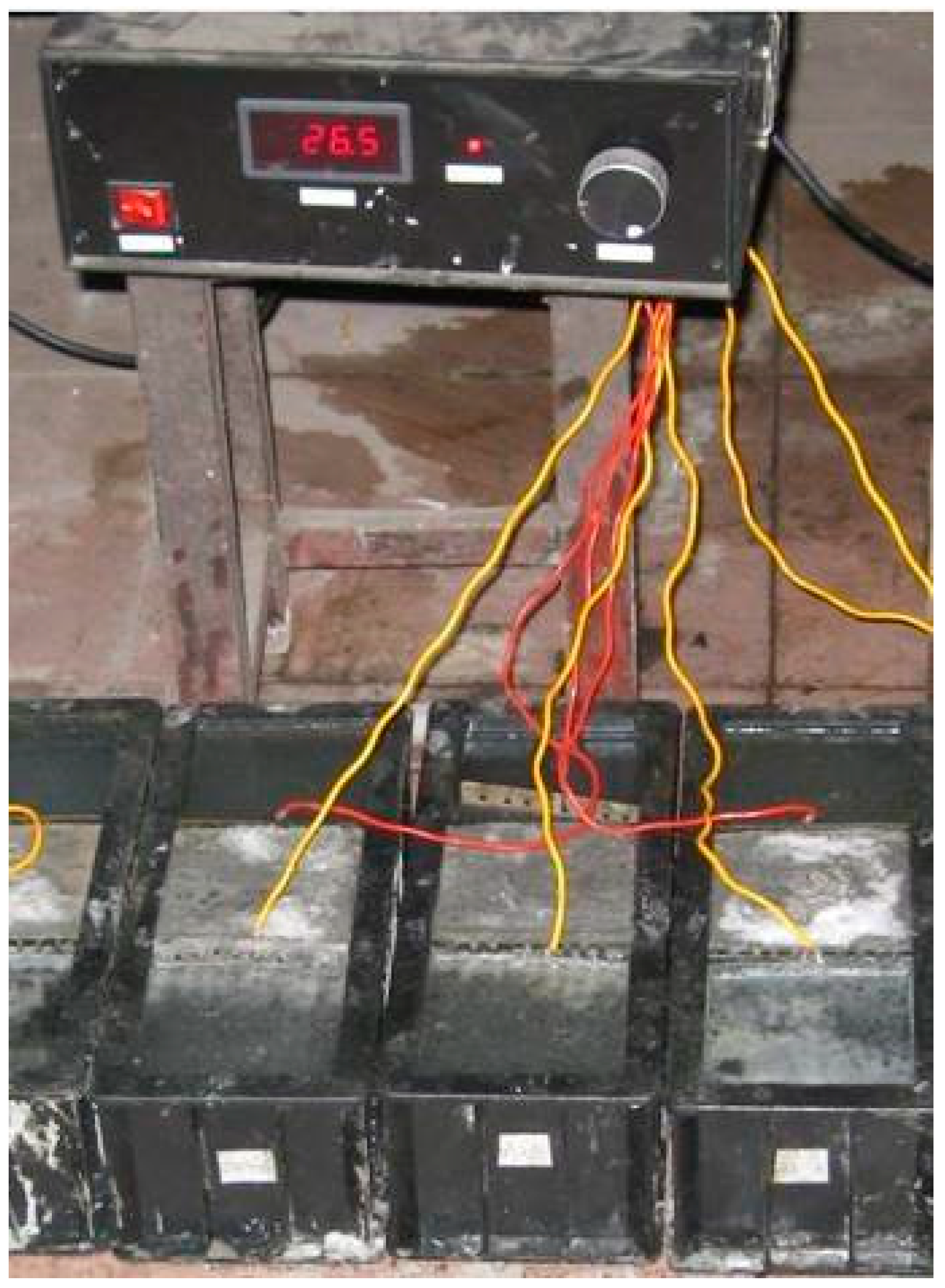
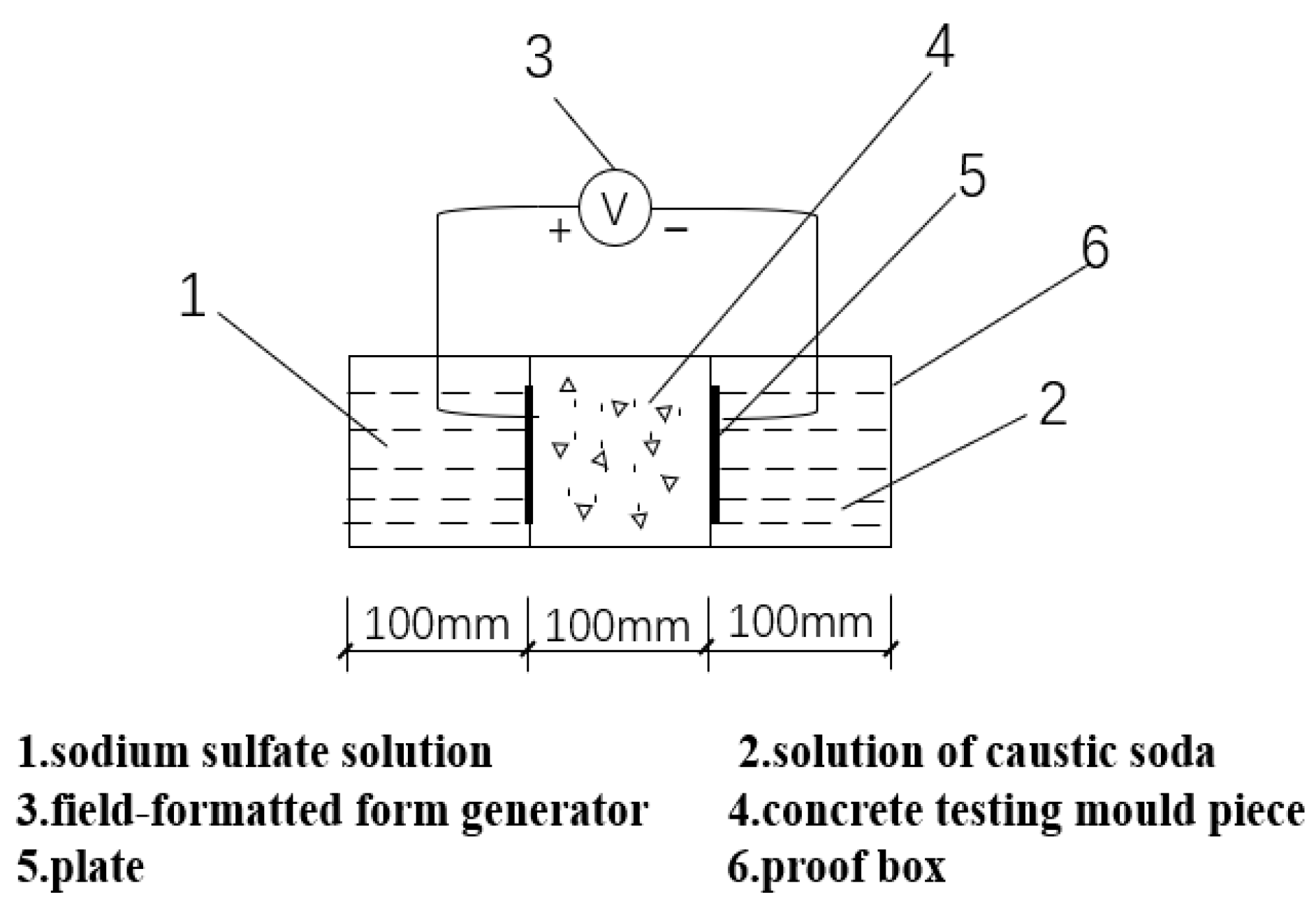
- In the mold of the electro-osmotic pulse group, only one specimen is formed in the middle, and the solution is on both sides. The electrode plate is inserted into the solution and connected to the pulse generator. Pulse electro-osmotic device (Figure 3), test group device schematic (Figure 4), pulse waveform schematic (Figure 5).
2.2.2. Experimental Procedures
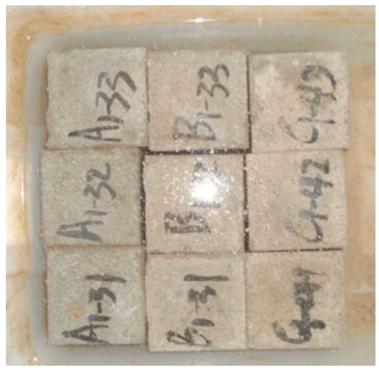
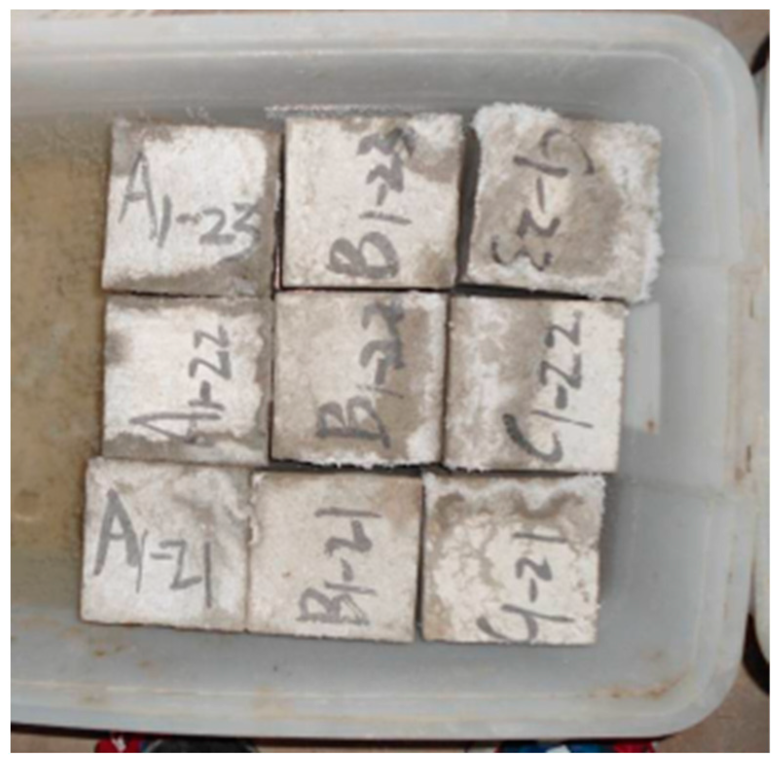
2.2.3. Specimen Molding
2.2.4. Evaluation Criteria
2.2.5. Scanning Electron Microscopy (SEM) Test
3. Results
3.1. Surface Characteristics
3.2. Mass Loss
3.3. Analysis of Experimental Results on Sulfate Attack on Concrete under Electric Field
4. Discussion
4.1. Experimental Results Analysis
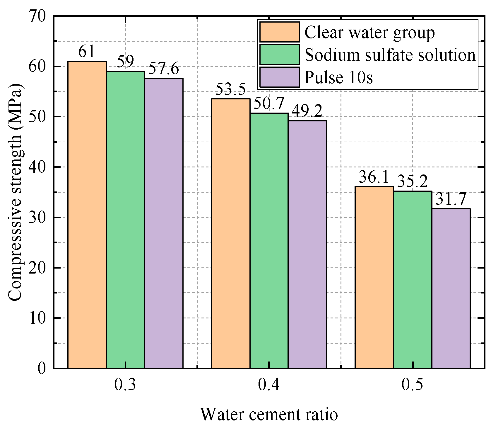
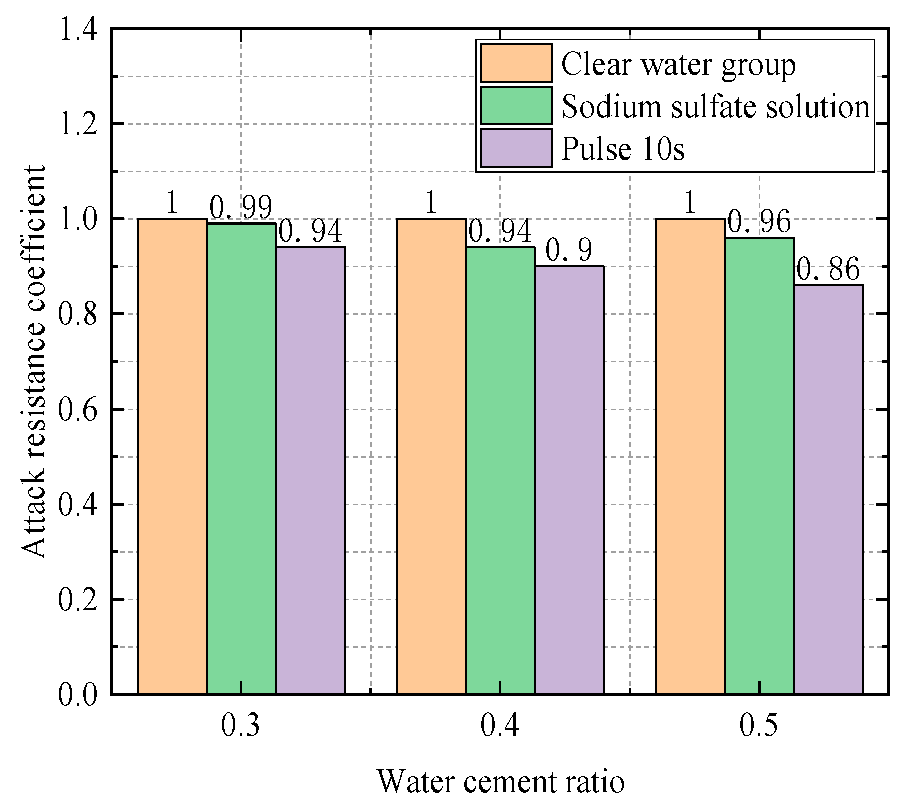
4.1.1. Influence of Water–Cement Ratio on the Experiment
- (1)
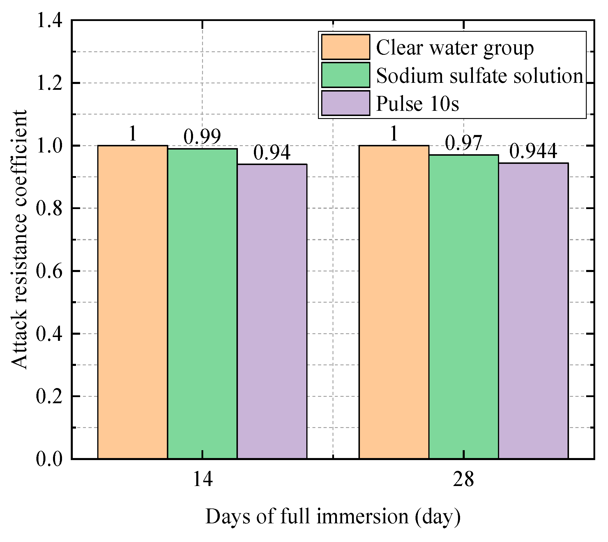
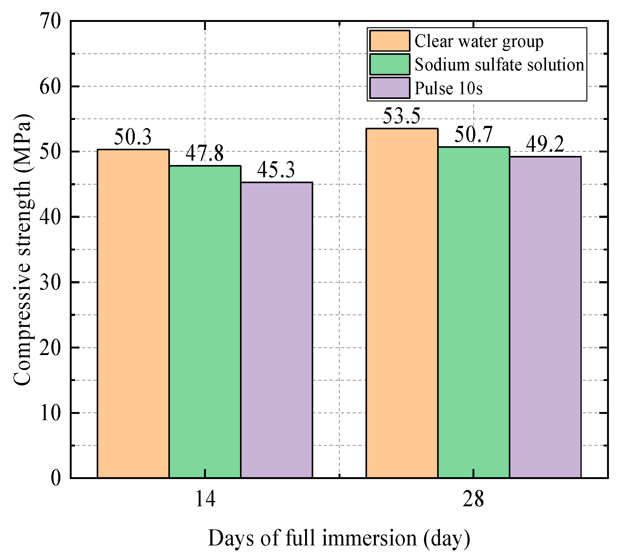
- Influence of Water–Cement Ratio at 14 Days
- (2)
- Influence of Water–Cement Ratio at 28 Days
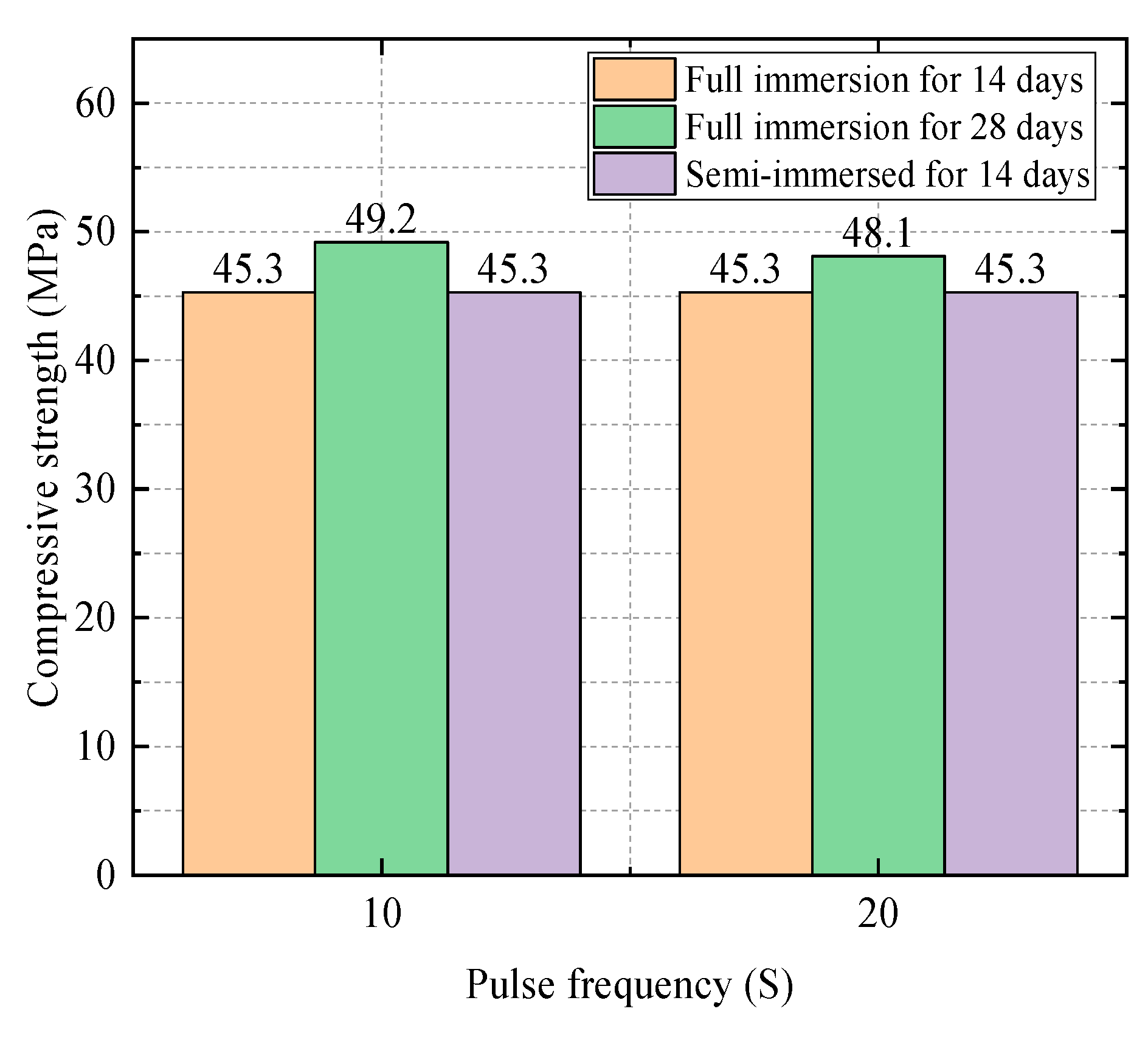
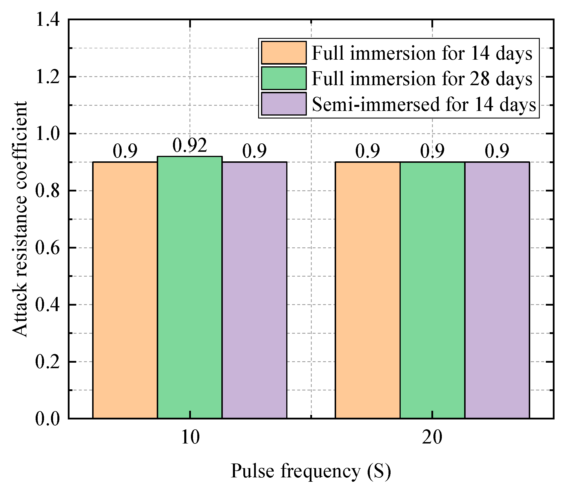
4.1.2. Impact of the Frequency of Electric Field on the Experiment
4.1.3. Impact of Age on the Experiment
- (1)
- When the water–cement ratio is 0.3:
- (2)
- When the water–cement ratio is 0.4:
- (3)
- When the water–cement ratio is 0.5:
4.1.4. Impact of Different Immersion Methods
- (1)
- When the water–cement ratio is 0.3:
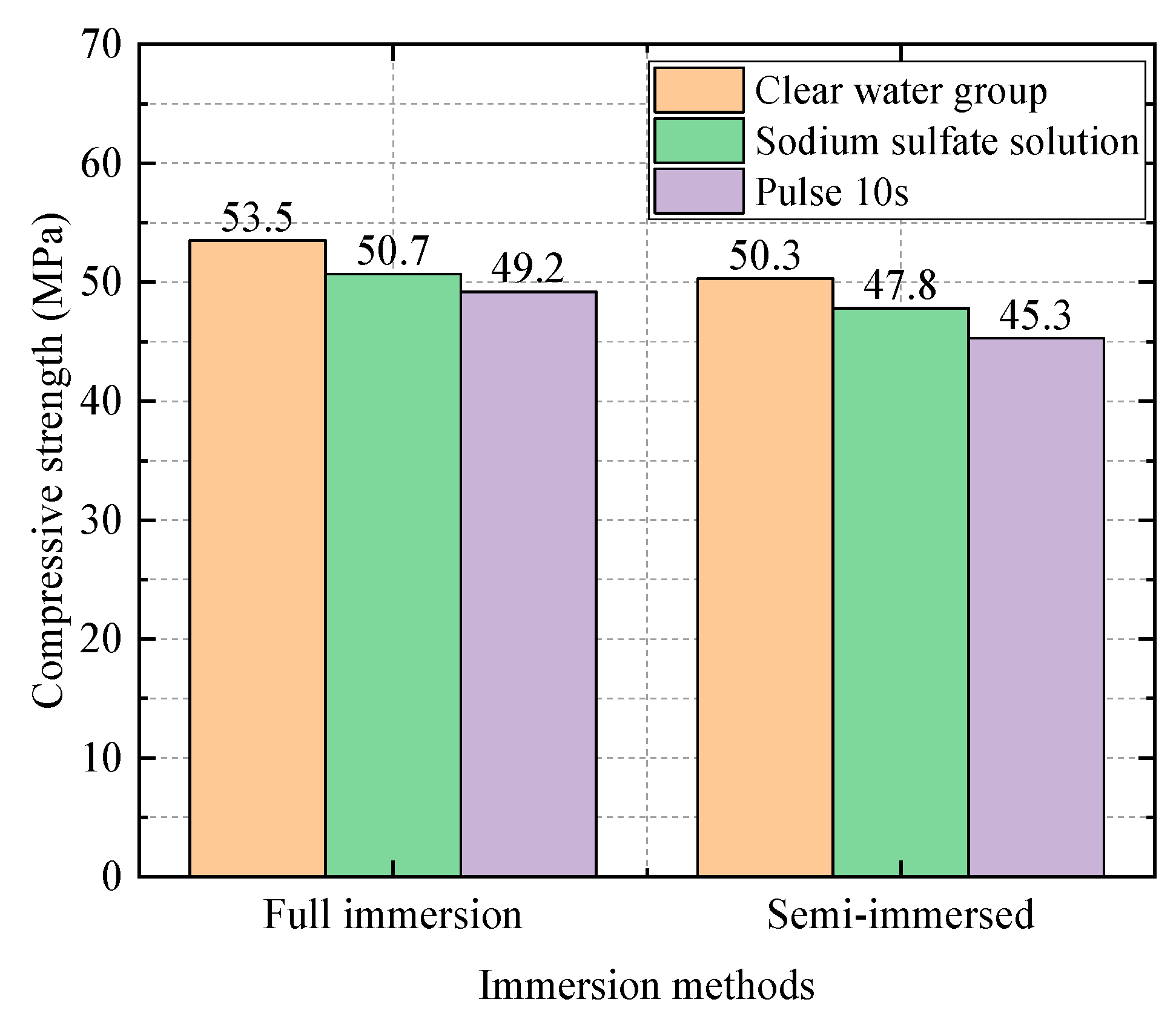
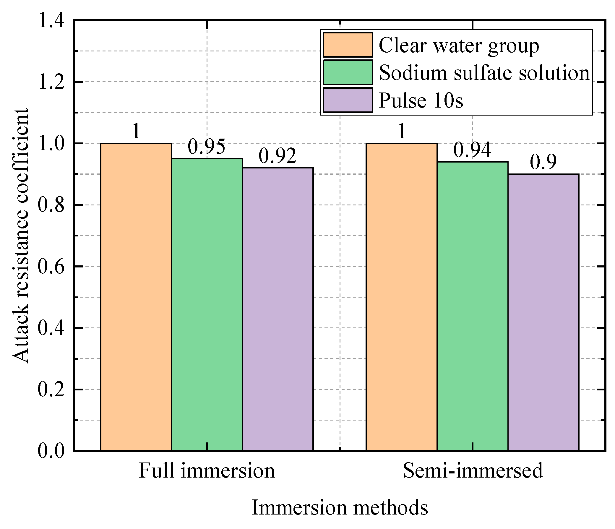
- (2)
- When the water–cement ratio is 0.4:
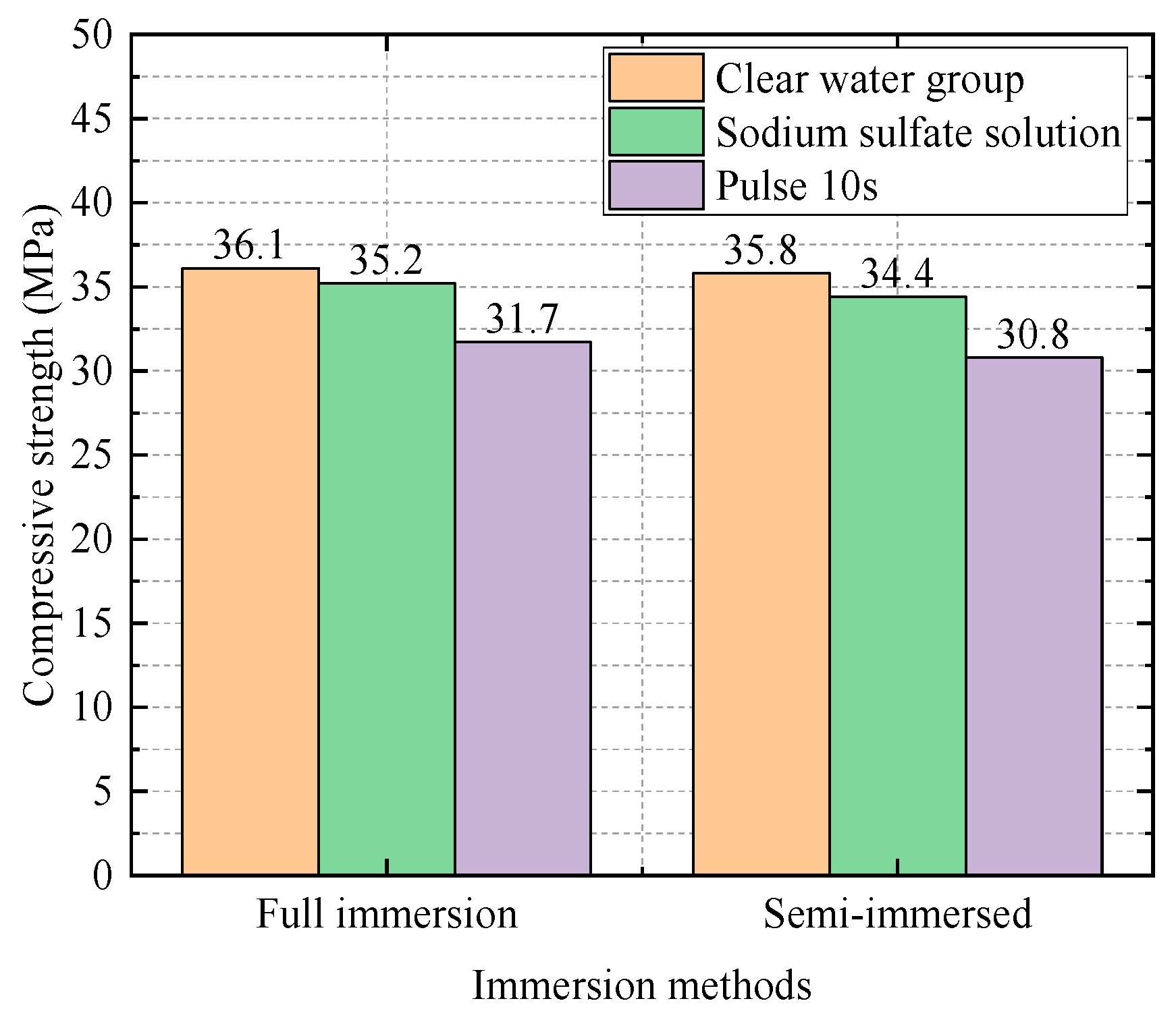
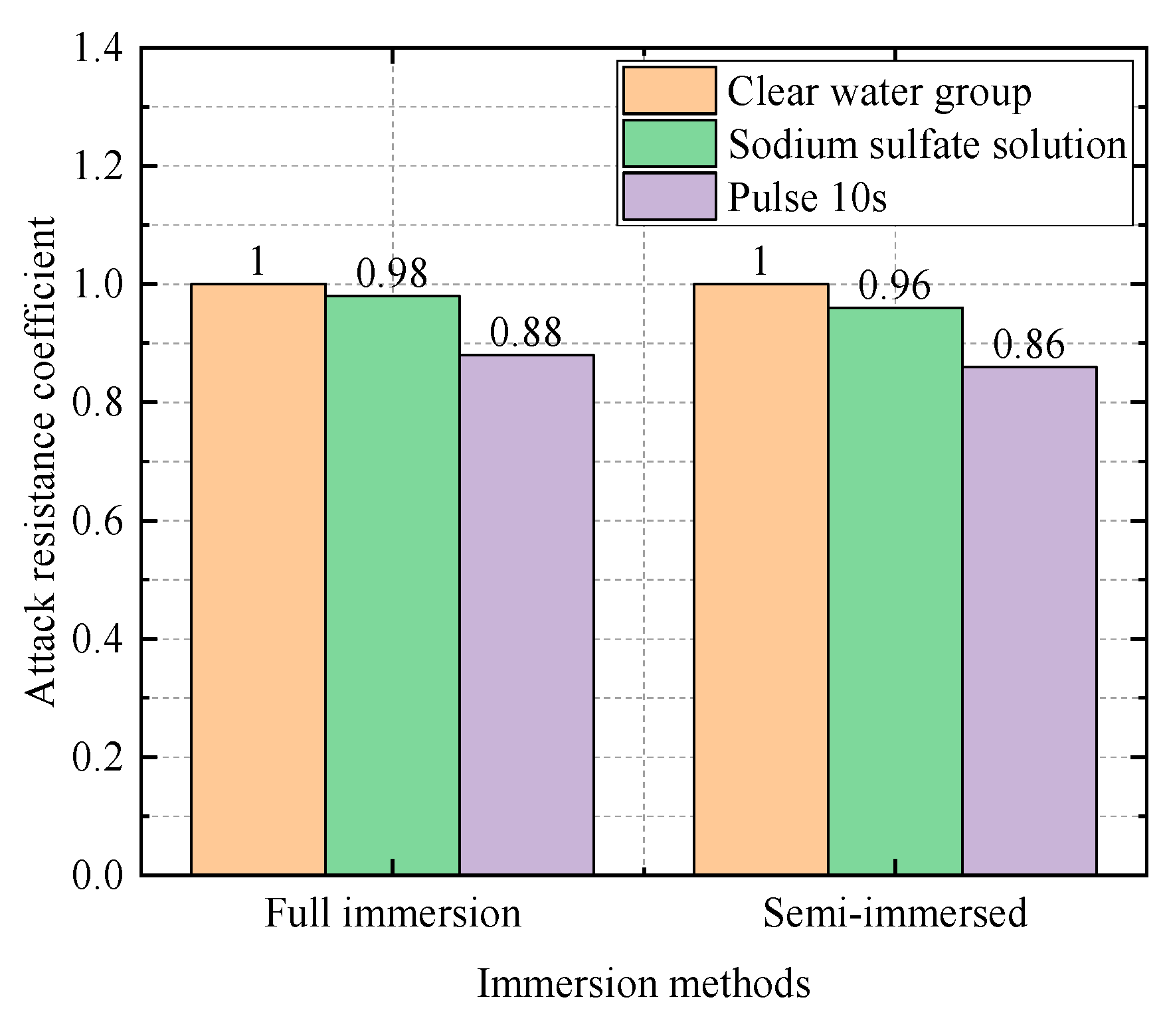
- (3)
- When the water–cement ratio is 0.5:
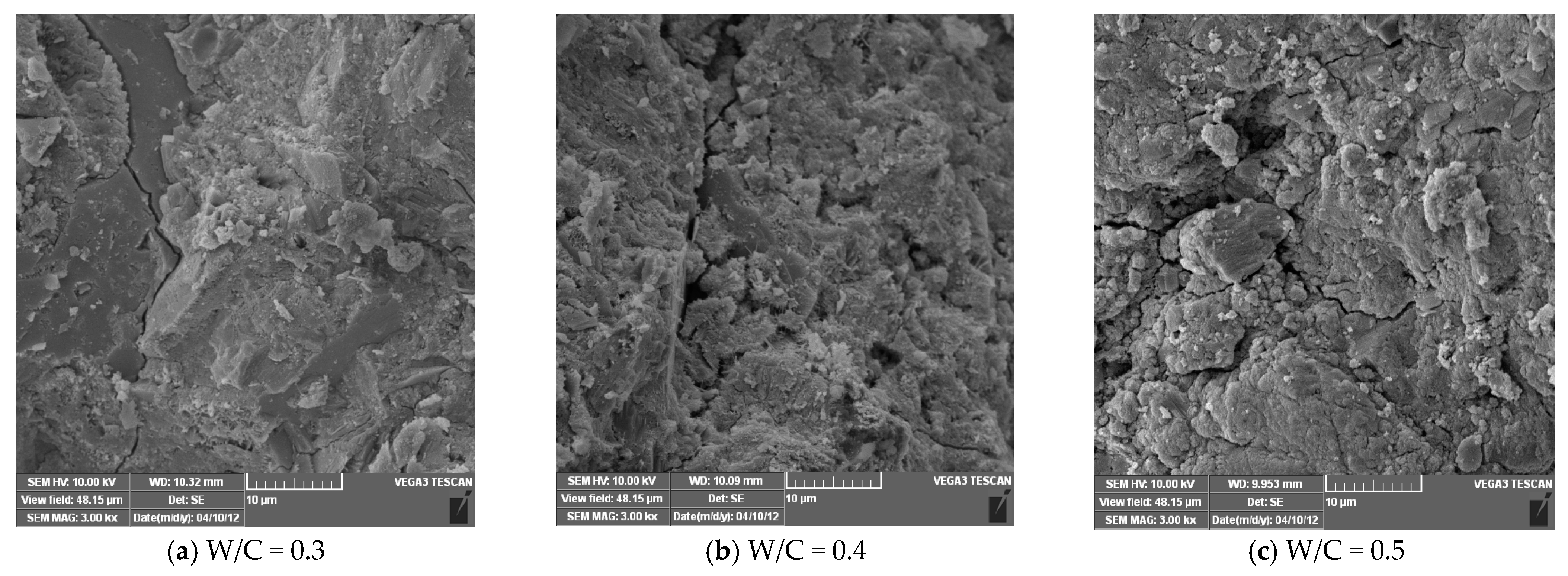
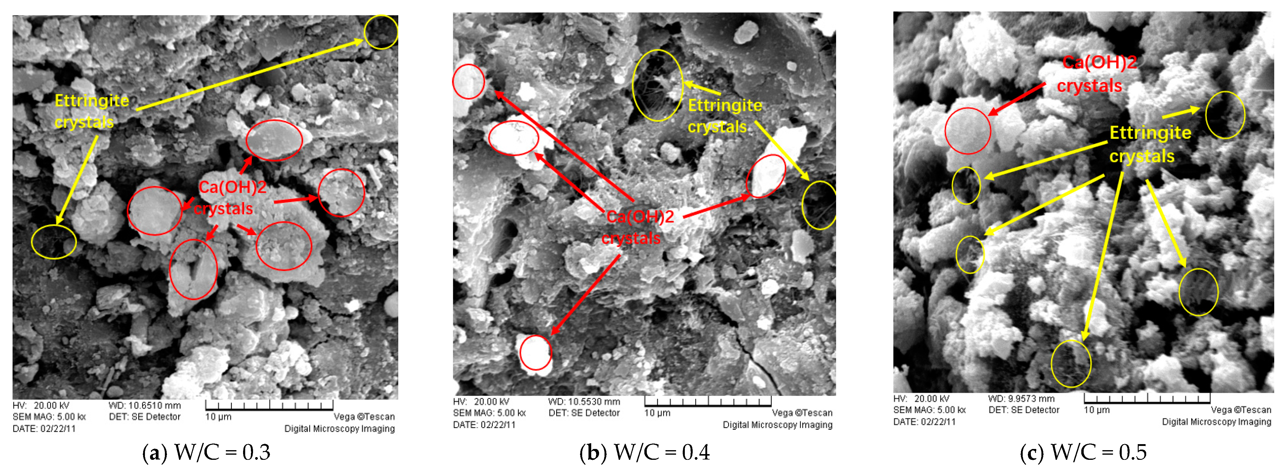
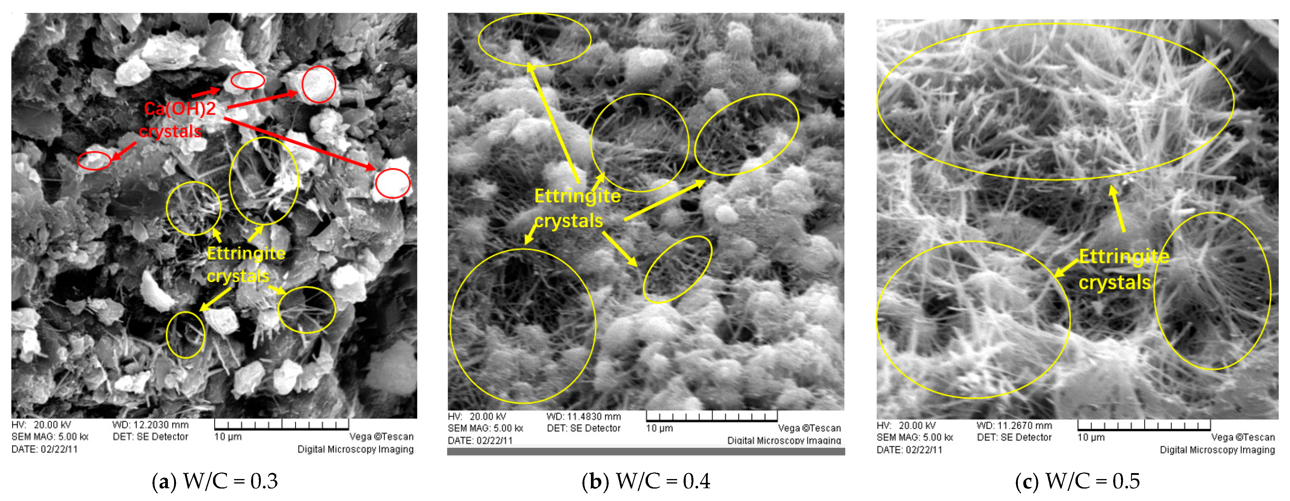
4.2. Microscopic Analysis of Ordinary Concrete Specimens
5. Conclusions
- (1)
- Electric field accelerates sulfate attack: Electric field can significantly accelerate the sulfate attack on concrete, which shows that the compressive strength of concrete in a sulfate environment is significantly reduced, especially in the case of an increasing water–cement ratio.
- (2)
- Water–cement ratio affects the rate of sulfate attack: Different water–cement ratios have a significant effect on the attack resistance of concrete. The higher the water–cement ratio, the more the porosity and connected pores in the concrete, and the faster the sulfate attack.
- (3)
- The effect of soaking time is significant: with the increase of soaking time, the mass loss and strength attenuation of concrete is significant, especially at the age of 28 days, when the attack effect of concrete under an electric field is more obvious.
- (4)
- Semi-immersed attack is more serious: In the sulfate attack environment, the compressive strength of semi-immersed concrete specimens is lower than that of fully immersed specimens, and the attack effect is more obvious.
- (5)
- Microstructure changes significantly: SEM analysis shows that under the action of the electric field, more cracks and pores are produced in the concrete, and the migration of sulfate ions is accelerated, resulting in the formation of attack products in the concrete structure.
- (6)
- To further enhance the understanding and practical application of sulfate attack resistance in concrete under electric fields, future research will focus on the impact of power plant sulfate attack on concrete and its protective measures. In particular, the potential application of fly ash in mitigating the attack effect will be emphasized. This research will help develop more durable concrete formulations, improving the long-term reliability and sustainability of infrastructure.
Author Contributions
Funding
Institutional Review Board Statement
Informed Consent Statement
Data Availability Statement
Conflicts of Interest
References
- Lawrence, D.C. Sulphate attack on concrete. Mag. Concr. Res. 2015, 42, 249–264. [Google Scholar] [CrossRef]
- Hai-Yan, Y.; Sheng-Jiao, S.; Rui, X.; Juan, Z. Study on the removal mechanism of chemically bonded chloride ions in concrete under electric field. Ferroelectrics 2019, 549, 126–136. [Google Scholar] [CrossRef]
- Xie, X.; Feng, Q.; Chen, Z.; Lu, W. Effect of the Electric Field on the Distribution Law of Chloride Ions and Microstructure in Concrete with the Addition of Mineral Admixtures. Materials 2019, 12, 1380. [Google Scholar] [CrossRef] [PubMed]
- Li, C.; Jiang, Z.; Myers, R.J.; Chen, Q.; Wu, M.; Li, J.; Monteiro, P.J. Understanding the sulfate attack of Portland cement–based materials exposed to applied electric fields: Mineralogical alteration and migration behavior of ionic species. Cem. Concr. Compos. 2020, 111, 103630. [Google Scholar] [CrossRef]
- Wang, Z.; Maekawa, K.; Gong, F. Space Averaging of Electric Field accompanying Corrosion of Reinforcement and its Verification by Pseudo-Concrete. J. Adv. Concr. Technol. 2023, 21, 25–41. [Google Scholar] [CrossRef]
- Martins, M.C.; Langaro, E.A.; Macioski, G.; Medeiros, M.H. External ammonium sulfate attack in concrete: Analysis of the current methodology. Constr. Build. Mater. 2021, 277, 122252. [Google Scholar] [CrossRef]
- Durgun, M.Y.; Sevinç, A.H. Determination of the effectiveness of various mineral additives against sodium and magnesium sulfate attack in concrete by Taguchi method. J. Build. Eng. 2022, 57, 104849. [Google Scholar] [CrossRef]
- Huang, Q.; Zhu, X.; Xiong, G.; Zhang, M.; Deng, J.; Zhao, M.; Zhao, L. Will the magnesium sulfate attack of cement mortars always be inhibited by incorporating nanosilica? Constr. Build. Mater. 2021, 305, 124695. [Google Scholar] [CrossRef]
- De Souza, D.J.; Medeiros, M.H.F.; Filho, J.H. Evaluation of external sulfate attack (Na2SO4 and MgSO4): Portland cement mortars containing fillers. Rev. IBRACON Estrut. Mater. 2020, 13, 644–655. [Google Scholar] [CrossRef]
- Yin, G.-J.; Shan, Z.-Q.; Miao, L.; Tang, Y.-J.; Zuo, X.-B.; Wen, X.-D. Finite element analysis on the diffusion-reaction-damage behavior in concrete subjected to sodium sulfate attack. Eng. Fail. Anal. 2022, 137, 106278. [Google Scholar] [CrossRef]
- Guan, B.W.; Liu, J.N.; Wu, J.W.; Chen, X.H.; Hu, Y.; Zhang, L.Q. Transport behavior of sulfate ions in concrete with attack damage. Bull. Chin. Ceram. Soc. 2020, 39, 3169–3174. [Google Scholar]
- Ran, B.; Li, K.; Fen-Chong, T.; Omikrine-Metalssi, O.; Dangla, P. Spalling rate of concretes subject to combined leaching and external sulfate attack. Cem. Concr. Res. 2022, 162, 106951. [Google Scholar] [CrossRef]
- Yin, G.-J.; Zuo, X.-B.; Sun, X.-H.; Tang, Y.-J. Macro-microscopically numerical analysis on expansion response of hardened cement paste under external sulfate attack. Constr. Build. Mater. 2019, 207, 600–615. [Google Scholar] [CrossRef]
- Cefis, N.; Comi, C. Chemo-mechanical modelling of the external sulfate attack in concrete. Cem. Concr. Res. 2017, 93, 57–70. [Google Scholar] [CrossRef]
- Yi, C.F.; Zheng, C.; Vivek, B. A non-homogeneous model to predict the service life of concrete subjected to external sulfate attack. Constr. Build. Mater. 2019, 212, 254–265. [Google Scholar] [CrossRef]
- Yin, G.-J.; Zuo, X.-B.; Li, X.-N.; Zou, Y.-X. An integrated macro-microscopic model for concrete deterioration under external sulfate attack. Eng. Fract. Mech. 2020, 240, 107345. [Google Scholar] [CrossRef]
- Li, J.; Xie, F.; Zhao, G.; Li, L. Experimental and numerical investigation of cast-in-situ concrete under external sulfate attack and drying-wetting cycles. Constr. Build. Mater. 2020, 249, 118789. [Google Scholar] [CrossRef]
- Zhang, C.-L.; Chen, W.-K.; Mu, S.; Šavija, B.; Liu, Q.-F. Numerical investigation of external sulfate attack and its effect on chloride binding and diffusion in concrete. Constr. Build. Mater. 2021, 285, 122806. [Google Scholar] [CrossRef]
- Wang, H.; Chen, Z.; Li, H.; Sun, X. Numerical simulation of external sulphate attack in concrete considering coupled chemo-diffusion-mechanical effect. Constr. Build. Mater. 2021, 292, 123325. [Google Scholar] [CrossRef]
- Silva, D.; Fajardo-San-Miguel, G.; Escadeillas, G.; Cruz-Moreno, D. Surface treatment with silicon-based nanoparticles in Portland cement specimens subjected to physical sulfate attack. Case Stud. Constr. Mater. 2023, 18, e01795. [Google Scholar] [CrossRef]
- Esselami, R.; Wilson, W.; Tagnit-Hamou, A. An accelerated physical sulfate attack test using an induction period and heat drying: First applications to concrete with different binders including ground glass pozzolan and limestone filler. Constr. Build. Mater. 2022, 345, 128046. [Google Scholar] [CrossRef]
- Yu, X.; Li, S.; Zheng, J.; Chang, X.; Liao, Y.; Chen, D. Degradation process of reinforced concrete under chloride and sulfate attack with and without electric field. J. Build. Eng. 2023, 78, 107588. [Google Scholar] [CrossRef]
- Jiang, L.; Niu, D.T.; Sun, Y.Z.; Fei, Q.N. Ultrasonic testing and microscopic analysis on concrete under sulfate attack and cyclic environment. J. Cent. South Univ. 2013, 21, 4723–4731. [Google Scholar] [CrossRef]
- Jiang, L.; Niu, D.; Yuan, L. Microstructure Analyses of Concrete Attacked by Wet-Dry Cycling and Sulfate Solution. In Proceedings of the Seventh International Conference on Concrete under Severe Conditions—Environment and Loading, Nanjing, China, 23–25 September 2013. [Google Scholar]
- Müllauer, W.; Beddoe, R.E.; Heinz, D. Sulfate attack expansion mechanisms. Cem. Concr. Res. 2013, 52, 208–215. [Google Scholar] [CrossRef]
- Cefis, N.; Comi, C. Degradation of Concrete Structures due to External Sulfate Attack. Key Eng. Mater. 2016, 711, 310–318. [Google Scholar] [CrossRef]
- Yang, Y.; Zhang, Y.; She, W.; Wu, Z.; Liu, Z.; Ding, Y. Nondestructive monitoring the deterioration process of cement paste exposed to sodium sulfate solution by X-ray computed tomography. Constr. Build. Mater. 2018, 186, 182–190. [Google Scholar] [CrossRef]
- Zhang, S.; Wang, Y.; Guo, B.; Lu, Y.; Niu, D. Characteristic fractal evolution of concrete hole structure under the coupling of temperature field and sulfate erosion. J. Silic. 2024, 52, 474–484. [Google Scholar]
- Carrión, A.; Genovés, V.; Gosálbez, J.; Miralles, R.; Payá, J. Ultrasonic signal modality: A novel approach for concrete damage evaluation. Cem. Concr. Res. 2017, 101, 25–32. [Google Scholar] [CrossRef]
- Zhao, Y.; Ren, S.; Wang, L.; Zhang, P.; Liu, R.; Chen, F.; Jiang, X. Acoustic Emission and Physicomechanical Properties of Concrete under Sulfate Attack. J. Mater. Civ. Eng. 2021, 33, 04021016. [Google Scholar] [CrossRef]
- Zhang, M.; Yang, L.-M.; Guo, J.-J.; Liu, W.-L.; Chen, H.-L. Mechanical Properties and Service Life Prediction of Modified Concrete Attacked by Sulfate Corrosion. Adv. Civ. Eng. 2018, 2018, 8907363. [Google Scholar] [CrossRef]
- Zhu, F.; Qiao, H.; Li, J. Sulfate attack resistance and reliability analysis of fibre-reinforced concrete materials. Emerg. Mater. Res. 2020, 9, 1121–1130. [Google Scholar] [CrossRef]
- Zhang, Z.; Jin, X.; Luo, W. Long-term behaviors of concrete under low-concentration sulfate attack subjected to natural variation of environmental climate conditions. Cem. Concr. Res. 2019, 116, 217–230. [Google Scholar] [CrossRef]
- GB/T 50081-2019; Standard for Test Methods of Concrete Physical and Mechanical Properties. National Standards of the People’s Republic of China: Beijing, China, 2019.
- GB/T 50082-2009; Standard Test Methods for Long-Term Performance and Durability of Ordinary Concrete. National Standards of the People’s Republic of China: Beijing, China, 2009.


| Materials | SiO2 (%) | Fe2O3 (%) | Al2O3 (%) | CaO (%) | MgO (%) | SO3 (%) | Total Alkali Content (%) | Ignition Loss |
|---|---|---|---|---|---|---|---|---|
| Ordinary 42.5R | 21.3 | 2.53 | 5.79 | 60.15 | 2.35 | 2.54 | 0.72 | 3.66 |
| Standard Consistency (%) | Initial Setting Time (min) | Final Setting Time (min) | Stability (Slump Test) | Compressive Strength (MPa) | Flexural Strength (MPa) | ||
|---|---|---|---|---|---|---|---|
| 3 d | 28 d | 3 d | 28 d | ||||
| 28.4 | 179 | 239 | No cracks observed No warping observed | 5.5 | 27.6 | 8.8 | 53.0 |
| Particle Size (mm) | Bulk Density (g/cm3) | Particle Density (g/cm3) | Porosity (%) | ||
|---|---|---|---|---|---|
| Loose | Dense | Loose | Dense | ||
| 5~10 | 2670 | 1380 | 1470 | 48.3 | 44.9 |
| 10~20 | 2670 | 1400 | 1520 | 47.6 | 43.1 |
| Water–Cement Ratio | Water/kg·m−3 | Cement/kg·m−3 | Sand/kg·m−3 | Crushed Stone/kg·m−3 |
|---|---|---|---|---|
| 0.3 | 190 | 633 | 602 | 1025 |
| 0.4 | 190 | 475 | 660 | 1125 |
| 0.5 | 190 | 380 | 696 | 1184 |
| Group | Water Group | Sodium Sulfate Solution Group | Electric Field Group (10 s) | Electric Field Group (20 s) | |||||
|---|---|---|---|---|---|---|---|---|---|
| Immersion Method | Full Immersion | Partial Immersion | Full Immersion | Partial Immersion | Full Immersion | Partial Immersion | Full Immersion | Partial Immersion | |
| Water–Cement Ratio | 0.3 | 6 | 3 | 6 | 3 | 6 | 3 | 0 | 0 |
| 0.4 | 6 | 3 | 6 | 3 | 6 | 3 | 6 | 3 | |
| 0.5 | 6 | 3 | 6 | 3 | 6 | 3 | 0 | 0 | |
| Water–Cement Ratio | Average Mass of Specimens (kg) | Average Mass of Specimens (kg) | Mass Loss Rate k (%) | |
|---|---|---|---|---|
| 0.3 | Water Group | 2.50 | 2.51 | 0.53 |
| Sodium Sulfate Solution Group | 2.53 | 2.55 | 1.06 | |
| Electric field group (10 s) | 2.43 | 2.45 | 0.55 | |
| 0.4 | Water Group | 2.44 | 2.46 | 0.82 |
| Sodium Sulfate Solution Group | 2.45 | 2.46 | 0.54 | |
| Electric field group (10 s) | 2.42 | 2.44 | 0.83 | |
| Electric field group (20 s) | 2.47 | 2.49 | 0.81 | |
| 0.5 | Water Group | 2.53 | 2.55 | 0.79 |
| Sodium Sulfate Solution Group | 2.55 | 2.56 | 0.52 | |
| Electric field group (10 s) | 2.47 | 2.50 | 1.35 |
| Water–Cement Ratio | Average Mass of Specimens (kg) | Average Mass of Specimens (kg) | Mass Loss Rate k (%) | |
|---|---|---|---|---|
| 0.3 | Water Group | 2.46 | 2.45 | −0.41 |
| Sodium Sulfate Solution Group | 2.45 | 2.45 | 0 | |
| Electric field group (10 s) | 3.57 | 3.52 | −1.40 | |
| 0.4 | Water Group | 2.48 | 2.46 | −0.81 |
| Sodium Sulfate Solution Group | 2.47 | 2.48 | 0.41 | |
| Electric field group (10 s) | 3.45 | 3.42 | −0.87 | |
| Electric field group (20 s) | 3.43 | 3.40 | −0.87 | |
| 0.5 | Water Group | 2.41 | 2.39 | −0.83 |
| Sodium Sulfate Solution Group | 2.42 | 2.42 | 0 | |
| Electric field group (10 s) | 3.35 | 3.4 | −1.65 |
| Water–Cement Ratio | Average Mass of Specimens (kg) | Average Mass of Specimens (kg) | Mass Loss Rate k (%) | |
|---|---|---|---|---|
| 0.3 | Water Group | 2.45 | 2.44 | −0.41 |
| Sodium Sulfate Solution Group | 2.43 | 2.43 | 0 | |
| Electric field group (10 s) | 3.42 | 3.41 | −0.30 | |
| 0.4 | Water Group | 2.46 | 2.46 | 0 |
| Sodium Sulfate Solution Group | 2.46 | 2.44 | −0.81 | |
| Electric field group (10 s) | 3.45 | 3.42 | −0.87 | |
| Electric field Group (20 s) | 3.39 | 3.39 | 0 | |
| 0.5 | Water Group | 2.41 | 2.39 | −0.83 |
| Sodium Sulfate Solution Group | 2.42 | 2.38 | −1.65 | |
| Electric field group (10 s) | 3.35 | 3.35 | 0 |
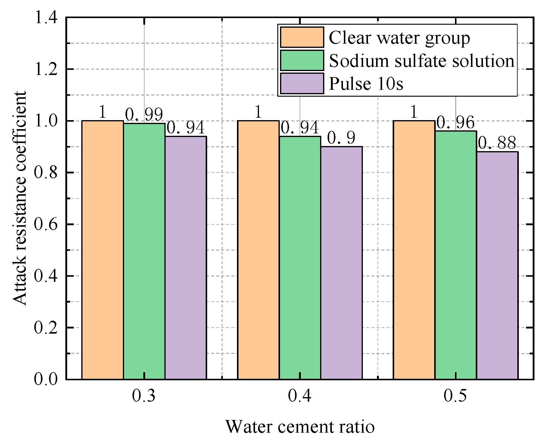
| Water–Cement Ratio | Group | Compressive Strength (Mpa) | Relative Attack Resistance Coefficient K |
|---|---|---|---|
| 0.3 | Water Group | 60.7 | 1 |
| Sodium Sulfate Solution Group | 60.6 | 0.99 | |
| Electric field group (10 s) | 56.5 | 0.94 | |
| 0.4 | Water Group | 50.3 | 1 |
| Sodium Sulfate Solution Group | 47.8 | 0.94 | |
| Electric field group (10 s) | 45.3 | 0.90 | |
| Electric field group (20 s) | 45.3 | 0.90 | |
| 0.5 | Water Group | 35.8 | 1 |
| Sodium Sulfate Solution Group | 34.4 | 0.96 | |
| Electric field group (10 s) | 30.8 | 0.88 |
| Water–Cement Ratio | Group | Compressive Strength (Mpa) | Relative Attack Resistance Coefficient K |
|---|---|---|---|
| 0.3 | Water Group | 61 | 1 |
| Sodium Sulfate Solution Group | 59 | 0.97 | |
| Electric field group (10 s) | 57.6 | 0.944 | |
| 0.4 | Water Group | 53.5 | 1 |
| Sodium Sulfate Solution Group | 50.7 | 0.95 | |
| Electric field group (10 s) | 49.2 | 0.92 | |
| Electric field group (20 s) | 48.1 | 0.90 | |
| 0.5 | Water Group | 36.1 | 1 |
| Sodium Sulfate Solution Group | 35.2 | 0.98 | |
| Electric field group (10 s) | 31.7 | 0.88 |
| Water–Cement Ratio | Group | Compressive Strength (Mpa) | Relative Attack Resistance Coefficient K |
|---|---|---|---|
| 0.3 | Water Group | 60.7 | 1 |
| Sodium Sulfate Solution Group | 60.6 | 0.99 | |
| Electric field group (10 s) | 56.5 | 0.94 | |
| 0.4 | Water Group | 50.3 | 1 |
| Sodium Sulfate Solution Group | 47.8 | 0.94 | |
| Electric field group (10 s) | 45.3 | 0.90 | |
| Electric field group (20 s) | 45.3 | 0.90 | |
| 0.5 | Water Group | 35.8 | 1 |
| Sodium Sulfate Solution Group | 34.4 | 0.96 | |
| Electric field group (10 s) | 30.8 | 0.86 |
Disclaimer/Publisher’s Note: The statements, opinions and data contained in all publications are solely those of the individual author(s) and contributor(s) and not of MDPI and/or the editor(s). MDPI and/or the editor(s) disclaim responsibility for any injury to people or property resulting from any ideas, methods, instructions or products referred to in the content. |
© 2024 by the authors. Licensee MDPI, Basel, Switzerland. This article is an open access article distributed under the terms and conditions of the Creative Commons Attribution (CC BY) license (https://creativecommons.org/licenses/by/4.0/).
Share and Cite
Liu, H.; Shi, N.; Han, K.; Fu, X.; Fang, Y. Study on the Attack of Concrete by External Sulfate under Electric Fields. Coatings 2024, 14, 1008. https://doi.org/10.3390/coatings14081008
Liu H, Shi N, Han K, Fu X, Fang Y. Study on the Attack of Concrete by External Sulfate under Electric Fields. Coatings. 2024; 14(8):1008. https://doi.org/10.3390/coatings14081008
Chicago/Turabian StyleLiu, Huanqin, Nuoqi Shi, Kaizhao Han, Xu Fu, and Yuexin Fang. 2024. "Study on the Attack of Concrete by External Sulfate under Electric Fields" Coatings 14, no. 8: 1008. https://doi.org/10.3390/coatings14081008
APA StyleLiu, H., Shi, N., Han, K., Fu, X., & Fang, Y. (2024). Study on the Attack of Concrete by External Sulfate under Electric Fields. Coatings, 14(8), 1008. https://doi.org/10.3390/coatings14081008