Article

Endurance to Multiple Factors of Water-Based Electrically Conductive Paints with Metallic Microparticles

by
Alina Ruxandra Caramitu
1,
Romeo Cristian Ciobanu
2,*,
Mihaela Aradoaei
2,
Magdalena Valentina Lungu
1,
Nicoleta Oana Nicula
1 and
Eduard Marius Lungulescu
1
1
National Institute for Research and Development in Electrical Engineering ICPE-CA Bucharest, 030138 Bucharest, Romania
2
Department of Electrical Measurements and Materials, Gheorghe Asachi Technical University, 700050 Iasi, Romania
*
Author to whom correspondence should be addressed.
Coatings 2024, 14(8), 1016; https://doi.org/10.3390/coatings14081016 (registering DOI)
Submission received: 27 June 2024 / Revised: 30 July 2024 / Accepted: 8 August 2024 / Published: 10 August 2024

Abstract

:
The paper describes the innovative adaptation of some specific environmental tests from general organic coatings towards newly developed water-based composite paints with metallic particles (Al and Fe), with a high content of metal (10% and respectively 20%) for electromagnetic shielding applications. Electrical conductivity is the most affected dielectric parameter under both by UV radiation and thermal exposure. The paints with 20% metallic powder are more sensitive to environmental factors, and the influence of metal type could also be emphasized in relation to the dielectric feature evolution vs. exposure time. The action of mold significantly decreases the dielectric features of paints, but the weathering aging effect is much more enhanced if the samples are cumulatively submitted to thermal aging and respectively UV exposure, along with the action of mold. The potential application of the study is related mainly to the development of new autonomous electric cars, which need special conditions of electromagnetic shielding, under the circumstances that the conductive paint layers are normally very sensitive to environmental factors, affecting the equipment performance and security.

1. Introduction

Electrically conductive paint is commonly created by blending an electrically conductive pigment with a non-conductive resin binder. Potential uses for these paints include electromagnetic shielding, circuit prototyping, repairing, guarding against electrostatic discharge, and preventing galvanic corrosion. The binder preserves the paint’s quality and helps it stick to surfaces, while the conductive pigment enables electrical current to flow through. Metallic particles like copper, silver, and other soft malleable metals are very conductive and enable the current to transmit efficiently in liquid media with solvents. These particles are extremely fine to maintain the wetting and adhesion qualities that regular paints are known for. Electric charges flow through the conductive fillers by making brief jumps between particles in the matrix. This process works best with densely packed fillers in the form of flakes or tubes. Spherical particles may not be the best for achieving maximum conductivity, but when paired with flakes, they can offer a better finish and enhanced conductivity. Besides shape, fillers also vary significantly in electrical conductivity, corrosion resistance, and cost. Actual technologies and related conductive paint products on the market use a limited number and low content of pigments, including branched carbon powder, nickel flakes, silver coated copper flakes, and/or silver flakes, e.g., [1,2,3,4,5,6,7,8], and most of them are based on non-conductive resin binder and organic solvents, which are not environmentally friendly. Water-based electrically conductive paints are specialized coatings that use water as the primary solvent. They are designed to provide electrical conductivity and to be environmentally friendly, representing a versatile solution for situations where traditional solvent-based conductive paints are impractical or environmentally harmful. Water-based conductive paints are used in a variety of industries, including electronics, automotive, and energy, being applied to surfaces for electromagnetic interference (EMI) shielding, antistatic coatings, or other uses that require electrical conductivity on non-metallic substrates. Although they have considerable potential for use, almost no research has examined the reliability of paint films on plastic substrates, although such evaluations would be essential, especially for automotive equipment operating in diverse environments and even in severe conditions.
In current practice for aerospace or construction applications, specific tests have been described to evaluate, for example, the effect of solar absorption, in order to develop infrared-reflective paints [9,10,11] or solar-absorbing paints on metal support [12,13]. However, there are no similar tests defined for conductive paints. On the other hand, some researchers have examined the antifouling properties of electrodes printed with conductive paints [14], but these studies have only focused on improving the printing technology, not evaluating the reliability of the paints. The methodology for testing for endurance of multilayer water-based electrically conductive paints to multiple factors may be based on related research on environmental effects upon composite organic coatings, e.g., in [15,16,17].
The novelty of the presented research consists in the adaptation of some specific environmental tests from general organic coatings towards newly developed water-based composite paints with metallic particles (Al and Fe). The originality of the presented recipes lies in the fact that they include a high content of metal (10% or 20%) and special additives to allow them to offer high electromagnetic shielding features and high reliability on different plastic substrates. All ingredients used in paint formulation respects the European Union regulatory framework related to REACH (Registration, Evaluation, Authorization and Restriction of Chemical Substances) in terms that no “Substances of Very High Concern” (SVHCs) were used. The potential application is related mainly in the development of new autonomous electric cars, which need special conditions of electromagnetic shielding to avoid interference and protect the large quantity of sensors and IoT-related devices, but the electromagnetic shielding efficiency is normally very sensitive to environmental factors, which can deteriorate the conductive paint layers and so affect the equipment performance and security.

2. Preparation of Paints with Large Quantities of Metallic Microparticles

2.1. Materials and Methods

The research was oriented towards water-based acrylic paints, which are versatile in applications, offering good water resistance; a wide range of color shades—if necessary to embed; resistance to algae and mold growth; good vapor permeability; resistance to environmental phenomena; high elasticity of the film; high coverage; and easy application (allowing mechanical application by spraying—ideal for the electronic or automotive industry). The basic formula of the water-based acrylic paint is pigment—here also metallic powder, binder (resin), solvent—water, and additives.

2.1.1. Raw Materials

The raw materials for obtaining the paints that are the subject of this work were:
o
Polyoxyethylene (25) octyl phenyl ether, butyl acrylate, vinyl acetate, dibutyl phthalate, sodium dodecyl sulfate. All these substances are procured from authorized distributors;
o
Microparticles powders (source: Laiwu Powder Material Co. Ltd., Shanghai, China).

2.1.2. Testing Equipment and Methods

Two types of paints were obtained, coded as V1 and V2, with the following composition: V1—Solvent—water 42%; Polyoxyethylene (25) octyl phenyl ether—surfactant and buffer 2%; butyl acrylate and vinyl acetate—binder 43%; Dibutylphthalate—plasticizer 1%; sodium dodecyl sulfate—antiagglomerant and compatibilizer 1%; initiator, reducing agent, defoamer, preservative and crosslinking polymer—all 1%, metallic powder 10% (two variants, with Al and respectively Fe powder); and V2—Solvent—water 37%; Polyoxyethylene (25) octyl phenyl ether—surfactant and buffer 2%; butyl acrylate and vinyl acetate—binder 38%; Dibutylphthalate—plasticizer 1%; sodium dodecyl sulfate—antiagglomerant and compatibilizer 1%; initiator, reducing agent, defoamer, preservative and crosslinking polymer—all 1%, metallic powder 20% (two variants, with Al and Fe powder), as described in [18].
To homogenize the paints and avoid the agglomeration of the Al and Fe powders, an ultrasonication was applied for 30 min when mixing the metallic powders with the solvent, another 15 min when adding the binder and additives, and finally for 5 min before applying the paints upon support. The ultrasonication of paint mixtures was made in the USC-T type VWR ultrasonic bath: capacity 2.8 L; frequency 45k Hz; size of the tub: 237 × 134 × 100 mm (VWR International—Avantor Inc., Radnor, PA, USA). The paints were deposited on polycarbonate support, which was preliminarily sandblasted. The sandblasting process was performed with an Eco Pressure 80–140 P Sandblasting Booth (Sablast Techn., Targu Mures, Romania), maximum pressure: 10 bar, loading capacity: 350 Kg, abrasive grit: max. 1.5 mm; degree of sandblasting: SA-3 [18].
The composite samples obtained were coded as M1 for V1 + Al, M2 for V2 + Al, M3 for V1 + Fe, and M4 for V2 + Fe.
For the powders used, SEM structural analyses were initially carried out to verify the morphology and particle sizes. The equipment with which the SEM structural analyses were carried out was a scanning electron microscope with field emission source and focused ion beam from ZEISS. This equipment is dedicated to the study of microscopic structures and inorganic and organic surfaces. The images were taken at an acceleration voltage of 5 kV with a working distance of 4.3–4.5 mm. The detector used was the secondary electron detector of the Everhart Thornley type with the Faraday cup in the sample chamber, resulting in micrographs that highlight the morphology and topography of the analyzed surfaces. Also, we employed an active load compensation system (local) with N2 gas was used on the surface of the analyzed sample (CC—charge compensation).
The FTIR spectra of the paint samples were recorded with a Jasco 4200 spectrometer (Jasco International Co., Ltd., Tokyo, Japan) coupled with the accessory ATR (Attenuated Total Reflectance) Jasco Pro 470-H. The samples were measured directly by placing them on the crystal of the ATR device and by pressing with a controlled force, and the spectra recording conditions were as follows: spectral range: 4000–500 cm−1; resolution: 4 cm−1; number of scans/spectrum: 50.
The determination of the thickness of the paint layers (average of 3 measurements) was made with the PosiTector® 200 tester (DeFelsko Corporation, Ogdensburg, NY, USA).
The hydrodynamic diameter (Dhd), also known as the effective diameter (Deff) of Al and Fe particles, as well as polydispersity, particle size distribution, and mean diameter (Multimodal Size Distribution—MSD) by volume, were determined by Dynamic Light Scattering (DLS) using a 90Plus particle size analyzer (Brookhaven Instruments Corporation, Holtsville, NY, USA). The analyzer was equipped with a solid-state laser with a wavelength of 660 nm and an output power of 32 kW. Ten measurements were conducted per sample at a temperature of 25 °C and a light scattering angle of 90°. A 10 mm pathlength plastic cell filled with 3 mL of 0.1 wt % Al or Fe particle aqueous suspension was used for the measurements.
To determine the topography of the surface of the samples, a high-precision inter-ferometric WYKO NT 1100 microscope (Veeco, Tucson, AZ, USA) was used, with a resolution of up to 0.2 nm on the Oz axis. The derived parameters are Ra—arithmetic average of the deviation values from the average profile, on the scanned surface; Rq—root mean square roughness; Rt—total roughness in μm (difference of measured values between the highest point and the deepest point of the scanned surface). The roughness parameters were determined as the average value of 3 measurements performed on the same sample in its central area at a focal distance of 90 μm.
The UV irradiation exposure was performed using a Kolorlux Blacklight UV lamp (wavelength of 365 nm) Mercury HGW 160 W/27 230–240 V (GE Lightening, East Cleveland, OH, USA) with a dose of 150 mW/m2 per hour at a temperature of 40 °C and humidity of 60%.
The dielectric properties were determined using broadband dielectric spectroscopy method with a Solartron 1260A dielectric spectrometer (Solartron Analytical, Farnborough, UK).

3. Results and Discussion

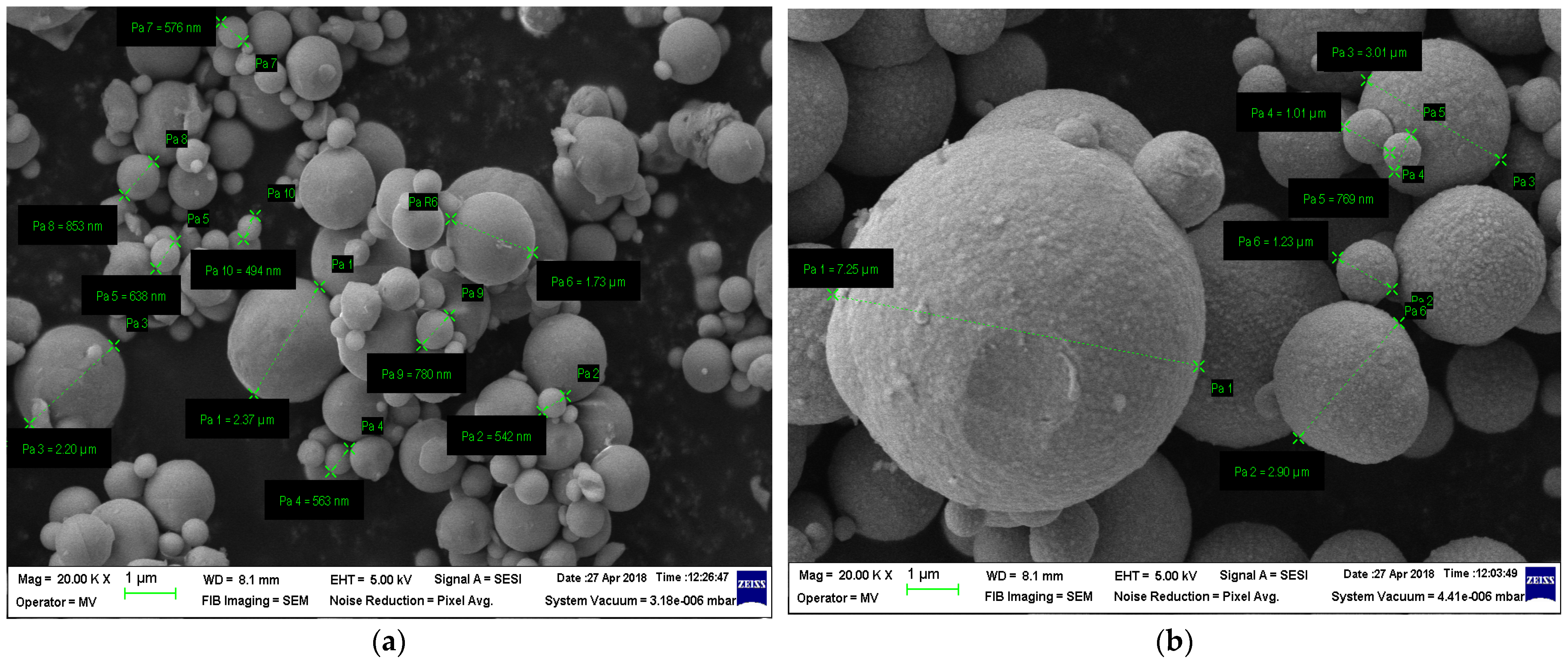
3.1. Structural Analyses

Figure 1 shows the micrographs, with the identification of the particle size, for the two powders used.
From the micrographs in Figure 1, a large dispersion of particle sizes is observed. This was highlighted by making 10 measurements of Al 800 nm powder particles, and the following values resulted: 2.37 μm, 542 nm, 638 nm, 1.73 μm, 576 nm, 853 nm, 780 nm and 494 nm. This powder has an average size of 798 nm. And in the case of Fe powder, the following values are obtained after six measurements: 7.25 µm, 2.9 µm, 3.01 µm, 1.01 µm, 769 nm, and 1.23 µm, for an average size of 2.78 µm.

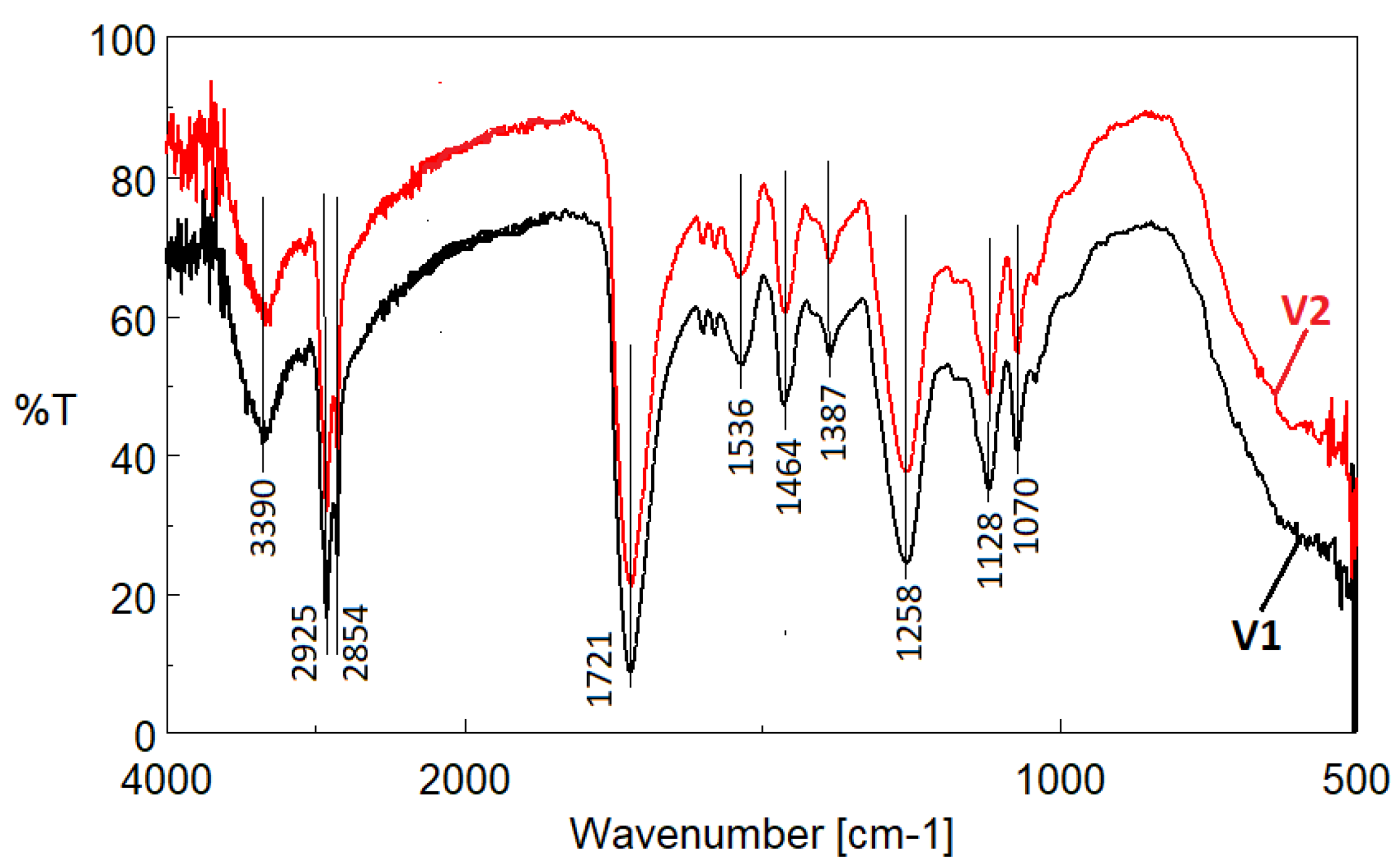
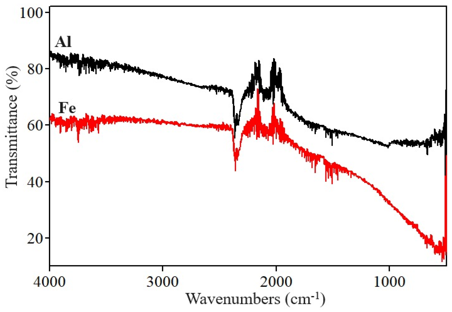
3.2. ATR/FTIR Analysis
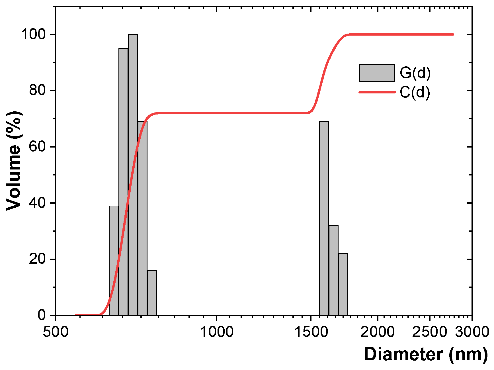
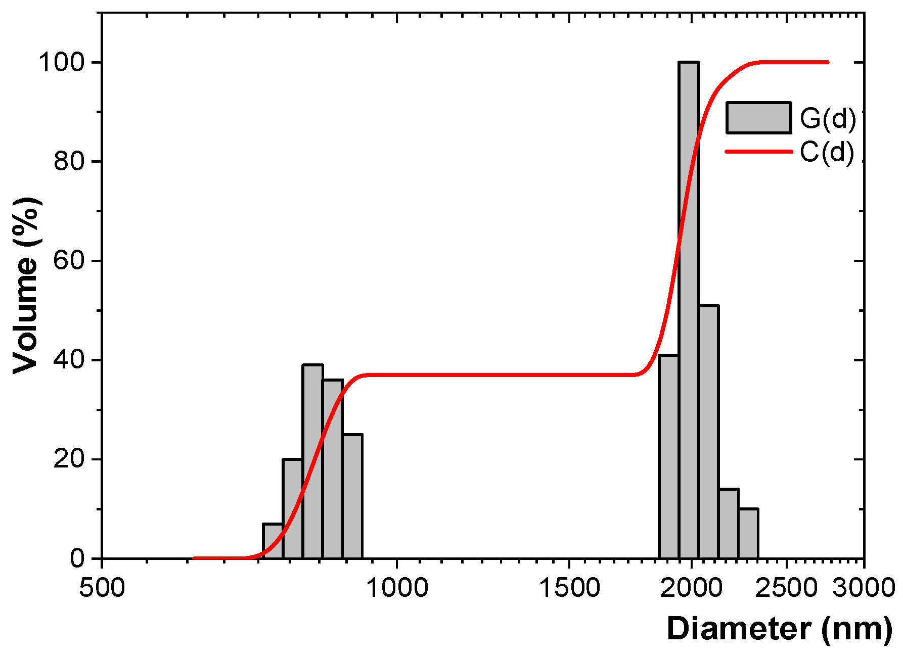
The ATR/FTIR spectra presented below were selected and reprocessed for the data presented in [20]. The ATR/FTIR spectra recorded on the two analyzed paint samples, before the metallic powder addition, is presented in Figure 2 (where V2 has a lower concentration of binder).
The spectral display absorption bands represent various functional groups present in the chemical composition of the samples being analyzed, as mentioned in references [20,21,22]: 3100–3600 cm−1, peaking around 3390 cm−1, specific to the stretching vibration of hydroxyl groups (–OH); 2700–3000 cm−1, specific to the stretching vibrations of the –CH-type groups; 2951 and 2925 cm−1 (CH3 asymmetric stretching vibration), 2854 cm−1 (for CH2 stretching vibration); 1610–1780 cm−1, the typical carbonyl group band, showing a primary peak at approximately 1721 cm−1 (resulting from the stretching vibration of the C–O group) and a faintly distinguishable peak at around 1715 cm−1 from the vibration of a ketone-type C=O, while 1500–1570 cm−1 has a peak around 1536 cm−1, specific to the C=O vibration; 1430–1500 cm−1, peaking at around 1464 cm−1, is caused by C–H bending vibrations (CH2, CH3); 1330–1420 cm−1, peaking at 1387 cm−1, indicates symmetrical deformation of CH2; 1258 cm−1 signifies characteristic C–O–C of ester type; 1000–1180 cm−1 displays multiple peaks (1040, 1070, and 1128 cm−1) characteristic for the vibration modes of C–O.
The characteristic features of acrylic-type compounds include the intense peak at 1258 cm−1 and the doublet at 1128 and 1170 cm−1 [23]. By comparing the data gathered, along with the information that bands within the ranges of 2700–3000 cm−1, 1610–1780 cm−1, 1430–1500 cm−1 are associated with methyl-methacrylate compounds [23], we can deduce that both types of paints studied are indeed acrylic in nature. However, it is clear that the ATR/FTIR spectra of both paint samples are nearly identical, indicating that the two paints being analyzed share the same fundamental chemical composition. Figure 3 shows ATR/FTIR spectra of metal powders, with notable peaks near the 2200 cm−1 band, yet all metallic powders are considered to be infrared-inactive substances. Finally, the comparative ATR/FTIR spectra recorded on V1 and V2 paints after the addition of metal fillers are presented in Figure 4.
Adding metal powders results in a significant alteration in the appearance of bands representing C=O groups in the 1610–1780 cm−1 region (band widens), as well as C–O–C at 1258 cm−1 (band widens and gains a multi-peaked structure). The intensity of the band characteristic of hydroxyl groups at 3390 cm−1 decreases with the presence of metal powder. The presence of electrostatic interactions between the acrylic matrix of the paint and the metal particles, potentially forming hydrogen bonds, contributes to this phenomenon [24]. The band specific for metallic particles identified in Figure 2 can be also identified in Figure 3. Regarding the transmittance level, the paints containing Al present a higher transmittance comparing to the paints containing Fe. On the other hand, it is obvious, for both paint types with metallic additives, that the transmittance decreases with the increase in the metallic particle content.

3.3. DLS Study

The results are presented in Figure 5 and Figure 6, and respectively in Table 1. G(d) represents the relative percentage contribution of the particle size range, and C(d) denotes the cumulated percentage contribution.
Both Al and Fe particles dispersed in aqueous suspensions at a concentration of 0.1 wt % revealed PDI values indicative of polydisperse particles (Table 1, Figure 5 and Figure 6). The PDI measures the width of the particle size distribution and is derived from the cumulants analysis of the DLS data.
The relative variance, a statistical measure used to describe the distribution of particle sizes within a sample, correlates with the PDI. It indicates the degree of polydispersity and how widely the particle sizes vary around the mean size (Table 1).
The mean and standard deviation of the hydrodynamic diameter were lower for Al particles (896.4 ± 35.6 nm) compared to Fe particles (1317.3 ± 71.4 nm). This indicates the coherence of the granulometric dimensions of the metallic powder-additive system within the binder and solvent. The Fe-based systems exhibited larger dispersion, a higher hydrodynamic diameter, and a larger mean diameter by volume compared to the Al systems. This observation is in agreement with the SEM analysis (Figure 1). Moreover, the particle size determined by DLS analysis is typically higher than that obtained by SEM or TEM analysis, as DLS considers the size of the inorganic particle core along with its surrounding adsorbed molecular layer from the aqueous suspension. Both Al and Fe particles dispersed in aqueous suspensions exhibited bimodal size distributions by volume. The Al particle suspension featured a predominant population of smaller particles (642.7–757.6 nm) with a C(d) of 9%–72%, and a second population of coarser particles (1587.4–1723.4 nm) with a C(d) of 88%–100% (Figure 5). In contrast, the Fe particle suspension had a first population of smaller particles (748.0–901.0 nm) with a C(d) of 2%–37%, and a dominant population of larger particles (1896.4–2284.1 nm) with a C(d) of 49%–100% (Figure 6).
The particle size distribution for Al particles was right-skewed, while that for Fe particles was left-skewed (Table 1), indicating deviations from a symmetrical distribution.
The bimodal characteristics of both Al and Fe particle size distributions can be attributed to the presence of both primary and agglomerated particles in the aqueous suspensions. However, no additional population of aggregates with higher particle sizes was observed in either suspension. Furthermore, deagglomeration of Al and Fe particles can be achieved through sonication or stirring, and the addition of additives within the binder and solvent prevented particle flocculation and sedimentation.

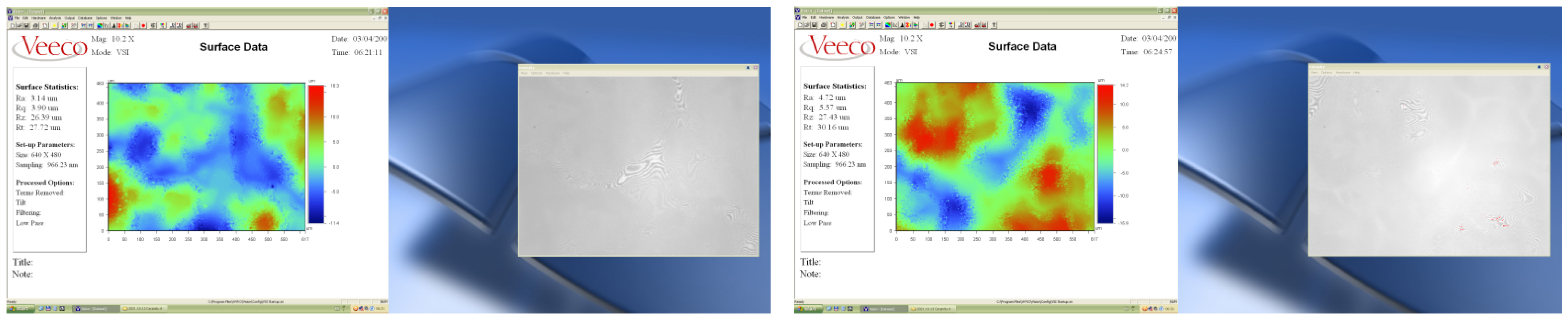
3.4. Determination of Thickness and Surface Topography (Roughness) of Paint Layers

The results are summarized in Table 2 and Figure 7 and Figure 8. The roughness of the paint layers with more metal particles content is about 30%–35% higher compared to the layers with less metal particle content, regardless the metal type. The roughness of the paint layers containing Al is at least 2.5 times higher compared to the paint layers containing Fe, an aspect which could be explained by a better formulation of paints containing Fe, in terms of dispersibility of metallic particles and/or affinity to the compatibilization additives, but also based on the granulometric results for the metallic systems.

3.5. Resistance to Water and Solvent (Isopropyl Alcohol)

The water/solvent (here isopropyl alcohol—specific for water-based paints) resistance of composite materials is determined by the amount of liquid that the material can absorb when immersed in water/solvent, according to SR EN ISO 175/2011 [25]. Approx. 0.1 g of each paint material was weighed and placed in plastic ampoules with tight lids (tubes for microcentrifuges with a diameter of 10 mm and a length of 40 mm). The ampoules with composite material were filled with deionized water and respectively with solvent (isopropyl alcohol) and then were kept for cycles of 72 h for a total duration of 360 h at a temperature of 22 °C (atmospheric) and an average humidity of 40%. The following Formula (1) was used to determine the resistance to the action of water/solvent (degree of swelling):
c = m 2 m 1 X m 1 × 100
where:
  • c—degree of swelling;
  • m2,3,4—mass of inflated/swollen material (after each 72-h cycle); X1—mass of initial—dry material.
The experimental results for the resistance to the action of water and the resistance to the action of alcohol are presented in Figure 9.
The hygroscopicity, as well as the dissolution in isopropyl alcohol, can be justified by the fact that the acrylic groups, existing in the paint, present functional groups that form hydrogen bonds with the water/alcohol they absorb. The dissolution occurs due to the fact that the solvent changes the spacing of the macromolecular chains and reduces intermolecular forces so much that a polymer solution is obtained.
Due to the higher inhomogeneity, and to the action of metallic particles mainly in the presence of water, the paints with a higher percent of metallic particles exhibited an expected higher swelling degree, but the value itself was remarkable high, i.e., the swelling degree of paints with 20% metallic powder was about 10 times higher than the one for the paints with 10% metallic powder. Regarding the influence of the type of added metal, the paints with Al present a higher swelling degree, at about 20%, compared to the paints with Fe. In all, the swelling degree seems to increase linearly with time in the case of water, but in the case of alcohol, it increases more rapidly in the first period, until 9 days of exposure, and then the increase is slower, due probably to the saturation of functional groups of the binder.

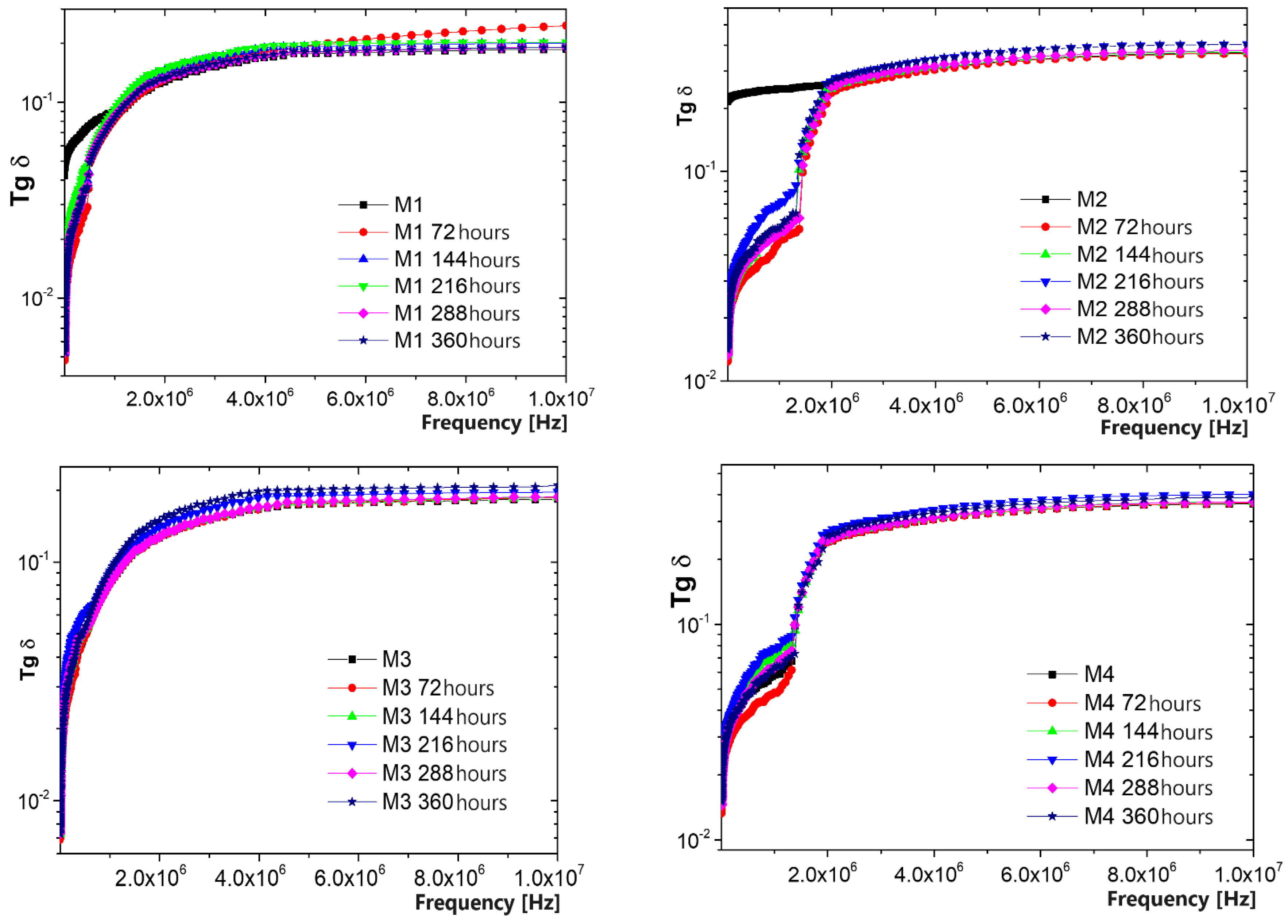
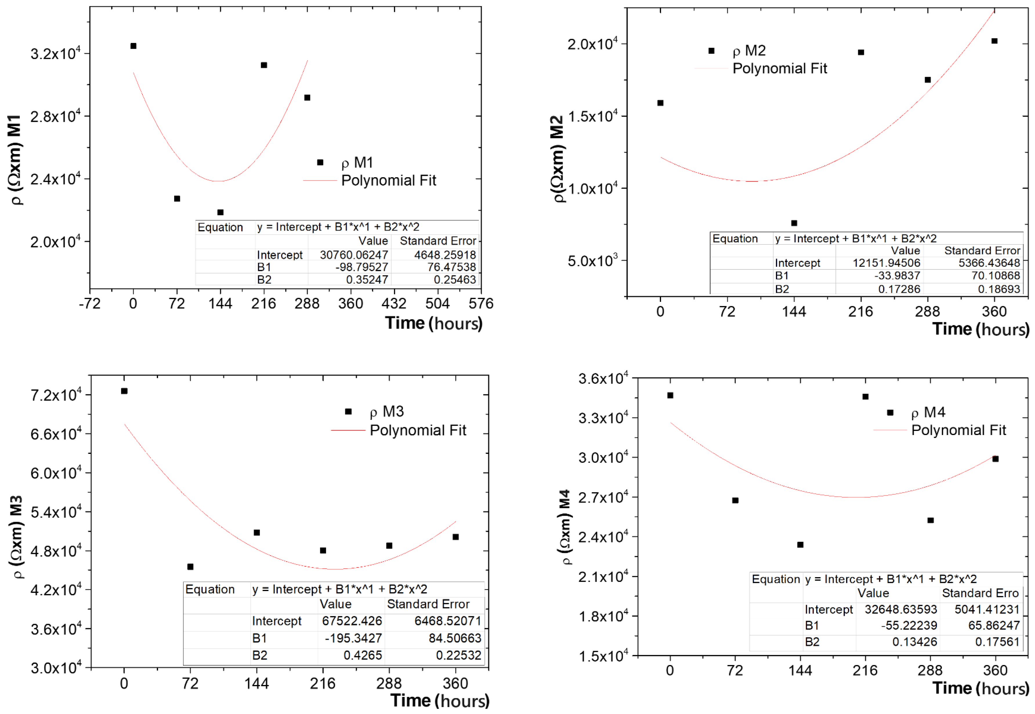
3.6. Resistance to the Action of UV Radiation and Lifetime Evaluation

The samples of paint films were subjected to exposure to UV radiation cycles of 72 h for a total duration of 360 h, according to ISO 4892-3:2016 [26,27].
It could be noticed that until 144 h of UV radiation exposure, the samples did not suffer any visible change; starting at 216 h, the samples M2 and M4 presented some micro-cracks, and after 288 h, the crack phenomenon intensified for all samples, leading to partial exfoliation from support after 360 h of exposure.
Due to the fact that for the proposed application of electromagnetic shielding, the main dielectric feature to be maintained was dielectric loss factor—Tg(Delta)—this was mainly analyzed, as presented in Figure 10.
When analyzing the initial values, it was noticed that the paint samples with higher metallic content present a higher loss factor, at about 20%, and a higher conductivity, about 10 times higher. The influence of metallic particles type is insignificant, even if the paints with Fe seem to present slightly higher values. Regarding the influence of exposure time, tg(Delta) presents a higher stability for all samples, even if some variations are noticed at lower frequencies, mainly for the paints with higher metallic content. The conductivity seems to be more affected by UV radiation, especially for the paints with higher metallic content. Here also the influence of metal type could be noticed, i.e., the conductivity of paints with Fe content is more sensitive to UV exposure compared to that of paints with Al content, meaning that Fe may catalyze some destruction processes at binder level.
On the other hand, some specific extra-polymerization phenomena under UV exposure were noticed, leading, e.g., to an increase in conductivity, mainly for M2 and M4, until 72 h of exposure, followed by the normal decrease after 144 h, a phenomenon in line with other related phenomena as in [26].
Finally, the estimated remaining lifetime was calculated, considering that the exposure to UV radiation continues, following the methodology in [27]. Here, the analyzed characteristic was the electrical resistivity (inverse of conductivity). The variation in the electrical resistivity according to the time of exposure to UV radiation is presented in Figure 11, and the functions that describe the trend of the variation curve were determined.
The critical value of the electrical resistivity at which the material can be considered to be degraded was chosen as a 30% variation from the initial value, and we could identify at what number of hours of UV radiation exposure the material should be replaced, i.e., M1 after 472 h, M2 after 360 h, M3 after 445 h, and M4 after 332 h, confirming the conclusions presented above, related to the higher stability of paints with lower metallic content, and respectively with Al insertions, but generally, the lifetime differences are not so high among the analyzed paints.

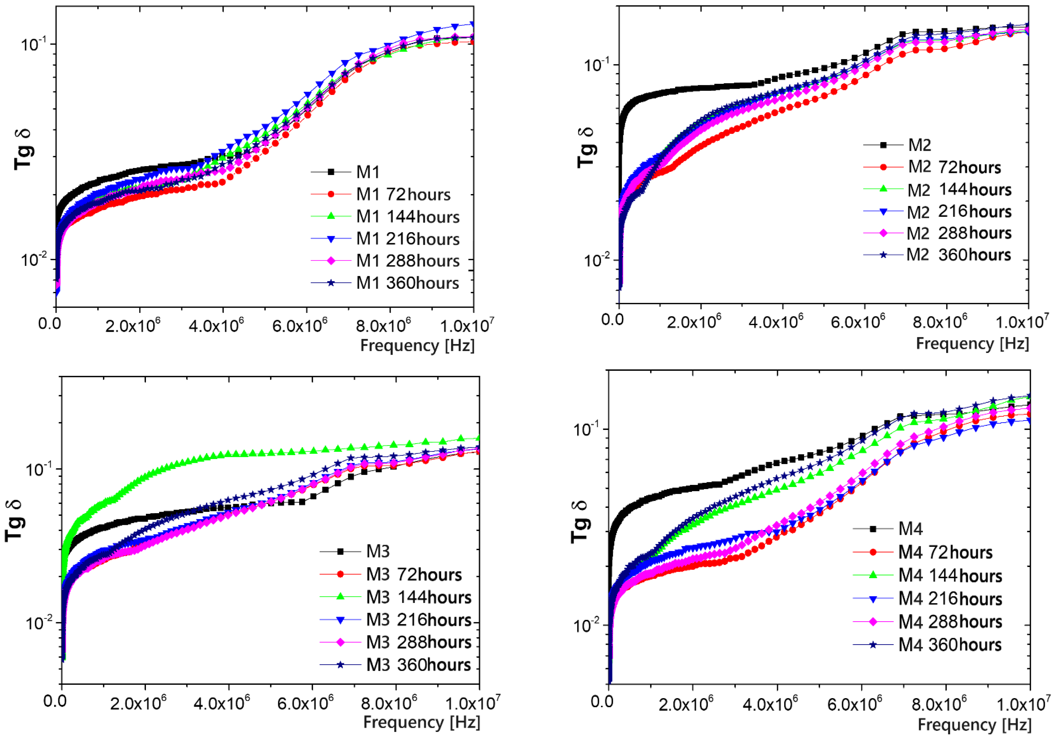
3.7. Resistance to the Action of Temperature and Lifetime Evaluation

The samples of paint films were placed in a Memmert UF30 oven with forced convection (Humeau, Couëron, France), at a temperature of 100 °C and maintained for cycles of 72 h for a total duration of 360 h, according to SR EN 60216-3:2007 [28,29]. The results for the investigated dielectric parameters are presented in Figure 12 and the lifetime evaluation in Figure 13.
It can be noticed that until 144 h of thermal exposure, the samples do not suffer any visible change, but starting at 216 h, the samples present visible yellow traces, which indicates that the binder is starting to be affected by the temperature. After 288 h, the crack phenomenon occurs for all samples, but no exfoliation process was identified, even after 360 h of exposure. It seems that the paints are more sensitive to long-time UV radiation exposure than to thermal exposure.
When analyzing the influence of exposure time, tg(Delta) presents a continuous decrease in value, mainly at lower frequencies, and a more pronounced decrease for the paints with higher metallic content. The conductivity seems to be very affected by the thermal exposure, with an unexpected high increase of values, especially after 144 h of exposure, and more pronounced for the paints with higher metallic content. Here also the influence of metal type could be noticed, i.e., the conductivity of paints with Al content is more sensitive to thermal exposure compared to that of paints with Fe content, meaning that in this case, Al is the main factor that may catalyze some destruction processes at the binder level.
Finally, the estimated remaining lifetime was calculated, considering that the thermal exposure continues, following the methodology in [29]. The variation in the electrical resistivity according to the time of thermal exposure is presented in Figure 13, and the functions that describe the trend of the variation curve were determined. The critical value of the electrical resistivity at which the material can be considered to be degraded was chosen as a 30% variation from the initial value, and we could identify at what number of hours of thermal exposure the material should be replaced, i.e., M1 after 562 h, M2 after 641 h, M3 after 447 h, and M4 after 476 h, confirming the conclusions presented above, related to the higher stability of paints with lower metallic content, and respectively with Fe insertions. The lifetime differences are not so high at higher metallic contents, but remain high enough at lower metallic contents when comparing the paints with Al and Fe.

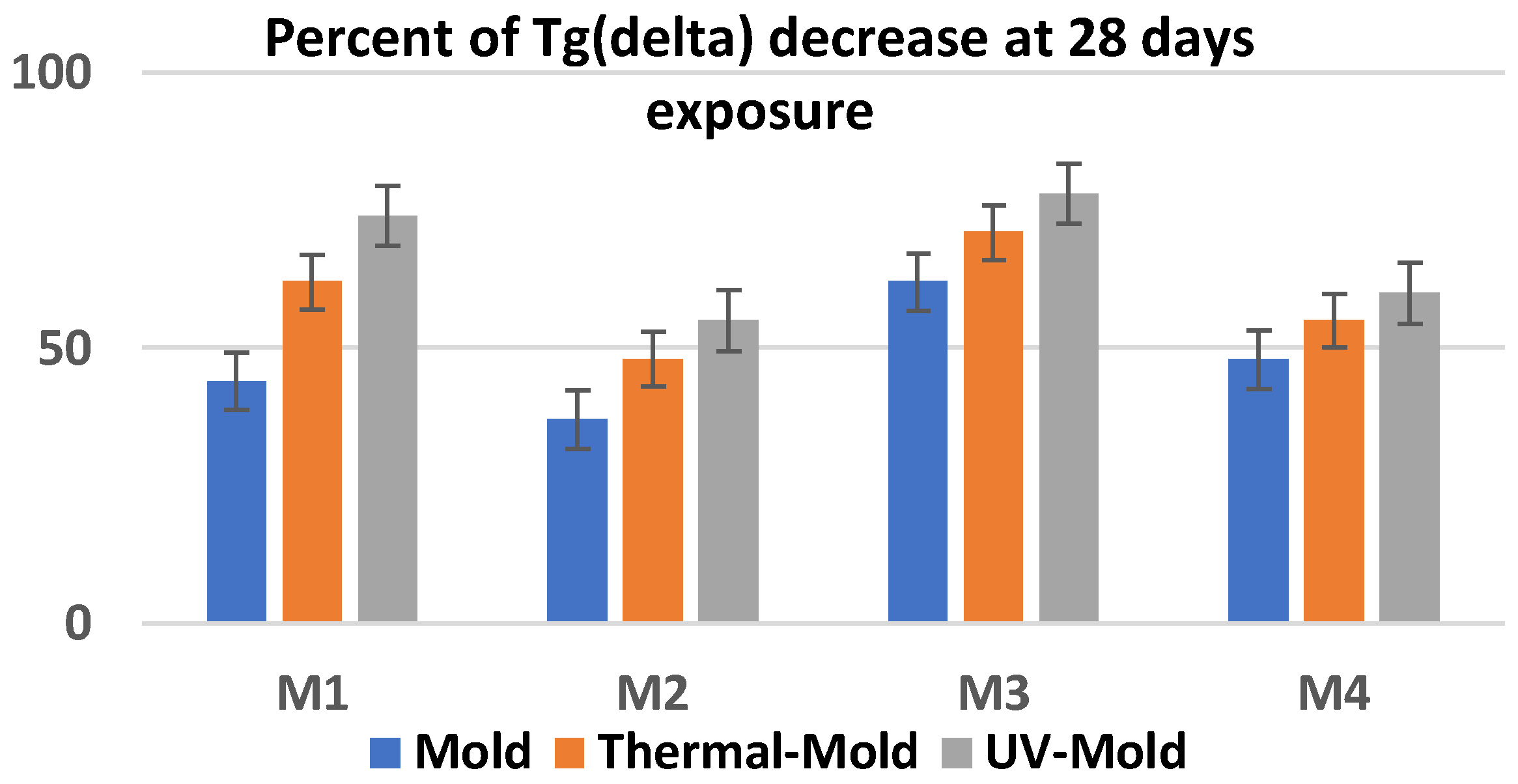
3.8. Resistance to the Action of Molds

The tests were performed according to EN 60068-2-10:2005 [30] and consisted in exposing the samples to the action of the fungal strains, in the presence of a nutrient medium (with sucrose as additional carbon source), in Petri dishes. The samples were applied to the agarized Czapek–Dox medium and inoculated by spraying with mixed spore suspensions (prepared in a nutrient solution of mineral salts). The tested molds were especially Trichoderma viride, Aspergillus flavus, and Aspergillus niger, the most aggressive species considered for the dedicated application of paints for electromagnetic shielding carcasses for automotive electronics. To ensure favorable conditions for spore germination and fungal development, the samples were incubated in a thermostat with humidification, at a temperature of 30 ± 2 °C and approximately 90% RH for 28 days.
The resistance to the action of molds was comparatively analyzed taking into account the initial paint samples and aged samples (thermal aging—1776 h in dry heat at 100 °C and then UV aged—432 h exposed to UV radiation of 100 W/m2), because the stabilization and destructive effect of molds may be enhanced on aged paint samples. In our case, the study was much more expanded comparing to homologue research results presented e.g., in [30,31].
The preliminary visual analysis upon the initial samples reveled that:
-
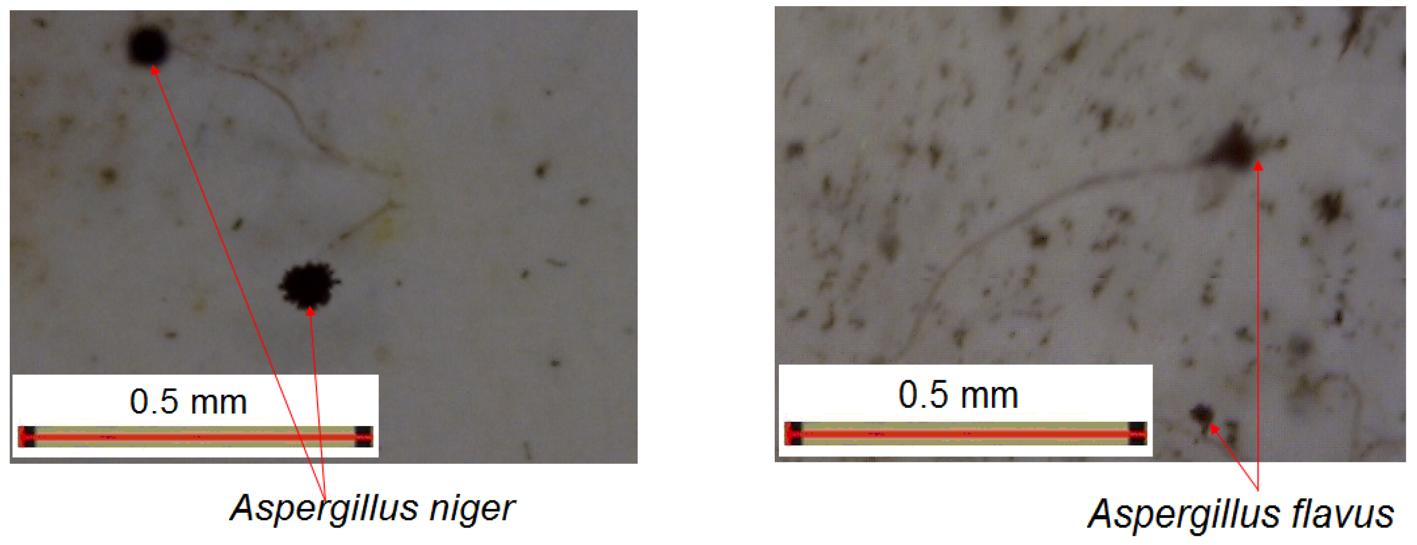
After 3 days of exposure, no zone of mold growth was observed on the paint samples, but a very dense growth of mold could be observed around the paint on the plastic sample support, and there were very few fungal colonies starting to penetrate the edge of the paint samples.
-
After 7 days of exposure, mold colonies were noticed on the samples, but they did not cover more than 20% of the sample surface, under the circumstances that massive mold colonies were growing around the paint samples.
-
After 14, 21, and 28 days of exposure, the mold colonies persisted on the paint samples, but they were found at the same stage of development as for 7 days, i.e., the degree of coverage remained unchanged at about 25% of the paint sample surface.
The maximum paint surface covering was noticed for M3 sample (25%), and the minimal effect for M2 (about 14%).
Taking into account homologous research upon acrylic paints [30], we can preliminarily estimate that the high content of metallic particles within the paints limits the extension of molds on paints, compared to homologue paints without metallic particle content, and the effect is remarkable, mostly because the added metallic particles are not from the classical category recognized for their anti-mold effect, such as Ag or Ni. On the other hand, the host and infestation area for mold activity remains the plastic support for paint deposition.
From the three mold types tested, only Aspergillus niger and Aspergillus flavus occurred on the paint surface, an example being indicated in Figure 14.
The similar observations upon paint samples thermally aged revealed that the results were similar to those for initial samples, i.e., after 28 days of exposure the mold colonies maintained on the paint samples do not cover more than 25% of the sample surface, even if massive mold colonies were growing around the paint samples.
When analyzing the UV-aged paint samples, some new aspects were revealed:
-
After 3 days of exposure, no large zones of mold growth were observed on the paint samples, but some few fungal punctual colonies were noticed, along with a very dense growth of mold observed around the paint samples and on the paint edges.
-
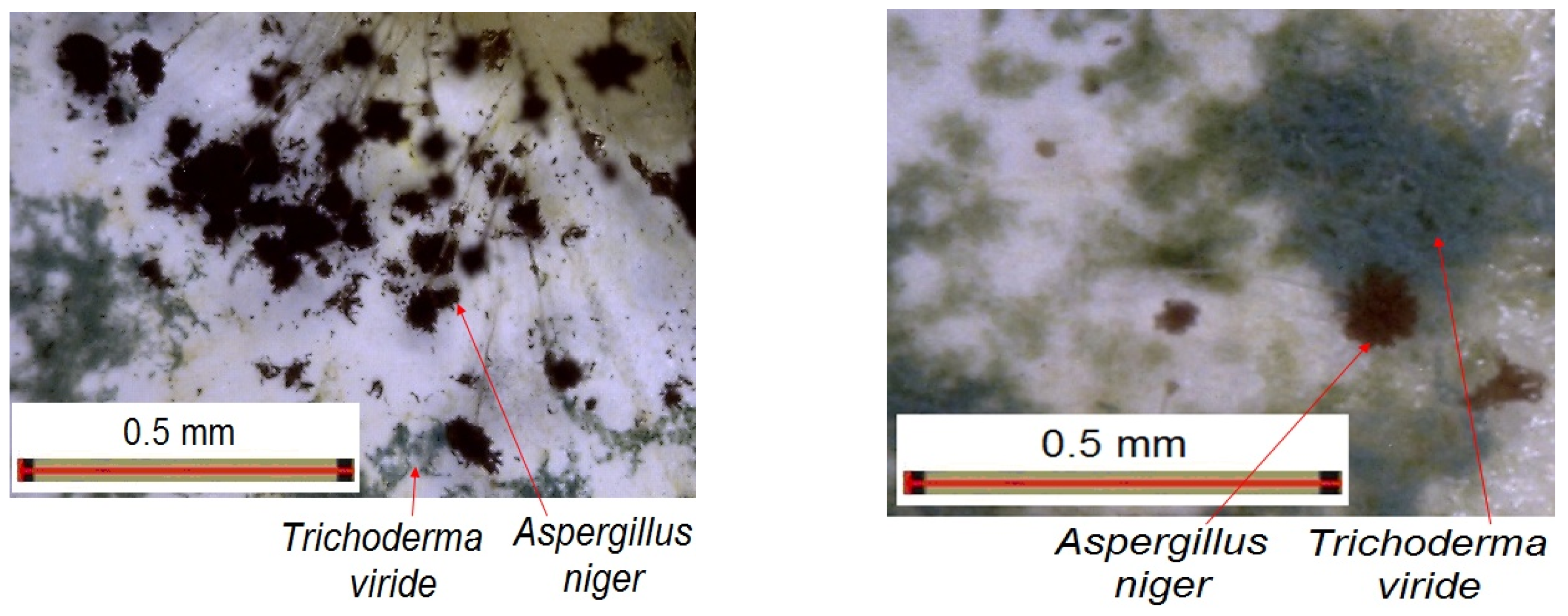
After 7 days of exposure, a consistent growth of fungal colonies on the paint samples were noticed, this time especially Trichoderma viride, mainly along with Aspergillus niger, exceeding 25% of the paint.
-
After 14, 21, and 28 days of exposure, the mold colonies were constantly developing upon the paint samples, but much more slowly, the degree of coverage remaining under 35% of the paint sample surface after 28 days, an example being indicated in Figure 15.
In this case, the maximum paint surface covering was noticed also for the M3 sample (over 35%), and the minimal effect for M2 (about 22%).
It is obvious that the UV aging effect is the most destructive also from the point of view of mold action. In order to assure a higher stability of paints, along with the limitation of the fungal effect, two strategies should be taken into account: addition of UV protection additives to the paint, and most relevant, addition of fungal protection additives within the plastic carcasses (the most sensitive to weathering conditions) which are supposed to be submitted to paint covering for electromagnetic shielding features. So the inhibition of molds at plastic surface is considered essential, because the mold action begins with a dense growth of mold around the paint on the plastic sample support, followed by a later penetration of the paint layer, forming the edge of the paint samples.
Taking into account that the most important characteristic of paint which assures the electromagnetic shielding features is the dielectric loss factor Tg(delta), the variation in this parameter was analyzed for combined cumulative action of molds, dry heat, and UV radiation. The results are presented in Figure 16.
It is obvious that the mold action significantly decreases the dielectric features of paints, when compared to the results under Section 3.6 and Section 3.7 for the aging of initial samples, but the weathering aging effect is much more enhanced if the samples are cumulatively submitted to thermal aging and then UV exposure, along with the mold action. The aging effect due to mold action is diminished for the paints with a higher metallic particle content, in all cases, even if those paints are more aged when exposed to thermal or UV aging alone. This aspect confirms synergetic effects of aging under thermal–mold and/or UV–mold action. The Tg(delta) factor diminishing is quite high, reaching about 80% for M1 and M3 under UV–mold exposure, M3 being, in fact, the most sensitive sample of all.
The conclusions for the weathering tests presented above are coherent with the ones presented in the literature for homologous coatings, e.g., [31,32,33], but in our case, the experiments emphasized with priority the evolution of dielectric parameters, which are the relevant parameters for the proposed application, and the remaining lifetime was predicted starting from these parameters, thus treating the material more as a polymeric insulation coating than a normal paint coating, which is a novelty in the domain.

4. Conclusions

This paper describes the innovative adaptation of some specific environmental tests from general organic coatings towards newly developed water-based composite paints with metallic particles (Al and Fe). The originality of the presented recipes lays in the fact that they include a high content of metal (10% and 20%) and special additives to allow them to offer high electromagnetic shielding features and high reliability on different plastic substrates.
Due to the higher inhomogeneity, and to the action of metallic particles mainly in the presence of water, the paints with a higher percent of metallic particles exhibit an expected higher swelling degree, but the value itself was remarkable high, i.e., the swelling degree of paints with 20% metallic powder was about 10 times higher than that of the paints with 10% metallic powder. Regarding the influence of the type of added metal, the paints with Al presented a higher swelling degree, at about 20%, compared to the paints with Fe.
The conductivity seems to be more affected by UV radiation, especially for the paints with higher metallic content. Here the influence of metal type could be noticed, i.e., the conductivity of paints with Fe content is more sensitive to UV exposure compared to that of paints with Al content, meaning that Fe may catalyze some destruction processes at the binder level.
The conductivity is also affected by the thermal exposure, with an unexpectedly high increase in values especially after 144 h of exposure, and more pronounced for the paints with higher metallic content. Here, the influence of metal type could be noticed, i.e., the conductivity of paints with Al content is more sensitive to thermal exposure compared to that of paints with Fe content, meaning that in this case, Al is the main factor that may catalyze some destruction processes at the binder level.
The resistance to the action of molds was comparatively analyzed taking into account the initial paint samples and aged samples (thermal aging—1776 h in dry heat at 100 °C and UV aged—432 h exposed to UV radiation of 100 W/m2), because the stabilization and destructive effect of molds may be enhanced on aged paint samples. The UV aging effect is more destructive from the point of view of mold action compared to thermal exposure. In order to assure a higher stability of paints, along with the limitation of fungus effect, two strategies should be taken into account: addition of UV protection additives to the paint, and most relevant, addition of fungal protection additives within the plastic carcasses which are supposed to be submitted to paint covering for electromagnetic shielding features. The mold action significantly decreases the dielectric features of paints, but the weathering aging effect is much more enhanced if the samples are cumulatively submitted to thermal aging and UV-exposure, along with the mold action. The aging effect due to mold action is diminished for the paints with higher metallic particles content, in all cases, even if those paints are more aged when exposed to thermal or UV aging alone. This aspect confirms synergetic effects of aging under thermal–mold and/or UV–molds action. The Tg(delta) factor diminishing is quite high, reaching about 80% for M1 and M3 under UV-mold exposure, M3 being in fact the most sensitive sample of all. Because molds have a significant impact on the dielectric properties of paints, it is advisable to use a mold inhibitor. However, it should be compatible with the neutral pH of water-based paints. For instance, adding 0.2%–0.3% of Dryzone® ACS [34] is recommended, but further testing is necessary before demonstrating it in an operational environment.
The potential application of this study is related mainly in the development of new autonomous electric cars, which need special conditions of electromagnetic shielding, to avoid interference and protect the large quantity of sensors and IoT-related devices, but the electromagnetic shielding efficiency assured by layers of conductive paints is normally very sensitive to environmental factors, leading to the deterioration of the paint layers and so affecting the equipment performance and security.

Author Contributions

Conceptualization, A.R.C. and R.C.C.; methodology, R.C.C., M.A., M.V.L., N.O.N. and E.M.L.; validation, R.C.C. and M.A.; formal analysis, A.R.C., R.C.C. and M.A.; investigation, A.R.C., R.C.C., M.A., M.V.L., N.O.N. and E.M.L.; data curation, R.C.C., M.A. and A.R.C.; writing—original draft preparation A.R.C. and R.C.C.; writing—review and editing, R.C.C. and M.A.; visualization, R.C.C. and A.R.C.; supervision, M.V.L. and R.C.C. All authors have read and agreed to the published version of the manuscript.

Funding

This research received no external funding.

Institutional Review Board Statement

Not applicable.

Informed Consent Statement

Not applicable.

Data Availability Statement

The data presented in this study are available on request from the corresponding author.

Acknowledgments

The research presented in this paper represents a partial dissemination of the results achieved within the following grants: 1. Nanostructured paints and primers with electromagnetic shielding properties, with impact in the field of automotive components, 298/30.06.2020, SMIS 120155; 2. PNCDI III, Program 1/Project number PN23140201-42N/2023, beneficiary National Institute for Research and Development in Electrical Engineering ICPE—CA Bucharest.

Conflicts of Interest

The authors declare no conflicts of interest.

References

  1. EMC Electrically Conductive Paints. Available online: https://www.solianiemc.com/en/cp/emc-electrically-conductive-paints/?gad_source=1&gclid=Cj0KCQjwjLGyBhCYARIsAPqTz1-DOF1Sw7J8wFzhbDIZLBd4b8Z5UxsiopHr2oeQ_mM4k1MuQkk-btgaAsFvEALw_wcB (accessed on 30 May 2024).
  2. EMF and RFI Shielding with Conductive Paints. Available online: https://www.antala.uk/emf-and-rfi-shielding-with-conductive-paints/ (accessed on 30 May 2024).
  3. Conductive Paints and Coatings. Available online: https://limitless-shielding.com/conductive-paints-and-coatings/ (accessed on 30 May 2024).
  4. ECOS Paints. Available online: https://ecospaints.net/blog/what-to-know-about-electromagnetic-shielding-materials (accessed on 30 May 2024).
  5. Conductive Translucent Paint. Available online: https://hollandshielding.com/en/conductive-translucent-paint?gad_source=1&gclid=CjwKCAjw9cCyBhBzEiwAJTUWNZC2A5l8HgsLs4KaJrIJbPz6e8rSoxmem-6Wv9nuq7kMi8Koz6ZhDhoCCHAQAvD_BwE (accessed on 30 May 2024).
  6. Conductive Paints. Available online: https://mgchemicals.com/category/conductive-paint/ (accessed on 30 May 2024).
  7. Electric Paint. Available online: https://www.bareconductive.com/collections/electric-paint (accessed on 30 May 2024).
  8. Electrically Conductive Paints. Available online: https://www.euro-technologies.eu/en/product/electrically-conductive-paints/ (accessed on 30 May 2024).
  9. Reflective Paint: A Low-Tech Solution for Sustainable Cooling in Buildings. Available online: https://www.neto-innovation.com/post/reflective-paint-a-low-tech-solution-for-sustainable-cooling-in-buildings (accessed on 30 May 2024).
  10. Merino, G.; Celeste, M. Synthesis and characterization of Co3O4 nanoparticles for use as pigments in solar absorbing paints. GSC Adv. Eng. Technol. 2021, 1, 7–20. [Google Scholar] [CrossRef]
  11. Gunde, M.K.; Orel, Z.C. Absorption and scattering of light by pigment particles in solar-absorbing paints. Appl. Opt. 2000, 39, 622–628. [Google Scholar] [CrossRef] [PubMed]
  12. Coser, E. Development of paints with infrared radiation reflective properties. Polímeros 2015, 25, 305–310. [Google Scholar] [CrossRef]
  13. Joglekar-Athavale, A. Solar absorptive coating: A thermally stable spinel pigment based coating with inorganic binder for waterborne paint. Pigment. Resin Technol. 2021, 50, 302–308. [Google Scholar] [CrossRef]
  14. Kamjunk, N.; Spohn, U.; Morig, C.; Wagner, G. A Test Device for Microalgal Antifouling Using Fluctuating pH Values on Conductive Paints. Water 2020, 12, 1597. [Google Scholar] [CrossRef]
  15. Miszczyk, A.; Darowicki, K. Effect of environmental temperature variations on protective properties of organic coatings. Prog. Org. Coat. 2003, 46, 49–54. [Google Scholar] [CrossRef]
  16. Miszczyk, A.; Darowicki, K. Accelerated aging of organic coating systems by thermal treatment. Corros Sci. 2001, 43, 1337–1343. [Google Scholar] [CrossRef]
  17. Fedrizzi, L.; Bergo, A.; Deflorian, F.; Valentinelli, L. Assessment of protective properties of organic coatings by thermal cycling. Prog. Org. Coat. 2003, 48, 271–280. [Google Scholar] [CrossRef]
  18. Ciobanu, R.; Spohn, U.; Morig, C.; Wagner, G.; Neu, T.R. Composite Paints with High Content of Metallic Microparticles for Electromagnetic Shielding Purposes. Coatings 2024, 14, 874. [Google Scholar] [CrossRef]
  19. Caramitu, A.R.; Mitrea, S.; Marinescu, V.; Ursan, G.A.; Aradoaie, M.; Lingvay, I. Dielectric Behavior and Morphostructural Characteristics of Some HDPE Composites /Metal Nanopowders. Mater. Plast. 2019, 56, 103–109. [Google Scholar] [CrossRef]
  20. Caramitu, A.; Ion, I.; Bors, A.M.; Ciobanu, C.R.; Schreiner, C.; Aradoaei, M.; Caramitu, A.M.D. Physico-chemical Characterization of Paint Films with Electromagnetic Properties. Mater. Plast. 2022, 59, 9–23. [Google Scholar] [CrossRef]
  21. Mancini, D.; Percot, A.; Bellot-Gurlet, L.; Colomban, P.; Carnazza, P. On-site contactless surface analysis of Modern paintings from Galleria Nazionale (Rome) by Reflectance FTIR and Raman spectroscopies. Talanta 2021, 227, 122159. [Google Scholar] [CrossRef] [PubMed]
  22. Hayes, P.A.; Vahur, S.; Leito, I. ATR-FTIR spectroscopy and quantitative multivariate analysis of paints and coating materials. Spectrochim. Acta Part A Mol. Biomol. Spectrosc. 2014, 133, 207–213. [Google Scholar] [CrossRef] [PubMed]
  23. Ortiz-Herrero, L.; Cardaba, I.; Setien, S.; Bartolomé, L.; Alonso, M.L.; Maguregui, M.I. OPLS multivariate regression of FTIR-ATR spectra of acrylic paints for age estimation in contemporary artworks. Talanta 2019, 205, 120114. [Google Scholar] [CrossRef] [PubMed]
  24. Hamada, I.; Kumagai, T.; Shiotari, A.; Okuyama, H.; Hatta, S.; Aruga, T. Nature of hydrogen bonding in hydroxyl groups on a metal surface. Phys. Rev. B 2012, 86, 075432. [Google Scholar] [CrossRef]
  25. SR EN ISO 175/2011; Plastics—Methods of Test for the Determination of the Effects of Immersion in Liquid Chemicals. ISO: Geneva, Switzerland. Available online: https://e-standard.eu/en/standard/186982 (accessed on 30 May 2024).
  26. ISO 4892-3:2016; Plastics—Methods of Exposure to Laboratory Light Sources, Part 3: Fluorescent UV Lamps. ISO: Geneva, Switzerland. Available online: https://www.iso.org/standard/67793.html (accessed on 30 May 2024).
  27. Aguilar-Rodríguez, P.; Mejía-González, A.; Zetina, S.; Colin-Molina, A.; Rodríguez-Molina, B.; Esturau-Escofet, N. Unexpected behavior of commercial artists’ acrylic paints under UVA artificial aging. Microchem. J. 2021, 160, 105743. [Google Scholar] [CrossRef]
  28. van der Weijde, D.H.; van Westing, E.P.M.; Ferrari, G.M.; de Wit, J.H.W. Lifetime Prediction of Organic Coatings with Impedance Spectroscopy. Polym. Mater. Sci. Eng. 1996, 74, 12–16. [Google Scholar]
  29. SR EN 60216-3:2007; Electroinsulating Materials. Thermal Endurance Properties. Part 3: INSTRUCTIONS for the Calculation of Thermal Endurance Characteristics. ISO: Geneva, Switzerland. Available online: https://magazin.asro.ro/ro/standard/117649 (accessed on 30 May 2024).
  30. IEC 60068-2-10:2005; Environmental Testing—Part 2-10: Tests—Test J and Guidance: Mould Growth. IEC: London, UK. Available online: https://standards.iteh.ai/catalog/standards/clc/d098bcec-f96d-46df-9495-300001cf8218/en-60068-2-10-2005 (accessed on 30 May 2024).
  31. Caramitu, A.; Butoi, N.; Rus, T.; Luchian, A.M.; Mitrea, S. The Resistance to the Action of Molds of Some Painting Materials Aged by Thermal Cycling and Exposed to an Electrical Field of 50 Hz. Mat. Plast. 2017, 54, 331–337. [Google Scholar] [CrossRef]
  32. Iscen, A.; Forero-Martinez, N.; Valsson, O.; Kremer, K. Acrylic Paints: An Atomistic View of Polymer Structure and Effects of Environmental Pollutants. J. Phys. Chem. B 2021, 125, 10854–10865. [Google Scholar] [CrossRef] [PubMed]
  33. Cogulet, A.; Blanchet, P.; Landry, V. Evaluation of the Impacts of Four Weathering Methods on Two Acrylic Paints: Showcasing Distinctions and Particularities. Coatings 2019, 9, 121. [Google Scholar] [CrossRef]
  34. Available online: https://safeguardstore.co.uk/dryzone-acs-anti-mould-paint-additive/ (accessed on 30 July 2024).
Figure 1. SEM micrographs for (a) Al powder 800 nm and for (b) Fe powder 790 nm [19].
Coatings 14 01016 g001
Figure 2. ATR/FTIR spectra recorded before metallic powder addition [20].
Coatings 14 01016 g002
Figure 3. Comparative ATR/FTIR spectra recorded on metal powders [20].
Coatings 14 01016 g003
Figure 4. Comparative ATR/FTIR spectra recorded on paints with different metal fillers [20].
Coatings 14 01016 g004
Figure 5. Particle size distribution histogram (MSD) of Al particles by volume.
Coatings 14 01016 g005
Figure 6. Particle size distribution histogram (MSD) of Fe particles by volume.
Coatings 14 01016 g006
Figure 7. Roughness analysis for M1 and M2.
Coatings 14 01016 g007
Figure 8. Roughness analysis for M3 and M4.
Coatings 14 01016 g008
Figure 9. Resistance to the action of (a) water, (b) isopropyl alcohol.
Coatings 14 01016 g009
Figure 10. Tg(Delta) variation vs. time at UV radiation exposure.
Coatings 14 01016 g010
Figure 11. Lifetime evaluation results for UV radiation exposure.
Coatings 14 01016 g011
Figure 12. Tg(Delta) variation vs. time at thermal exposure.
Coatings 14 01016 g012
Figure 13. Lifetime evaluation results for thermal exposure.
Coatings 14 01016 g013
Figure 14. Molds occurrence on M2, after 7 days of exposure [30].
Coatings 14 01016 g014
Figure 15. Mold occurrence on M3, after 7 days and, respectively, 28 days of exposure [30].
Coatings 14 01016 g015
Figure 16. Tg(delta) variation at combined action of molds, dry heat, and UV radiation.
Coatings 14 01016 g016
Table 1. DLS results for Al and Fe particles dispersed in aqueous suspensions at a concentration of 0.1 wt %.
SampleHydrodynamic
Diameter
(nm)
Polydispersity
Index (PDI)
MSD by Volume
Mean Diameter
(nm)
Relative
Variance
Skew
Al particles896.4 ± 35.60.113 ± 0.058951.40.1960.999
Fe particles1317.3 ± 71.40.126 ± 0.0221580.50.133−0.484
Table 2. Average surface roughness of paint layers.
Roughness (µm)Thickness of Paint Layer (µm)RaRqRt
M119.962.953.7325.65
M225.873.784.8230.16
M320.491.011.258.39
M426.201.341.6610.91
Disclaimer/Publisher’s Note: The statements, opinions and data contained in all publications are solely those of the individual author(s) and contributor(s) and not of MDPI and/or the editor(s). MDPI and/or the editor(s) disclaim responsibility for any injury to people or property resulting from any ideas, methods, instructions or products referred to in the content.

