Abstract
With the growing interest in additive manufacturing technology, assessing the biocompatibility of manufactured elements for medical and veterinary applications has become crucial. This study aimed to investigate the corrosion properties and cytotoxicity of porous structures designed to enhance the osseointegration potential of implant surfaces. The structures were fabricated using BJ technology from 316L stainless steel powder, and their surfaces were modified with a DLC coating. The studies carried out on porous metal samples with and without DLC coatings demonstrated low cytotoxicity. However, no significant differences were found between the uncoated and DLC-coated samples, likely due to variations in the thickness of the coating on the porous samples and the occurrence of mechanical damage.
1. Introduction
Additive manufacturing, with its potential to produce components with complex geometries from a wide range of materials, has found applications in many fields, including medicine and veterinary science [1,2]. The development of additive manufacturing technology has resulted in many interesting solutions. Particularly promising is the concept of manufacturing porous bone implants with mechanical properties tailored to the replaced bone tissue. This approach aims to counteract the phenomenon of stress shielding by reducing the stiffness of the implants [3,4]. Additionally, the porous structure of the implant promotes osteointegration and neovascularization processes [5,6]. The large specific surface area supports cell migration and adhesion, and the open interconnected pore system ensures the flow of nutrients and oxygen [7]. Surface roughness also plays an important role in the osteointegration process [8,9].
In the initial phase of research on porous bone implants, the focus was primarily on simple constructions based on lattice structures [10,11]. The greatest advantage of these structures is their simple and easy-to-replicate design. However, the connections between the elements of these structures (so-called struts) serve as stress concentration points [12], resulting in an undesirable deformation model from a biomedical application perspective [13,14]. Moreover, non-stochastic lattice structures do not fully mimic the irregular structure of bone tissue. Consequently, increasing attention has been directed towards the use of irregular structures based on Voronoi tessellation [15,16,17,18] and structures based on Triply Periodic Minimal Surface topologies [19,20,21,22]. Technologies such as Powder Bed Fusion and binder jetting, which use metal powders as the construction material, are used to produce porous structures for bone tissue regeneration applications.
From a medical application perspective, the biocompatibility of the material is of the utmost importance. The material introduced into the body must not induce inflammatory reactions and not be toxic to living cells and organisms [23,24]. For metallic materials, corrosion caused by the aggressive environment of body fluids poses a significant risk [25,26]. This phenomenon can lead to the release of metal ions into the body, which may cause inflammatory reactions, metallosis, and, in the long term, even cancer [27,28,29,30]. A well-known method for protecting implant surfaces from corrosion is the modification of their surfaces by depositing a coating or surface texturing [31,32]. DLC coatings have biomedical applications, and, therefore, research on their biocompatibility is important [33]. Numerous studies confirm that Diamond-Like Carbon (DLC) coatings can be used to create a diffusion protective coating on the surface of metal implants. DLC coating contains two main phases: a diamond phase with the σsp3 hybridization of carbon atoms, and an amorphous phase with the σsp2 hybridization of carbon atoms [34]. Biological tests of carbon-based materials, including diamonds and graphite nanoparticles, allow for the determination of their biological properties [35] and biological activity, e.g., cytotoxicity assessment [36], with respect to DLC coatings.
This is due to the crystallographic structure of the DLC coating, which is a mixture of diamond and graphite and a very small amount of carbyne. They have a lot of interesting advantages, for example, having high stability in corrosive media and being chemically inert, optically transparent, and also biocompatible. The DLC coating is a mixture that contains approximately 60% graphite, 30% diamond and 10% other allotropic forms of carbon [37]. The characteristics of Ramn spectroscopy allow for the identification of the diamond phase and the so-called amorphous phase (amorphous carbon), which is usually graphite. Chemically, we are dealing with carbon, but with a clearly marked crystallographic structure that determines the properties of this material [38].
Diamonds that do not show cytotoxicity can be used in regenerative medicine and tissue engineering as nano-scaffolds [39]. There are literature reports extensively discussing the effect of nanodiamonds on vascular endothelial cells. This is due to the fact that endothelial cells are associated with oxidative stress and are very sensitive to changes in oxydo-reduction potential, while nanodiamonds have a strong antioxidant effect [40]. The cytotoxic effects of diamond are very slightly marked because this allotropic form of carbon does not show a significant cytotoxic effect in tests on cell lines [40,41]. Additionally, the metal implants, for example, the metallic materials in jewellery, may cause allergies, so a natural solution is to look for a biocompatible or, rather, bioactive biomaterial to cover them. Also, the use of body piercings covered by DLC coatings provides significant protection against inflammatory, allergic, and carcinogenic processes. At this point, the diamond coatings on metal implants have a very positive effect on the human body [42]. But this strong effect has been tested on an extended surface, i.e., diamond nanoparticle in vivo tests. This study was also designed to examine the effect of nanodiamonds on the phagocytosis activity and oxidative burst of innate immune cells. When describing the research results, it should be underlined that nanodiamonds play a key role in oxidation–reduction mechanisms in inhibiting oxidative stress and do not have cytotoxic or immunological effects [43]. Moreover, the nanodiamonds have an apoptotic effect, protect against cancer, and induce cell death [44].
Depending on the type, size, and concentration of carbon nanoparticles, combined treatments with other drugs have observed the intensification of the degree of cytotoxicity, especially in terms of the apoptosis of cells and cancer cells. Carbon-based nanomaterials are promising in the prevention and treatment of cancer cells [45,46].
Figure 1 shows the potential application of carbon nanomaterials. Since the mammalians cells can switch to other pathways more flexibly than bacterial cells under the disturbance of the same metabolism pathway inhibition, the metal-containing carbon dots provide excellent biocompatibility, in addition to their bactericidal effect. In ecotoxicological research, CO2 enhanced the aggregation of carbon dots derived from beetroot, which is consistent with the carbon dot characteristics of increased fluorescence intensity, decreased nanozyme activity, and decreased toxicity to bacteria and cancer cells, but enhanced fluorescence in cells, which can be applied for bioimaging or CO2 sensing. The research results confirm the low cytotoxicity of carbon-based biomaterials; however, their antioxidant and anti-carcinogenic properties and weak bactericidal effects should be noted [45,46].
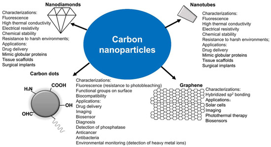
Figure 1.
Types of carbon nanoparticles with their characterizations and applications, used with permission of the authors of [45].
The aim of this study was to investigate the corrosion properties and cytotoxicity of porous structures designed to enhance the osseointegration potential of implant surfaces. The structures were manufactured using BJ technology from 316L stainless steel powder, and their surfaces were modified with a DLC coating.
2. Materials and Methods
2.1. Sample Fabrication
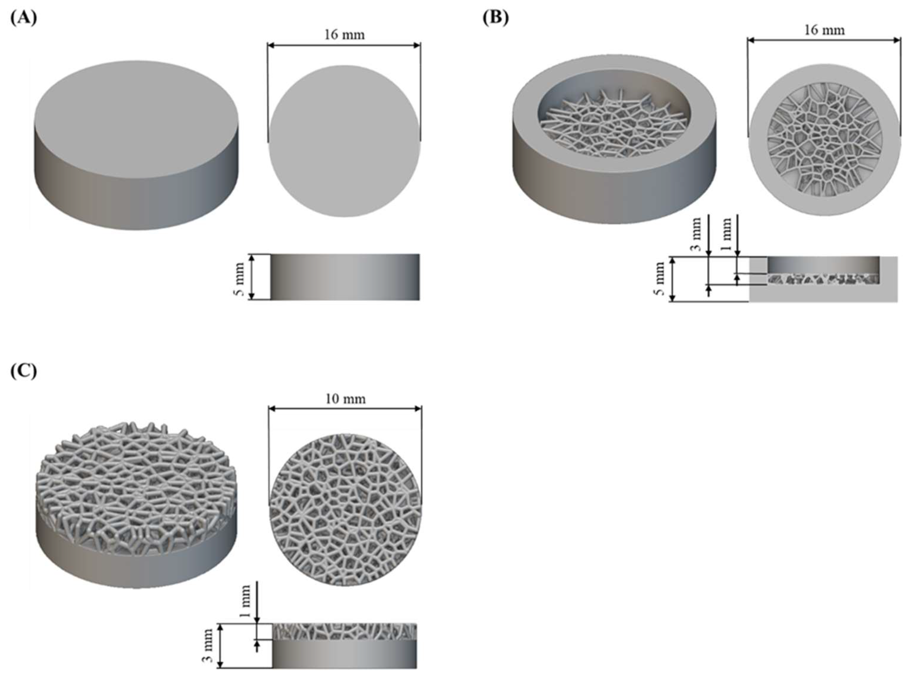
The research was carried out on flat substrates and substrates with a porous structure designed based on Voronoi tessellation (Figure 2). nTopology software (nTopology 4.24.3, New York, NY, USA) [47] was used to design the porous structure, according to the methodology described in Laskowska et al. [48]. The substrates were in the shape of cylinders with a diameter of 16 mm and a height of 5 mm for samples for electrochemical corrosion tests, and with a diameter of 10 mm and a height of 3 mm for cytotoxicity tests. The designed diameter of the structures in the porous structure was 0.3 mm.
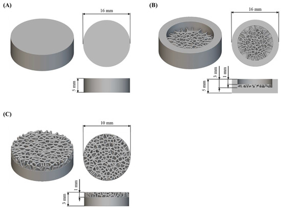
Figure 2.
CAD models and geometrical dimension of tested substrates to (A,B) electrochemical corrosion tests and (C) cytotoxicity tests.
The substrates were fabricated using binder jetting technology using an ExOne Innovent+ (ExOne, Huntington, PA, USA) from stainless steel 316L powder (Sandvik Osprey, Neath, UK). In this technology, the component is created by applying a liquid binding agent (the so-called binder) to a selected surface of the powder layer based on a CAD model. The manufacturing process involves several stages: the layer-by-layer construction of the component, binder curing, depowdering, high-temperature sintering, and post processing (if necessary) [49,50]. The main manufacturing parameters of the binder jetting process used to produce the tested substrates are presented in Table 1.

Table 1.
Manufacturing parameters of the binder jetting process.
The binder curing step was carried out for 8 h at 200 °C in a DX412C convection oven (Yamato Scientific, Tokyo, Japan). Excess powder was removed by gentle brushing and using a stream of compressed air. The final stage was high-temperature sintering in an argon atmosphere in a Nabertherm furnace (Nabertherm, Lilienthal, Germany), according to the methodology described in detail in Laskowska et al. [48].
After fabrication, the substrates were cleaned using compressed air and ultrasonically washed in distilled water (10 min) to remove trapped powder particles and other contaminants. The surface of some flat samples was mechanically polished using diamond paste with a grain size of 3 µm.
2.2. DLC Coating Deposition
The deposition of the DLC coating was preceded by an ion etching process, which aimed to properly prepare the surface by cleaning and heating it. A DLC coating was deposited on the surface of the substrates using RF PACVD technology (Łódź University of Technology, Łódź, Poland). The samples were placed directly on the RF electrode. The parameters of the ion etching process and the DLC coating deposition are summarized in Table 2.
Table 2.
Ion pre-treatment and DLC coating deposition process parameters, based on Laskowska et al. [48].
2.3. Scaning Electron Microscopy
The substrate surface morphology was analyzed using a scanning electron microscope, PHENOM PRO (Thermo Fisher, Waltham, MA, USA). SEM microscopy, using ZEISS Ultra Plus (ZEISS, Oberkochen, Germany), was also performed on cross-sections of substrates with a porous structure after the deposition of the DLC coating to analyze the thickness and continuity of the DLC coating. The cross-sections were prepared using the methodology described in Laskowska et al. [48].
2.4. Electrochemical Corrosion
The preparation of samples for electrochemical corrosion testing included ultrasonic washing in distilled water (10 min), and then in isopropanol (5 min). Table 3 presents a summary of the substrates used for electrochemical corrosion testing along with their labels and descriptions. The reference point for comparative analysis for the samples before surface modification with a DLC coating was a traditionally manufactured 316L stainless steel sample with a polished surface (designated as AISI316L_polished).
Table 3.
Substrates used for electrochemical corrosion testing.
The electrochemical corrosion tests were conducted in a 0.9% saline solution, obtained by dissolving 8 g of NaCl in 1.0 L of distilled water. The solution was maintained at a temperature of 37 °C, and its degassing was achieved by argon throughout all corrosion tests. A three-electrode electrochemical cell (400 mL Corrosion Cell, Methrom Autolab B.V., Utrecht, The Netherlands), with a platinum rod as a counter electrode, a saturated calomel electrode (SCE, Elmetron, Zabrze, Poland) as the reference electrode, and the tested sample as the working electrode, was used. An Autolab PGSTAT 302N potentiostat operated using NOVA 1.11 software (Metrohm Autolab B.V., Utrecht, The Netherlands) was used for electrochemical measurements [51]. Before the electrochemical corrosion tests, all the substrates were kept in the solution for 3600 s.
For each substrate, the free corrosion potential was determined using the open-loop potential measurement method (the so-called open circuit potential, EOPC). In order to determine the corrosion potential (Ecor), corrosion current density (Icor) and corrosion rate (CR) polarization in a wide anodic potential range (from 0.2 V, below EOPC potential, up to 0.5 V) was performed. Ecor, Icor, and CR were calculated using the extrapolation method of Tafel curves. During the analysis, the density value for austenitic steel (d = 7.99 kg/dm3) and the equivalent mass for the AISI316L alloy (EW = 27.85) were used. The real surface area of the tested flat samples was 7.85 cm2. The actual surface area of the flat sample was larger than what the CAD model indicated. This is related to the technological process. A characteristic feature of BJ technology is the shrinkage that occurs during the high-temperature sintering stage. Therefore, models are produced with a certain enlargement, which in this case was 20%. Since the shrinkage was less than the applied enlargement, the real dimensions of the sample were larger. The difference between the design surface area of the sample (7.75 cm2) and the real surface area (7.85 cm2) was 1.3%. Determining the corrosion rate for the sample with a porous structure was not possible due to the difficulty in accurately defining the sample’s surface area.
2.5. Cytotoxicity Test
2.5.1. Cytotoxicity of Samples Was Assessed Based on Tests in Indirect and Direct Contact
Samples dedicated to the test in indirect contact were placed in an extraction medium, which was a complete culture medium (medium 199 supplemented with 10% FBS). Extracts for test and reference samples were prepared according to the guidelines of the ISO 10993-12 standard [52] using 1 mL of extraction medium per 1.25 cm2 of sample surface. The samples were incubated with the extraction medium for 72 h at 37 °C under constant shaking conditions. Cytotoxicity tests were performed according to the guidelines of the ISO 10993-5 standard [53]. The fibroblast line, clone L 929, sixth passage, was used for the tests, and the cell viability determined during the last passage was 96.48%. In total, 100,000 live cells were seeded into wells on 6-well plates (indirect contact test) and 35,000 live cells into wells on 12-well plates (direct contact test). The cells were cultured under standard conditions (temperature 37 °C, 5% CO2) in Medium 199 supplemented with 10% FBS for 24 h. After this time, the test was started, the scheme of which included the following:
- Negative control—fresh culture medium without additives;
- Positive control—fresh culture medium with sodium cyanide added at a concentration of 1.25 mg/mL;
- Reference samples—extract from unmodified discs or unmodified discs;
- Test samples—extract from DLC discs or DLC discs.
The cells were incubated for another 24 h, and then the evaluation began.
2.5.2. FDA/PI Semi-Quantitative Assessment (Direct Only)
The cells were stained with vital dyes—fluorescein diacetate (1 mg FDA in 1 mL acetone) and propidium iodide (1 mg PI in 1 mL distilled water). To each well in 1 mL medium, 2 μL of FDA r-r was added and incubated in the dark at 37 °C for 10 min. Then, 20 μL of PI r-r was added and incubated for 1 min. FDA has the ability to penetrate into the cells through the intact cell membrane, and, after penetration, it is decomposed into a monomer, which exhibits polar and fluorescent properties. Cells positive for FDA show green fluorescence and are classified as alive. In contrast to FDA, PI, which exhibits red fluorescence, penetrates into the cells in which the integrity of the cell membrane has been compromised. PI-positive cells are classified as dead. The viability assessment was performed using fluorescence microscopy using an inverted research microscope AxioObserver (ZEISS, Oberkochen, Germany), while AxioVision 4.8 (ZEISS, Oberkochen, Germany) software was used for image analysis and acquisition. For each repetition, the number of live and dead cells was counted in representative fields of view, at 100× magnification. Additionally, the morphology of live, adhered cells and any differences in cell density were observed. The cytotoxicity of the tested materials was assessed in accordance with the guidelines of ISO 10993-5, assuming that a reduction in the average viability and/or number of cells by more than 30% compared to the negative control or reference samples, indicating the occurrence of a cytotoxic effect.
On this basis, the number of necrotic cells and cellular morphology were used to classify the cytotoxicity of the tested materials in accordance with the assumptions of the ISO 10993-5 standard, as shown in Table 4.
Table 4.
Qualitative morphological classification of cellular cytotoxicity according to ISO 10993-5 standards, based on Mitura et al. [54].
2.5.3. Assessment of Metabolic Activity
One well was used in each plate as a control without cells. The medium for testing was a complete culture medium with the addition of resazurin. The medium was prepared by adding 250 μL of sterile resazurin solution in PBS at a concentration of 0.15 mg/mL to each 1 mL of complete culture medium. In total, 1 mL of the above mixture was used for each well in 12-well plates, and 2 mL in 6-well plates. The plates were incubated under conditions identical to those of the cell culture for 2 h. Resazurin is a membrane-permeable redox indicator that can be used to monitor the number of viable cells using protocols similar to those using triazole compounds (e.g., MTT). Viable cells with an active metabolism can reduce resazurin, which is an absorbent, to the product resorufin, which has fluorescent properties. After incubation, the absorbance of the medium used was measured at 605 nm using an Infinite M Nano instrument (Tecan, Männedorf, Switzerland) and Magellan 7.2 software (Tecan, Männedorf, Switzerland). The absorbance of the complete culture medium without resazurin was considered to be the background absorbance. The background absorbance was subtracted from the absorbance values obtained for all samples. The absorbance value obtained for each replicate was subtracted from the value obtained for the control without cells. The greater the change in absorbance, the more resazurin was converted into the product, i.e., the higher the metabolic activity of the cells in a given well. The observed metabolic activity is expected to be directly proportional to the number of viable cells in the culture vessel. According to the guidelines of the ISO 10993-5 standard, a reduction in the mean metabolic activity by more than 30% compared to the negative control or reference samples was considered a cytotoxic effect.
3. Materials and Methods
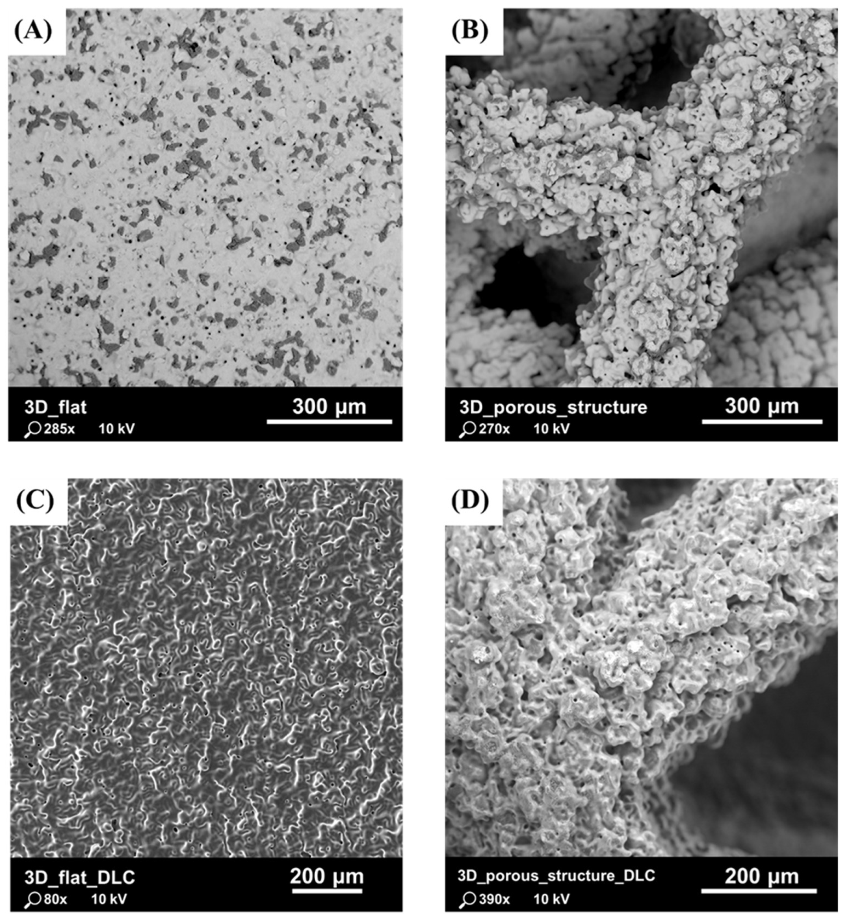
Previous studies, presented in Laskowska et al. [48], have shown that the parameters used in the binder jetting process allowed for the accurate reproduction of the complex geometry of the tested substrates. Particular attention was paid to the surface morphology, which was characterized by a high degree of roughness due to the formation of agglomerates of fully melted powder grains and the staircase effect (Figure 3). It is presumed that, due to the specifics of the powder melting and densification processes, the risk of the mechanical detachment of powder grains from the surface of the component and their penetration into the body is lower with BJ technology compared to with L-PBF technology.

Figure 3.
SEM images of tested substrates: (A) flat substrate with as-built surface without DLC coating; (B) substrate with porous structure without DLC coating; (C) flat substrate with as-built surface with DLC coating; and (D) substrate with porous structure with DLC coating.
The characterization of the produced coating, as presented in Laskowska et al. [48], which included optical microscopy, SEM microscopy, Raman spectroscopy, and HRTEM microscopy, demonstrated that the applied RF PACVD process parameters allowed for the deposition of a DLC coating on each substrate surface with varying thicknesses (ranging from 30 nm to 230 nm). The imaging results obtained from a cross-section of substrates with porous structures indicated the locally continuous nature of the DLC coating (Figure 4).
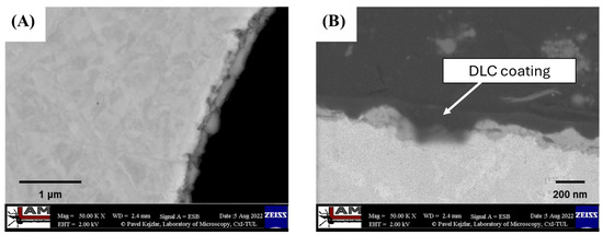
Figure 4.
SEM images of (A) cross-section of porous structure with DLC coating; and (B) DLC coating deposited on porous structure with thickness variation marked by blue arrows, based on Laskowska et al. [48].
To investigate the properties of the coating on a global scale, electrochemical corrosion and cytotoxicity tests were conducted. The cytotoxicity tests also allowed for the evaluation of the suitability of the proposed porous structure design as a scaffold for cell growth.
3.1. Electrochemical Corrosion
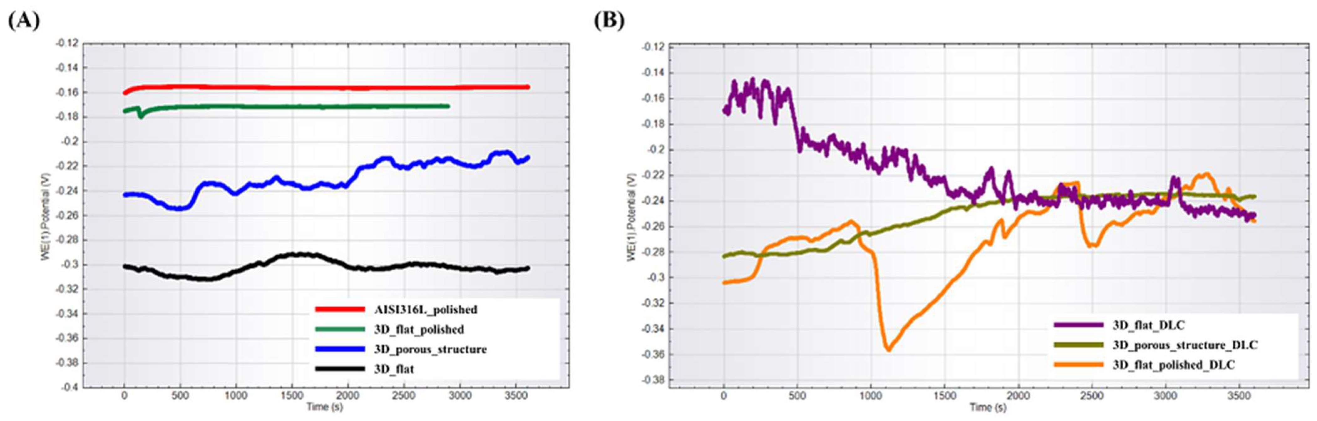
Open-circuit potential curves for the tested substrates are presented in Figure 5. Among the tested substrates without DLC coating, the lowest and the most similar to the reference samples OCP, and thus the highest corrosion resistance, was exhibited by the substrate with a polished surface (labeled as 3D_flat_polished). The flat sample with an unpolished surface (labelled as 3D_flat) and the sample with a porous structure (labelled as 3D_porous_structure) had OCP potentials shifted in the negative direction, indicating a greater tendency to corrosion. The substrates with the deposited DLC coating exhibited the longest stabilization time of the OCP potential, which indicated a high surface activity. Ultimately, all the samples established a similar OCP potential values in the range of −0.22 V to −0.26 V.
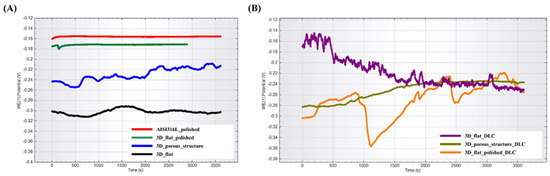
Figure 5.
OPC potential for tested substrates manufactured using binder jetting technology from stainless steel 316L powder (A) without DLC coating and (B) with DLC coating.
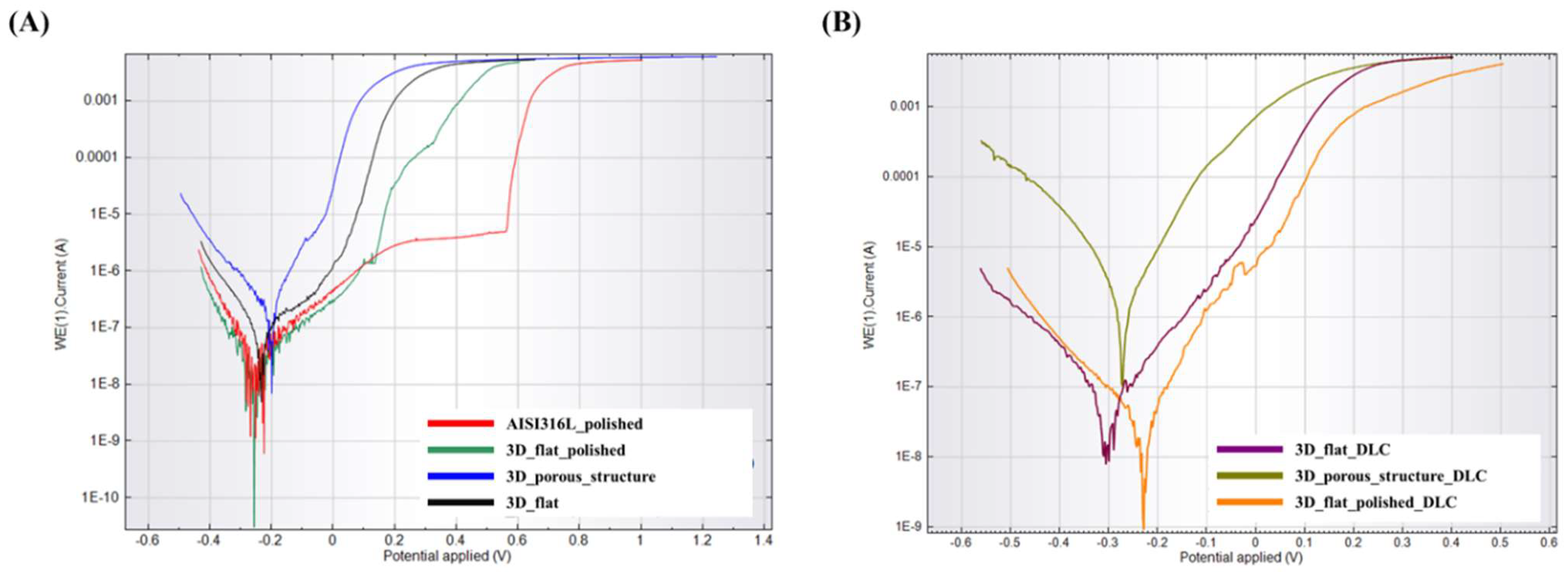
Potentiodynamic polarization curves for the tested substrates before surface modification with a DLC coating are shown in Figure 6A. The course of the potentiodynamic curve for a flat sample with a polished surface (labelled as 3D_flat_polished) is similar to the reference sample (labelled as AISI316L_polished). In both cases, a passivation area with a breakthrough point can be observed. For the 3D_flat_polished sample, the breakthrough point was shifted in relation to the reference sample and was 0.13 V. There is no clear passivation area or breakthrough point in the curves for the remaining substrates, labelled as 3D_flat and 3D_porous_structure. These samples also showed higher values of corrosion potential (Ecor) and corrosion current density (Icor), which indicated a high surface activity and tendency toward corrosion (Table 5).
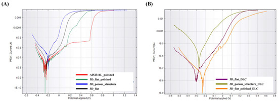
Figure 6.
Potentiodynamic polarization curves for the tested substrates manufactured using binder jetting technology from stainless steel 316L powder (A) without DLC coating and (B) with DLC coating.
Table 5.
The corrosion potential (Ecor), corrosion current density (Icor), and corrosion rate (CR) for the tested samples.
Figure 6B shows the potentiodynamic polarization curves for the tested substrates after modification with a DLC. Analyzing the course of the potentiodynamic curves and the data presented in Table 5, it was noted that in the presence of the DLC coating contributed to increased corrosion resistance only in the case of substrates with as-built surfaces (labelled as 3D_flat_DLC). For the sample with a porous structure, no improvement in corrosion resistance was observed. However, this model is difficult to analyze and compare with the flat surface due to the significant surface development and additional electrochemical phenomena that may occur in the surface irregularities. For the sample with a porous structure, the actual surface area is more challenging to estimate. The designed surface area of the sample with a porous structure was 10.85 cm2. All the samples were sintered in a single high-temperature sintering stage, allowing for the assumption that the scale of shrinkage was similar for all of the samples. This is a very rough assumption in the case of porous structures. However, it allows for the estimation that the actual surface area of the sample with a porous structure was 10.99 cm2. As is evident from the above explanations, estimating the actual surface area of the sample with a porous structure is subject to some inaccuracy. Consequently, the corrosion rate values would also be estimated with errors. It is worth noting that a complete and accurate value of the actual surface area of samples with a porous structure could be obtained by performing a computed tomography (CT) scan. Additionally, it should be considered that the applied coating varied in thickness. Areas covered with a thicker DLC coating may be characterized by a lower adhesion of the coating to the substrate and by dissolving faster in the solution used for testing.
3.2. Cytotoxicity Test
3.2.1. Cell Viability
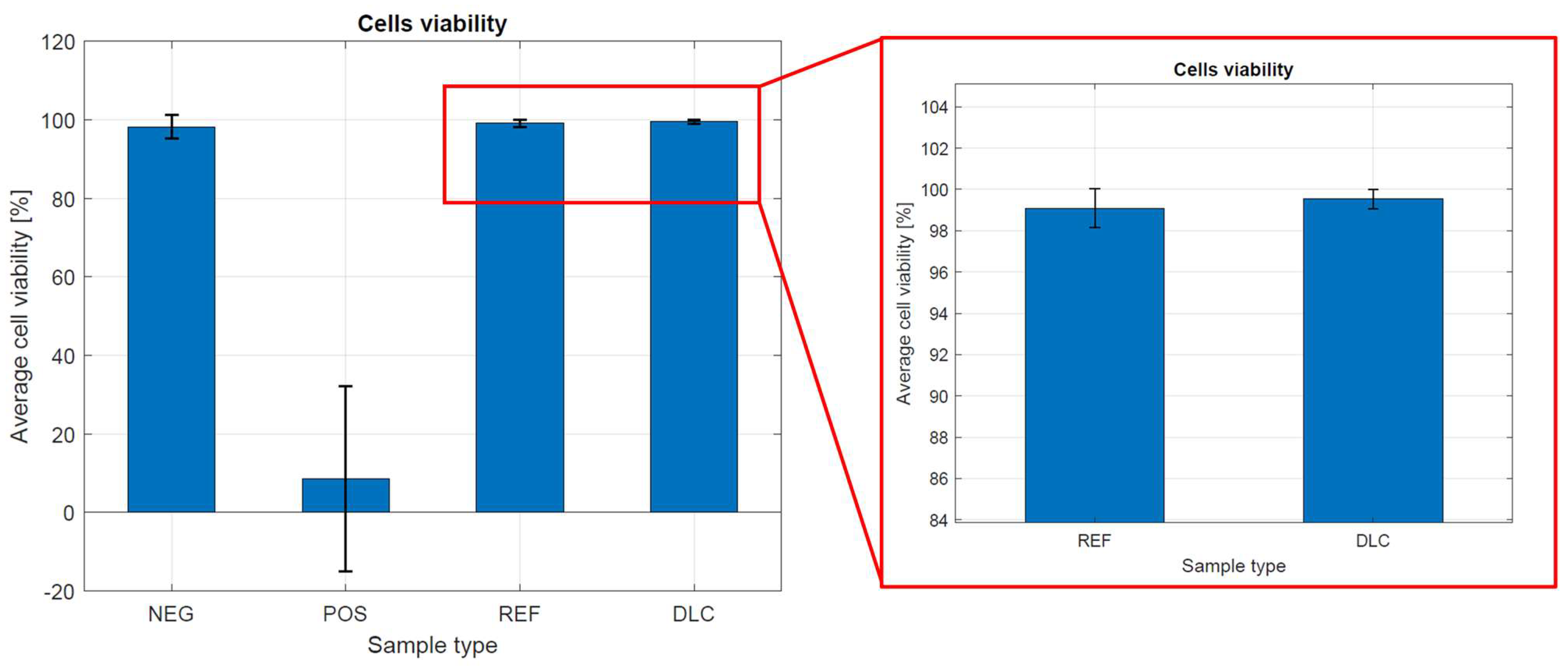
Figure 7 shows the cell viability in the presence of metal tested samples without and with DLC coatings. Cell viability was calculated from the following formula:
Viability = [number of live cells/(number of life cells + number of dead cells)] × 100%.
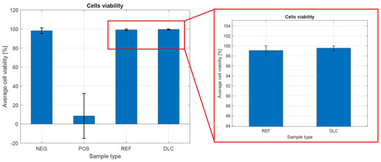
Figure 7.
Cell viability in the presence of metal tested samples without and with DLC coating.
Cell viability on the control and metal tested samples without and with DLC coatings was about 99.00%. In determining the cytotoxicity of metal tested samples without and with DLC coatings, it was clearly observed that the degree of cytotoxicity and reactivity of the tested materials were very low. The results show that the examined samples do not show a cytotoxic effect on the viability of the fibroblast line, clone L929. These results prove the biocompatibility of both materials and high-quality metallic samples without a DLC coating. The complicated shape of the sample and its porosity influence the received results, which cannot be compared with the results of flat samples.
3.2.2. Assessment of Metabolic Activity
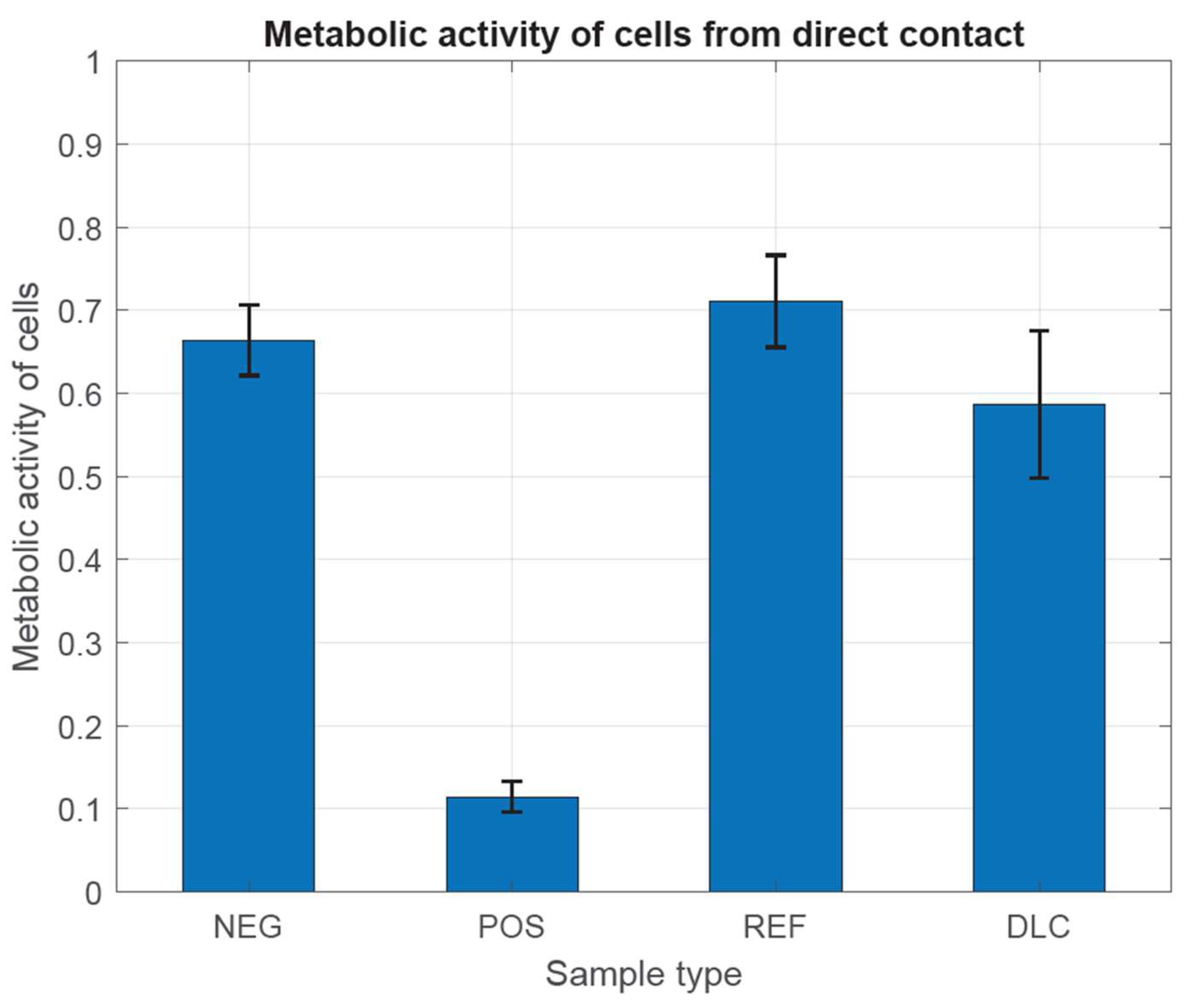
In Figure 8 and Figure 9, we have observed that the metabolic activity is expected to be directly proportional to the number of viable cells in the culture vessel. According to the guidelines of the ISO 10993-5 standard, the examined cells have characteristically high metabolic activity, which does not indicate the cytotoxic effect of the tested metal samples, both with and without DLC coating, in comparison with both controls. This is most likely due to the complex shape of the samples and the different thickness of the DLC coating, which did not allow for achieving differences. Different thicknesses of the DLC coating could even provoke a decrease in the metabolic activity of cells by changing the structure of the substrate and thus increasing the possibility of mechanical damage to the tested cells.
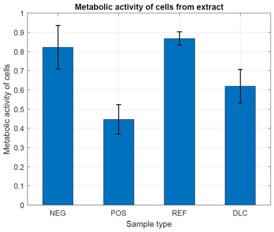
Figure 8.
Assessment of metabolic activity in the presence of metal tested samples without and with DLC coating.

Figure 9.
Assessment of metabolic activity in the presence of metal tested samples without and with DLC coating.
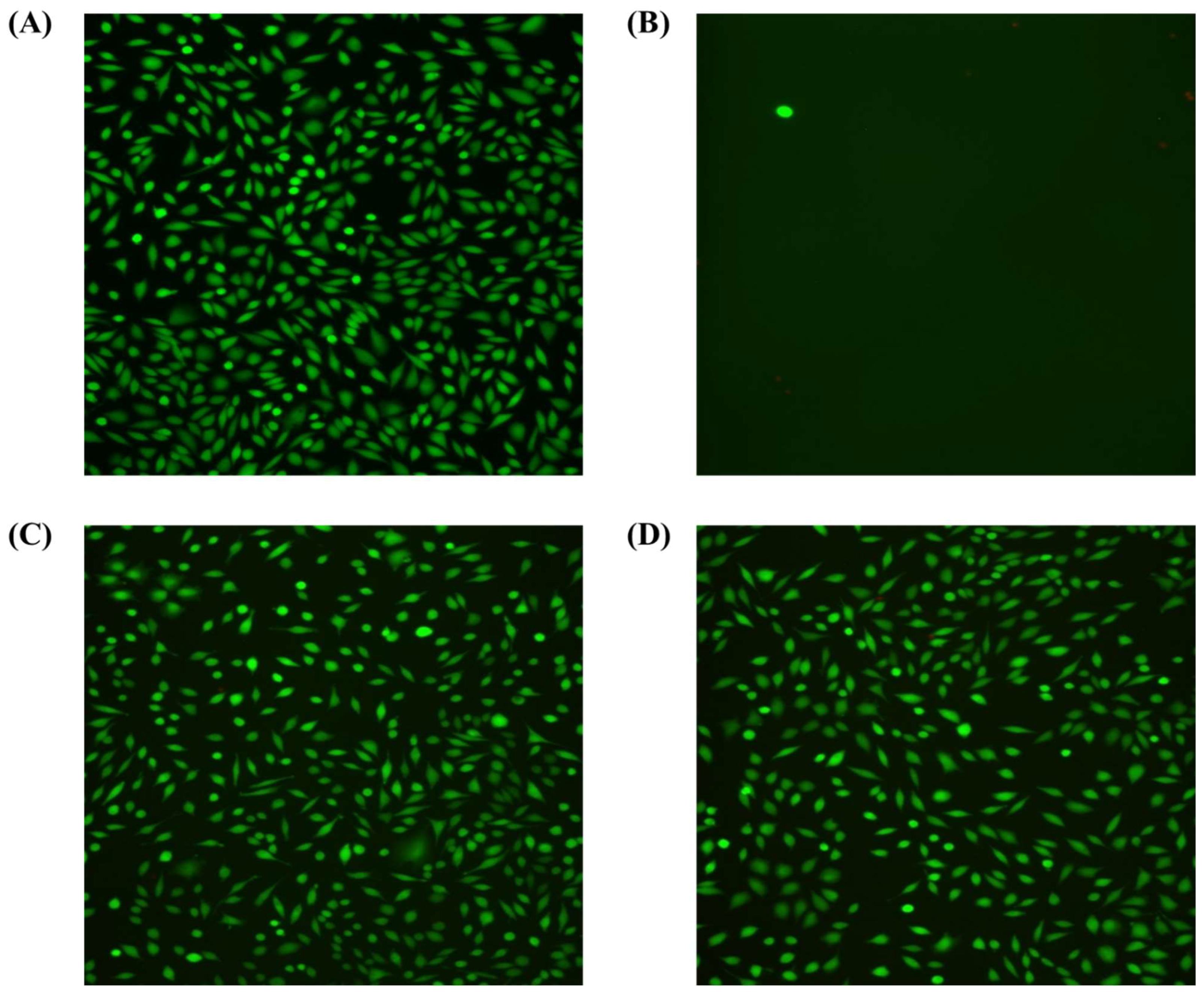
Figure 10 shows that in all tested samples, high cell viability was observed with only single necrotic cells in the field of view. The cells showed normal morphology. There were also no significant changes in cell density. The degree of cytotoxicity of the tested samples was classified as minor reactivity (grade 1) (Table 4). The fluorescence microscope results show that both samples have a similar cell density on the surface, but probes with DLC coating have been characterized by greater surface order.
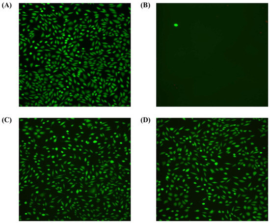
Figure 10.
The fluorescence microscope shows the fibroblast line, clone L929 (green fluorescence) in (A) the negative control—fresh culture medium without additives; (B) the positive control—fresh culture medium with sodium cyanide added at a concentration of 1.25 mg/mL; (C) the reference samples—extract from unmodified discs or unmodified discs; and (D) test samples—extract from DLC discs or DLC discs.
4. Conclusions
The aim of this study was to investigate the corrosion resistance and cytotoxicity of porous structures designed to enhance the osseointegration potential of implant surfaces. The structures were manufactured using BJ technology from 316L stainless steel powder, and their surfaces were modified with a DLC coating. Based on the research conducted, the following conclusions were formulated:
- Surface morphology and roughness had the greatest impact on the DLC coating deposition process.
- The DLC coating did not affect the macroporous structure of the elements and, at the same time, tightly covered their surface within the tested range.
- Flat samples with a polished and as-built surface showed higher corrosion resistance both before and after modification with a DLC coating in comparison to the samples with a porous structure. However, this model is difficult to analyze and compare with a flat surface due to the significant development of the tested surface and additional electrochemical phenomena that may occur in surface irregularities.
- The obtained electrochemical corrosion test results indicate the possibility of the discontinuity of the DLC coating, especially on substrates with a porous structure.
- In the presented results of the cytotoxicity studies, no statistical cytotoxic effect was demonstrated for mouse fibroblast cells in the presence of unmodified metal samples and those modified with DLC coatings. No significant differences were observed between DLC-coated samples and uncoated samples. However, the biocompatibility of the tested biomaterials was demonstrated, and the need to modify the parameters of sample design for printing and the parameters of DLC coating production to achieve a uniform coating thickness was highlighted.
The obtained research results show how important issues related to prior surface preparation are for further work on the surface modification of porous elements and structures manufactured using AM technologies. The surface modification of porous structures produced additively with a DLC coating deposited using plasma–chemical technologies is characterized by its good efficiency. The so-called diffusion barrier protects the living organism against the toxic process of metallosis. The low cytotoxicity of the cells was proven in studies carried out on porous metal samples with and without DLC coatings. However, no statistically significant differences were found between the uncoated metal samples and the samples coated with a DLC coating, which is most likely related to the different thicknesses of these carbon coatings on the tested porous samples and the occurrence of mechanical damage.
Therefore, further work should focus on modifying the parameters of coating deposition and substrate surface preparation in order to improve the corrosion properties and achieve a uniform coating thickness over the entire tested sample surface. This will be a very extensive research topic related to modifying the design of these samples for printing, and it will be necessary to modify the parameters for applying the DLC coating. This will allow for obtaining more precise test results, proving the high biocompatibility of the DLC coating as a diffusion barrier.
Author Contributions
Conceptualization, D.L. and K.M.; methodology, D.L., K.M., P.W., W.K. and J.G.; validation, D.L., K.M., P.W. and J.G.; formal analysis, A.S. and J.G.; investigation, D.L., A.S., J.G., L.S. and T.B.; resources, B.B.; data curation, D.L.; writing—original draft preparation, D.L.; writing—review and editing, K.M., B.B. and S.M.; visualization, D.L.; supervision, K.M., B.B. and S.M. All authors have read and agreed to the published version of the manuscript.
Funding
This research received no external funding.
Institutional Review Board Statement
Not applicable.
Informed Consent Statement
Not applicable.
Data Availability Statement
The data will be made available on request.
Conflicts of Interest
The authors declare no conflicts of interest.
References
- Yuan, L.; Ding, S.; Wen, C. Additive manufacturing technology for porous metal implant applications and triple minimal surface structures: A review. Bioact. Mater. 2019, 4, 56–70. [Google Scholar] [CrossRef] [PubMed]
- Kawar, S.; Vijayavenkataraman, S. Design of 3D printed scaffolds for bone tissue engineering: A review. Bioprinting 2021, 24, e00167. [Google Scholar] [CrossRef]
- Bandyopadhyay, A.; Mitra, I.; Avila, J.D.; Upadhyayula, M.; Bose, S. Porous metal implants: Processing, properties, and challenges. Int. J. Extreme Manuf. 2023, 5, 032014. [Google Scholar] [CrossRef]
- Rana, M.; Karmakar, S.K.; Pal, B.; Datta, P.; Roychowdhury, A.; Bandyopadhyay, A. Design and manufacturing of biomimetic porous metal implants. J. Mater. Res. 2021, 36, 3952–3962. [Google Scholar] [CrossRef]
- Wang, Z.; Zhang, M.; Liu, Z.; Wang, Y.; Dong, W.; Zhao, S.; Sun, D. Biomimetic design strategy of complex porous structure based on 3D printing Ti-6Al-4V scaffolds for enhanced osseointegration. Mater. Des. 2022, 218, 110721. [Google Scholar] [CrossRef]
- Woodard, J.R.; Hilldore, A.J.; Lan, S.K.; Park, C.J.; Morgan, A.W.; Eurell, J.A.C.; Clark, S.G.; Wheeler, M.B.; Jamison, R.D.; Wagoner, A.J. The mechanical properties and osteoconductivity of hydroxyapatite bone scaffolds with multi-scale porosity. Biomaterials 2007, 28, 45–54. [Google Scholar] [CrossRef] [PubMed]
- Murr, L.E. Strategies for creating living, additively manufactured, open-cellular metal and alloy implants by promoting osseointegration, osteoinduction and vascularization: An overview. J. Mater. Sci. Technol. 2019, 35, 231–241. [Google Scholar] [CrossRef]
- Liu, Y.; Rath, B.; Tingart, M.; Eschweiler, J. Role of implants surface modification in osseointegration: A systematic review. J. Biomed. Mater. Res. Part A 2020, 108, 470–484. [Google Scholar] [CrossRef]
- Jahani, B.; Wang, X. The Effects of Surface Roughness on the Functionality of Ti13Nb13Zr Orthopedic Implants. Biomed. J. Sci. Tech. Res. 2021, 38, 30058–30067. [Google Scholar] [CrossRef]
- Maconachie, T.; Leary, M.; Lozanovski, B.; Zhang, X.; Qian, M.; Faruque, O.; Brandt, M. SLM lattice structures: Properties, performance, applications and challenges. Mater. Des. 2019, 183, 108137. [Google Scholar] [CrossRef]
- Riva, L.; Ginestra, P.S.; Ceretti, E. Mechanical characterization and properties of laser-based powder bed–fused lattice structures: A review. Int. J. Adv. Manuf. Technol. 2021, 113, 649–671. [Google Scholar] [CrossRef]
- Amani, Y.; Dancette, S.; Delroisse, P.; Simar, A.; Maire, E. Compression behavior of lattice structures produced by selective laser melting: X-ray tomography based experimental and finite element approaches. Acta Mater. 2018, 159, 395–407. [Google Scholar] [CrossRef]
- Du Plessis, A.; Razavi, N.; Benedetti, M.; Murchio, S.; Leary, M.; Watson, M.; Bhate, D.; Berto, F. Properties and applications of additively manufactured metallic cellular materials: A review. Prog. Mater. Sci. 2022, 125, 100918. [Google Scholar] [CrossRef]
- Benedetti, M.; Du Plessis, A.; Ritchie, R.O.; Dallago, M.; Razavi, N.; Berto, F. Architected cellular materials: A review on their mechanical properties towards fatigue-tolerant design and fabrication. Mater. Sci. Eng. R Rep. 2021, 144, 100606. [Google Scholar] [CrossRef]
- Chen, H.; Liu, Y.; Wang, C.; Zhang, A.; Chen, B.; Han, Q.; Wang, J. Design and properties of biomimetic irregular scaffolds for bone tissue engineering. Comput. Biol. Med. 2021, 130, 104241. [Google Scholar] [CrossRef] [PubMed]
- Du, Y.; Liang, H.; Xie, D.; Mao, N.; Zhao, J.; Tian, Z.; Wang, C.; Shen, L. Design and statistical analysis of irregular porous scaffolds for orthopedic reconstruction based on voronoi tessellation and fabricated via selective laser melting (SLM). Mater. Chem. Phys. 2020, 239, 121968. [Google Scholar] [CrossRef]
- Deering, J.; Dowling, K.I.; DiCecco, L.A.; McLean, G.D.; Yu, B.; Grandfield, K. Selective Voronoi tessellation as a method to design anisotropic and biomimetic implants. J. Mech. Behav. Biomed. Mater. 2021, 116, 104361. [Google Scholar] [CrossRef]
- Liang, H.; Yang, Y.; Xie, D.; Li, L.; Mao, N.; Wang, C.; Tian, Z.; Jiang, Q.; Shen, L. Trabecular-like Ti-6Al-4V scaffolds for orthopedic: Fabrication by selective laser melting and in vitro biocompatibility. J. Mater. Sci. Technol. 2019, 35, 1284–1297. [Google Scholar] [CrossRef]
- Yang, L.; Mertens, R.; Ferrucci, M.; Yan, C.; Shi, Y.; Yang, S. Continuous graded Gyroid cellular structures fabricated by selective laser melting: Design, manufacturing and mechanical properties. Mater. Des. 2019, 162, 394–404. [Google Scholar] [CrossRef]
- Maskery, I.; Sturm, L.; Aremu, A.O.; Panesar, A.; Williams, C.B.; Tuck, C.J.; Wildman, R.D.; Ashcroft, I.A.; Hague, R.J.M. Insights into the mechanical properties of several triply periodic minimal surface lattice structures made by polymer additive manufacturing. Polymer 2018, 152, 62–71. [Google Scholar] [CrossRef]
- Dong, Z.; Zhao, X. Application of TPMS structure in bone regeneration. Eng. Regen. 2021, 2, 154–162. [Google Scholar] [CrossRef]
- Laskowska, D.; Szatkiewicz, T.; Bałasz, B.; Mitura, K. Mechanical Properties and Energy Absorption Abilities of Diamond TPMS Cylindrical Structures Fabricated by Selective Laser Melting with 316L Stainless Steel. Materials 2023, 16, 3196. [Google Scholar] [CrossRef] [PubMed]
- Williams, D.F. On the mechanisms of biocompatibility. Biomaterials 2008, 29, 2941–2953. [Google Scholar] [CrossRef] [PubMed]
- Sahoo, P.; Das, S.K.; Paulo Davim, J. Tribology of materials for biomedical applications. In Mechanical Behaviour of Biomaterials; Paulo Davim, J., Ed.; Elsevier: Amsterdam, The Netherlands, 2019; pp. 1–45. [Google Scholar] [CrossRef]
- Ali, S.; Abdul Rani, A.R.; Baig, Z.; Ahmed, S.W.; Hussain, G.; Subramaniam, K.; Hastuty, S.; Rao, T.V.V.L.N. Biocompatibility and corrosion resistance of metallic biomaterials. Corros. Rev. 2020, 38, 381–402. [Google Scholar] [CrossRef]
- Zitter, H.; Plenk, H. The electrochemical behavior of metallic implant materials as an indicator of their biocompatibility. J. Biomed. Mater. Res. 1987, 21, 881–896. [Google Scholar] [CrossRef] [PubMed]
- Ude, C.C.; Esdaille, C.J.; Ogueri, K.S.; Kan, H.-M.; Laurencin, S.J.; Nair, L.S.; Laurencin, C.T. The Mechanism of Metallosis After Total Hip Arthroplasty. Regen. Eng. Transl. Med. 2021, 7, 247–261. [Google Scholar] [CrossRef] [PubMed]
- Mushtaq, M.; Qureshi, O.A.; Dua, A.; Khan, S.; Mehraj, M. Metallosis and Nonunion: A Case Series and Literature Review. Cureus 2023, 15, e35385. [Google Scholar] [CrossRef] [PubMed]
- Cañizares, S.; Carrera Barriga, G.C.; Valencia Jarrín, F.; Poveda Freire, C.D. Metallosis After Oxinium Total Knee Arthroplasty in a Patient With Rheumatoid Arthritis: A Case Report. Cureus 2023, 15, e34541. [Google Scholar] [CrossRef] [PubMed]
- Arima, M.; Matsuzawa, T.; Hashimoto, E.; Ochiai, N.; Matsusaka, K.; Inozume, T. A case of metallosis mimicking cutaneous malignant melanoma following total elbow arthroplasty. JEADV Clin. Pract. 2023, 2, 343–346. [Google Scholar] [CrossRef]
- Asri, R.I.M.; Harun, W.S.W.; Samykano, M.; Lah, N.A.C.; Ghani, S.A.C.; Tarlochan, F.; Raza, M.R. Corrosion and surface modification on biocompatible metals: A review. Mater. Sci. Eng. C 2017, 77, 1261–1274. [Google Scholar] [CrossRef]
- Bandyopadhyay, A.; Mitra, I.; Goodman, S.B.; Kumar, M.; Bose, S. Improving biocompatibility for next generation of metallic implants. Prog. Mater. Sci. 2023, 133, 101053. [Google Scholar] [CrossRef] [PubMed]
- Roy, R.K.; Lee, K.R. Biomedical applications of diamond-like carbon coatings: A review. J. Biomed. Mater. Res. Part B 2007, 83, 72–84. [Google Scholar] [CrossRef]
- Korepanov, V.I.; Hamaguchi, H.; Osawa, E.; Ermolenkov, V.; Lednev, I.K.; Etzold, B.J.M.; Levinson, O.; Zousman, B.; Epperla, C.P.; Chang, H.-C. Carbon structure in nanodiamonds elucidated from Raman spectroscopy. Carbon 2017, 121, 322–329. [Google Scholar] [CrossRef]
- Chauhan, S.; Jain, N.; Nagaich, U. Nanodiamonds with powerful ability for drug delivery and biomedical applications: Recent updates on in vivo study and patents. J. Pharm. Anal. 2020, 10, 1–12. [Google Scholar] [CrossRef]
- Zakrzewska, K.E.; Samluk, A.; Wierzbicki, M.; Jaworski, S.; Kutwin, M.; Sawosz, E.; Chwalibog, A.; Pijanowska, D.G.; Pluta, K.D. Analysis of the Cytotoxicity of Carbon-Based Nanoparticles, Diamond and Graphite, in Human Glioblastoma and Hepatoma Cell Lines. PLoS ONE 2015, 10, e0122579. [Google Scholar] [CrossRef] [PubMed]
- Peng, Y.; Peng, J.; Wang, Z.; Xiao, Y.; Qiu, X. Diamond-like Carbon Coatings in the Biomedical Field: Properties, Applications and Future Development. Coatings 2022, 12, 1088. [Google Scholar] [CrossRef]
- Ferrari, A.C.; Robertson, J. Interpretation of Raman spectra of disordered and amorphous carbon. Phys. Rev. B 2000, 61, 14095–14107. [Google Scholar] [CrossRef]
- Whitlow, J.; Pacelli, S.; Paul, A. Multifunctional nanodiamonds in regenerative medicine: Recent advances and future directions. J. Control. Release 2017, 61, 593–602. [Google Scholar] [CrossRef] [PubMed]
- Solarska-Ściuk, K.; Gajewska, A.; Skolimowski, J.; Gajek, A.; Bartosz, G. Cellular redox homeostasis in endothelial cells treated with nonmodified and Fenton-modified nanodiamond powders. Biotechnol. Appl. Biochem. 2014, 61, 593–602. [Google Scholar] [CrossRef]
- Schrand, A.M.; Huang, H.; Carlson, C.; Schlager, J.J.; Ōsawa, E.; Hussain, S.M.; Dai, L. Are Diamond Nanoparticles Cytotoxic? J. Phys. Chem. 2007, 111, 2–7. [Google Scholar] [CrossRef]
- Bociaga, D.; Mitura, K. Biomedical effect of tissue contact with metallic material used for body piercing modified by DLC coatings. Diam. Relat. Mater. 2008, 17, 1410–1415. [Google Scholar] [CrossRef]
- Niemiec, T.; Szmidt, M.; Sawosz, E.; Grodzik, M.; Mitura, K. The Effect of Diamond Nanoparticles on Redox and Immune Parameters in Rats. J. Nanosci. Nanotechnol. 2011, 11, 9072–9077. [Google Scholar] [CrossRef] [PubMed]
- Myrzagali, S.; Omarova, Z.; Zeitkaziyeva, D.; Madet, A.; Xie, Y. Carbon nanoparticle-induced cell death. Carbon Trends 2024, 15, 100352. [Google Scholar] [CrossRef]
- Liu, Y.; Huang, C.; Yue, W.; Wang, X.; Sun, Y.; Bi, W.; Wang, L.; Xu, Y. Sugar-coated cannonballs for effective antibacterial treatments but with negligible cytotoxicity based on silver (copper) -containing carbon dots and their mechanism analysis. Carbon 2024, 224, 119085. [Google Scholar] [CrossRef]
- Shaimoldina, A.; Sergazina, A.; Myrzagali, S.; Nazarbek, G.; Omarova, Z.; Mirza, O.; Fan, H.; Amin, A.; Zhou, W.; Xie, Y. Carbon nanoparticles neutralize carbon dioxide (CO2) in cytotoxicity: Potent carbon emission induced resistance to anticancer nanomedicine and antibiotics. Ecotoxicol. Environ. Saf. 2024, 273, 116024. [Google Scholar] [CrossRef] [PubMed]
- nTopology. 2020. Available online: https://ntopology.com/ (accessed on 2 May 2024).
- Laskowska, D.; Bałasz, B.; Kaczorowski, W.; Grabarczyk, J.; Svobodova, L.; Szatkiewicz, T.; Mitura, K. The DLC Coating on 316L Stainless Steel Stochastic Voronoi Tessellation Structures Obtained by Binder Jetting Additive Manufacturing for Potential Biomedical Applications. Coatings 2022, 12, 1373. [Google Scholar] [CrossRef]
- Bose, S.; Ke, D.; Sahasrabudhe, H.; Bandyopadhyay, A. Additive manufacturing of biomaterials. Prog. Mater. Sci. 2018, 93, 45–111. [Google Scholar] [CrossRef] [PubMed]
- Mostafaei, A.; Elliott, A.M.; Barnes, J.E.; Li, F.; Tan, W.; Cramer, C.L.; Nandwana, P.; Chmielus, M. Binder jet 3D printing—Process parameters, materials, properties, modeling, and challenges. Prog. Mater. Sci. 2021, 119, 100707. [Google Scholar] [CrossRef]
- Grabarczyk, J.; Batory, D.; Kaczorowski, W.; Pązik, B.; Januszewicz, B.; Burnat, B.; Czerniak-Reczulska, M.; Makówka, M.; Niedzielski, P. Comparison of Different Thermo-Chemical Treatments Methods of Ti-6Al-4V Alloy in Terms of Tribological and Corrosion Properties. Materials 2020, 13, 5192. [Google Scholar] [CrossRef]
- ISO 10993-12:2021; Biological Evaluation of Medical Devices, Part 12: Sample Preparation and Reference Materials, Edition 5. ISO: Geneva, Switzerland, 2021.
- ISO 10093-5:2009; Biological Evaluation of Medical Devices, Part 5: Tests for In Vitro Cytotoxicity, Edition 3. ISO: Geneva, Switzerland, 2009.
- Mitura, K.; Kornacka, J.; Niemiec-Cyganek, A.; Pawlus-Łacgecka, L.; Mydłowska, K.; Sobczyk-Guzenda, A.; Kaczorowski, W.; Ossowska, P.; Bałasz, B.; Wilczek, P. The Influence of Diamond Nanoparticles on Fibroblast Cell Line L929, Cytotoxicity and Bacteriostaticity of Selected Pathogens. Coatings 2022, 12, 280. [Google Scholar] [CrossRef]


Disclaimer/Publisher’s Note: The statements, opinions and data contained in all publications are solely those of the individual author(s) and contributor(s) and not of MDPI and/or the editor(s). MDPI and/or the editor(s) disclaim responsibility for any injury to people or property resulting from any ideas, methods, instructions or products referred to in the content. |
© 2024 by the authors. Licensee MDPI, Basel, Switzerland. This article is an open access article distributed under the terms and conditions of the Creative Commons Attribution (CC BY) license (https://creativecommons.org/licenses/by/4.0/).