Article

Ni-MoO2 Composite Coatings Electrodeposited at Porous Ni Substrate as Efficient Alkaline Water Splitting Cathodes

by
Aleksandar Petričević
1,
Jelena Gojgić
1,
Christian I. Bernäcker
2,
Thomas Rauscher
2,
Marjan Bele
3,
Milutin Smiljanić
3,
Nejc Hodnik
3,
Nevenka Elezović
1,
Vladimir D. Jović
1 and
Mila N. Krstajić Pajić
4,*
1
Institute for Multidisciplinary Research, University of Belgrade, Kneza Višeslava 1, 11030 Belgrade, Serbia
2
Fraunhofer Institute for Manufacturing Technology and Advanced Materials IFAM, Winterbergstraße 28, 01277 Dresden, Germany
3
National Institute of Chemistry, Hajdrihova 19, 1000 Ljubljana, Slovenia
4
Faculty of Technology and Metallurgy, University of Belgrade, Karnegijeva 4, 11000 Belgrade, Serbia
*
Author to whom correspondence should be addressed.
Coatings 2024, 14(8), 1026; https://doi.org/10.3390/coatings14081026
Submission received: 1 July 2024 / Revised: 3 August 2024 / Accepted: 8 August 2024 / Published: 13 August 2024

Abstract

:
To obtain highly efficient yet easily produced water-splitting cathodes, Ni-MoO2 composite coatings were electrodeposited at a Ni foam substrate with an open-pore structure, pore size of 450 µm, in a Watts-type bath. The concentration of MoO2 particles (about 100 nm) was varied, while the intensive mixing of the solution was provided by air bubbling with 0.5 L min−1. Electrodeposition was performed at different constant current densities at room temperature. The morphology and composition of the coatings were investigated by SEM and EDS. The hydrogen evolution reaction (HER) was tested in KOH of different concentrations, at several temperatures, in a three-electrode H-cell by recording polarization curves and EIS measurements. The lowest achieved HER overpotential was −158 mV at −0.5 A cm−2. Up-scaled samples, 3 × 3.3 cm2, were tested in a single zero-gap cell showing decreasing cell voltage (from 2.18 V to 2.11 V) at 0.5 A cm−2 over 5 h in 30% KOH at 70 °C with electrolyte flow rate of 58 mL min−1. Compared to pure Ni foams used as both cathode and anode under the same conditions, the cell voltage is decreased by 200 mV, showing improved electrode performance.

1. Introduction

Alkaline water electrolysis (AWE) is a mature technology for hydrogen production, with significant benefits such as the use of non-noble metal catalysts and the possibility of applying electric energy from periodical renewable power sources. Thus, it represents the most promising technology for green hydrogen production on a large scale. The need for green hydrogen is ever-growing since it represents an invaluable energy carrier, and it is also used for demanded green reactions such as carbon dioxide reduction [1,2], reduction of nitrates [3], and nitrogen fixation [4]. The high demand for green hydrogen encourages innovations in the AWE technology, changing the electrolyzer types over the years. Recently, zero-gap flow electrolyzers have emerged at the top of State-of-the-Art technologies, given the reduced ohmic losses in this cell type and the efficient gas removal from the electrode surface [5]. To ensure efficient electrolyte flow and dispersion of the formed gasses, three-dimensional electrodes with complex structures are the best choice for these systems.
Most hydrogen evolution reaction (HER) catalysts in alkaline environments are Nickel-based. Even though the industrial standard uses pure Nickel or Raney Nickel electrodes, these materials are struggling to meet the requirements for higher energy efficiency and the goals set by the US Department of Energy and the European Commission [6,7,8]. Luckily, the catalytic performance can be significantly improved by alloying Ni with other transition metals such as Mo [9,10,11,12], their oxides [13,14], sulfides [15,16,17,18], phosphides [19,20], etc. A recent review gives an overview of these materials, primarily for seawater electrolysis, but most of the materials are also used in alkaline water splitting [21]. To obtain a good quality electrode for industrial use, it has to demonstrate exceptional HER activity with fast kinetics, good long-term stability, and the ability to operate at high current densities (−1 A cm−2) for large-scale applications [12]. As mentioned above, zero-gap flow cells demand three-dimensional materials rather than commonly used Ni or Raney-Ni plates. The material of choice for these systems is metal foams that can be produced by different procedures [22]. Nickel foams with open-pore structures are made in a variety of pore sizes and provide good catalytic activity towards water-splitting reactions in alkaline media, as well as efficient electrolyte flow and gas removal from active sites [5]. The most efficient way to improve the catalytic performance of such electrodes is to coat them with a more active nickel-based alloy or composite. Among the many coating technologies, electrodeposition stands out as a way to easily control the coating thickness, morphology, and composition by applying optimal electrodeposition parameters. Additionally, this method can provide complete coverage of complex surfaces, such as open-pore structures, covering the inner and outer available sites with electroactive material. This enables the HER to take place on all available sites, even inside the foam structure. A detailed overview of the literature for catalyzed Ni foams as cathodes for water electrolysis has also been provided in our previous publication [23].
The choice of the catalyst among a wide range of nickel-based alloys and composites led to the use of MoO2 nanoparticles, which show excellent conductivity thanks to the distorted rutile structure and apparent metallic behavior of Mo2+ in oxides [13]. Namely, the role of molybdenum oxide species could be facilitating the hydrogen evolution kinetics through the spillover effect due to diffusion of the reaction intermediates–preferential adsorption of H a d s species, formed by Volmer reaction:
H 2 O + e H a d s + O H
Molybdenum oxide particles could act as an acceptor of the adsorbed hydrogen atoms, leading to the more available nickel active sites for further adsorption of hydrogen to proceed, which would accelerate the whole hydrogen evolution kinetics on nickel-based coatings with oxide particles inclusion. On the other hand, molybdenum oxide particles are conductive and could be electrochemically co-deposited parallel to nickel electrodeposition. Thus, the influence of molybdenum oxide species could be expected to be an effective way to increase the hydrogen evolution reaction rate through one of the two mechanisms mentioned above [13,14].
Also, it is shown in the literature that alloying Ni with Mo can enhance its catalytic activity significantly, especially in the catalysts prepared by electrodeposition [24,25,26,27]. When referring to composite coatings, they are produced by embedding Mo-containing particles during Ni electrodeposition from the same bath. One-step synthesis makes electrodeposition a simple procedure, compared to vacuum plasma spraying or hydrothermal routes that require several procedure steps with material pretreatment and additional surface finishing steps. The only requirement for electrodeposition is the removal of surface oxides/hydroxides from the foam substrate by simple etching and rinsing step [23].
In our previous investigations [14,28,29], we have studied the electrodeposition of Ni-MoO2 coatings at Ni mesh 40 from the solution containing 0.2 M NiCl2 + 2.0 M NH4Cl, while MoO2 powder was synthesized by the rheological procedure [8] and added in the electrolyte up to 3 g L−1. Obtained electrodes showed lower or equivalent HER overpotential compared to the commercial De Nora Ni-RuO2 cathode and slightly better performance during the accelerated service life test [28].
Based on these results, in this research, an attempt was made to perform electrodeposition of Ni-MoO2 coatings on Ni foam with the average pore size of 450 µm, a substrate that would suit better the use in zero-gap flow electrolyzer. Considering the porous structure of Ni foam, the first idea was to use ultrasound-assisted electrodeposition (often used in the literature [30,31,32,33,34,35,36]) of Ni and commercially available MoO2 particles of the smallest available size (100 nm MoO2) to obtain composite Ni-MoO2 coatings uniformly distributed at the surface and inside the porous structure of Ni foam. Several parameters were changed (solution composition, MoO2 concentration, power of ultrasound probe, etc.), but in all cases, quite a small amount of MoO2 particles was co-deposited with Ni, producing slightly more active electrodes than pure Ni foam. In the meantime, the ultrasonic probe also underwent noticeable damage from erosion caused by MoO2 nanoparticles present in the bath, possibly contributed by the present electric field. Although such behavior was not expected, we believe that the main reasons for these results are:
  • the size of MoO2 particles (they were bigger than non-metallic particles usually used in the processes of ultrasound-assisted electrodeposition of metals and non-metallic particles [30,31,32,33,34,35,36]);
  • the metallic type of conductivity that MoO2 exhibits (10−2 S cm−1 at room temperature according to literature data [37]); therefore, it cannot be considered a non-metallic particle;
  • in our previous investigations, MoO2 powders were obtained by the rheological process [8], most probably containing not only MoO2 particles but also an unknown amount of other non-stoichiometric Mo oxides, while in this case pure MoO2 powder (commercially available) was used.
Since ultrasound-assisted electrodeposition of Ni-MoO2 composite coatings was not successful, in this research, we have finally used a Watts-type bath containing different amounts of MoO2 particles of the average size of 100 nm for electrodeposition and provided intensive mixing of the solution by air bubbling (see Section 2.1). Under such conditions, much more active coatings for the HER were obtained, and the results are presented in Section 3. Such prepared electrodes have been tested in laboratories and industrial conditions and have demonstrated a great potential for high-scale hydrogen production in an alkaline environment.

2. Materials and Methods

Ni foams with an average pore size of 450 µm (designated as Ni foam 450) were obtained from Alantum (Munich, Germany) and were used in this research as electrodeposition substrates for Ni-MoO2 coatings. Preparation steps that precede electrodeposition were explained in detail in our previous publication [23]. The samples (approximately 1 × 1 cm2, assuming approximately 1 cm2 surface area, see Section 2.4) were made in a “hockey stick” shape to provide easy liberation of hydrogen bubbles from the pores of the Ni foam, both during electrodeposition and HER investigations in laboratory conditions (stationary electrolyte). For the experiments in a flow cell electrolyzer, the electrodes were cut into 3 × 3.3 cm2 rectangle samples (a geometric surface area of about 10 cm2).

2.1. Electrodeposition of Ni-MoO2 Composite Coatings on Ni Foam

Ni-MoO2 composite coatings were electrodeposited at Ni foam 450 from the Watts type bath (330 g L−1 NiSO4∙7H2O (Alfa Aesar 98%) + 45 g L−1 NiCl2∙6H2O (Alfa Aesar 99.3%) + 38 g L−1 H3BO3 (Carlo Erba 99.5%), pH 3.2–3.8) containing 1.0, 1.5, 2.0 and 2.5 g L−1 of MoO2 particles of the average size of 100 nm (MoO2 Nanopowder, Super Grade 99.99%, Purple Blue, Nanomaterials Inc., Houston, TX USA). Ni foam substrate was placed between two larger Ni meshes as counter electrodes. Intensive mixing of the solution was provided by bubbling air with 0.5 L min−1 through the spiral-type glass pipe with the perforation facing the bottom of the beaker to prevent MoO2 precipitation. Electrodeposition was conducted galvanostatically, most appropriate for industrial upscaling, at three different current densities: −50, −100, and −150 mA cm−2 at 25 °C for 30 min.

2.2. Physico-Chemical Characterization

Morphology, structure, and composition of the obtained Ni-MoO2 coatings were analyzed by Scanning Electron Microscopy performed on Carl Zeiss SUPRA 35 VP (Carl Zeiss Microscopy GmbH, Jena, Germany) equipped with energy-dispersive X-ray spectroscopy–Oxford SDD Ultim max 100 (Oxford Instruments, High Wycombe, UK). Metallographic cross-sections of the Ni-MoO2 coatings, prepared by a grinding and polishing procedure, were investigated by Light Microscopy Axio Observer (Carl Zeiss Microscopy GmbH, Jena, Germany) as well as by EDS.

2.3. HER Investigation

The HER was investigated in an H-cell with working and counter electrode compartments separated by the ZirfonTM PERL UTP 500 diaphragm. Pt mesh was used as a counter electrode, and Reversible hydrogen electrode (RHE)–HydroFlex (Gaskatel GmbH, Kassel, Germany) served as the reference, connected with the cell through a Luggin capillary. Potentiostat/Galvanostat ZRA Interface 1010E (Gamry Instruments Inc., Warminster, PA, USA) was used for the electrochemical experiments.
Prior to polarization curve measurements, Ni-MoO2/Ni foam 450 samples were held at j = −500 mA cm−2 for 10 min to remove any residues from the electrodeposition bath from the sample and prevent the surface oxidation upon emerging into the electrolyte. Polarization curves were recorded by linear sweep voltammetry (LSV) from η = −10 mV to maximum η = −300 mV and back (v = 1 mV s−1) by using the current interrupt technique for jR drop correction. The first polarization curve measurements were performed in 1.0 M KOH (Fisher Chemical ≥ 85%) at 25 °C in order to determine the electrode activity for the HER, while the best-performing sample was additionally tested in 30% KOH at 70 °C (industrial electrolysis conditions).
Furthermore, electrochemical impedance spectroscopy (EIS) measurements were conducted on the best-performing sample in 30% KOH at 70 °C at four different overpotentials (−50, −70, −90, −110 mV) in the frequency range from 20 kHz to 0.01 Hz, with the RMS amplitude of 5 mV and 20 points per decade. This was conducted before each EIS measurement electrode was kept at the same overpotential for 100 s to reach a stable current response.

2.4. Zero-Gap Single Cell Measurements

Single-cell experiments were performed in a laboratory zero-gap flow electrolyzer (Micro Flow Cell from ElectroCell A/S, Tarm, Denmark). The connection of the Ni-MoO2/Ni foam 450 with the Ni end plate of the cell was realized with bare Ni foam (current collector), while at the anode side, pure Ni foams served both as anode and a current collector (with Ni end plate). A ZirfonTM PERL UTP 500 diaphragm was used to separate the cathode and anode compartments.
The single-cell tests were performed using a slightly modified procedure suggested by the European Commission (EU harmonized polarization curve test method for low-temperature water electrolysis) [38]. A polarization curve, starting from the low current density up to 0.5 A cm−2, was first recorded. In the second step, a constant current density of 0.5 A cm−2 was applied for 5 h, while during the third step, the polarization curve was recorded using the same procedure as at the beginning. Additionally, an EIS measurement close to the reversible cell voltage is performed to evaluate the cell resistance under conditions where no gas bubbles are being evolved, RI (high-frequency resistance).

3. Results and Discussion

3.1. Physico-Chemical Characterization

The results of SEM-EDS analysis of Ni-MoO2/Ni foam 450 samples are presented in Figure 1, with coatings electrodeposited at different current densities under different magnifications: Figure 1a jdep = −50 mA cm−2; Figure 1b,c jdep = −100 mA cm−2. A common characteristic of all samples is the presence of large cracks, particularly on the thick part of the coatings on the outer surface of Ni foam. Such cracks cannot be detected deeper in the foam structure, and the thickness of the coatings inside the pores is much lower. Similar percentages of Mo were obtained for all spectra, while the percentages for Ni and O were found to vary depending on the position of analysis. Compositions of samples at analysis points are given in Table 1.
Microphotographs of the Ni-MoO2/Ni foam 450 surface are shown in Figure 2. As can be seen, the thickest coating (rich in Ni, white coating) is placed on top of the Ni foam surface, while the thinner coating (rich in Mo, grey coating) is placed deeper in the foam. According to Figure 1, EDS analysis was mainly performed on top of Ni foam in the region richer with Ni (Inset—lower magnification).

Cross-Section Light Microscopy (LM)

LM results of a cross-section of Ni-MoO2/Ni foam sample electrodeposited at j = −50 mA cm−2 (sample 1) are shown in Figure 3. It is obvious that most of the coating is placed on the surface of Ni foam and that at some places, the thickness of the coating reaches approximately 30–50 µm. Nevertheless, slim coatings (1–2 µm), marked with the arrows, can be detected at the Ni struts placed in the middle of the foam (A).
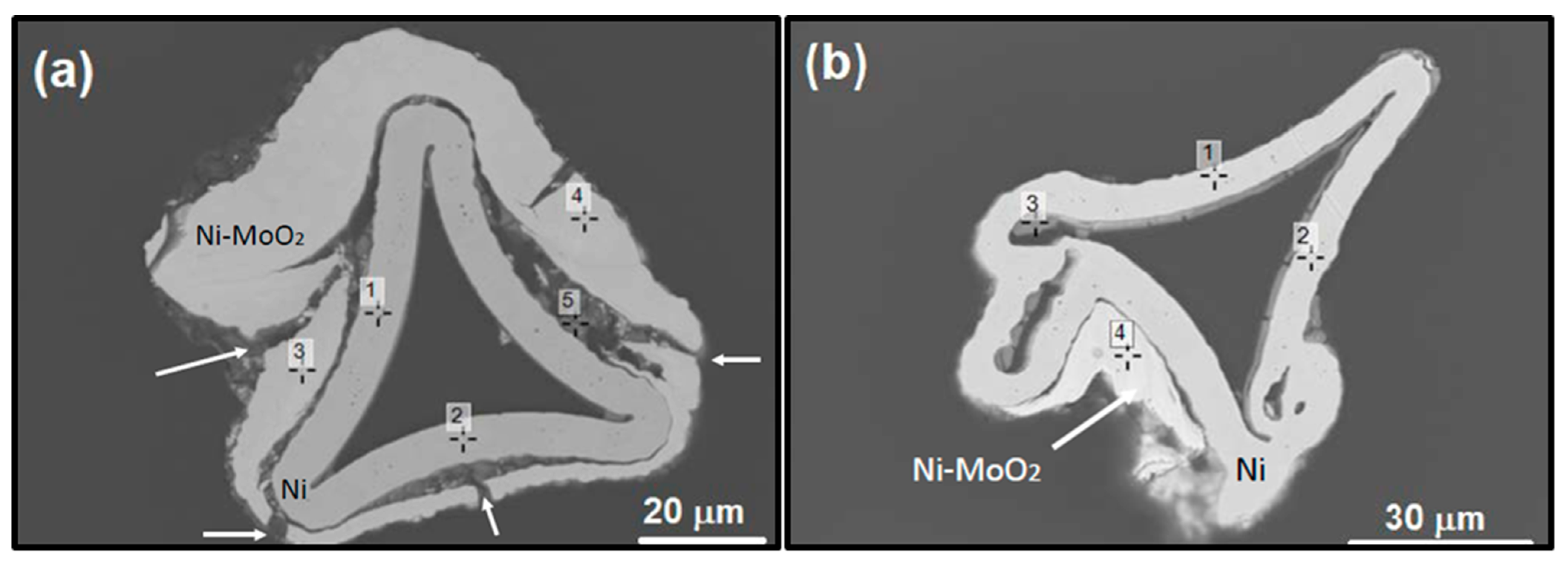
Similar results were obtained for the Ni-MoO2/Ni foam sample electrodeposited at j = −100 mA cm−2 (sample 2). SEM-EDS analysis of thick coatings for sample 2 is presented in Figure 4. The composition of Ni-MoO2 coating is given in Table 2, while the cracks in the coating are marked with arrows.

3.2. HER Polarization Curves in 1.0 M KOH at 25 °C

In order to determine the best-performing sample for the HER, polarization curves of all samples were first recorded in 1.0 M KOH at 25 °C and are presented in Figure 5. It can be seen in Figure 5a that the HER overpotential at −500 mA cm−2 decreases with increasing the concentration of MoO2, reaching a minimum of −187 mV for 2.5 g L−1 MoO2. After determining the optimal MoO2 concentration, the same solution was used to vary the deposition current density. Polarization curves recorded for samples deposited at −50, −100, and −150 mA cm−2 (Figure 5b) showed the best jη characteristics when the current density of −100 mA cm−2 was applied, especially regarding the high current range, with an overpotential of about −150 mV at –500 mA cm−2 (Figure 5b). This electrode was then subjected to HER testing in industrial conditions.

3.3. HER Investigation in 30% KOH at 70 °C

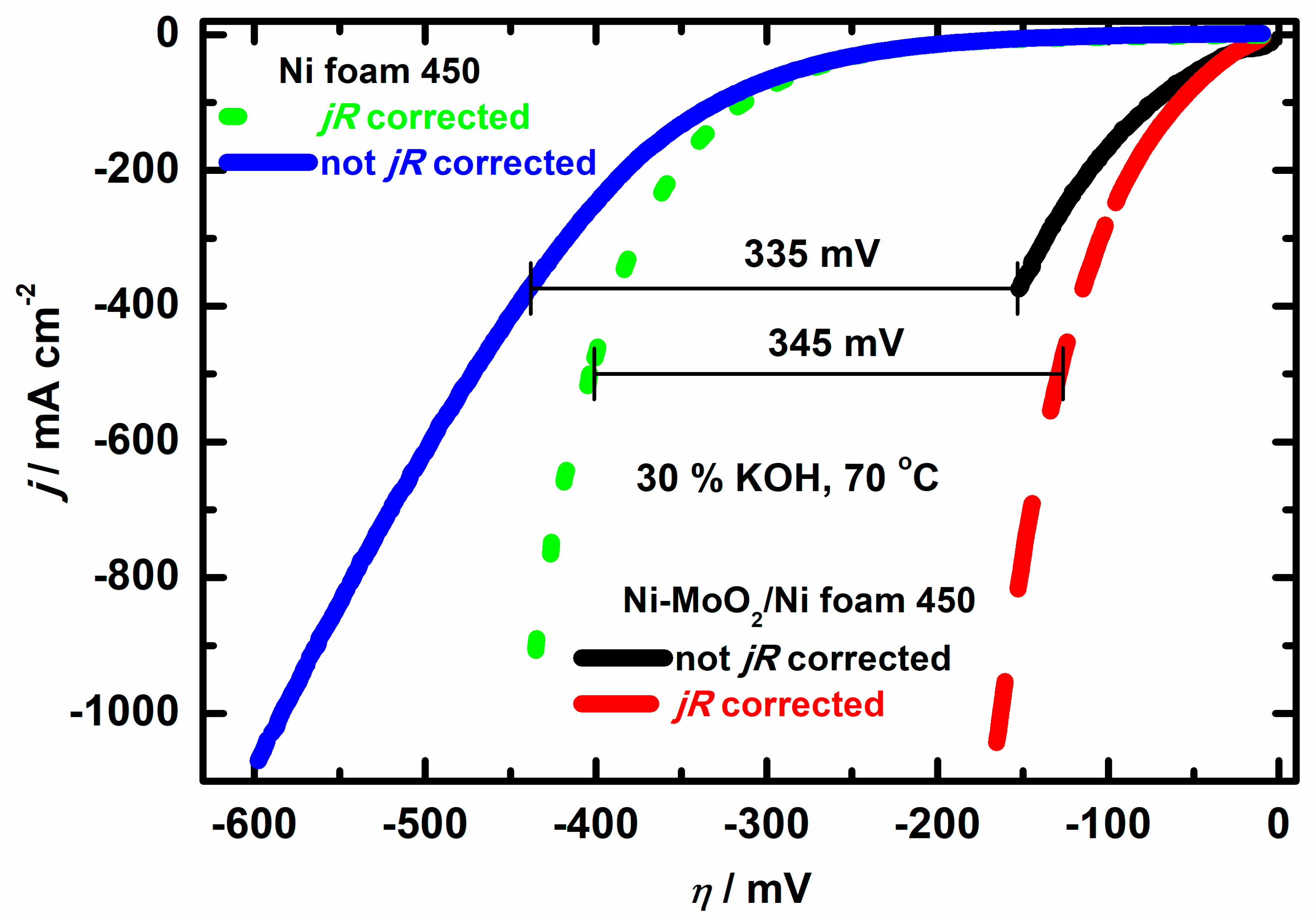
Polarization curves (j vs. η) for the HER in 30% KOH at 70 °C recorded at bare Ni foam 450 and Ni-MoO2/Ni foam 450 (Ni-MoO2 electrodeposited at –100 mAcm−2 from the bath containing 2.5 g L−1 MoO2) are presented in Figure 6. It is obvious for both electrodes that much lower overpotentials were obtained after jR drop correction. It is also obvious that the catalytic activity of Ni-MoO2/Ni foam 450 is significant, with η being 345 mV lower at j = −500 mA cm−2 compared to bare Ni foam 450. A similar difference in η (335 mV) is obtained for polarization curves recorded without the jR drop correction.
Such notable improvement of catalytic activity, compared to bare Ni foam, outlines the better performance of Ni-MoO2 catalyst than pure Ni, proving the important role of MoO2 in the intrinsic activity of the coating. Namely, as mentioned in the Introduction part, the role of molybdenum oxide species is to facilitate HER kinetics through the spillover effect. These particles cause the diffusion of the reaction intermediates ( H a d s ) formed by the Volmer reaction as they act as H a d s acceptors, leaving the nickel active sites for further hydrogen adsorption [13,14]. For this reason, the composition of the coating should be carefully tailored, as small amounts of molybdenum oxide particles contribute to the spillover effect and provide better HER activity. At the same time, a higher content of MoO2 significantly reduces the number of Ni active sites for hydrogen adsorption, reducing the coating HER activity [14].
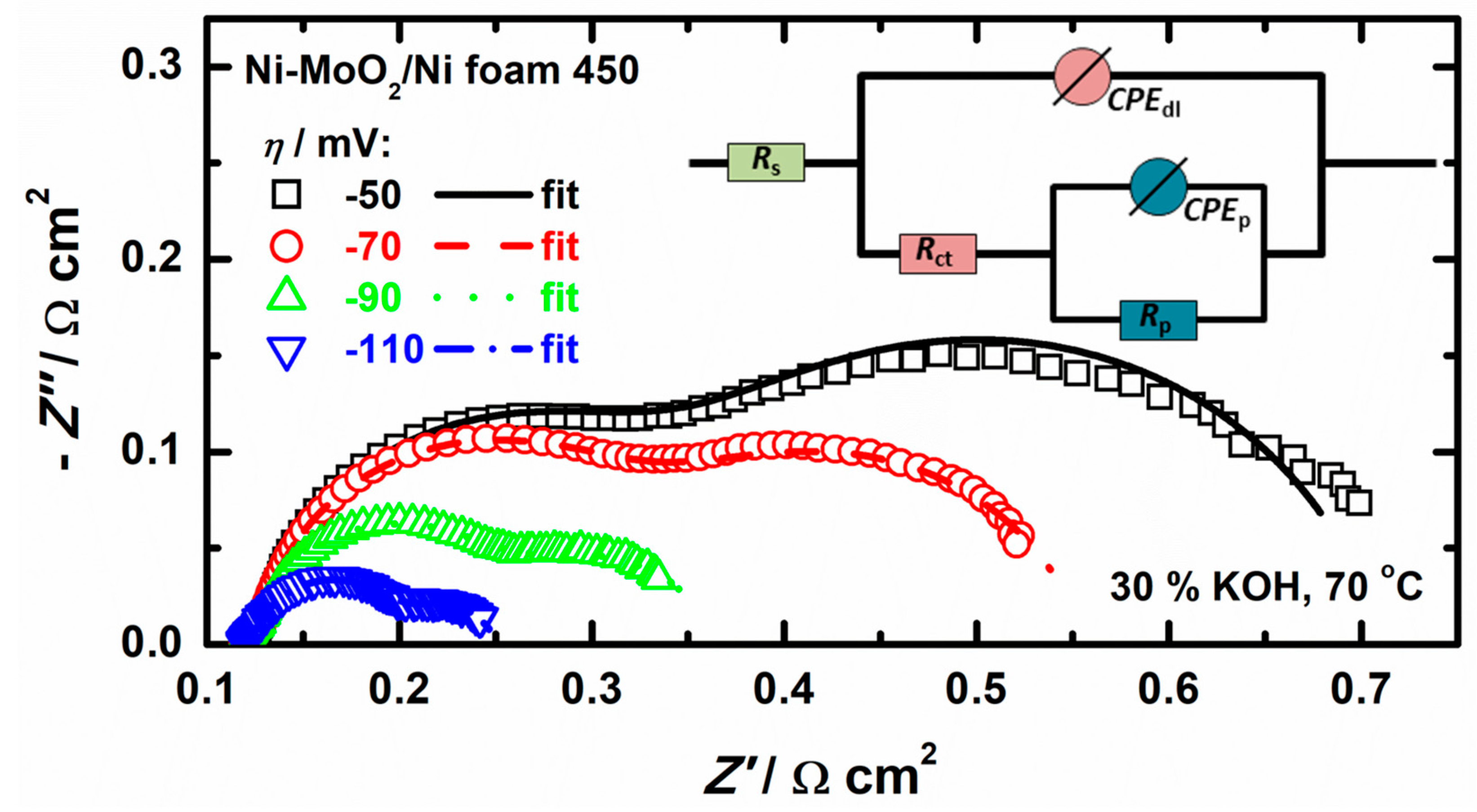
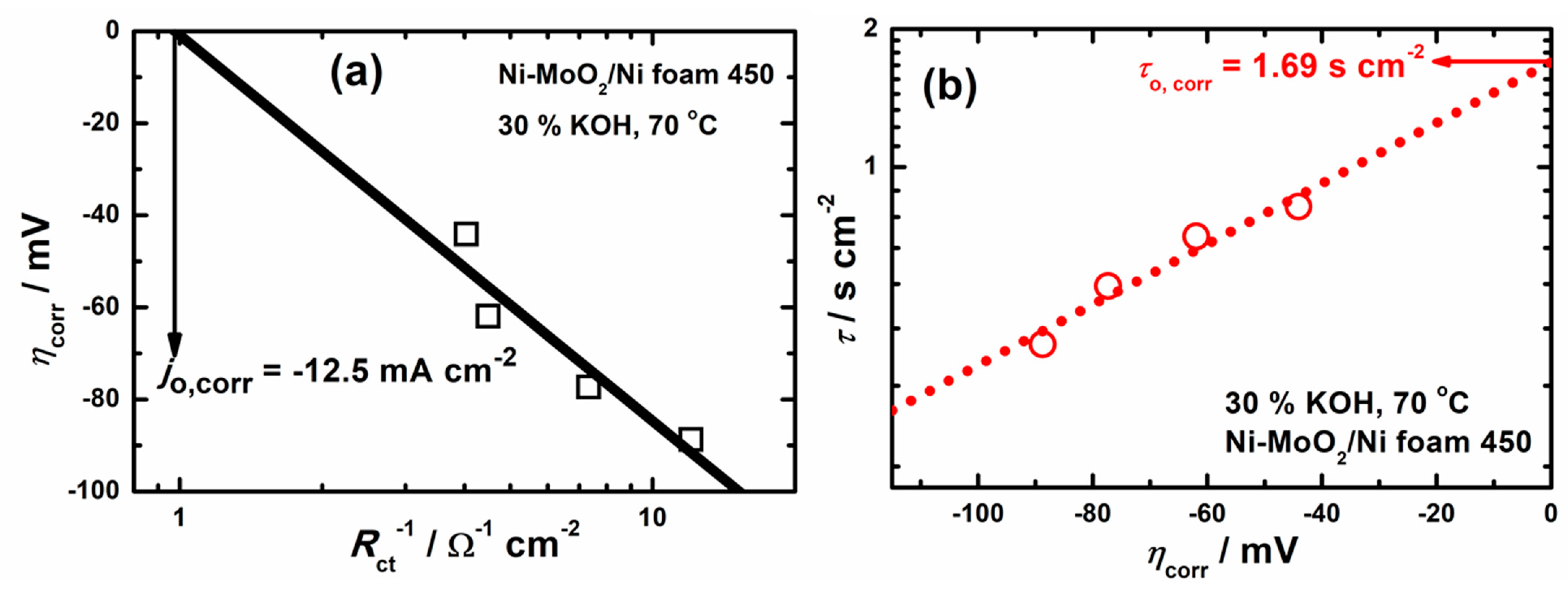
Nyquist plots for the HER at Ni-MoO2/Ni foam 450 in 30% KOH at 70 °C, recorded at η values of −50, −70, −90, and −110 mV, are shown in Figure 7. As can be seen, all Nyquist plots are characterized by the presence of two semi-circles, confirming that at elevated temperatures and high concentrations of KOH, adsorption of intermediate (Hads) depends on the potential. This process can be presented and fitted by the equivalent circuit given in the inset. For fitting EIS results, constant phase elements (CPE) had to be used, the values of the double layer capacitance (Cdl) and the pseudo-capacitance of the electrosorbed species (Cp) were calculated using equations defined in our previous papers [39,40]. The correct determination of parameters for the HER was performed using the same procedure as that explained in [39]. After calculating all the parameters (Cdl, Rct, and Cp), the values of η were corrected for the jRs drop [39], and the corresponding ηcorr vs. log(Rct−1) and logτ vs. ηcorr dependencies were plotted in Figure 8a and Figure 8b, respectively, in order to obtain the exchange current density (j0,corr) and equilibrium relaxation time (τo,corr).
It should be emphasized that high values for jo,corr, and τo are a consequence of the fact that only one side of Ni foam 450 (with an area of 0.81 cm2) has been used for the calculation of current densities (as suggested in Ref. [38] for tests in the single cells). The electrochemically active surface area must be much higher than geometric, although it was not calculated due to the lack of a reliable method to compare the surface area of bare and coated Ni foam. Even though various methods are used to determine the electrochemically active surface area of non-Pt electrodes [41,42], the question of accurate values of ideal double layer capacity for Ni foam material and the coated Ni foam complicates this calculation [5,43,44]. Considering the morphology of Ni-MoO2/Ni foam 450 (Figure 1), the presence of cracks on the top surface of the foam, and the relatively flat and thin coating inside the pores, it seems practically impossible to determine the electrochemically active surface area. In addition, using the geometric surface area is common for industrially applicable electrodes (as suggested by [38]) as one side is exposed to the membrane in a single cell; therefore, this value is used for the calculations. It should be stated that, in addition to the intrinsic activity of the coating, the increase in the electrochemically active surface area of the coated electrode due to the coating morphology contributes to the overall improved catalyst activity compared to bare Ni foam.

3.4. Investigations in a Single, Zero-Gap Membrane Cell

The single, zero-gap membrane cell is schematically presented in Figure 9a. The Teflon frame, which holds the Ni foam electrodes, is schematically presented in Figure 9b. As seen in the cathodic compartment, Ni foam serves as a current collector, while Ni-MoO2/Ni foam 450 is a catalyst. In the anodic compartment, Ni foam serves as a current collector, as well as the catalyst. The cell arrangement is as follows: end plate | current collector|cathode||anode|current collector|end plate.
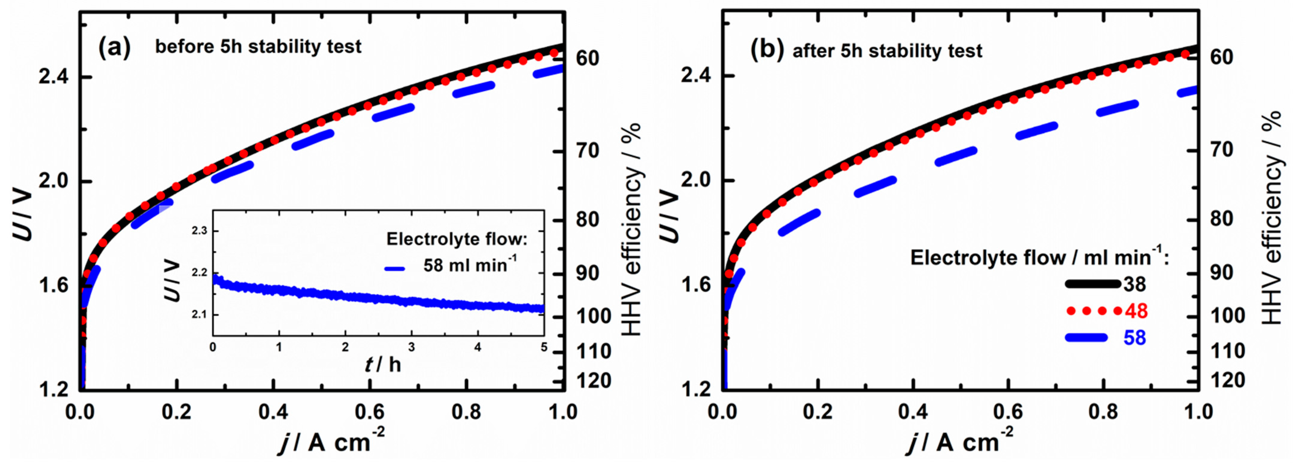
Voltage vs. current density (Uj) dependencies recorded for three flow rates in the cell composed of bare Ni 450 foam as the cathodic current collector, Ni-MoO2/Ni foam 450 as the cathode catalyst layer, and bare Ni 450 foam as a current collector and anode catalyst layer are shown in Figure 10a before- and in Figure 10b after the stability test. The Ut dependency recorded at the highest electrolyte flow during the preliminary stability test is given in the inset in Figure 10a. High heating value (HHV) efficiency, which compares the theoretically required energy to the actual energy applied for the reaction, is also displayed in Figure 10a,b, depending on the applied current density. The theoretically required energy represents the enthalpy for the water-splitting reaction, where water is in the liquid state [45]. The best results were obtained with the flow rate of 58 mL min−1 with the voltage at 500 mA cm−2 being approximately 170 mV lower after the 5 h stability test. The drop in overvoltage suggests that the surface is cleaned from the impurities collected in the air or the electrodeposition bath, and no coating detachment is noticed during the experiment.
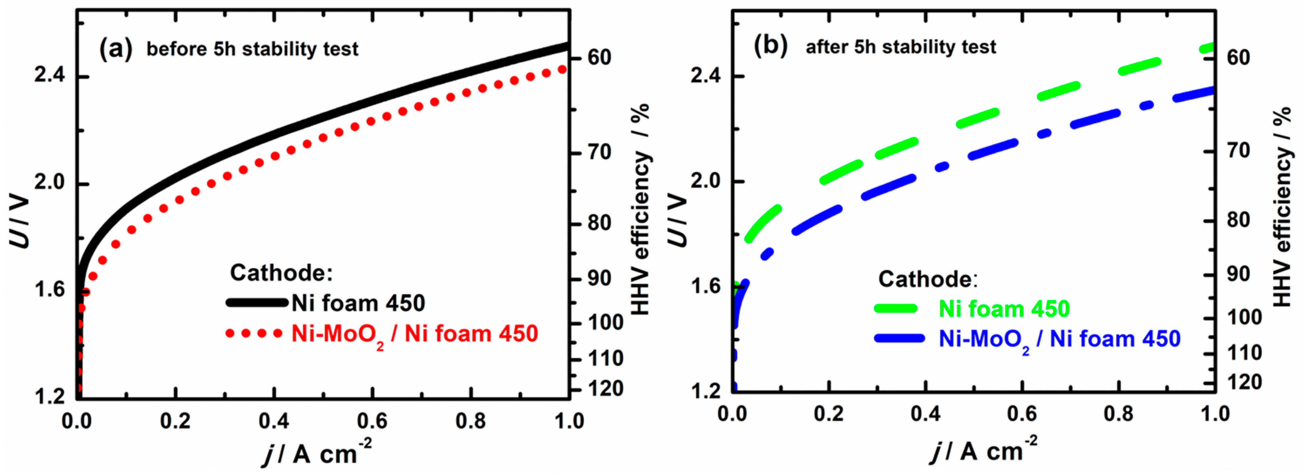
These results are compared with the cell assembly where bare Ni foam is also used as a cathode catalyst. Figure 11 shows Uj dependencies recorded for the flow rate of 58 mL min−1 before (Figure 11a) and after (Figure 11b) the preliminary stability test for cells containing bare Ni foams as cathode catalyst and Ni-MoO2/Ni foam as cathode catalyst. At the current density of 500 mA cm−2, the voltage on the cell with Ni-MoO2 cathode catalyst is lower than that with bare Ni foam cathode catalyst for 80 mV before the stability test, while after the stability test, this difference increased to 140 mV.
Comparing the results obtained in the H-cell with stagnant electrolyte (Figure 6) and single zero-gap membrane cell with electrolyte flow of 58 mL min−1 (Figure 10 and Figure 11), it is obvious that the catalytic activity of Ni-MoO2/Ni foam 450 is less pronounced in the zero-gap membrane cell (only 140 mV in comparison with 335 mV for H-cell). However, several parameters should be considered regarding different resistances present in a zero-gap cell: the construction of the zero-gap cell (presence of current collector), contact of the ZirfonTM PERL UTP 500 diaphragm with electrode surface, the flow rate of the electrolyte (limitations in active surface area of foams), etc. The simulations reported in the literature [46] also mention different additional resistances: uneven current distribution due to electrode geometry, the electrode gap (not equivalent to exact zero), bubbles in the electrolyte, concentration gradient, electrode perforations filled with stagnant bubbles, etc. Thus, more attention should be paid to designing experiments in zero-gap systems to overcome these issues and obtain more reliable data on catalyst performance.
Another issue is comparing the obtained results to other reported catalysts, as most literature refers to overpotential and cell voltage values on low current densities, such as 10 mA cm−2, which is irrelevant for industrial applications. Although Ni-Mo-based catalysts are outlined as benchmark HER catalysts in alkaline media and the most prominent replacement for Pt-based catalysts in recent review papers [47,48,49], even putting a spotlight on Ni foam and Ni mesh-supported catalysts, it is hard to compare our electrodes to other publications due to a different focus regarding the current density values. Some of the reported materials stand out: MoNi4/MoO2@Ni with an overpotential of −15 mV at −10 mA cm−2 in 1 M KOH [50], which is equal to the catalyst reported in this paper; NiS/MoO3/NF, which gives a cell voltage of 1.56 V at 10 mA cm−2 in overall water splitting [51]. These materials seem to outperform our cathodes, but the used electrolyser is a standard 2-electrode system, rather than the zero-gap used in this paper, and the results obtained in a 3-electrode cell in 1 M KOH are, by far, exceeded by the electrodes reported here. The overpotential at −10 mA cm−2 in 1 M KOH reported in that study [51] is as high as −150 mV, the same as reported for NiMo films [52]. Multimetal alloys such as NiMoCo/Ni mesh show promising results, with η10 of −13.7 mV in 1 M KOH and cell voltage of 1.44 V for overall water splitting at 10 mA cm−2, although in a standard 2-electrode system. Research that stands out regarding the applied testing conditions close to industrial [53] reports electrodeposited NiMo/NF cathodes that give a cell voltage of 1.64 V at 200 mA cm−2 in a 2-compartment electrolyzer with the NiFe/NF anode.
Given the promising results of our study, compared to other reported Ni-Mo-based catalysts, our Ni-MoO2 composite coatings electrodeposited at three-dimensional Ni substrates represent a promising material that can be tailored to respond to specific demands of zero-gap flow electrolyzer systems. The research will continue with further characterization of the obtained electrode material, more reliable stability tests, and additional optimization of synthesis parameters, including the structure of the substrate, MoO2 nanoparticle size, bath composition, optimization of experimental procedures in zero-gap arrangement, etc.

4. Conclusions

In this research, an efficient electrodeposition procedure for the production of composite Ni-MoO2 coatings on Ni foam substrate is presented. Using Ni foam with an open-pore structure and average pore size of 450 µm as a substrate, highly functional electrodes for zero-gap flow electrolyzers are obtained by determining the optimal electrodeposition parameters.
By using a Watts-type electrodeposition bath with a concentration of 2.5 g L−1 of commercially available MoO2 nanopowder with an average particle size of 100 nm and applying a constant current density of −100 mA cm−2 for 30 min, composite coating Ni-MoO2 covering the inner and outer surface of the foam is obtained. The thickness of the coating is higher at the outer surface and lower inside the pores, but the coating does not block the pore openings necessary for the electrolyte flow. An overpotential of −150 mV at −500 mA cm−2 (normalized per geometric area) in 1 M KOH at 25 °C and around −125 mV at −500 mA cm−2 in 30% KOH at 70 °C are achieved in an H-type cell with stagnant electrolyte.
When used as a cathode in a zero-gap flow cell with 30% KOH at 70 °C, this electrode provides a current density of 500 mA cm−2 with reduced overvoltage for 140 mV, compared with pure Ni foam 450 used as the cathode, showing improved catalytic performance.

Author Contributions

Conceptualization: V.D.J., M.N.K.P., and N.E.; methodology: M.N.K.P. and V.D.J.; formal analysis: V.D.J. and A.P.; electrochemical experiments: A.P., J.G., and T.R.; SEM/EDS analysis: M.B., cross-section analysis: T.R., resources: C.I.B., M.N.K.P., and N.H.; writing—original draft preparation: V.D.J. and A.P.; writing—review and editing: M.N.K.P.; supervision: M.N.K.P., V.D.J., N.E., and M.S.; project administration: C.I.B., T.R., and M.N.K.P.; funding acquisition: C.I.B. All authors have read and agreed to the published version of the manuscript.

Funding

This work was supported by the Federal Ministry of Education and Research–Germany, through the WBC2019 call–project NOVATRODES 01DS21010, and by the Ministry of Science, Technological Development, and Innovation of the Republic of Serbia (Contract No. 451-03-65/2024-03/200135 and 451-03-66/2024-03/200053). The authors would also like to acknowledge the Slovenian Research and Innovation Agency (ARIS) within the research programs P2–0393, P2-0132, I0–0003 and I0-0006 and the projects N2-0155, N2–0248, N2-0337 and J7–4636. We also acknowledge NATO Science for Peace and Security Program (Grant G5729).

Institutional Review Board Statement

Not applicable.

Informed Consent Statement

Not applicable.

Data Availability Statement

The raw data supporting the conclusions of this article will be made available by the authors upon request.

Acknowledgments

M.K.P acknowledges the support of Hielscher Inc., manufacturer of the Ultrasonic Processor UP200Ht used in the preliminary experiments of this research, in troubleshooting during the application of the probe in the electrodeposition bath, as well as providing a replacement probe upon malfunction of the original one. J.G. is grateful to the Erasmus + KA 131 mobility program, during which she stayed at the National Institute of Chemistry, Ljubljana, Slovenia, in 2023.

Conflicts of Interest

The authors declare no conflicts of interest.

References

  1. Li, Q.; Hou, Y.; Yin, J.; Xi, P. The Evolution of Hexagonal Cobalt Nanosheets for CO2 Electrochemical Reduction Reaction. Catalysts 2023, 13, 1384. [Google Scholar] [CrossRef]
  2. Koolen, C.D.; Oveisi, E.; Zhang, J.; Li, M.; Safonova, O.V.; Pedersen, J.K.; Rossmeisl, J.; Luo, W.; Züttel, A. Low-temperature non-equilibrium synthesis of anisotropic multimetallic nanosurface alloys for electrochemical CO2 reduction. Nat. Synth 2024, 3, 47–57. [Google Scholar] [CrossRef]
  3. Kuznetsova, I.; Lebedeva, O.; Kultin, D.; Mashkin, M.; Kalmykov, K.; Kustov, L. Enhancing Efficiency of Nitrate Reduction to Ammonia by Fe and Co Nanoparticle-Based Bimetallic Electrocatalyst. Int. J. Mol. Sci. 2024, 25, 7089. [Google Scholar] [CrossRef]
  4. Xiang, D.; Bao, J.; Zhang, L.; Xin, P.; Yue, C.; Naseri, A.; Wang, H.; Huang, S.; Uvdal, K.; Hu, Z. Interfacial electronic structure modulations of Au@CuS with defective Ni-doped CoS2 facilitates the electroreduction of N2 into NH3. Chem. Eng. J. 2024, 493, 152456. [Google Scholar] [CrossRef]
  5. Rocha, F.; Delmelle, R.; Georgiadis, C.; Proost, J. Effect of pore size and electrolyte flow rate on the bubble- removal efficiency of 3D pure Ni foam electrodes during alkaline water electrolysis. J. Environ. Chem. Eng. 2022, 10, 107648. [Google Scholar] [CrossRef]
  6. Wang, N.; Song, S.; Wu, W.; Deng, Z.; Tang, C. Bridging Laboratory Electrocatalysts with Industrially Relevant Alkaline Water Electrolyzers. Adv. Energy Mater. 2024, 14, 2303451. [Google Scholar] [CrossRef]
  7. Technical Targets for Liquid Alkaline Electrolysis. Available online: https://www.energy.gov/eere/fuelcells/technical-targets-liquid-alkaline-electrolysis (accessed on 20 June 2024).
  8. Clean Hydrogen JU-SRIA Key Performance Indicators (KPIs). Available online: https://www.clean-hydrogen.europa.eu/knowledge-management/strategy-map-and-key-performance-indicators/clean-hydrogen-ju-sria-key-performance-indicators-kpis_en (accessed on 18 June 2024).
  9. Buch, C.G.; Cardona, I.H.; Ortega, E.; Anton, J.G.; Herrenz, V.P. Study of the catalytic activity of 3D macroporous Ni and NiMo cathodes for hydrogen production by alkaline water electrolysis. J. Appl. Electrochem. 2016, 46, 791–803. [Google Scholar] [CrossRef]
  10. Shetty, S.; Hegde, A.C. Magnetically Induced Electrodeposition of Ni-Mo Alloy for Hydrogen Evolution Reaction. Electrocatalysis 2017, 8, 179–188. [Google Scholar] [CrossRef]
  11. Rao, D.; Wang, L.; Zhu, Y.; Guo, R.; Li, Z. Electrochemical Preparation of Ni-Mo Coated Coral-Like Cu Micro-Arrays for Electrocatalytic Hydrogen Evolution Reaction in Acidic Solution. J. Electrochem. Soc. 2016, 163, H1026–H1032. [Google Scholar] [CrossRef]
  12. Wang, X.; Su, R.; Aslan, H.; Kibsgaard, J.; Wendt, S.; Meng, L.; Dong, M.; Huang, Y.; Besenbacher, F. Tweaking the composition of NiMoZn alloy electrocatalyst for enhanced hydrogen evolution reaction performance. Nano Energy 2015, 12, 9–18. [Google Scholar] [CrossRef]
  13. Ren, B.; Li, D.; Jin, Q.; Cui, H.; Wang, C. Integrated 3D self-supported Ni decorated MoO2 nanowires as highly efficient electrocatalysts for ultra-highly stable and large-current-density hydrogen evolution. J. Mater. Chem. A 2017, 5, 24453–24461. [Google Scholar] [CrossRef]
  14. Krstajić, N.V.; Lačnjevac, U.; Jović, B.M.; Mora, S.; Jović, V.D. Non-noble metal composite cathodes for hydrogen evolution. Part II–The Ni-MoO2 coatings electrodeposited from nickel chloride-ammonium chloride bath containing MoO2 powder particles. Int. J. Hydrog. Energy 2011, 36, 6450–6461. [Google Scholar] [CrossRef]
  15. Lopez, D.E.; Niu, Y.; Yin, J.; Cooke, K.; Rees, N.V.; Palmer, R.E. Enhancement of the Hydrogen Evolution Reaction from Ni-MoS2 Hybrid Nanoclusters. ACS Catal. 2016, 6, 6008–6017. [Google Scholar] [CrossRef]
  16. Xing, Z.; Yang, X.; Asiri, A.M.; Sun, X. Three-Dimensional Structures of MoS2@Ni Core/Shell Nanosheets Array toward Synergetic Electrocatalytic Water Splitting. ACS Appl. Mater. Interfaces 2016, 8, 14521–14526. [Google Scholar] [CrossRef] [PubMed]
  17. Jiang, J.; Gao, M.; Sheng, W.; Yan, Y. Hollow Chevrel-Phase NiMo3S4 for Hydrogen Evolution in Alkaline Electrolytes. Angew. Chem. Int. Ed. 2016, 55, 15240–15245. [Google Scholar] [CrossRef]
  18. Guo, J.; Zhang, X.; Sun, Y.; Tang, L.; Zhang, X. NiMoS3 Nanorods as pH-Tolerant Electrocatalyst for Efficient Hydrogen Evolution. ACS Sustain. Chem. Eng. 2017, 5, 9006–9013. [Google Scholar] [CrossRef]
  19. Xu, W.; Fan, G.; Zhu, S.; Liang, Y.; Cui, Z.; Li, Z.; Jiang, H.; Wu, S.; Cheng, F. Electronic structure modulation of nanoporous cobalt phosphide by carbon doping for alkaline hydrogen evolution reaction. Adv. Funct. Mater. 2021, 31, 2107333. [Google Scholar] [CrossRef]
  20. Huang, Y.; Hu, L.; Liu, R.; Hu, Y.; Xiong, T.; Qiu, W.; Balogun, M.S.; Pan, A.; Tong, Y. Nitrogen treatment generates tunable nanohybridization of Ni5P4 nanosheets with nickel hydr(oxy)oxides for efficient hydrogen production in alkaline, seawater and acidic media. Appl. Catal. B 2019, 251, 181–194. [Google Scholar] [CrossRef]
  21. Zhuang, L.; Li, S.; Li, J.; Wang, K.; Guan, Z.; Liang, C.; Xu, Z. Recent Advances on Hydrogen Evolution and Oxygen Evolution Catalysts for Direct Seawater Splitting. Coatings 2022, 12, 659. [Google Scholar] [CrossRef]
  22. Ashby, M.F.; Evans, A.G.; Fleck, N.A.; Gibson, L.J.; Hutchinson, J.W.; Wadley, H.N.G. Metal Foams: A Design Guide; Butterworth-Heinemann: Woburn, MA, USA, 2000; pp. 6–20. [Google Scholar]
  23. Gojgić, J.D.; Petričević, A.M.; Rauscher, T.; Bernäcker, C.I.; Weißgärber, T.; Pavko, L.; Vasilić, R.; Krstajić Pajić, M.N.; Jović, V.D. Hydrogen evolution at Ni foam electrodes and Ni-Sn coated Ni foam electrodes. Appl. Catal. A Gen. 2023, 663, 119312. [Google Scholar] [CrossRef]
  24. Jakšic, M.M. Electrocatalysis of hydrogen evolution in the light of the brewer-engel theory for bonding in metals and intermetallic phases. Electrochim. Acta 1984, 29, 1539–1550. [Google Scholar] [CrossRef]
  25. Hashimoto, K.; Sasaki, T.; Meguro, S.; Asami, K. Nanocrystalline electrodeposited Ni-Mo-C cathodes for hydrogen production. Mater. Sci. Eng. A 2004, 375–377, 942–945. [Google Scholar] [CrossRef]
  26. Niedbała, J.; Budniok, A.; Łagiewka, E. Hydrogen evolution on the polyethylene-modified Ni-Mo composite layers. Thin Solid Film. 2008, 516, 6191–6196. [Google Scholar] [CrossRef]
  27. Aaboubi, O. Hydrogen evolution activity of Ni-Mo coating electrodeposited under magnetic field control. Int. J. Hydrog. Energy 2011, 36, 4702–4709. [Google Scholar] [CrossRef]
  28. Jović, V.D.; Lačnjevac, U.; Jović, B.M.; Krstajić, N.V. Service life test of non-noble metal composite cathodes for hydrogen evolution in sodium hydroxide solution. Electrochim. Acta 2012, 63, 124–130. [Google Scholar] [CrossRef]
  29. Jović, V.D.; Krstajić, N.V.; Rauscher, T. Electrodeposited Ni-based, non-noble metal cathodes for hydrogen evolution reaction in alkaline solutions. In Advances in Energy Research; Acosta, M.J., Ed.; Nova Science Publishers, Inc.: Hauppauge, NY, USA, 2024; Volume 39, pp. 97–184. [Google Scholar]
  30. Zheng, H.Y.; An, M.Z. Electrodeposition of Zn-Ni-Al2O3 nanocomposite coatings under ultrasound conditions. J. Alloys Compd. 2008, 459, 548–552. [Google Scholar] [CrossRef]
  31. Katamipour, A.; Farzam, M.; Danaee, I. Effects of sonication on anticorrosive and mechanical properties of electrodeposited Ni-Zn-TiO2 nanocomposite coatings. Surf. Coat. Technol. 2014, 254, 358–363. [Google Scholar] [CrossRef]
  32. Lecina, G.E.; Urrutia, G.I.; Diez, J.A.; Fornell, J.; Pellicer, E.; Sort, J. Codeposition of inorganic fullerene-like WS2 nanoparticles in an electrodeposited nickel matrix under the influence of ultrasonic agitation. Electrochim. Acta. 2013, 114, 859–867. [Google Scholar] [CrossRef]
  33. Lecina, G.E.; Urrutia, G.I.; Diez, J.A.; Morgiel, J.; Indyka, P. A comparative study of the effect of mechanical and ultrasound agitation on the properties of electrodeposited Ni/Al2O3 nanocomposite coatings. Surf. Coat. Technol. 2012, 206, 2998–3005. [Google Scholar] [CrossRef]
  34. Shourgeshty, M.; Aliofkhazraei, M.; Karimzadeh, A. Study on functionally graded Zn-Ni-Al2O3 coatings fabricated by pulse-electrodeposition. Surf. Eng. 2018, 35, 167–176. [Google Scholar] [CrossRef]
  35. Exbrayat, L.; Rebere, C.; Eyame, R.N.; Steyer, P.; Creus, J. Corrosion behaviour in saline solution of pulsed-electrodeposited zinc-nickel-ceria nanocomposite coatings. Mater. Corros. 2017, 68, 1129–1142. [Google Scholar] [CrossRef]
  36. Zanella, C.; Lekka, M.; Rossi, S.; Deflorian, F. Study of the influence of sonication during the electrodeposition of nickel matrix nanocomposite coatings on the protective properties. Corros. Rev. 2011, 29, 253–260. [Google Scholar] [CrossRef]
  37. Chase, L.L. Optical properties of CrO2 and MoO2 from 0.1 to 6 eV. Phys. Rev. B 1974, 10, 2226–2231. [Google Scholar] [CrossRef]
  38. Malkow, T.; Pilenga, A.; Tsotridis, G.; De Marco, G. EU Harmonised Polarisation Curve Test Method for Low-Temperature Water Electrolysis; Publications Office of the European Union: Luxembourg, 2018. [Google Scholar]
  39. Gojgić, J.D.; Petričević, A.M.; Krstajić Pajić, M.N.; Jović, V.D. Correct determination of the hydrogen evolution reaction pa-rameters at Ni foam electrode modified by electrodeposited Ni-Sn alloy layer. Zaštita Mater. 2024, 65, 3–10. [Google Scholar]
  40. Jović, V.D. Calculation of a pure double layer capacitance from a constant phase element in the impedance measurements. Zaštita Mater. 2022, 63, 50–57. [Google Scholar] [CrossRef]
  41. Obradović, M.D.; Gojković, S.L.J. Challenges in determining the electrochemically active surface area of Ni-oxides in the oxygen evolution reaction. J. Electroanal. Chem. 2022, 918, 116479. [Google Scholar] [CrossRef]
  42. Cossar, E.; Houache, M.S.E.; Zhang, Z.; Baranova, E.A. Comparison of electrochemical active surface area methods for various nickel nanostructures. J. Electroanal. Chem. 2020, 870, 114246. [Google Scholar] [CrossRef]
  43. McCrory, C.C.L.; Jung, S.; Peters, J.C.; Jaramillo, T.F. Benchmarking heterogeneous electrocatalysts for the oxygen evolution reaction. J. Am. Chem. Soc. 2013, 135, 16977–16987. [Google Scholar] [CrossRef]
  44. McCrory, C.C.L.; Jung, S.; Ferrer, I.M.; Chatman, S.M.; Peters, J.C.; Jaramillo, T.F. Benchmarking Hydrogen Evolving Reaction and Oxygen Evolving Reaction Electrocatalysts for Solar Water Splitting Devices. J. Am. Chem. Soc. 2015, 137, 4347–4357. [Google Scholar] [CrossRef]
  45. Babic, U.; Suermann, M.; Buchi, F.N.; Gubler, L.; Schmidta, T.J. Review: Identifying Critical Gaps for Polymer Electrolyte WaterElectrolysis Development. J. Electrochem. Soc. 2017, 164, F387–F399. [Google Scholar] [CrossRef]
  46. De Groot, M.T.; Vremana, A.W. Ohmic resistance in zero gap alkaline electrolysis with a Zirfon diaphragm. Electrochim. Acta 2021, 369, 137684. [Google Scholar] [CrossRef]
  47. Tian, X.; Zhao, P.; Sheng, W. Hydrogen Evolution and Oxidation: Mechanistic Studies and Material Advances. Adv. Mater. 2019, 31, 1808066. [Google Scholar] [CrossRef] [PubMed]
  48. Zhang, E.; Song, W. Review—Self-Supporting Electrocatalysts for HER in Alkaline Water Electrolysis. J. Electrochem. Soc. 2024, 171, 052503. [Google Scholar] [CrossRef]
  49. Ďurovič, M.; Hnát, J.; Bouzek, K. Electrocatalysts for the hydrogen evolution reaction in alkaline and neutral media. A comparative review. J. Power Sources 2021, 493, 229708. [Google Scholar] [CrossRef]
  50. Zhang, J.; Wang, T.; Liu, P.; Liao, Z.; Liu, S.; Zhuang, X.; Chen, M.; Zschech, E.; Feng, X. Efficient hydrogen production on MoNi4 electrocatalysts with fast water dissociation kinetics. Nat. Commun. 2017, 8, 15437. [Google Scholar] [CrossRef]
  51. Jin, L.; Xu, H.; Wang, C.; Wang, Y.; Shang, H.; Du, Y. Multi-dimensional collaboration promotes the catalytic performance of 1D MoO3 nanorods decorated with 2D NiS nanosheets for efficient water splitting. Nanoscale 2020, 12, 21850. [Google Scholar] [CrossRef] [PubMed]
  52. Bao, F.; Kemppainen, E.; Dorbandt, I.; Bors, R.; Xi, F.; Schlatmann, R.; van de Krol, R.; Calnan, S. Understanding the Hydrogen Evolution Reaction Kinetics of Electrodeposited Nickel-Molybdenum in Acidic, Near-Neutral, and Alkaline Conditions. ChemElectroChem 2021, 8, 195. [Google Scholar] [CrossRef]
  53. Tang, Z.; Fu, Y.; Zhao, K.; Zhu, J.; Liang, H.; Lin, S.; Song, H.; Wu, W.; Zhang, X.; Zheng, C.; et al. Electrodeposited large-area nickel-alloy electrocatalysts for alkaline hydrogen evolution under industrially relevant conditions. J. Alloys Compd. 2024, 975, 172978. [Google Scholar] [CrossRef]
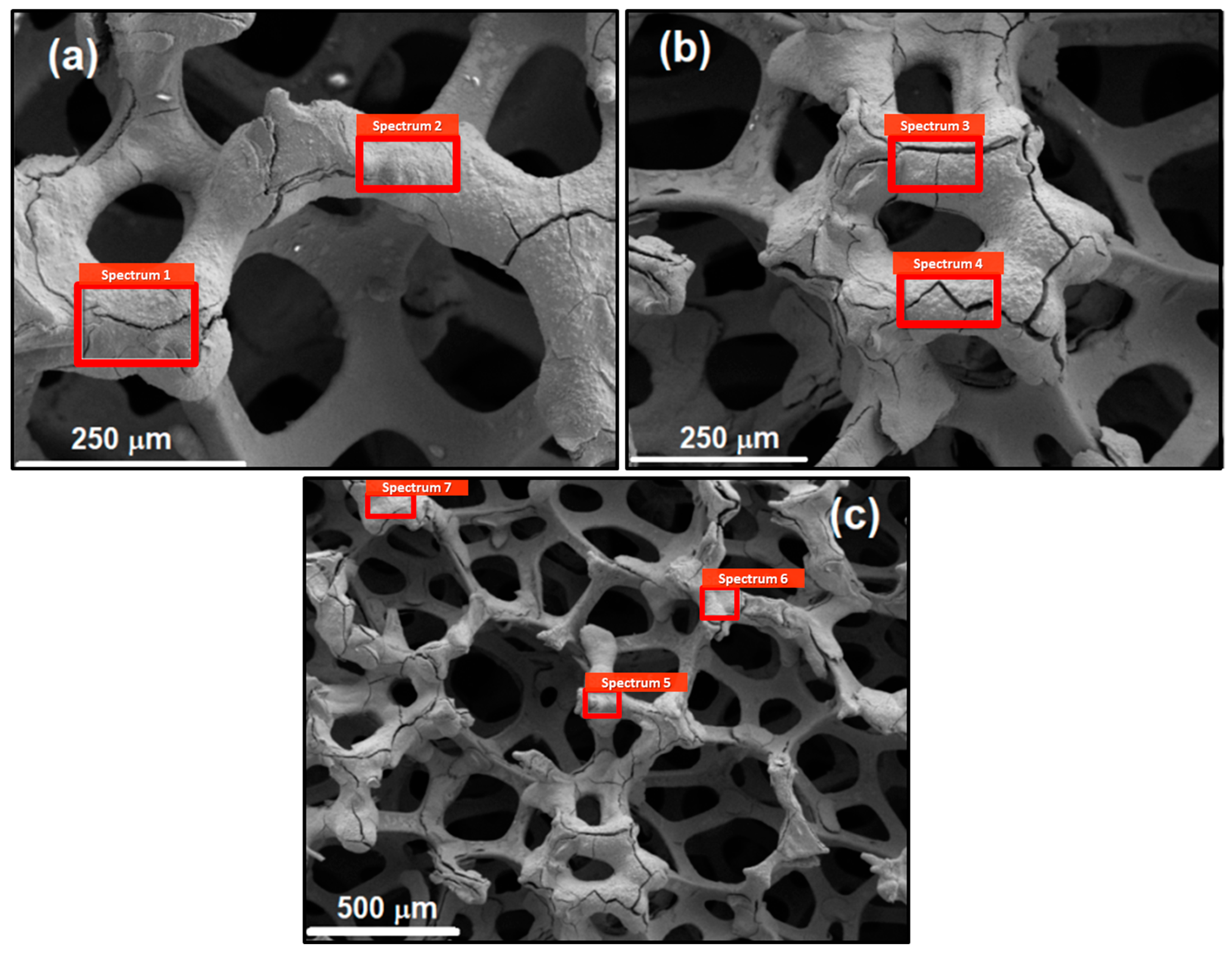
Figure 1. SEM-EDS analysis of Ni-MoO2/Ni foam 450 samples electrodeposited at different current densities: (a) jdep = −50 mA cm−2; (b,c) jdep = −100 mA cm−2 at different magnifications.
Coatings 14 01026 g001
Figure 2. SEM microphotographs of Ni-MoO2/Ni foam 450 sample surface.
Coatings 14 01026 g002
Figure 3. Light microscopy of the sample 1 cross-section.
Coatings 14 01026 g003
Figure 4. EDS analysis of a cross-section of certain Ni struts, (a,b), placed at the surface of the Ni foam 450 (sample 2). Composition data acquired at specific positions 1 to 5 (a), and 1–4 (b) are presented in Table 2.
Coatings 14 01026 g004
Figure 5. Polarization curves for all Ni-MoO2/Ni foam 450 samples recorded in 1.0 M KOH at 25 °C: (a) jη dependencies as a function of MoO2 concentration (jdep = −50 mA cm−2); (b) jη dependencies as a function of jdep (2.5 g L−1 MoO2).
Coatings 14 01026 g005
Figure 6. HER polarization curves (j vs. η) in 30% KOH at 70 °C recorded at bare Ni foam 450 and Ni-MoO2/Ni foam 450 with and without jR correction.
Coatings 14 01026 g006
Figure 7. Nyquist plots for the HER in 30% KOH at 70 °C recorded at Ni-MoO2/Ni foam 450 electrode at different applied overpotentials: η = −50 mV; η = −70 mV; η = −90 mV; η = −110 mV; with corresponding fits obtained using the equivalent circuit given in inset.
Coatings 14 01026 g007
Figure 8. Dependencies ηcorr vs. log(Rct−1) (a) and log τ vs. ηcorr (b) for the HER in 30% KOH at 70 °C recorded at Ni-MoO2/Ni foam 450 electrode.
Coatings 14 01026 g008
Figure 9. (a) Schematic presentation of a zero-gap membrane cell. (b) Schematic presentation of a Teflon frame holder.
Coatings 14 01026 g009
Figure 10. Voltage vs. current density (Uj) dependencies recorded in 30% KOH at 70 °C for three flow rates before (a) and after (b) the stability test, with Ut dependency recorded during the 5 h stability test at 500 mA cm−2, for electrolyte flow of 58 mL min−1 presented as inset in (a), and the legend presented in (b). Cell arrangement: Ni end plate|Ni foam 450|Ni-MoO2/Ni foam 450||Ni foam 450|Ni foam 450|Ni end plate.
Coatings 14 01026 g010
Figure 11. Uj dependencies recorded for the flow rate of 58 mL min−1 before (a) and after (b) the 5 h stability test for cells containing bare Ni foam as cathode and Ni-MoO2/Ni foam as cathode.
Coatings 14 01026 g011
Table 1. Compositions of samples at analysis points marked in Figure 1a–c.
FigureSpectrum No.at.% Moat.% Niat.% O
1a112.741.945.4
212.425.662.0
1b312.351.036.7
413.551.135.4
1c516.516.766.8
610.361.028.7
711.160.128.8
Table 2. EDS analysis at specific positions of Ni struts and Ni-MoO2 coatings of sample 2.
Spectrum
Position
at.% Niat.% Moat.% Oat.% Niat.% Moat.% O
Figure 4aFigure 4b
1100 100
2100 100
390.149.86 17.813.5178.69
488.4411.56 93.326.68
520.683.5575.77
Disclaimer/Publisher’s Note: The statements, opinions and data contained in all publications are solely those of the individual author(s) and contributor(s) and not of MDPI and/or the editor(s). MDPI and/or the editor(s) disclaim responsibility for any injury to people or property resulting from any ideas, methods, instructions or products referred to in the content.