Article

High-Temperature Hot Corrosion Resistance of CrAl/NiCoCrAlY/AlSiY Gradient Composite Coating on TiAl Alloy

1
College of Materials Science and Technology, Nanjing University of Aeronautics and Astronautics, Nanjing 210016, China
2
Wuxi Research Institute, Nanjing University of Aeronautics and Astronautics, Nanjing 210016, China
3
National Key Laboratory of Advanced Composites, AECC Beijing Institute of Aeronautical Materials, Beijing 100095, China
4
Institute of Wenzhou, Zhejiang University, Wenzhou 325006, China
*
Author to whom correspondence should be addressed.
Coatings 2024, 14(8), 1067; https://doi.org/10.3390/coatings14081067 (registering DOI)
Submission received: 30 June 2024 / Revised: 18 July 2024 / Accepted: 9 August 2024 / Published: 20 August 2024
(This article belongs to the Special Issue High-Temperature Corrosion and Oxidation of Metals and Alloys)

Abstract

:
TiAl alloys are used in high-temperature components such as the turbine blades of aeroengines because of their excellent properties. However, TiAl alloys are prone to thermal corrosion when in near-ocean service. In order to solve this problem, a hot-corrosion-resistant CrAl/NiCoCrAlY/AlSiY gradient composite coating was prepared on the surface of the TiAl alloy. The phase composition and morphology of the coating were analyzed. Hot corrosion tests of the traditional NiCoCrAlY coating and CrAl/NiCoCrAlY/AlSiY gradient composite coating on a TiAl substrate were performed. The samples were coated with 75%Na2SO4 + 25%NaCl salt film and treated at 950 °C for 100 h, and the corrosion products were analyzed. The results indicate that compared with the TiAl substrate and traditional NiCoCrAlY-coated samples, the composite coating showed better hot corrosion resistance, only slightly cracking, and no corrosion loss occurred. This is mainly because the continuous Al2O3 layer can effectively resist the damage caused by the melting reaction in salt, and the Cr-rich layer can not only slow the mutual diffusion of elements but also generate a good corrosion resistance chromium oxide protective layer under serious corrosion. Moreover, the corrosion mechanism of the TiAl substrate, traditional NiCoCrAlY coating, and experimental composite coating was analyzed in detail.

1. Introduction

TiAl intermetallic compounds are used in high-temperature components such as engines as structural alloys because of their high specific strength, good creep resistance, low density, and high-temperature oxidation resistance [1,2]. Engine components made of TiAl alloy are sometimes used in ocean or low-altitude environments over the ocean; the generally accepted temperature is 550–800 °C [3,4,5,6]. NaCl in the ocean atmosphere may be carried by water vapor near the turbine blades, and it easily reacts with sulfur impurities in the fuel at high temperatures [7]. Therefore, the salt film composed of NaCl and Na2SO4 is attached to the surface layer of the alloy component, and hot corrosion occurs [8,9]. During the hot corrosion of metal, also known as molten salt accelerated oxidation, in the presence of sulfate, carbonate, and other environments, the workpiece reacts with the surface salt, which can be regarded as a more severe form of oxidation in the service environment. The high-temperature oxidation rate of the TiAl alloy will be accelerated in an atmosphere of NaCl, and due to the presence of volatile substances, like NaCl, Cl2, and Na2Cl2, a loose and porous oxide film will be formed on the alloy surface [10]. The TiAl alloy corrodes in NaCl + Na2SO4 mixed salt at 800 °C, resulting in a large number of cracks, corrosion pits, and spalling on the surface [11].
To improve the hot corrosion resistance of the TiAl alloy, researchers have mainly focused on the overall alloying and improvements in the surface coating. Although the overall alloying can effectively improve the oxidation and corrosion resistance of the alloy, it changes the mechanical properties of the TiAl alloy. Therefore, the surface coating modification of the TiAl alloy has received more attention. NiCoCrAlY coating is a common protective coating on the surface of the TiAl alloy to improve high-temperature performance due to the NiCoCrAlY protective layer, forming a dense alumina layer in a high-temperature environment, and Al and Cr elements in the coating can improve the hot corrosion resistance of the TiAl substrate [12,13,14]. However, Al is gradually consumed with an increase in high-temperature service time due to the low content of Al; non-protective oxides of spinel containing elements such as Ni and Cr will be formed. In addition, under the long-term high-temperature service condition, a serious element interdiffusion phenomenon between the NiCoCrAlY coating and the TiAl alloy will be generated, which leads to more defects between the coating and the substrate.
Due to the high-temperature behavior, failure mechanism, and modification method of the NiCoCrAlY coating on the surface of the TiAl alloy, a CrAl/NiCoCrAlY/AlSiY gradient composite coating, Al-rich on the outside and Cr-rich on the inside, was designed to improve the high-temperature performance of the traditional NiCoCrAlY coating. The main part of the gradient composite coating is the NiCoCrAlY layer prepared via atmospheric plasma spraying (APS); this preparative technique has a stable process, low cost, and wide application. In view of problems such as the excessive Al consumption of the traditional NiCoCrAlY coating, the Al-rich layer was prepared on the surface of the NiCoCrAl coating, which provides a sufficient Al source for the formation of a continuous Al2O3 film on the surface coating. To improve the coating quality, a small amount of Si and Y active elements were added to the Al-rich layer [15,16,17], which can enhance the formation of the oxide binding force on the surface. The Al-rich layer was prepared via magnetron sputtering technology. The main feature of this technology is that the element composition is controllable, and the prepared coating is dense, which plays the role of blocking oxygen from entering the coating. Moreover, the Cr-rich layer was prepared in the lower part of the NiCoCrAlY layer to solve the problem of increasing defects and deteriorating properties between the coating and substrate due to element diffusion between the NiCoCrAlY coating and the TiAl alloy at high temperatures. The Cr-rich layer was prepared via high-velocity oxy-fuel (HVOF) technology; the layer consists of a high content of Cr and a small content of Al [18].
In summary, a CrAl/NiCoCrAlY/AlSiY gradient composite coating, Cr-rich on the bottom and Al-rich on the top, was designed and prepared. The problem of Al and Cr consumption of the traditional NiCoCrAlY coating on the TiAl alloy at high temperatures was solved. The phase structure and morphology of the coating were studied systematically. Hot corrosion tests of the TiAl alloy substrate, traditional NiCoCrAlY coating, and CrAl/NiCoCrAlY/AlSiY gradient composite coating with NaCl + Na2SO4 at 950 °C were performed. The phase structure, morphology, and corrosion mechanism of the corrosion products were discussed in detail.

2. Experimental Section

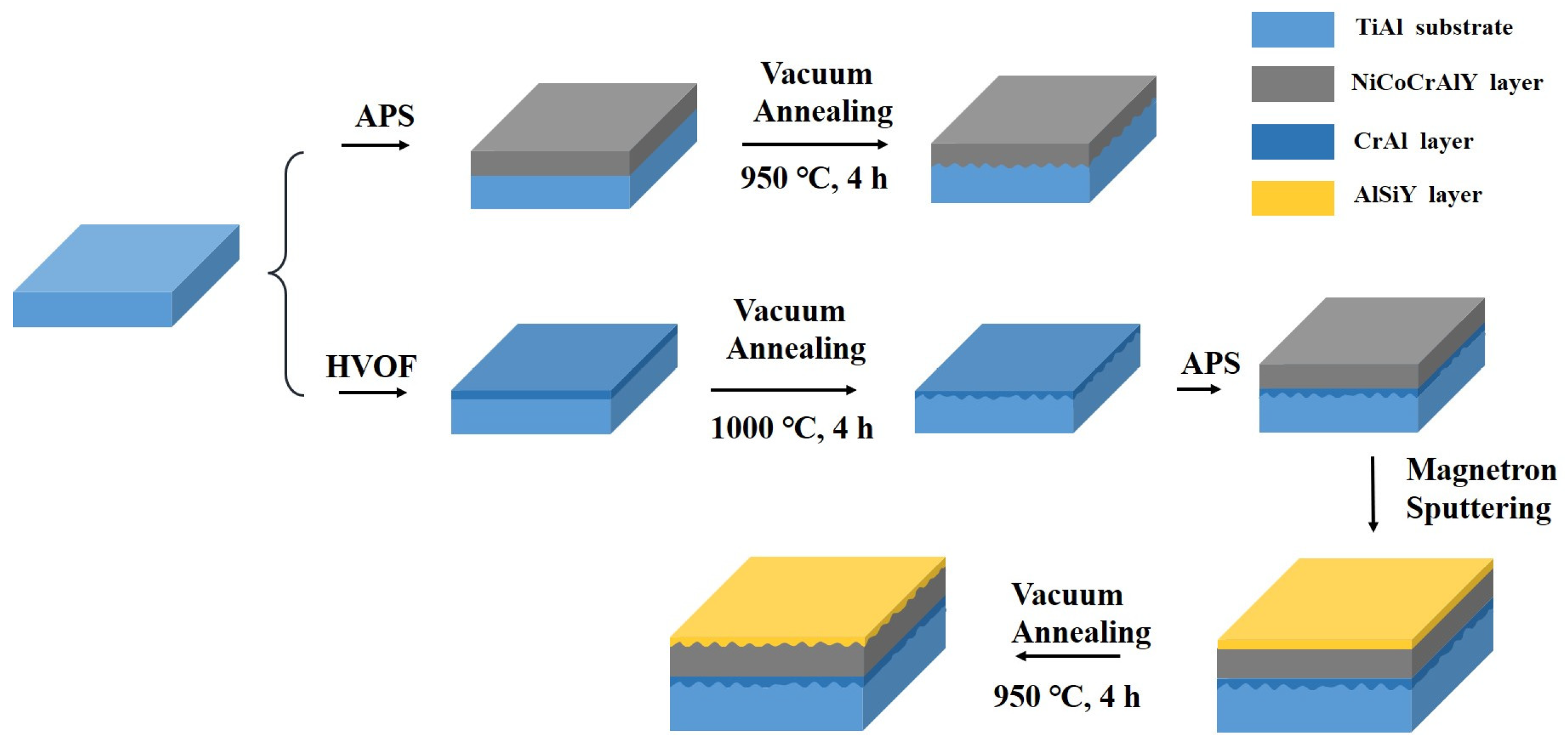
2.1. Preparation of CrAl/NiCoCrAlY/AlSiY Coating

A γ-TiAl alloy with a chemical composition of Ti−46.5Al−1Cr−0.6 V (at %) was used as substrate. The TiAl alloy ingot was cut into blocks with a size of 10 mm × 10 mm × 5 mm. First, the samples were ground with sandpaper and polished until the sample surface was bright. After ultrasonic cleaning, the samples were stored in alcohol. For the preparation of CrAl layer, Cr and Al (purity 99.9%) powders were selected, and the proportion of Cr−10Al (at. %) was mechanically mixed. In the ball milling process, argon gas was used to prevent rapid oxidation of Cr and Al. Ball milling was conducted for 5 h at a speed of 300 r/min. The NiCoCrAlY layer was sprayed using NiCoCrAlY integrated powder produced by Xingtai Zhongzhou Alloy Material Company with particle size about 5–15 μm. In this experiment, DBY501 magnetron sputtering equipment was used to prepare the AlSiY layer on the top surface of the gradient composite coating. First, the samples sprayed with CrAl/NiCoCrAlY layer on the TiAl substrate were soaked in anhydrous ethanol; they were cleaned by ultrasonic cleaning machine and then dried for use. The Al−4.5Si−1.2Y (at.%) target with a diameter of 100 mm and a thickness of 4 mm was used as the sputtering source. The specific process parameters for each layer are listed in Table 1, and a schematic diagram of CrAl/NiCoCrAlY/AlSiY gradient composite coating preparation process is shown in Figure 1.

2.2. Characterization

The phase structure of coatings was analyzed using an X-ray diffractometer (XRD, Bruker D8 Discover) with a scan speed of 8°/min. Surface and cross-section micromorphology were observed using a scanning electron microscope (SEM, TESCAN Brno LYRA3GM). An energy-dispersive spectroscopy detector (EDS, EDAX Genesis) was employed to quantitatively analyze the elemental composition of the surface and cross-sectional morphology of the samples. Prior to cross-sectional morphology observation by SEM and EDS, the samples were cold-embedded in a mixed sol of epoxy resin and curing agent. Subsequently, the cross-sections of the samples were ground, polished, ultrasonically cleaned, and dried for characterization.

2.3. Hot Corrosion Tests

The substrates and coatings underwent high-temperature molten salt corrosion tests at 950 °C for 100 h. Initially, a supersaturated solution of 75% Na2SO4 + 25% NaCl (wt.%) was prepared. A layer of salt film was evenly applied to the surface of the samples, and the samples were measured again to ensure that the salt film mass was 2–3 mg/cm2 and then placed in a resistance furnace. After 10 h of corrosion at high temperature, the furnace was cooled to room temperature. The salt film on the surface of the samples was washed off with boiling water and dried, and the samples were weighed and the results recorded.

3. Results

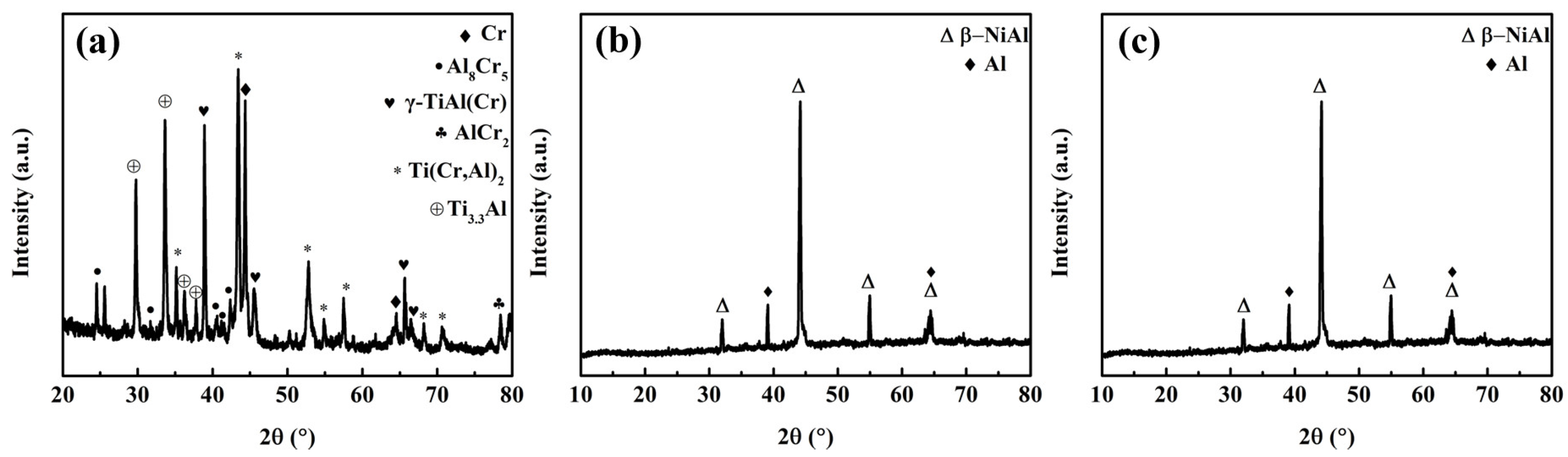
3.1. Phase Structure of CrAl/NiCoCrAlY/AlSiY Coating

As shown in Figure 2a, the main phase of the CrAl layer was composed of γ-TiAl(Cr), Ti(Cr,Al)2, and Ti3.3Al. Additionally, small amount of Cr, AlCr2, and Al8Cr5 compounds existed. Among these, Cr and Al8Cr5 provided Cr sources for the coating to generate Cr2O3. The Ti(Cr,Al)2 was formed by the mixture of δ-Ti(Cr,Al)2 and γ-Ti(Cr,Al)2, where δ belonged to the ordered hexagonal high-temperature phase. This phase was retained at room temperature with rapid cooling, as its transformation into the face-centered cubic (FCC) γ phase was slow. The dense structure of this phase played a role in slowing down the rate of interdiffusion of elements between the coating and the substrate during the high-temperature corrosion process. The NiCoCrAY coating (Figure 2b) was mainly composed of γ-Ni and γ’-Ni3Al phases and σ-NiCoCr phase, where the FCC γ/γ’ phase was a solid solution phase of Cr and Co [19]. As shown in Figure 2c, the main phases of the AlSiY coating were β-NiAl and Al. No obvious diffraction peaks of the phases containing elements Si and Y were found, due to the small content of Si and Y. β-NiAl provided the Al source during the high-temperatures service of the coating and was also the most stable of Ni-Al compounds [20].

3.2. Morphology CrAl/NiCoCrAlY/AlSiY Coating

Figure 3 shows the surface morphology of CrAl, NiCoCrAlY, and AlSiY layers prepared on the TiAl substrate. As shown in Figure 3a, the sprayed CrAl layer exhibits a relatively uniform and dense stacked morphology with fewer pores. On the annealed surface, a uniform rod-like structure was observed, which was relatively dense in the enlarged image (Figure 3b). Figure 3c depicts the surface morphology of the NiCoCrAlY layer. The sprayed state of the NiCoCrAlY coating before annealing showed an obvious stacking morphology. During plasma spraying, the raw powders were heated to a molten state, and the high-speed particle flow was generated and directly collided with the sample surface at high energy. At this point, the raw material particles flattened horizontally and deposited during the subsequent cooling process. Due to the high speed of coating formation, the NiCoCrAlY layer formed a layered structure, mixing the morphology of molten raw materials and non-molten particles and containing more obvious pores on the surface. The annealed coating (Figure 3d) developed a relatively uniform short cylindrical structure, and the partial enlarged view showing that pores may exist between the structures. Figure 3e shows the surface morphology of the AlSiY layer prepared by magnetron sputtering technology on NiCoCrAlY. A few large particles were present on the sputtered surface, but the coating was generally uniform and dense without obvious defect morphology. The annealed AlSiY surface (Figure 3f) formed a relatively dense equiaxial crystal structure, which appeared relatively uniform and dense in the enlarged image. The EDS point scan analyses were carried out in the areas marked with numbers. The results for area 1 in Table 2 indicate that due to the interdiffusion of elements during the heat treatment process, small amounts of Cr, Co, and other elements were detected in the AlSiY layer. Additionally, oxygen was detected on the surface, possibly due to slight oxidation during preparation. The cross-section morphology of the CrAl/NiCoCrAlY/AlSiY composite coating after annealing is shown in Figure 3g, and confidence intervals for the thickness of the layers are indicated. It was observed that the AlSiY layer of the surface layer was about 5 [4.52, 5.48] μm, which was mainly composed of the β-NiAl phase and a small amount of Al, and the color was darker. The middle NiCoCrAlY layer was about 45 [42.49, 47.51] μm. EDS detection was performed in area 2 at the transition point between AlSiY and NiCoCrAlY and at middle point 3 of the NiCoCrAlY layer. Table 2 shows that compared to area 3, the Al content in area 2 was significantly higher, caused by surface Al diffusing inward. The inner CrAl diffusion layer was about 10 [9.06, 10.94] μm, the Cr content in area 4 was significantly increased, and the element content in area 5 came from the substrate. Combined with its EDS line scan result (Figure 3h), it is shown that the coating surface was Al-rich, and the interior was Cr-rich, forming a gradient structure in composition. Except for slight porosity between the layers of the sprayed raw materials in the NiCoCrAlY layer preparation process, the entire coating was dense and uniform, and there were no obvious cracks or other defects.

3.3. Hot Corrosion Tests of the Substrate and Coatings

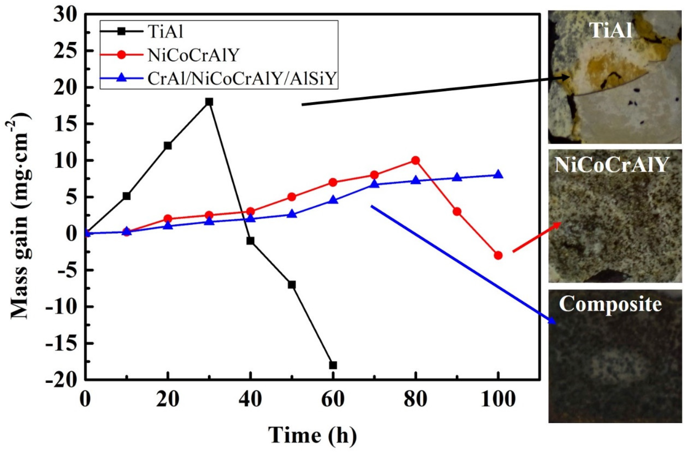
3.3.1. Corrosion Kinetic Curves

The TiAl substrate, NiCoCrAlY-coated and CrAl/NiCoCrAlY/AlSiY-coated samples were corroded in 75%NaCl + 25%Na2SO4 molten salt at 950 °C for 100 h; the corrosion kinetics curves are shown in Figure 4. The corrosion weight gains of the TiAl substrate, NiCoCrAlY coating, and CrAl/NiCoCrAlY/AlSiY composite coating were −18 mg·cm−2, −2.5 mg·cm−2, and 8 mg·cm−2, respectively. The TiAl alloy substrate began to exhibit obvious negative weight gain after 40 h of corrosion, and most of the surface oxide layer peeled off and was completely corroded at 60 h, at which point the test was stopped. After 80 h of hot corrosion, the NiCoCrAlY-coated sample experienced large area shedding on the surface, resulting in a negative corrosion weight gain; the coating was severely corroded. However, the CrAl/NiCoCrAlY/AlSiY composite coating maintained relatively stable growth, without the phenomenon of peeling weight loss. The macroscopic morphology also revealed that more than half of the TiAl substrate surface had shed, and parts of the NiCoCrAlY coating had fallen off at the corners. In contrast, the CrAl/NiCoCrAlY/AlSiY composite coating showed no significant shedding after 100 h of hot corrosion. All these results indicate that compared to other coatings on TiAl alloy substrates (Table 3) [21,22,23,24,25,26,27], the CrAl/NiCoCrAlY/AlSiY gradient composite coating demonstrates good hot corrosion resistance, even at 950 °C.

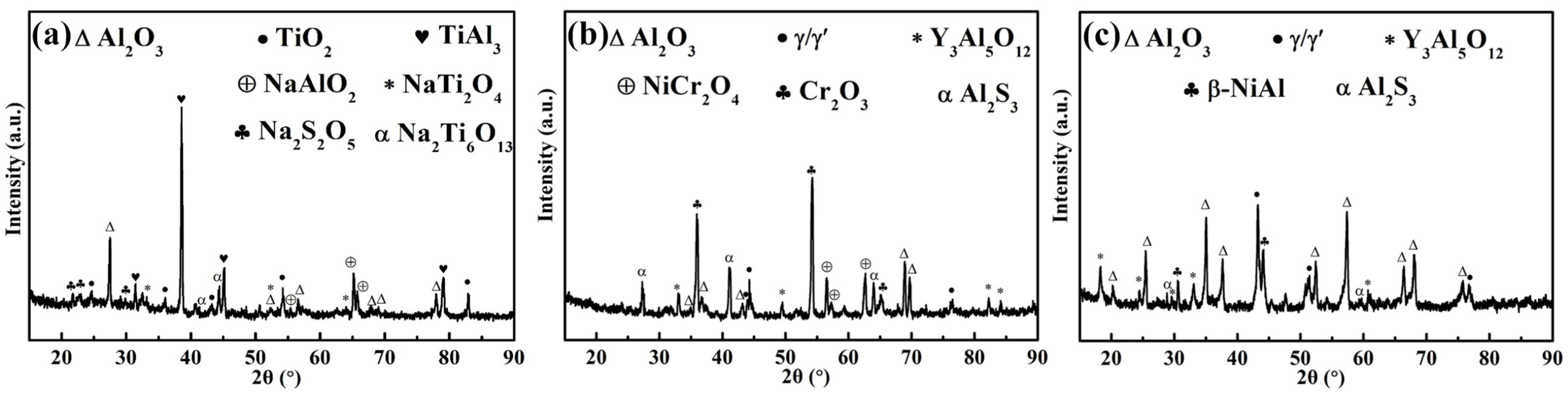
3.3.2. Structural Analysis

The surface oxides of the TiAl substrate were mainly TiO2 and Al2O3 after corrosion at high temperature for 60 h, as shown in the XRD pattern (Figure 5a). In addition, some heterogeneous phases with weak diffraction peaks were observed, such as NaAlO2, NaTi2O4, Na2S2O5, and Na2Ti6O13 corrosion products. Figure 5b shows the XRD pattern of the NiCoCrAlY coating after hot corrosion for 100 h. It can be seen that numerous corrosion products were generated on the coating surface and weak γ/γ’ phase diffraction peaks were retained. At this stage, the oxides were predominantly Cr2O3, Al2O3, and NiCr2O4. Moreover, small amounts of Y3Al5O12 and Al2S3 were also observed. For the CrAl/NiCoCrAlY/AlSiY composite coating after hot corrosion for 100 h (Figure 5c), the diffraction pattern of the corrosion product was still mainly Al2O3. This was accompanied by a small amount of the YAG (Y3Al5O12) phase. The Y-containing phase was dispersed in the Al2O3 to inhibit the propagation of microcracks in the oxide film. Simultaneously, a small amount of sulfide Al2S3 appeared, the content of γ/γ’ in the oxide film was higher, and the β-NiAl phase was reduced.

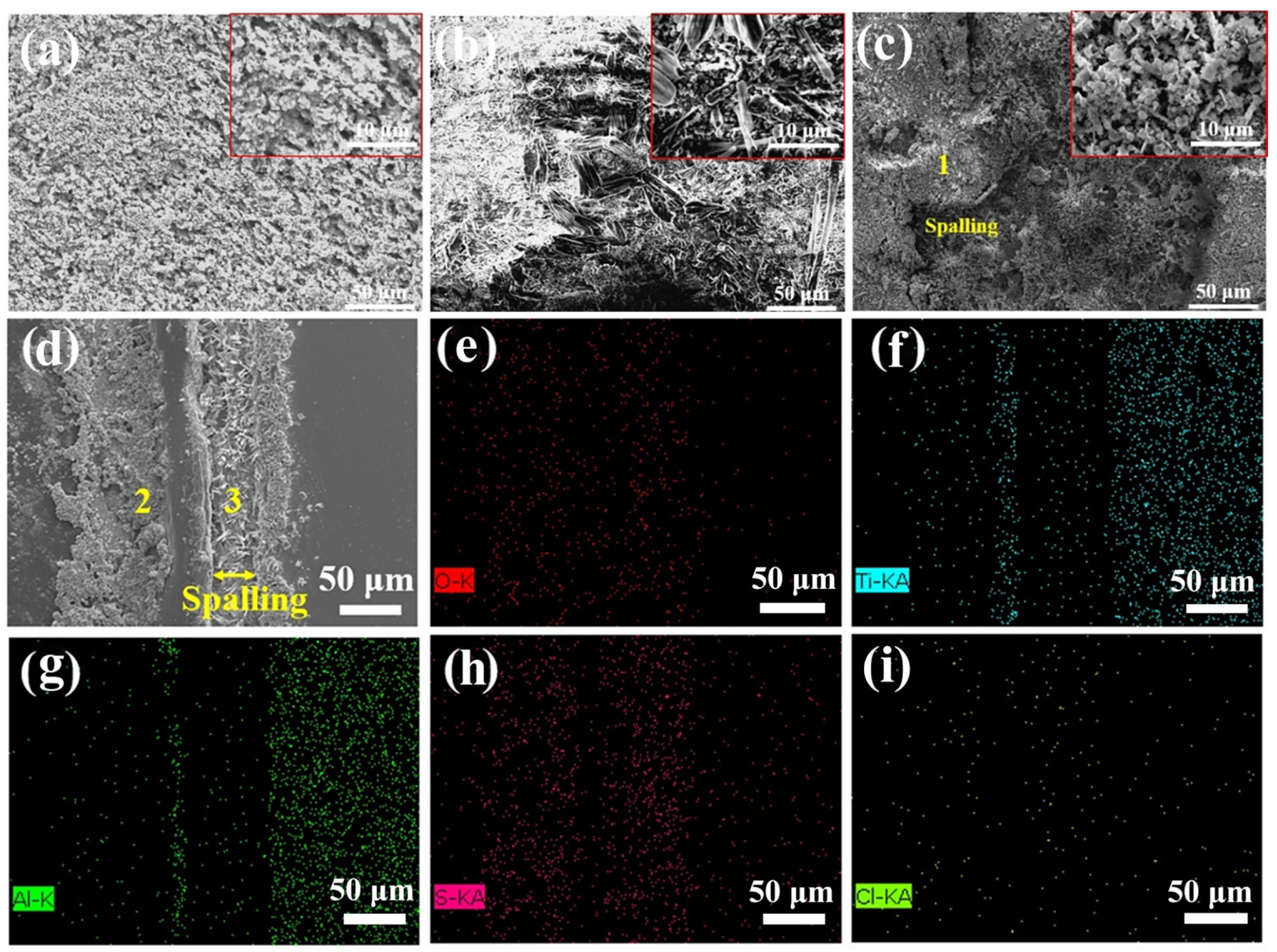
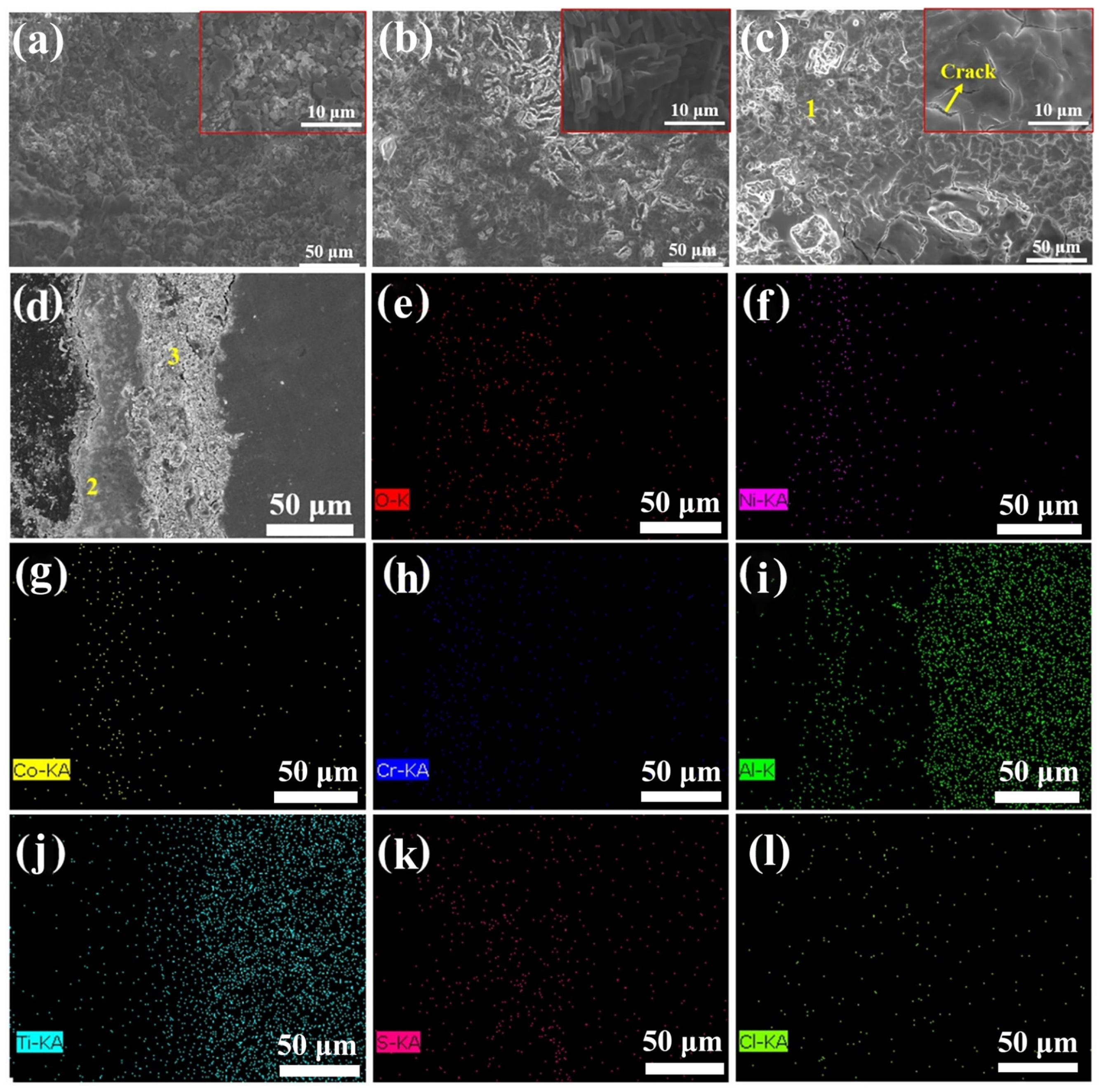
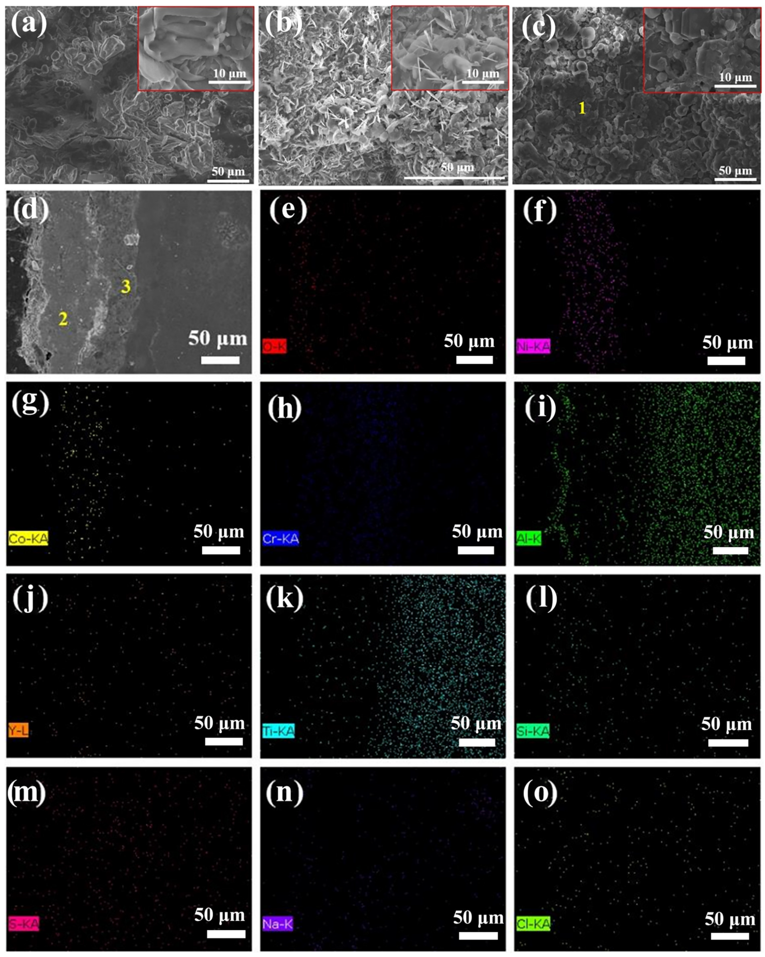
3.3.3. Morphology Analysis
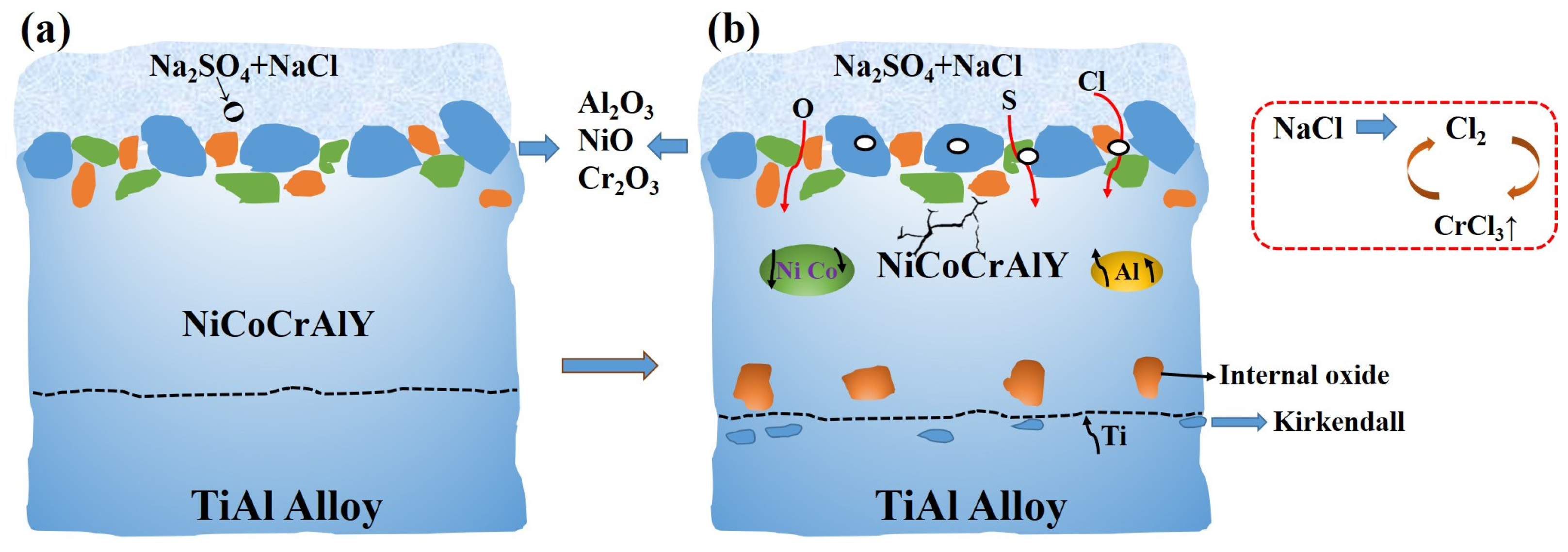
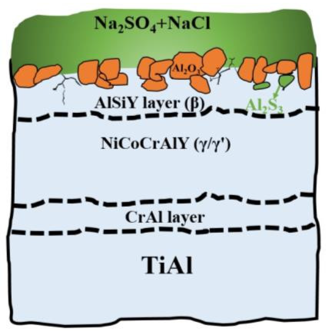
After 10 h of hot corrosion, the TiAl substrate began to exhibit a slight pore structure on the surface, along with a small amount of grain formation due to attached residual molten salt solidification, as shown in Figure 6a. When the hot corrosion time increased to 50 h (Figure 6b), more whisker-like structures appeared, generated by the rapid growth of unstable oxides such as θ-Al2O3, accompanied by large area cracks, indicating severe corrosion of the substrate at this time. When the hot corrosion time increased to 60 h, obvious local shedding occurred on the substrate surface (Figure 6c), signaling complete corrosion of the substrate and termination of the corrosion test. The local enlargement image in Figure 6c reveals that a relatively porous area was generated on the shed surface, attributed to the loose oxide structure precipitated after oxide melting. The non-shedding area 1 of the substrate surface after 60 h of corrosion was selected for EDS point scan analysis. The main components of this area were Al2O3 and TiO2, consistent with the XRD results. Figure 6d shows an SEM image of the cross-section and an element surface map of the TiAl substrate corroded for 60 h. The remaining corrosion products on the substrate were mainly the mixture of TiO2 and Al2O3 at about 100 μm with obvious cracking and delamination. According to the EDS surface scan results, S, Cl, Na, and O accumulated in large quantities in the interior of the peeling coating, causing severe internal oxidation and sulfidation. It was due to the rapid consumption of Al and Ti on the substrate surface, resulting in the formation of relatively loose oxides, which caused S2− and Cl to rapidly diffuse to the unoxidized TiAl surface. However, the α2 phase with a higher Ti content in the γ + α2 near-lamellar structure of the TiAl substrate was more prone to generating TiO2 quickly, and TiO2 was prone to acidic melting in a sustainable Na2SO4 environment [11], accelerating the corrosion process. EDS point scan results in area 2 of Table 4 show that the surface corrosion products were still TiO2 and Al2O3 mixtures, while in area 3, due to O2−, S2− and Cl penetrating through the loose corrosion products and contacting the internal substrate, the partial pressure of some elements in the area increased, resulting in internal oxidation and sulfidation. Na2SO4 and NaCl also accumulated in large quantities. The substrate also exhibited complete failure morphology.
Figure 7 shows the hot corrosion morphology of the NiCoCrAlY coating at different times. After 10 h of corrosion (Figure 7a), the NiCoCrAlY coating appeared relatively uniform and dense, with no obvious cracks, holes, and other defects. When the corrosion time increased to 50 h (Figure 7b), the surface of the NiCoCrAlY coating appeared uneven long strips of Cr2O3, and its density decreased relatively. At 100 h of corrosion, the NiCoCrAlY coating surface exhibited obvious cracks and loose oxidation products, with poor coating density (Figure 7c). EDS point scan analysis of area 1 in Table 5 also shows a high O content, indicating that the coating surface was mainly composed of elemental oxides mixed with sulfides. The cross-section morphology (Figure 7d) of the NiCoCrAlY coating after 100 h of hot corrosion testing and EDS surface scanning results (Figure 7e–l) were analyzed. The oxides of the coating were loose and full of gaps and holes, with obvious oxide spalling. Combined with the EDS results, it can be seen that S2− and O2− crossed discontinuous oxides into the interior of the coating, significantly accelerating the rate of hot corrosion and increasing the content of oxides and sulfides, consistent with the EDS point scan results of area 2 in Table 5. Due to the interdiffusion of elements between the coating and the substrate, brittle phases were generated, producing areas of stress concentration at high temperatures, eventually forming cracks between the coating and the substrate. In addition, the generation of Kirkendall holes and the mismatch in thermal expansion coefficients between the coating and substrate further compromised the binding performance. During the high-temperature corrosion process, elements such as S, Cl, and O crossed the loose oxide film and the coating, absorbing into the pores between TiAl/NiCoCrAlY. This rapidly led to internal oxidation and internal sulfidation, resulting in the accumulation of various oxides, sulfides, and salts, as shown in the EDS results of area 3 in Table 5. Although the coating did not completely peel off from the substrate, the oxide film was seriously damaged and the interior was loose, no longer providing protection to the substrate.
Figure 8 shows the hot corrosion morphology of the CrAl/NiCoCrAlY/AlSiY coating at different times. When the corrosion time was 10 h, many unevenly distributed granular particles appeared on the coating surface (Figure 8a). When the corrosion time increased to 50 h, the long strip particles became dense pinholes, caused by the rapid growth of the unstable Al2O3 structure, as shown in Figure 8b. When the corrosion time reached 100 h, the particle size on the coating surface increased, and the distribution became relatively uniform with a few holes, while no obvious cracks and peeling areas were observed (Figure 8c). According to the EDS point scan analysis results in area 1 in Table 6, the surface products were mainly Al2O3, and small amounts of Ni, Co, Cr, and other elements were detected. These results indicated that a protective oxide layer could still be formed on the surface of the CrAl/NiCoCrAlY/AlSiY composite coating. The cross-section of the coating was complete and dense, with no obvious peeling damage inside (Figure 8d). Although cracks and other defects appeared on the oxide surface of the coating, the coating with good binding still had a protective effect on the substrate. The EDS surface scanning results (Figure 8e–o) showed less sulfide production in the coating. The generation of sulfide was due to S entering the subsurface layer and forming compounds with Al, after crossing the Al2O3 channel with pores in the upper layer. Simultaneously, the NiCoCrAlY layer and CrAl layer showed slight porosity but did not expand widely. According to the EDS results of area 3 in Table 6, there was a small amount of O aggregation present. In summary, the protection of the composite coating on the substrate was weakened, and there was a slight interdiffusion phenomenon inside after hot corrosion. However, compared with the NiCoCrAlY coating, it still provided better protection for the TiAl substrate.

4. Discussion

The corrosion mechanisms of the TiAl substrate, NiCoCrAlY coating, and CrAl/NiCoCrAlY/AlSiY coating were analyzed in detail. During hot corrosion, the TiAl substrate initially oxidizes with oxygen. However, since the TiAl surface is coated with a 75%Na2SO4 + 25%NaCl salt film, oxygen from the external air has difficulty penetrating the salt solution to participate in the oxidation reaction, so most of the oxygen required for substrate oxidation comes from decomposition, as shown in the following equation:
Na2SO4 → Na2O + SO3
SO3 → 2S + 3O2
In the early stage of molten salt corrosion, Al2O3 forms first due to its relatively negative Gibbs free energy, and TiO2 grows faster and alternates with Al2O3. Although continuous Al2O3 is relatively stable in neutral salts, elements such as S have difficulty penetrating the inside and are not easily decomposed. However, melting will still occur in a long-term molten salt environment. Al2O3 is a strongly acidic oxide, which tends to melt in the salt film and combine with O2− to generate AlO2− anions through alkaline melting [28]. Conversely TiO2 is prone to acidic melting. The simultaneous occurrence of these two melting mechanisms influences and accelerates the other, forming a “collaborative corrosion”. This rapidly increases the degree of corrosion, resulting in the precipitation and formation of a loose oxidation mixture. The loose Al2O3 and TiO2 provide channels for S2− and O2− to diffuse into the TiAl substrate, leading to severe corrosion. As molten salt corrosion progresses, increasing amounts of O2− and S2− enter the substrate, and TiO2 reacts with Na2O, accelerating TiO2 consumption. This process can be represented by the following equation:
TiO2 + Na2O → Na2Ti6O13
The addition of NaCl accelerates the corrosion process. First of all, NaCl can react with O2 to form chlorine gas in molten salt at high temperatures, which readily reacts with Al to form AlCl3. The formation of AlCl3 consumes the Al content in the substrate, reducing the hot corrosion resistance of the TiAl alloy. Subsequently, Al and Cl2 continue to produce AlCl3, further accelerating the corrosion rate. In the γ + α2 lamellar structure of the TiAl substrate, the Ti content in the α2 area is higher, leading to a faster TiO2 growth rate. This results in preferential corrosion and oxidizes the α2 phase, forming loose oxides that provide channels for the diffusion of Cl and S. This process causes the substrate to crack. The brief failure process is illustrated in Figure 9.
For the corrosion of the NiCoCrAlY coating in a Na2SO4 + NaCl environment, oxygen is initially provided by Na2SO4. As shown in Figure 10, mixed oxides of Al2O3, NiO, and Cr2O3 are formed on the coating surface after the increase in O partial pressure, and these oxides are also prone to “collaborative melting” in Na2SO4. This occurs because Al and Cr in the coating tend to form acidic oxides, which are susceptible to alkaline dissolution. Compared to Cr and Al, Ni and Co tend to form alkaline oxides. Acid and base melting occur simultaneously, promoting and accelerating each other, which further accelerates the corrosion rate. After melting, these oxides precipitate again, resulting in a loose structure with no protective properties. Moreover, the mixture of NiO, NiCr2O4, and other spinel structures is loose and offers poor protection. The diffusion of O, S, and Cl elements accelerates into the interior of the coating, reacting with the unoxidized area, causing internal oxidation and sulfidation and further producing oxides and even sulfides with worse protective capabilities. The addition of NaCl exacerbates the corrosion caused by Na2SO4. Generally, the damage caused by Cl2 accelerates the oxidation and sulfidation of the coating until the salt film on the coating surface is completely consumed. Specifically, Na2SO4 has a high melting point (884 °C), but the melting point of its mixed salt after adding NaCl is below 700 °C, making Cl and S2− ions more mobile. In addition, NaCl produces AlCl3, CrCl3 (volatile chlorides), and Cl2 during hot corrosion. The formation of Cl2 quickly leads to holes and crack boundaries, providing channels for external elements such as O and S to corrode the internal components of the coating. Consequently, holes and pits form at the grain boundaries. The volatile CrCl3 diffuses outward to the outer surface through cracks and boundaries, while the chloride is re-oxidized into Cl2 simultaneously: 2CrCl3 + 3/2O2 → Cr2O3 + 3Cl2. The resulting chlorine gas re-enters the coating for further corrosion, continuing the cycle. Other elements in the coating undergo a similar corrosion process. It is evident that NaCl in molten salt acts as a catalyst to accelerate oxidation, and mixed salt causes more severe corrosion problems than pure Na2SO4 salt. During hot corrosion, Kirkendall holes are produced between the NiCoCrAlY coating and substrate. Once such defects form, oxygen rapidly diffuses into the specimen and accelerates the internal oxidation rate, leading to a coating failure.
For the CrAl/NiCoCrAlY/AlSiY gradient composite coating, a continuous dense Al2O3 layer forms on the surface during the initial oxidation stage due to the Al-rich outer layer. Although continuous Al2O3 is destroyed as the Al2O3 + O2− → 2AlO2− reaction progresses, the alkalinity in the solution is reduced, slowing down the reaction. In addition, the Al2O3 precipitated by melting remains relatively dense and provides some protection. When the Al content on the surface is sufficiently high, selective oxidation of Al continues, healing molten pores accordingly. This partially balances and compensates for the melting and consumption of the coating, improving its corrosion resistance. However, the surface Al content of monolayer NiCoCrAlY is low, so the rate of Al selective oxidation to the oxide film is lower than that of melting. Simultaneously, if the partial pressure of sulfur is high during hot corrosion, a large number of non-protective Al2S3 sulfides will form in the lower layer of Al2O3. In this experiment, no sulfide formation was found below 950 °C, and only a small amount of sulfide was observed at 950 °C, possibly influenced by Si and Y elements on the coating’s surface layer. Specifically, Si forms SiO2 during hot corrosion, enabling SiO2 to form a glass phase or silicates that can reduce sulfide with elements in the coating. Furthermore, the silicon-containing coating is relatively inert, inhibiting Al2S3 formation [29]. Moreover, the bias of Y2O3 at the grain boundary prevents some S2− from diffusing inward, and Y also reacts with S at the initial oxidation stage to reduce Al2S3 production. Figure 11 shows the mechanism of partial coating degradation of the composite coating resistant to molten salt corrosion at 950 °C.
As the corrosion continues, the Cr-rich layer inside the coating may be exposed, and the melting process of Cr2O3 requires O2 participation, as shown in Formula 4:
2Cr2O3 + 2O2− + 3O2 → 2Cr2O72−
Therefore, the solubility of Cr2O3 is generally higher at the air/molten salt interface than at the molten salt/oxide film interface, resulting in a discontinuation of the corrosion process and the maintenance of good corrosion resistance [30]. In this test, no large-scale peeling phenomenon was observed in the upper layer of the coating, and the Cr-rich layer did not participate directly in reactions with the molten salt. Instead, this layer was more involved in preventing the interdiffusion of elements. Overall, the CrAl/NiCoCrAlY/AlSiY gradient composite coating effectively improves the resistance of NiCoCrAlY to molten salt corrosion.

5. Conclusions

From the above experimental results, the following conclusions can be drawn:
(1)
The prepared CrAl/NiCoCrAlY/AlSiY gradient composite coating is dense with 10 [9.06, 10.94] μm, 45 [42.49, 47.51] μm, and 5 [4.52, 5.48] μm for the CrAl layer, NiCoCrAlY layer, and AlSiY layer, respectively. The elements in the composite coating show a gradient distribution.
(2)
After corrosion at 950 °C, the TiAl substrate and NiCoCrAlY coating exhibit obvious corrosion loss, while the composite coating shows no weight loss and remains stable.
(3)
Corrosion tests reveal that the TiAl substrate spalled largely and corroded completely. The NiCoCrAlY-coated sample also showed peeling phenomena. No obvious cracks occurred in the composite coating, demonstrating better hot corrosion resistance.
(4)
The main hot corrosion products of the TiAl substrate are TiO2 and Al2O3, with the loose porous TiO2 on the surface rendering the substrate completely ineffective. The NiCoCrAlY coating mainly produces uneven Cr2O3 and a variety of loose mixtures. The corrosion product of the composite coating is continuous Al2O3, which provides good hot corrosion resistance and effective protection for the substrate.
(5)
In subsequent studies, researchers could focus on improving the mechanical properties of the coating while enhancing its hot corrosion resistance. The coefficients of thermal expansion between layers of the composite coating also need to be considered when applying these coatings to high-temperature components of engines.

Author Contributions

Conceptualization, Y.S. and Q.M.; methodology, Y.S.; software, Y.S.; validation, W.L., S.S. and Z.D.; formal analysis, Q.M.; investigation, J.X.; resources, J.N.; data curation, J.G.; writing—original draft preparation, Y.S.; writing—review and editing, Q.M.; visualization, F.J.; supervision, W.L.; project administration, Q.M.; funding acquisition, Q.M. All authors have read and agreed to the published version of the manuscript.

Funding

This work was supported by the National Major Science and Technology Projects of China (Y2022-III-0004-0013) and the National Natural Science foundation of China (Grant No 52272065).

Institutional Review Board Statement

Not applicable.

Informed Consent Statement

Not applicable.

Data Availability Statement

Data are contained within the article.

Acknowledgments

The authors acknowledge the facilities in the Center for Microscopy and Analysis at Nanjing University of Aeronautics and Astronautics.

Conflicts of Interest

The authors declare no conflicts of interest.

References

  1. Tetsui, T. Identifying low-cost, machinable, impact-resistant TiAl alloys suitable for last-stage turbine blades of jet engines. Intermetallics 2024, 168, 108263. [Google Scholar] [CrossRef]
  2. Gao, Z.; Hu, R.; Zou, H.; Zhou, M.; Luo, X. Insight into the Ta alloying effects on the oxidation behavior and mechanism of cast TiAl alloy. Mater. Design 2024, 241, 112941. [Google Scholar] [CrossRef]
  3. Yang, Y.L.; Chen, Y.J.; Gesang, Y.; Pan, M.H.; Liang, Y. Tribological Properties of γ-TiAl Alloy Fretting against Nickel-Based Superalloy at Elevated Temperature. Tribol. Trans. 2024, 67, 259–269. [Google Scholar] [CrossRef]
  4. Swadźba, R.; Swadźba, L.; Mendala, B.; Bauer, P.P.; Laska, N.; Schulz, U. Microstructure and cyclic oxidation resistance of Si-aluminide coatings on γ-TiAl at 850 °C. Surf. Coat. Technol. 2020, 403, 126361. [Google Scholar] [CrossRef]
  5. Garip, Y. Investigation of isothermal oxidation performance of TiAl alloys sintered by different processing methods. Intermetallics 2020, 127, 106985. [Google Scholar] [CrossRef]
  6. Dai, J.; Sun, C.; Wang, A.; Zhang, H.; Li, S.; Zhang, H. High temperature oxidation and hot corrosion behaviors of Ti2AlNb alloy at 923 K and 1023 K. Corros. Sci. 2021, 184, 109336. [Google Scholar] [CrossRef]
  7. Kosieniak, E.; Biesiada, K.; Kaczorowski, J.; Innocenti, M. Corrosion failures in gas turbine hot components. J. Fail. Anal. Prev. 2013, 12, 330–337. [Google Scholar] [CrossRef]
  8. Zhang, Y.; Jiang, H.; Zhang, S.; Yang, Z.; Zhang, T.; Tian, S. Hot salt corrosion behavior of the Ti-44Al-4Nb-1.5Mo-(B,Y) alloy in the temperature range of 750-950 °C. J. Mater. Res. Technol. 2023, 26, 4887–4901. [Google Scholar] [CrossRef]
  9. Zhang, K.; Zhang, T.B.; Zhang, X.H.; Song, L. Corrosion resistance and interfacial morphologies of a high Nb-containing TiAl alloy with and without thermal barrier coatings in molten salts. Corrosion Sci. 2019, 156, 139–146. [Google Scholar] [CrossRef]
  10. Yao, Z.; Marek, M. NaCl-induced hot corrosion of a titanium aluminide alloy. Mat. Sci. Eng. A-Struct. 1995, 192, 994–1000. [Google Scholar] [CrossRef]
  11. Zhao, W.Y.; Xu, B.W.; Ma, Y.; Gong, S.K. Inter-phase selective corrosion of γ-TiAl alloy in molten salt environment at high temperature. Prog. Nat. Sci. 2011, 21, 322–329. [Google Scholar] [CrossRef]
  12. Gong, X.; Chen, R.R.; Wang, Y.; Su, Y.Q.; Guo, J.J.; Fu, H.Z. Microstructure and Oxidation Behavior of NiCoCrAlY Coating with Different Sm2O3 Concentration on TiAl Alloy. Front. Mater. 2021, 8, 710431. [Google Scholar] [CrossRef]
  13. Tian, S.W.; Zhang, Y.F.; Liu, J.H.; Zeng, S.W.; Jiang, H.T. Interdiffusion mechanism at the interface between TiAl alloy and NiCoCrAlY bond coating. Surf. Coat. Technol. 2022, 444, 128687. [Google Scholar] [CrossRef]
  14. Han, D.J.; Liu, D.D.; Niu, Y.R.; Qi, Z.X.; Pan, Y.Y.; Xu, H.; Zheng, X.B.; Chen, G. Interface stability of NiCrAlY coating without and with a Cr or Mo diffusion barrier on Ti-42Al-5Mn alloy. Corros. Sci. 2021, 188, 109538. [Google Scholar] [CrossRef]
  15. Xue, G.; Wang, Z.; Xiang, L.; Xiao, H.; Zhao, Y.; Wan, Y.; Ning, H.; Xie, Z. Enhancing hot corrosion performance of NiCoCrAlY/AlSiY coating by arc enhanced glow discharge. Mater. Lett. X 2022, 13, 100130. [Google Scholar] [CrossRef]
  16. Li, S.M.; Fu, L.B.; Zhang, W.L.; Li, W.; Sun, J.; Wang, T.G.; Jiang, S.M.; Gong, J.; Sun, C. Formation process and oxidation behavior of MCrAlY + AlSiY composite coatings on a Ni-based superalloy. J. Mate. Sci. Technol. 2022, 120, 65–77. [Google Scholar] [CrossRef]
  17. Xue, G.M.; Wang, Z.G.; Wang, E.L.; Tang, Y.; Zhao, Y.H.; Wang, Y.H.; Hu, S.Y.; Xiang, L.; Xie, Z.W. Enhanced Hot Salt-Water Corrosion Resistance of NiCoCrAlY-AlSiY Coating by Ion-Beam-Assisted Deposition. Coatings 2021, 11, 1062. [Google Scholar] [CrossRef]
  18. Zeng, S.; Li, J.; Chen, C.; Meng, Y.; Zhu, C.W.; Bao, Y.W.; Han, X.C.; Zhang, H.B. Oxidation behavior of CrAl coating with and without Nb addition in high temperature steam environment. J. Nucl. Mater. 2023, 581, 154437. [Google Scholar] [CrossRef]
  19. Xu, M.; Li, S.; Dong, Z.; Liu, H.; Wang, J.; Bao, Z.; Zhu, S.; Wange, F.H. High temperature performance and interface evolution of a NiCoCrAlY coating with Pt modification and Re-based diffusion barrier. Surf. Coat. Technol. 2023, 463, 129510. [Google Scholar] [CrossRef]
  20. Du, Y.; Clavaguera, N. Thermodynamic assessment of the Al-Ni system. J. Alloys Compd. 1996, 237, 20–32. [Google Scholar] [CrossRef]
  21. Li, Y.; Hao, Q.; Liang, G.; Liu, G.; Liu, S. Microstructure and hot corrosion properties of an Al-Y coating on TiAl alloy. J. Cent. South Univ. 2024, 31, 330–345. [Google Scholar] [CrossRef]
  22. Wang, D.; Xiao, R.; Qu, G.; Zhou, X. Influences of Laser Remelting on Hot Corrosion Resistance of Plasma-sprayed Nanostructured Al2O3-13wt.%TiO2 Coating. J. Phys. Conf. Ser. 2021, 1965, 012084. [Google Scholar] [CrossRef]
  23. Wei, Z.; Li, X.; Lv, W.; Ming, B.; Li, Y.; Liu, X.; Lai, S.; Liu, F. Structure and Hot Corrosion Behavior of an Al-Co-Y Co-deposited Coating on TiAl Alloy. J. Mat. Eng. Perf. 2023, 32, 4796–4806. [Google Scholar] [CrossRef]
  24. Li, Y.; Xie, F.; Yang, S. Microstructure and hot corrosion resistance of Si-Al-Y coated TiAl alloy. J. Cent. South Univ. 2020, 27, 2530–2537. [Google Scholar] [CrossRef]
  25. Liao, Y.; Feng, M.; Chen, M.; Geng, Z.; Liu, Y.; Wang, F.; Zhu, S. Comparative study of hot corrosion behavior of the enamel based composite coatings and the arc ion plating NiCrAlY on TiAl alloy. Acta Metall. Sin. 2019, 55, 229–237. [Google Scholar]
  26. Wang, D.; Tian, Z.; Shen, L.; Huang, Y. Hot corrosion resistance of plasma-sprayed MCrAlY coatings by laser remelting on TiAl alloy surface TiAl. Trans. China Weld. Inst. 2014, 35, 17–20. [Google Scholar]
  27. Tian, Z.J.; Gao, X.S.; Huang, Y.H.; Liu, Z.D.; Shen, L.D.; Wang, D.S. Study on Hot Corrosion Behavior of Plasma-Sprayed NiCoCrAl-Y2O3 Coating on TiAl Alloy Surface. Rare Met. Mater. Eng. 2010, 39, 1439–1442. [Google Scholar]
  28. Rapp, R.A. Hot corrosion of materials: A fluxing mechanism? Corros. Sci. 2002, 44, 209–221. [Google Scholar] [CrossRef]
  29. Guo, M.H.; Wang, Q.M.; Ke, P.L.; Gong, J.; Sun, C.; Huang, R.F.; Wen, L.S. The preparation and hot corrosion resistance of gradient NiCoCrAlYSiB coatings. Surf. Coat. Technol. 2006, 200, 3942–3949. [Google Scholar] [CrossRef]
  30. Xu, Y.; Miao, Q.; Wang, L.; Yu, X.; Jiang, Q.; Ren, B. Oxidation behavior of γ-TiAl alloy with NiCrAlY/Al duplex coating at 950 °C. Rare Met. Mat. Eng. 2014, 43, 1407–1411. [Google Scholar]
Figure 1. A schematic diagram of CrAl/NiCoCrAlY/AlSiY gradient composite coating preparation process.
Coatings 14 01067 g001
Figure 2. XRD patterns of (a) CrAl layer, (b) NiCoCrAlY layer, and (c) CrAl/NiCoCrAlY/AlSiY gradient composite coating.
Coatings 14 01067 g002
Figure 3. The surface morphologies of (a) CrAl layer, (c) NiCoCrAlY layer (e) AlSiY layer and their corresponding annealed morphologies and enlarged images (b,d,f). The cross-section morphology of (g) CrAl/NiCoCrAlY/AlSiY gradient composite coating and its EDS line scan spectrum (h).
Coatings 14 01067 g003
Figure 4. Hot corrosion kinetics curves of the TiAl substrate, NiCoCrAlY coating and the gradient composite coating and their corresponding surface morphologies.
Coatings 14 01067 g004
Figure 5. The XRD patterns of (a) TiAl substrate, (b) NiCoCrAlY coating and (c) the gradient composite coating after corrosion at 950 °C.
Coatings 14 01067 g005
Figure 6. The hot corrosion surface morphologies of TiAl substrate (a) 10 h, (b) 50 h (c) 60 h. (d) The cross-section morphology of TiAl substrate after corroded 60 h and its EDS line scan spectrums (ei).
Coatings 14 01067 g006
Figure 7. The hot corrosion surface morphologies of NiCoCrAlY coating (a) 10 h, (b) 50 h (c) 100 h. (d) The cross-section morphology of NiCoCrAlY coating after corroded 100 h and its EDS line scan spectrums (el).
Coatings 14 01067 g007
Figure 8. The hot corrosion surface morphologies of CrAl/NiCoCrAlY/AlSiY composite coating (a) 10 h, (b) 50 h (c) 100 h. (d) The cross-section morphology of CrAl/NiCoCrAlY/AlSiY composite coating after corroded 100 h and its EDS line scan spectrums (eo).
Coatings 14 01067 g008
Figure 9. The schematic diagrams of hot corrosion mechanism of TiAl substrate: (a) early stage, (b) intermediate stage and (c) late stage.
Coatings 14 01067 g009
Figure 10. The schematic diagrams of hot corrosion mechanism of NiCoCrAlY coating: (a) early stage, (b) late stage.
Coatings 14 01067 g010
Figure 11. The schematic diagrams of hot corrosion and failure mechanism of CrAl/NiCoCrAlY/AlSiY composite coating.
Coatings 14 01067 g011
Table 1. The specific process parameters of CrAl layer, NiCoCrAlY layer, AlSiY layer.
ParametersCrAl LayerNiCoCrAlY LayerAlSiY Layer
Oxygen pressure/MPa1.42--
Argon flow rate/sccm5.37 × 107-30
Working pressure/Pa1.24-1
Fuel flow/sccm2.12 × 105--
Carrier flow/sccm7.07 × 105--
Electricity/A-600-
Voltage/V-40-
Main gas (Ar)/MPa-0.5-
Auxiliary gas (He)/MPa-0.8-
Carrier gas (Ar)/MPa-0.3-
Powder feed rate/r·min−1-3-
Spraying distance/mm-100-
Spray gun moving speed/mm·s−1-80-
Distance (target − workpiece)/mm--15
Sputtering time/h--3
Table 2. The EDS point scan results of CrAl/NiCoCrAlY/AlSiY gradient composite coating at different areas (at.%).
AreasNiCoCrAlYOTi
128.21.22.265.50.32.6--
236.412.47.640.41.11.11.0
347.511.99.225.52.03.20.7
421.16.337.823.82.62.46.0
50.50.31.441.51.51.153.8
Table 3. Common hot-corrosion-resistant coatings on TiAl substrate.
CoatingSubstrate
(at.%)
Preparation TechnologyMolten Salt Composition
(wt.%)
ExposureMax. Mass Gain
(mg/cm2)
Al-basedAl-YTi−48Al−2Nb−2CrPack cementation process75% Na2SO4 + 25% NaCl850 °C, 35 h−2 [21]
Al2O3-TiO2Ti−46.5Al−2.5V−1CrPlasma spraying75% Na2SO4 + 25% NaCl850 °C, 50 h5.5 [22]
Al-Co-YTi−45Al−8Nb−0.1YPack cementation process75% K2SO4 + 25% NaCl850 °C, 25 h30.66 [23]
Si-Al-YTi−48Al−2Cr−2NbPack cementation process75% Na2SO4 + 25% K2SO4900 °C, 20 h6.01 [24]
MCrAlYNiCrAlYTi−45Al−2Mn−2NbMulti arc ion plating75% Na2SO4 + 25% NaCl850 °C, 160 h5.456 [25]
NiCoCrAlYTi−46.5Al−2.5V−1CrPlasma spraying75% Na2SO4 + 25% NaCl850 °C, 40 h5 [26]
CompositeNiCoCrAl-Y2O3Ti−46.5Al−2.5V−1CrPlasma spraying75% Na2SO4 + 25% NaCl850 °C, 20 h4 [27]
CrAl/NiCoCrAlY/AlSiYTi−46.5Al−1Cr−0.6VVarious75% Na2SO4 + 25% NaCl950 °C, 100 h8 (This work)
Table 4. The EDS point scan results of corroded TiAl substrate at different areas (at.%).
PointsOTiAlSClNa
162.621.414.30.90.20.6
262.021.215.30.70.30.5
352.315.710.56.77.27.6
Table 5. The EDS point scan results of corroded NiCoCrAlY coating at different areas (at.%).
AreasONiAlCrCoYTiSClNa
152.121.510.74.83.71.3--3.00.42.5
218.639.318.97.36.71.7--5.30.31.9
341.312.715.95.72.30.311.29.50.11.0
Table 6. The EDS point scan results of corroded CrAl/NiCoCrAlY/AlSiY composite coating at different areas (at.%).
AreasONiAlCrCoYTiSiSClNa
150.77.831.72.81.20.6--1.23.10.80.1
23.653.321.410.97.91.2----0.5--1.2
34.62.823.731.83.40.132.7--0.9----
Disclaimer/Publisher’s Note: The statements, opinions and data contained in all publications are solely those of the individual author(s) and contributor(s) and not of MDPI and/or the editor(s). MDPI and/or the editor(s) disclaim responsibility for any injury to people or property resulting from any ideas, methods, instructions or products referred to in the content.

