Article

Microstructures and Properties of Laser-Cladded FeCoCrNiAlTi High-Entropy Alloy with Intensive Repair Potential

1
Shenyang National Laboratory for Materials Science, Institute of Metal Research, CAS, Shenyang 110016, China
2
School of Materials Science and Engineering, Changchun University of Science and Technology, Changchun 130022, China
3
National Key Laboratory for Remanufacturing, Beijing 100072, China
*
Authors to whom correspondence should be addressed.
Coatings 2024, 14(8), 1068; https://doi.org/10.3390/coatings14081068 (registering DOI)
Submission received: 2 July 2024 / Revised: 18 July 2024 / Accepted: 19 July 2024 / Published: 21 August 2024
(This article belongs to the Special Issue Research and Application of High Entropy Alloys)

Abstract

:
As a key step in intensive additive repair, the design of intensive repair materials immediately needs to be explored. In this work, an intensive additive repair study based on laser cladding technology was performed using a self-designed Fe20Co25Ni31Cr8Al9Ti7 high-entropy alloy (HEA) powder and three types of substrates widely used in field equipment (namely, Q235, 17CrNiMo6H, and 304 stainless steel). The results revealed that the HEA repair layer (HEA-RL) consists of a dominant FCC phase and a small amount of BCC phase, and the microstructure shows the columnar-to-equiaxed grain transition behavior. The metallurgical bonding between the HEA-RL and the three substrates has almost no defects. Compared with the three substrates, the HEA-RL has a much higher microhardness (~340 HV) and decent corrosion resistance. Therefore, the underlying mechanisms for the microstructure and performance of the HEA-RL were also discussed. This work provides a new idea for the design of intensive repair materials.

1. Introduction

The rapid emergency maintenance of damaged parts is of great significance for ensuring the long-term operation of field equipment. Compared to traditional repair methods, laser cladding (LC) has high flexibility, high bonding strength, and fast speed, making it favored in the emergency maintenance of field equipment [1]. However, field equipment is usually composed of abundant parts with different materials, and the damage is sudden and random. Considering the flexibility and timeliness of emergency maintenance, it is almost impossible for the LC repair system to carry a large amount of each repair material in a wild environment. In response to the problem, the concept of intensive additive repair came into being, i.e., using a small amount of broad-spectrum high-performance materials to repair various substrates [2]. Consequently, the exploration of intensive repair materials is becoming a research hotspot in this field.
As a new class of metal materials emerging in recent years, high-entropy alloys (HEAs) have gained much attention due to their wide component design space and attractive properties. Different from the design approach based on a single principal element in traditional alloys [3], HEAs are composed of five or more principal elements in the content ranging from 5% to 35at.%, which gives them four unique core effects: high entropy effect, sluggish diffusion effect, lattice distortion effect, and cocktail effect. Notably, HEAs tend to form simple solid-solution phases rather than intermetallic compounds, such as the single face-centered cubic (FCC)/body-centered cubic (BCC)/hexagonal close-packed (HCP) phase, or their mixed phases, due to the fact that a sufficiently high configurational entropy can overcome the effect of the enthalpy of compound formation [4]. It is worth noting that among numerous reported HEAs, FeCoNiCr HEA and its derivatives hold synergistic solid-solution, fine-grain, precipitation, and diffusion-strengthening mechanisms, thus showing high strength, hardness, and corrosion resistance [5,6]. Accordingly, this system HEAs hold potential application prospects in the field of laser additive repair. For example, Su et al. [7] successfully repaired tungsten heavy alloy die-casting molds by using LC to prepare the CoCrFeNiW HEA coating on damaged surfaces and found that CoCrFeNiW0.8 HEA coating has good tempering stability. Qiu et al. [8] prepared CoCrFeNiMo HEA coating on the surface of 45 steel. The results revealed that the maximum hardness of the coating can reach 741 HV resulting from ultrafine microstructures; in this case, the wear resistance is improved. More importantly, from the perspective of the element compatibility between the repair material and the substrate [7], this kind of HEAs may be an ideal intensive repair material, since its elemental composition (such as Fe, Cr, and Ni) can be frequently found in traditional alloys. Unfortunately, relevant studies have not been reported.
With the above outlook in mind, based on our previous work [5], an ameliorated Fe20Co25Ni31Cr8Al9Ti7 HEA powder (by reducing Cr and increasing Ni and Al content to suppress the formation of the brittle Cr-rich phase) was chosen to repair three substrates widely used in field equipment (namely, Q235, 17CrNiMo6H, and 304 stainless steel (304SS)) [9,10] to explore the potential of HEAs for intensive repair. Because these substrates in the service environment tend to undergo damage or corrosion, the microhardness and corrosion resistance of the HEA repair layer (HEA-RL) were studied. The current study is expected to broaden the application field of HEA and provide a reference for the design of intensive restoration materials.

2. Experimental Section

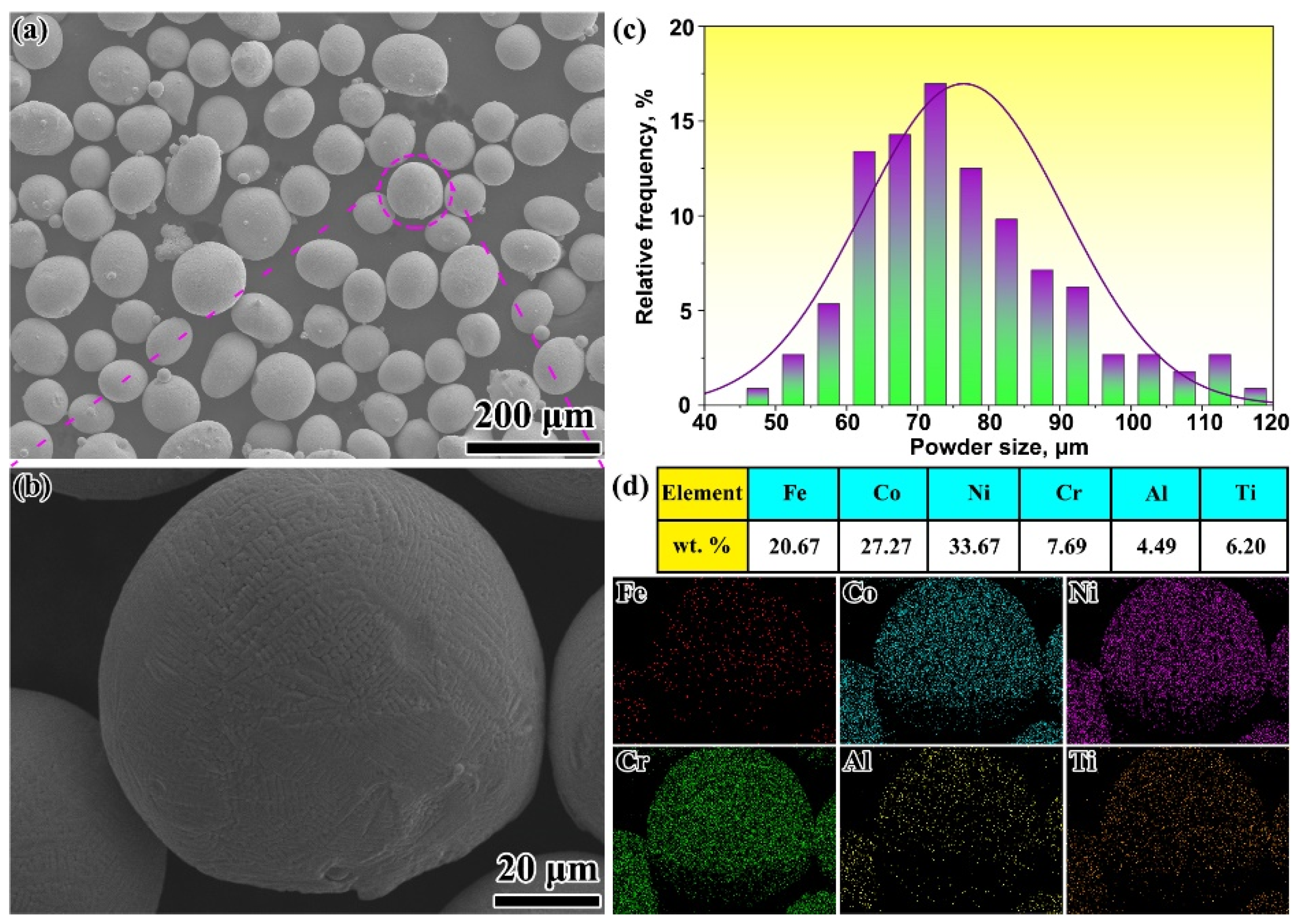
In this work, a self-designed HEA powder, which is spherical or ellipsoidal with a particle size distributed between 47 and 118 μm, was prepared by vacuum melting and high-pressure atomization. Specifically, in the preparation, the HEA ingot with a nominal composition of Fe20Co25Ni31Cr8Al9Ti7 (at.%) was first prepared by vacuum-melting a mixture of pure metals (>99.95%, wt.%). These pure metals were provided by Boyu Metal Co., Ltd., Shenyang, China. To ensure the uniformity of element distribution, the HEA ingot was repeatedly melted 3 times. Then the ingot was re-melted at 1500 °C in an induction crucible, and the melted liquid metal was delivered to the tip of the atomization nozzle through a melt pour tube with 3 mm in internal diameter and was subsequently split into small droplets by high-pressure (about 5 MPa) Ar gas stream. The chemical composition of the finally prepared HEA powder in wt.% is 20.67 Fe, 27.27 Co, 33.67 Ni, 7.69 Cr, 4.49 Al, and 6.20 Ti (Figure 1). Additionally, the chemical compositions of the three substrates utilized in the test are also given in Table 1. Prior to the deposition, the surfaces of these substrates were mechanically polished with 200# and 400# sandpapers to remove any oxides and oil stains, followed by cleaning with acetone solution and drying. To obtain HEA-RL, a YDFL-6000-CW-MM fiber laser was used. The repair process was implemented in a high-purity Ar environment. Based on a systematic orthogonal exploration of the LC process, the optimal process parameters were as follows: a laser power of 600 W, a scanning speed of 120 mm/s, a feed rate of 0.5 mg/min, and an overlap rate of 50%.
The crystal structure of the HEA-RL was characterized by X-ray diffraction (XRD, Bruker D8, Bruker-AXS Company, Karlsruhe, Germany) with Cu-Kα radiation and scanning in the range of 20°~100°. The microstructures and the chemical compositions of the HEA-RL were identified by using scanning electron microscopy (SEM, ZEISS SUPRA55, Carl Zeiss Co., Ltd, Oberkochen, Germany) equipped with energy-dispersive spectroscopy (EDS) and electron backscatter diffraction (EBSD) system. Note that the EBSD data were analyzed using the commercially available HKL Channel 5 software (Version 2007). The microhardness was determined using a Q10A+ Vickers hardness tester (Qness GmbH Company, Salzburg, Austria) at room temperature using a 100 g load for 15 s, starting from the HEA-RL near the repair interface and moving down to the substrate.
The corrosion performance of the samples was evaluated via the electrochemical tests in a 3.5 wt.% NaCl solution using a Reference600+ GAMRY electrochemical workstation (Gamry Instruments, Warminster, PA, USA) with a standard three-electrode electrochemical cell. Before testing, the samples were sequentially polished using 400 to 2000-grit SiC abrasive papers and then rinsed with deionized water. To ensure that the work electrode reached a relatively stable state during the tests, open-circuit potential tests were performed for 1 h. Then the electrochemical impedance spectroscopy (EIS) tests with a frequency from 100 kHz to 10 mHz and a sinusoidal amplitude of 10 mV were conducted. Finally, the potentiodynamic polarization (PDP) test was positively scanned with a sweep speed of 0.5 mV s−1. The potentiostatic polarization (PSP) tests for 304SS and the HEA layer were performed at 0 VSCE. Mott–Schottky test was conducted from 0.4 VSCE to −0.3 VSCE with a potential scan with a rate of 20 mV s−1. Furthermore, the corrosion morphologies of the HEA-RL and the substrates were also observed by SEM.

3. Results and Discussion

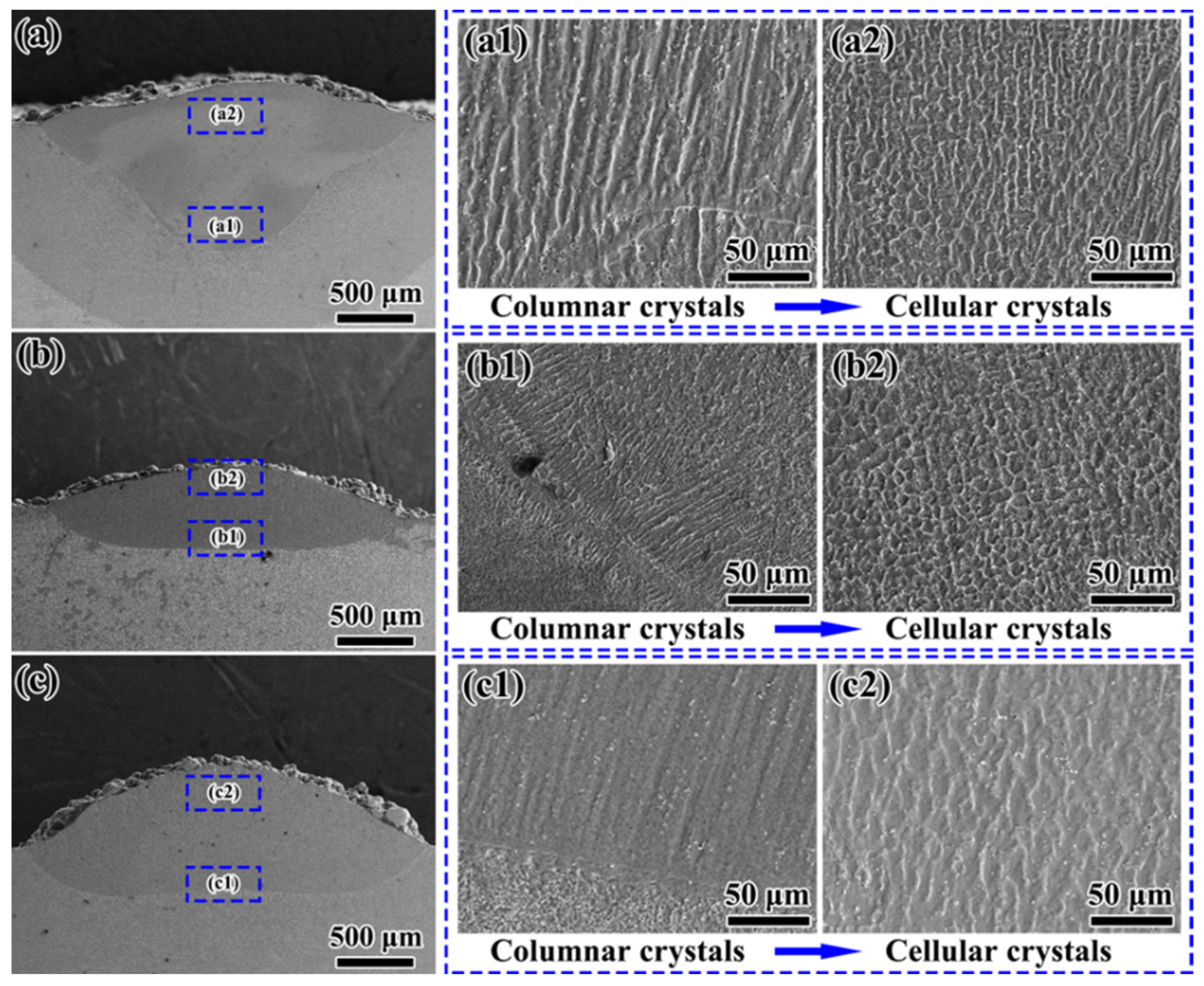
Figure 2a–c shows SEM images of the cross-sections of the HEA-RL obtained by single-layer single-pass cladding for three types of substrates. Clearly, regardless of the substrate, a good metallurgical bond can be formed between the substrate and the HEA-RL, and no obvious defects are found in the HEA-RL (Figure 2a–c), indicating the rationality of the currently selected process parameters. High-magnification observations reveal that the bottom of the HEA-RL is dominated by columnar crystals (Figure 2(a1,b1,c1)), while the top regions show obvious equiaxed crystal features (Figure 2(a2,b2,c2)). Such a columnar-to-equiaxed transition behavior has also been reported in other studies [11,12]. As pointed out by Kurz et al. [13], the occurrence of this transformation is closely related to two important solidification parameters: temperature gradient G and solidification rate R. The molten pool formed by the LC is usually semicircular, and its heat dissipation direction is from the bottom of the molten pool to the top. The bottom and top areas of the melt pool have the highest G and R, respectively [14]. A high G provides the driving force for the growth of columnar crystals along the gradient direction [15]. With increasing deposition height, the heat accumulation at the top of the melt pool increases, leading to a decrease in the G/R value, which corresponds to an increase in the degree of constitutional undercooling [16]. Consequently, the growth of crystals with the preferred orientation will be inhibited, thus promoting the formation of equiaxed crystals.
Furthermore, six-layer multi-pass cladding tests are also carried out, and the cross-section morphologies of the HEA-RL are shown in Figure 3a–c. It can be seen that only a small number of small-sized pores appear on the cross-sections of the cladding layers. Meanwhile, EDS mapping (Figure 3d–f) reveals that the overall distribution of the elements in the HEA-RL is relatively uniform. Benefiting from the sluggish diffusion effect of HEA [3], the spread of the elements in the additive prosthesis to the substrate is limited.
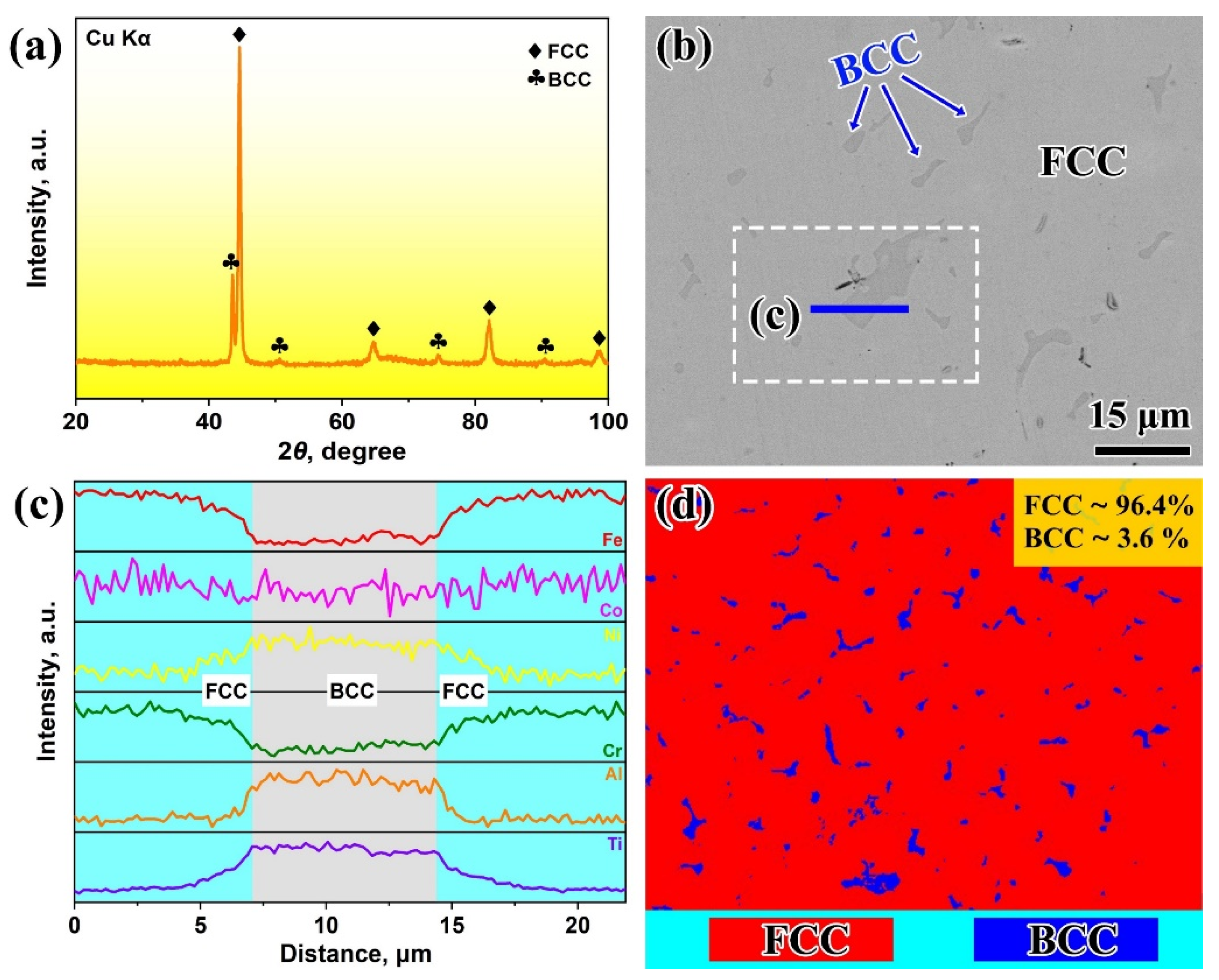
Taking the 304SS substrate as an example, Figure 4a shows the XRD pattern of HEA-RL. As seen, the HEA-RL mainly consists of an FCC phase (pdf#14–6032) and a BCC phase (pdf#23–8047). This is also supported by the SEM observations. As shown in Figure 4b, the HEA-RL exhibits a typical dual-phase structure, where the dark irregular phases are embedded into the bright matrix. The EDS line scanning results indicate that the dark-contrast phase is enriched with Ni, Ti, and Al, whereas Fe and Cr are enriched in the bright-contrast matrix (Figure 4c). Co displays a nearly uniform distribution, although a weak partitioning towards the latter is still visible. According to reference [17], the matrix and dark-contrast phase were defined as FCC and BCC phases, respectively. To quantitatively evaluate the phase composition in the alloy, EBSD was performed. Clearly, the proportions of FCC and BCC phases in the HEA-RL are approximately 96.4% and 3.6%, respectively (Figure 4d).
According to previous studies [18], some criteria based on the Hume-Rothery rules and thermodynamic parameters were employed to gain insights into the phase selection of the HEA-RL, including the mixing enthalpy (ΔHmix), mixing entropy (ΔSmix), atomic size difference (δ), valence electron concentration (VEC), and thermodynamic parameters (Ω). These empirical parameters could be calculated by the following equations [19]:
Δ H mix = 4 i < j c i c j Δ H i j
Δ S mix = R i = 1 n c i ln c i
Ω = T m Δ S mix Δ H mix ,   T m = i = 1 n c i T m i
δ = i = 1 n c i 1 r i r ¯ 2 × 100 % ,   r ¯ = i = 1 n c i r i
V E C = i = 1 n c i V E C i
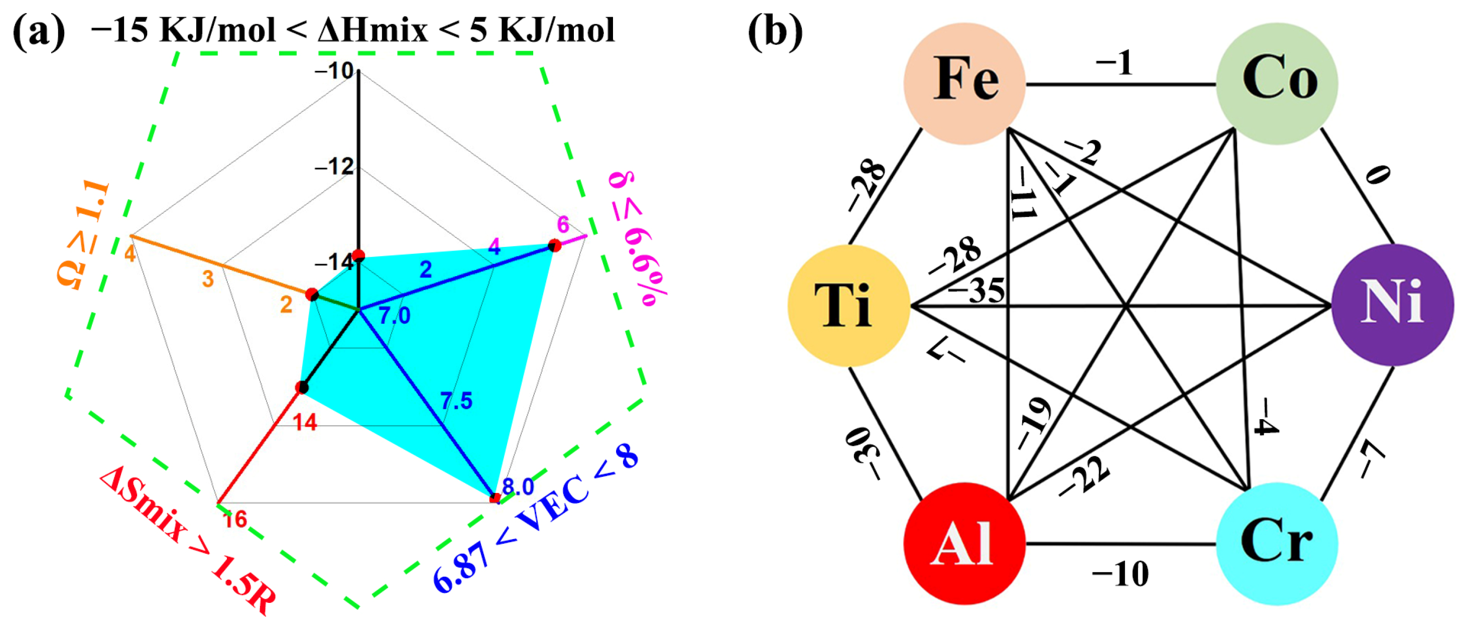
where ci and cj are the atomic fractions of elements i and j, ΔHij is the ΔHmix between elements i and j, R is the gas constant (8.314/(mol·K)), Tm is the melting temperature of the alloy, (Tm)i is the melting point of element i, ri is the atomic radius of element i, r ¯ is the weighted average radius of the elements, and (VEC)i is the valence electron concentration of element i. Based on these criteria, a dual-phase solid solution composed of FCC + BCC structure tends to form when ΔSmix > 1.5R (~12.47/(mol·K)), −15 KJ/mol < ΔHmix < 5 KJ/mol, δ ≤ 6.6%, 6.87 <VEC < 8, and Ω ≥ 1.1 [20]. As shown in Figure 5a, all parameters of the current Fe20Co25Ni31Cr8Al9Ti7 HEA are well within the acceptable values for maintaining an FCC + BCC dual-phase solid solution rather than an intermetallic compound, which is consistent with the current experimental results. It is worth noting that the VEC value of the Fe20Co25Ni31Cr8Al9Ti7 HEA is about 7.98, which is very close to the formation condition of a single FCC solid solution HEA (i.e., VEC ≥ 8). This is also why only a small amount of BCC phase is formed in the HEA-RL. In addition, this composition separation is reasonable from a thermodynamic point of view, as Al and Ti have a strong affinity with Ni due to the large negative ΔHmix between them. For example, the ΔHmix for Ti-Ni and Al-Ni is −35 and −22 kJ/mol [21], respectively (Figure 5b), meaning that Ti, Ni, and Al are prone to join together to form the BCC phase (which is similar to the Al-Ni solid-solution phase). On the contrary, other atoms with poor chemical affinities would be excluded from the BCC phase, leading to the formation of an FCC matrix rich in Fe and Cr.
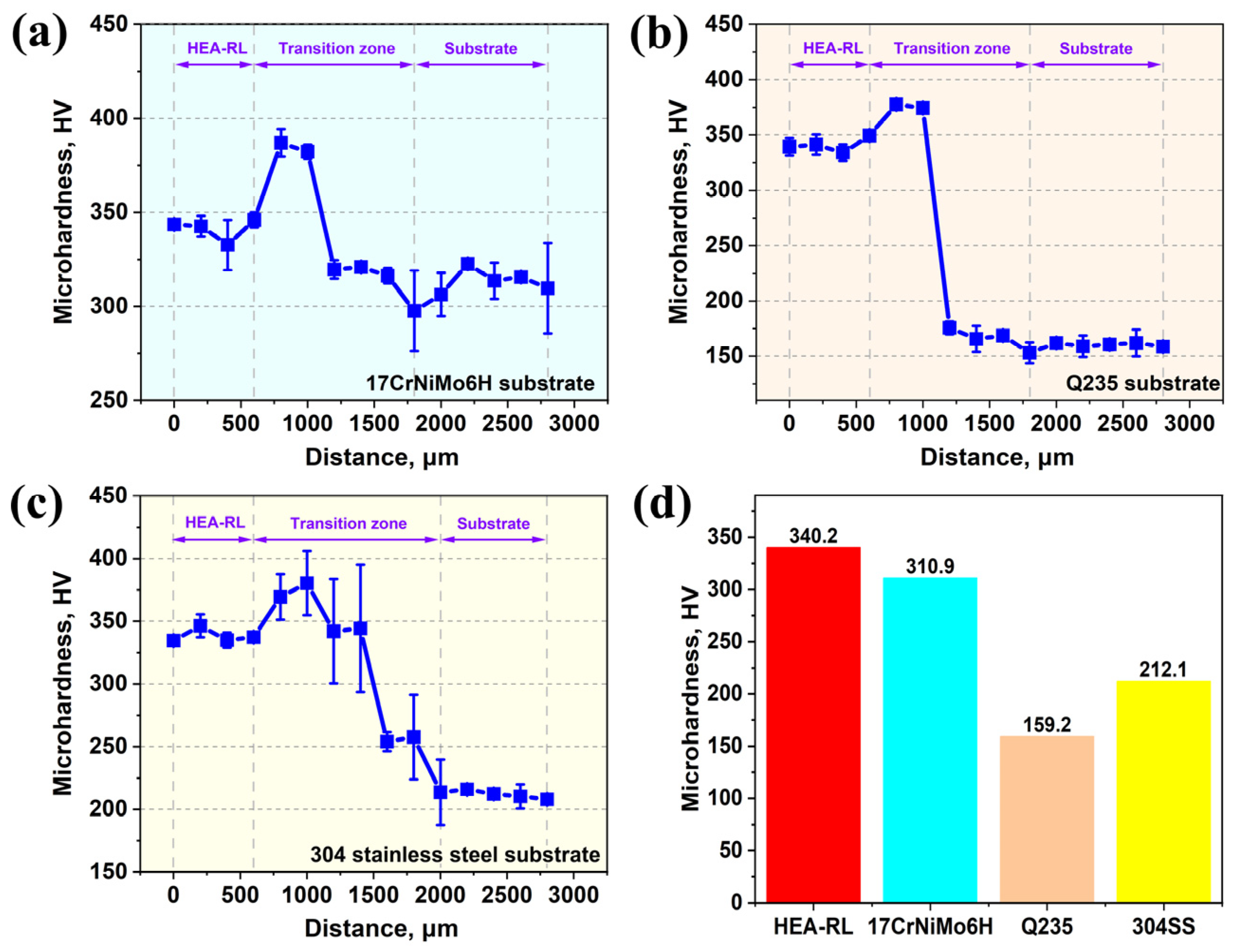
Figure 6a–c shows the microhardness profile near the repaired interface between the substrate and the HEA-RL. Some common features can be observed, which are characterized by the following: (1) The distribution of microhardness can be clearly divided into three zones: HEA-RL, transition zone, and substrate. (2) The overall microhardness of HEA-RL is greater than that of the substrate. As seen, the average hardness of HEA-RL is approximately 340 HV, which is equivalent to 1.1, 2.1, and 1.6 times that of the 17CrNiMo6H, Q235, and 304SS substrates, respectively (Figure 6d). Meanwhile, the microhardness value of the HEA layer is relatively stable, reflecting a uniformly distributed microstructure. (3) The highest microhardness values (~400 HV) all occur in the transition zone. These features are largely attributed to the following reasons. First, as shown in Figure 4d, the current HEA-RL is mainly composed of dominant FCC (~96.4%) and a small amount of BCC (~3.6%) phases. Therefore, from the perspective of strengthening mechanisms, solid-solution strengthening is expected to play a key role in improving microhardness. As is well known, the effect of solid-solution strengthening strongly depends on the lattice distortion caused by the difference in atomic radius between solvent atoms and solute atoms in the alloy [22]. The greater the lattice distortion, the more significant the solid-solution strengthening effect is usually. Taking the Q235 steel as an example, its composition is almost all Fe. In this case, the solid-solution strengthening effect is limited. On the contrary, the large difference of atomic radii in the HEA-RL (the radii of Ti and Al are 1.45 and 1.43 Å; those of Fe, Co, Cr, and Ni are 1.27, 1.25, 1.27, and 1.24 Å, respectively) will cause severe lattice distortion, contributing to a strong obstacle to dislocation slip, thus exhibiting the high microhardness. Second, it is generally accepted that the hardness of the BCC phase is higher than that of the FCC phase due to the fewer movable slip systems. Therefore, the presence of these hard BCC phases not only increases the strength of the cladding layer on their own but also induces the precipitation-strengthening effect [23]. Moreover, potential grain refinement caused by the rapid heating and cooling during the LC also provides a further guarantee for improving the microhardness of HEA-RL [24]. The much higher microhardness in the transition zone may be because some elements in the HEA-RL are diluted into the transition zone, resulting in the formation of new solid-solution phases with higher hardness [25]; however, further study is still needed. In summary, the above results strongly demonstrate the enormous potential of the current HEA coating in improving the wear resistance of traditional alloys such as the Q235 steel.
Figure 7a shows the PDP results of the repair layer and three substrates. The 17CrNiMo6H and Q235 substrates display active dissolution during the anodic polarization process, while the HEA-RL exhibits spontaneous passivation due to the absence of active–passive transition regions in the polarization curves, indicating that the corrosion resistance of HEA-RL is far superior to that of these two substrates. This high corrosion resistance is closely attributed to the formation of a protective passive film on the surface of the HEA-RL. Notably, the HEA-RL exhibits corrosion resistance comparable to that of the 304SS substrate due to their similar passive density and pitting potential, although the Cr content in the former is less than half of that in the latter.
To further compare the corrosion properties of the HEA-RL and three substrates, EIS tests were carried out. The EIS data reveal that the radius of the capacitive arc (Figure 7b) decreases in the following order: 304SS > HEA-RL > Q235 > 17CrNiMo6H, confirming the decent corrosion resistance of HEA-RL. Figure 7c shows the changes in impedance and phase with the EIS test frequency. In these plots, the high-frequency intercept corresponds to the electrolyte resistance while the low-frequency impedance reflects the corrosion resistance of the samples. The impedance amplitude at low frequency (i.e., 10 mHz) decreases in the same order as the radius of the capacitive arc, confirming the decent corrosion resistance of HEA-RL. The electrical equivalent circuit (EEC) shown in Figure 7b was selected to fit and analyze the EIS results. In this EEC, Rs, Rf, and Rct represent the resistance of solution, passive film, and charge transfer, respectively. Meanwhile, CPEf and CPEdl represent the corresponding capacitance response of the film and double layer, respectively. The EEC suggests that the superior corrosion resistance of HEA-RL is due to the formation of a protective passive film on the coating surface. This is because the existence of the Cr element in the HEA is beneficial for the formation of Cr-rich oxide, which is considered to play a critical role in determining corrosion resistance [26]. Importantly, the preferential dissolution of Al and Ti elements promotes the nucleation of Cr2O3 on the surface of Al2O3/TiO2 nuclei under heterogeneous nucleation, thereby significantly facilitating the nucleation rate of Cr2O3 [27]. This may give the HEA-RL comparable corrosion resistance to the 304SS substrate though it contains little Cr content. As shown in Figure 7d–g, there was no obvious corrosion for the HEA-RL and the 304SS substrate after polarization to 0 VSCE, while severe corrosion can be clearly observed on the 17CrNiMo6H and Q235 substrates.
In addition, Figure 8a,b shows the PSP curves at the potential of the 0 VSCE for the HEA-RL and three substrates. The current densities for the 17CrNiMo6H and Q235 substrates monotonously increase with the polarization time (Figure 8a), confirming the perishing corrosion resistance of these two alloys. Differently, the current densities for the HEA-RL and 304SS drop rapidly over time initially. Subsequently, the current densities decline gradually and stabilize at a relatively constant level (iss) (Figure 8b), indicating a relatively intact passive film formed upon the 304SS substrate and HEA-RL. The value of iss for the HEA-RL is slightly higher than that of 304SS, reflecting the degradation of the protective property for the passive films. Generally, the property of a passive film is closely related to its semiconductor characteristics. Therefore, Mott–Schottky measurements were carried out after the PSP tests to compare the difference between the passive films formed on 304SS and the HEA layer, and the results are shown in Figure 8c. Each plot of the HEA layer and 304SS exhibits a linear region with a positive slope in the passive range, meaning that the surface passive films on the two alloys exhibit n-type semiconductor properties in the 3.5 wt.% NaCl solution. The main point defects contained in an n-type semiconductor are oxygen vacancies and metal interstitials; they are the donors in the process of ionic charge migration through the passive film [28]. The measured capacitance of the n-type semiconductor in this work can be expressed as follows [29]:
1 C 2 = 2 ε r ε 0 e A N D E E FB k T e
where εr is the dielectric constant of the film, ε0 is the vacuum permittivity, ND is the donor density in an n-type passive film, e is the charge of an electron, E is the applied potential, EFB is the flat band potential, T is the temperature in Kelvin, A is the test area of the sample, and k is the Boltzmann constant. Through the calculated results, the average value of ND for the HEA layer is higher than that of 304SS, as shown in Figure 8d, reflecting a relatively more porous passive film formed on the surface of the HEA layer. Conversely, the average value of EFB for the HEA layer is a little lower than that of 304SS, implying a lower energy barrier for electron escape of the passive film on the HEA layer. These results indicate the protectiveness of the passive film on the HEA layer is slightly worse than that of 304SS. Therefore, it is still necessary to optimize the composition of the current HEA-RL, such as appropriately increasing the Cr content or adjusting the Al/Ti content. Nevertheless, the current study still demonstrates the great potential of HEA in intensive additive repair.
However, before concluding this article, it is necessary to emphasize that due to the rapid and repeated heating and cooling by high-energy laser beams and the unique thermal distribution induced by the layer-by-layer construction approach, the LC coatings possess potential microstructural anisotropy, including grain morphology, size, and orientation [30]. Generally speaking, grains have a preferred growth orientation along the temperature gradient, resulting in the formation of coarse columnar grains with {001} texture oriented along the build direction. This is also supported by the current research findings (Figure 2). Such a columnar structure tends to exhibit an equiaxed morphology on the transverse section (perpendicular to the build direction). This microstructural difference will result in the anisotropy of mechanical properties due to the difference in slip distances of dislocations in different directions. For example, along the transverse direction, higher strength is observed at the expense of reduced plasticity, whereas along the longitudinal direction, plasticity increases but strength decreases [31]. More importantly, it has been suggested that grain orientation has a significant impact on the propagation of sound [32] and light waves [33], as well as magnetic domains [34], resulting from the directional dependent feature of properties [35,36]. Consequently, further research is needed for the intensive repair of anisotropic materials.

4. Conclusions

This paper explores the intensive additive repair capability of an ameliorated Fe20Co25Ni31Cr8Al9Ti7 HEA by selecting three substrates (namely, 17CrNiMo6H, Q235, and 304SS), and the microstructure, microhardness, and corrosion properties of the HEA-RL were characterized. The main conclusions are presented below:
(1)
The HEA-RL prepared by laser cladding forms a metallurgical bond with the three substrates. The cladding layer is composed of a dominant (Fe, Cr)-rich FCC phase and a small amount of (Ni, Ti, and Al)-rich BCC phases. The high ΔSmix of the HEA-RL promotes the formation of simple solid-solution phases, but the strong affinity between Ti, Al, and Ni leads to the formation of BCC phases.
(2)
Compared to the three substrates, the HEA-RL shows much higher hardness, about 340 HV, which is 1.1, 2.1, and 1.6 times higher than the average hardness of the 17CrNiMo6H, Q235, and 304SS substrates, respectively. Such delightful hardness is attributed to the solid-solution strengthening effect and the dispersion-strengthening effect of the BCC phase.
(3)
The evaluation of corrosion performance reveals that the HEA-RL holds a corrosion resistance comparable to 304SS, which is much better than that of the 17CrNiMo6H and Q235 substrates, despite the fact that the Cr content in the HEA-RL is only half of that in 304SS. The presence of relatively high concentrations of Ti and Al is believed to play a key role in empowering the corrosion resistance of HEA-RL by promoting the heterogeneous nucleation of Cr2O3. Mott–Schottky’s analysis suggests that the passive film upon HEA-RL displays an n-type semiconductor property.

Author Contributions

H.Y.: investigation, writing—original draft, and formal analysis. B.L.: formal analysis. D.W.: investigation. G.H.: investigation. D.H.: supervision and writing—review and editing. B.Y.: conceptualization, supervision, resources, and project administration. All authors have read and agreed to the published version of the manuscript.

Funding

This work was supported by the National Key Research and Development Program of China (Nos. 2022YFF0609002), the China Postdoctoral Science Foundation (No. 2022M713210), and the Foundation of National Key Laboratory for Remanufacturing.

Institutional Review Board Statement

Not applicable.

Informed Consent Statement

Not applicable.

Data Availability Statement

The raw/processed data required to reproduce these findings are available from the corresponding author upon request.

Conflicts of Interest

The authors declare no conflicts of interest.

References

  1. Ning, J.; Zhang, H.B.; Chen, S.M.; Zhang, L.J.; Na, S.J. Intensive laser repair through additive manufacturing of high-strength martensitic stainless steel powders (I)–powder preparation, laser cladding and microstructures and properties of laser-cladded metals. J. Mater. Res. Technol. 2021, 15, 5746–5761. [Google Scholar] [CrossRef]
  2. Zhu, S.; Zhou, C.J. Additive remanufacturing for ‘made in China 2025’. Therm. Spray Technol. 2016, 8, 1–4. [Google Scholar]
  3. Zhang, Y.; Zuo, T.T.; Tang, Z.; Gao, M.C.; Dahmen, K.A.; Liaw, P.K.; Lu, Z.P. Microstructures and properties of high-entropy alloys. Prog. Mater. Sci. 2014, 61, 1–93. [Google Scholar] [CrossRef]
  4. Li, W.D.; Xie, D.; Li, D.Y.; Zhang, Y.; Gao, Y.T.; Liaw, P.K. Mechanical behavior of high-entropy alloys. Prog. Mater Sci. 2021, 118, 100777. [Google Scholar] [CrossRef]
  5. Zheng, Q.F.; Lu, W.Y.; Han, D.; Li, T.R.; Guo, H.; Qiu, K.Q.; Yang, B.J.; Wang, J.Q. Effect of Al content on microstructure, mechanical, and corrosion properties of (Fe33Cr36Ni15Co15Ti1)100-xAlx High-Entropy Alloys. Adv. Eng. Mater. 2024, 25, 2301013. [Google Scholar] [CrossRef]
  6. Liu, Z.C.; Kong, D.J. Microstructure, corrosive-wear and immersion corrosion performances of laser cladded FeCoNiMo(Al,Ti) high-entropy alloy coatings. Corros. Sci. 2024, 227, 111766. [Google Scholar]
  7. Su, J.L.; Li, A.; Ruan, Y.; Qiu, X.M.; Liang, J.W. Repair of tungsten heavy alloy die casting molds with laser cladded CoCrFeNiWx high entropy alloy Coatings: Microstructure, wear properties and tempering stability. Eng. Fail. Anal. 2024, 161, 108291. [Google Scholar] [CrossRef]
  8. Qiu, X. Microstructure and mechanical properties of CoCrFeNiMo high-entropy alloy coatings. Mater. Res. Technol. 2020, 9, 5127–5133. [Google Scholar] [CrossRef]
  9. Yang, Y.; Li, Z.; Dong, J.W.; Luo, Z. Enhancing performance and microstructure analysis in laser welded of R60702 zirconium alloy and 304 stainless steel with TA2/Q235 composite interlayer. Mater. Lett. 2024, 359, 135960. [Google Scholar] [CrossRef]
  10. Bian, X.X.; Liu, Y.R.; Zhang, J.T. Fracture analysis on involute spline of large tunnel boring machine. Eng. Fail. Anal. 2022, 142, 106728. [Google Scholar] [CrossRef]
  11. Wang, J.N.; Liu, K.Y.; Xue, X.Y.; Li, J.S.; Chen, B. Columnar-to-equiaxed transition mechanism and remarkable strengthening effect in additive manufactured pure titanium induced by copper addition. Mater. Charact. 2024, 209, 113750. [Google Scholar] [CrossRef]
  12. Zhao, W.J.; Sun, Y.G.; Che, P.C.; Ning, Z.L.; Fan, H.B.; Yang, H.Y.; Sun, J.F.; Liaw, P.K.; Ngan, A.H.; Huang, Y.J. The columnar to equiaxed transition of CoCrNi medium-entropy alloy fabricated by laser directed energy deposition. Mater. Des. 2024, 237, 112538. [Google Scholar] [CrossRef]
  13. Kurz, W.; Bezençon, C.; Gäumann, M. Columnar to equiaxed transition in solidification processing. Sci. Technol. Adv. Mater. 2001, 2, 185–191. [Google Scholar] [CrossRef]
  14. Xiang, S.; Luan, H.; Wu, J.; Yao, K.F.; Li, J.F.; Liu, X.; Tian, Y.Z.; Mao, W.L.; Bai, H.; Le, G.M. Microstructures and mechanical properties of CrMnFeCoNi high entropy alloys fabricated using laser metal deposition technique. J. Alloy Compd. 2019, 773, 387–392. [Google Scholar] [CrossRef]
  15. He, R.; Wu, M.P.; Cui, C.; Jie, D.D.; Gong, Y.L.; Miao, X.J. Microstructure evolution, mechanical properties of FeCrNiMnAl high entropy alloy coatings fabricated by laser cladding. Surf. Coat. Tech. 2022, 447, 128851. [Google Scholar]
  16. Zhang, W.; Chabok, A.; Kooi, B.J.; Pei, Y.T. Additive manufactured high entropy alloys: A review of the microstructure and properties. Mater. Des. 2022, 220, 110875. [Google Scholar] [CrossRef]
  17. Zhou, Y.K.; Kang, J.J.; Zhang, J.; Fu, Z.Q.; Zhu, L.N.; She, D.S.; Yue, W. Microstructure and sliding wear behavior of HVOF sprayed Al(1−x)CoCrFeNiTix high-entropy alloy coatings. Mater. Lett. 2022, 314, 131929. [Google Scholar] [CrossRef]
  18. Oñate, A.; Sanhueza, J.P.; Ramirez, J.; Medina, C.; Melendrez, M.F.; Rojas, D. Design of Fe36.29Cr28.9Ni26.15Cu4.17Ti1.67V2.48C0.46 HEA using a new criterion based on VEC: Microstructural study and multiscale mechanical response. Mater. Today Commun. 2023, 35, 105681. [Google Scholar] [CrossRef]
  19. Zheng, W.; Lü, S.; Wu, S.; Chen, X.; Guo, W. Development of MoNbVTax refractory high entropy alloy with high strength at elevated temperature. Mater. Sci. Eng. A 2022, 850, 143554. [Google Scholar] [CrossRef]
  20. Guan, Y.J.; Cui, X.F.; Chen, D.; Su, W.N.; Zhao, Y.; Li, J.; Feng, L.T.; Li, X.Y.; Jin, G. Realizing excellent tribological properties of BCC/FCC gradient high -entropy alloy coating via an in-situ interface reaction. Mater. Today Commun. 2023, 35, 106098. [Google Scholar] [CrossRef]
  21. Takeuchi, A.; Inoue, A. Classification of bulk metallic glasses by atomic size difference, heat of mixing and period of constituent elements and its ap-plication to characterization of the main alloying element. Mater. Trans. 2005, 46, 2817–2829. [Google Scholar] [CrossRef]
  22. Aidhy, D.S. Chemical randomness, lattice distortion and the wide distributions in the atomic level properties in high entropy alloys. Comp. Mater. Sci. 2024, 237, 112912. [Google Scholar] [CrossRef]
  23. Hao, X.H.; Liu, H.X.; Zhang, X.W.; Chen, L.; Wang, Y.Y.; Yang, C.; Liu, Y.X. Friction-wear behaviors and microstructure of AlTiVCrNb lightweight refractory high-entropy alloy coating prepared by laser cladding on Ti-6Al-4V substrate. J. Mater. Res. Technol. 2024, 29, 1–11. [Google Scholar] [CrossRef]
  24. Chen, B.; Li, X.M.; Tian, L.Y.; Jia, H.Y.; Li, H.; Li, Y.J. The CrFeNbTiMox refractory high-entropy alloy coatings prepared on the 40Cr by laser cladding. J. Alloy Compd. 2023, 966, 171630. [Google Scholar] [CrossRef]
  25. Feng, M.Y.; Lin, T.X.; Lian, G.F.; Chen, C.R.; Huang, X.J. Effects of Nb content on the microstructure and properties of CoCrFeMnNiNbx high-entropy alloy coatings by laser cladding. Mater. Res. Technol. 2024, 28, 3835–3848. [Google Scholar] [CrossRef]
  26. Sun, M.; Yang, Z.N.; Song, S.C.; Zhang, J.X.; Lu, B.H. Effect of Cr content on microstructure, mechanical, and corrosion properties of CoCrxFeMnNi high-entropy alloys fabricated by selective laser melting. Mater. Charact. 2024, 212, 113949. [Google Scholar] [CrossRef]
  27. Zhang, C.L.; Huang, L.F.; Li, S.X.; Li, K.; Lu, S.Y.; Li, J.F. Improved corrosion resistance of laser melting deposited CoCrFeNi series high-entropy alloys by Al addition. Corro. Sci. 2023, 225, 111599. [Google Scholar] [CrossRef]
  28. Gu, X.H.; Li, X.R.; Zhang, Q.H.; Wu, L.K.; Cao, F.H. Passive film and surface characterization of Alx(CoCrFeNi)100-x (x = 0, 5, 10, 15, 20) high entropy alloys. Intermetallics 2023, 162, 107994. [Google Scholar] [CrossRef]
  29. Wang, G.Y.; Xu, J.; Chen, Y.H.; Zhao, Y.J.; Xie, Z.H.; Munroe, P.R. Assessment of the tribocorrosion performance of a (TiZrNbTaMo)C refractory high entropy alloy carbide coating in a marine environment. J. Alloys Compd. 2023, 965, 171342. [Google Scholar] [CrossRef]
  30. Koka, Y.; Tana, X.P.; Wang, P.; Nai, M.L.S.; Loh, N.H.; Liu, E.; Tor, S.B. Anisotropy and heterogeneity of microstructure and mechanical properties in metal additive manufacturing: A critical review. Mater. Des. 2018, 139, 565–586. [Google Scholar] [CrossRef]
  31. Carroll, B.E.; Palmer, T.A.; Beese, A.M. Anisotropic tensile behavior of Ti-6Al-4V components fabricated with directed energy deposition additive manufacturing. Acta Mater. 2015, 87, 309–320. [Google Scholar] [CrossRef]
  32. Wang, C.; Gao, P.F.; Liu, T.; Li, L.F.; Wang, E.Z.; Wang, Q. Microstructure and wear performance of Ni-10 wt.%Al coatings plasma sprayed on Ni-based superalloys with a sound field. Surf. Coat. Tech. 2019, 370, 157–162. [Google Scholar] [CrossRef]
  33. Safaie, H.; Coleman, M.; Johnston, R.; Das, A.; Russell, J.; Pleydell-Pearce, C. Circular polarized light microscopy to investigate the crystal orientation of aluminium. Mater. Charact. 2022, 185, 111749. [Google Scholar] [CrossRef]
  34. Nadoum, A.; Robinson, F.; Birosca, S.J. On the correlation between magnetic domain and crystallographic grain orientation in grain oriented electrical steels. Magn. Magn. Mater. 2020, 494, 165772. [Google Scholar] [CrossRef]
  35. Zhu, J.L.; An, Z.Q.; Zhang, A.X.; Du, Y.K.; Zhou, X.; Geng, Y.Z.; Chen, G.F. Anisotropic porous designed polymer coatings for high-performance passive all-day radiative cooling. iScience 2022, 25, 104126. [Google Scholar] [CrossRef]
  36. Valagiannopoulos, C.A. Study of an electrically anisotropic cylinder excited magnetically by a straight strip line Electromagn. Prog. Electromagn Res. 2007, 73, 297–325. [Google Scholar] [CrossRef]
Figure 1. SEM images (a,b), particle size distribution (c), and EDS mapping (d) of the HEA powder.
Coatings 14 01068 g001
Figure 2. SEM images of the cross-section of the HEA-RL attained by single-layer single-pass cladding. Overall cross-sectional profiles (a,b,c), bottom regions (a1,b1,c1), and top regions (a2,b2,c2) for the 17CrNiMo6H (a), Q235 (b), and 304SS (c) substrates.
Coatings 14 01068 g002
Figure 3. SEM images (a,b,c) and EDS mapping (df) of the cross-section of the HEA-RL attained by six-layer multi-pass cladding for the 17CrNiMo6H (a,d), Q235 (b,e), and 304SS (c,f) substrates.
Coatings 14 01068 g003
Figure 4. XRD patterns (a) and SEM backscattering electron image (b) of the microstructure of the HEA-RL; (c) EDS line scan, corresponding to the solid blue line in (b); (d) EBSD phase maps of the HEA-RL.
Coatings 14 01068 g004
Figure 5. (a) Radar map of the criteria used for phase selection in dual-phase HEAs and (b) enthalpy of mixing between elements in the Fe20Co25Ni31Cr8Al9Ti7 HEA.
Coatings 14 01068 g005
Figure 6. Microhardness distribution near the repaired interface between the substrate and HEA-RL: (a) 17CrNiMo6H, (b) Q235, (c) 304SS, and (d) statistical results.
Coatings 14 01068 g006
Figure 7. Corrosion performance of the HEA-RL and three substrates in 3.5 wt.% NaCl solution: (a) polarization curves, (b) Nyquist plots, (c) Bode plots; and corrosion morphologies (dg) of HEA-RL and the three substrates after polarization to 0 VSCE.
Coatings 14 01068 g007
Figure 8. The PSP curves of the (a) Q235 and 17CrNiMo6h and (b) HEA layer and 304SS; (c) Mott–Schottky results of the HEA layer and 304SS; and (d) variation in the ND and EFB values for the HEA layer and 304SS.
Coatings 14 01068 g008
Table 1. Compositions (wt.%) of different substrates.
Type of SubstratesCSiMnPSCrNiMoFe
Q2350.150.351.200.0450.050---Bal.
304SS0.081.002.000.0450.03018.0–20.08.0–11.0-Bal.
17CrNiMo6H0.200.400.600.0350.0351.501.700.35Bal.
Disclaimer/Publisher’s Note: The statements, opinions and data contained in all publications are solely those of the individual author(s) and contributor(s) and not of MDPI and/or the editor(s). MDPI and/or the editor(s) disclaim responsibility for any injury to people or property resulting from any ideas, methods, instructions or products referred to in the content.