

Self-Healing and Thermal Stability of LaMgAl11O19-Ti3AlC2 Composites for High-Temperature Abradable Applications
 ,
,
Abstract
:1. Introduction
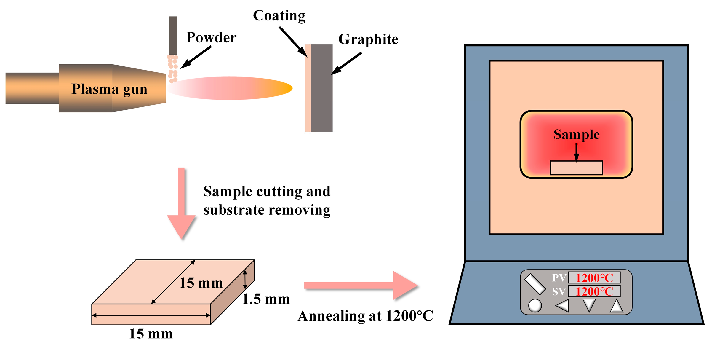
2. Methodology
3. Results and Discussion
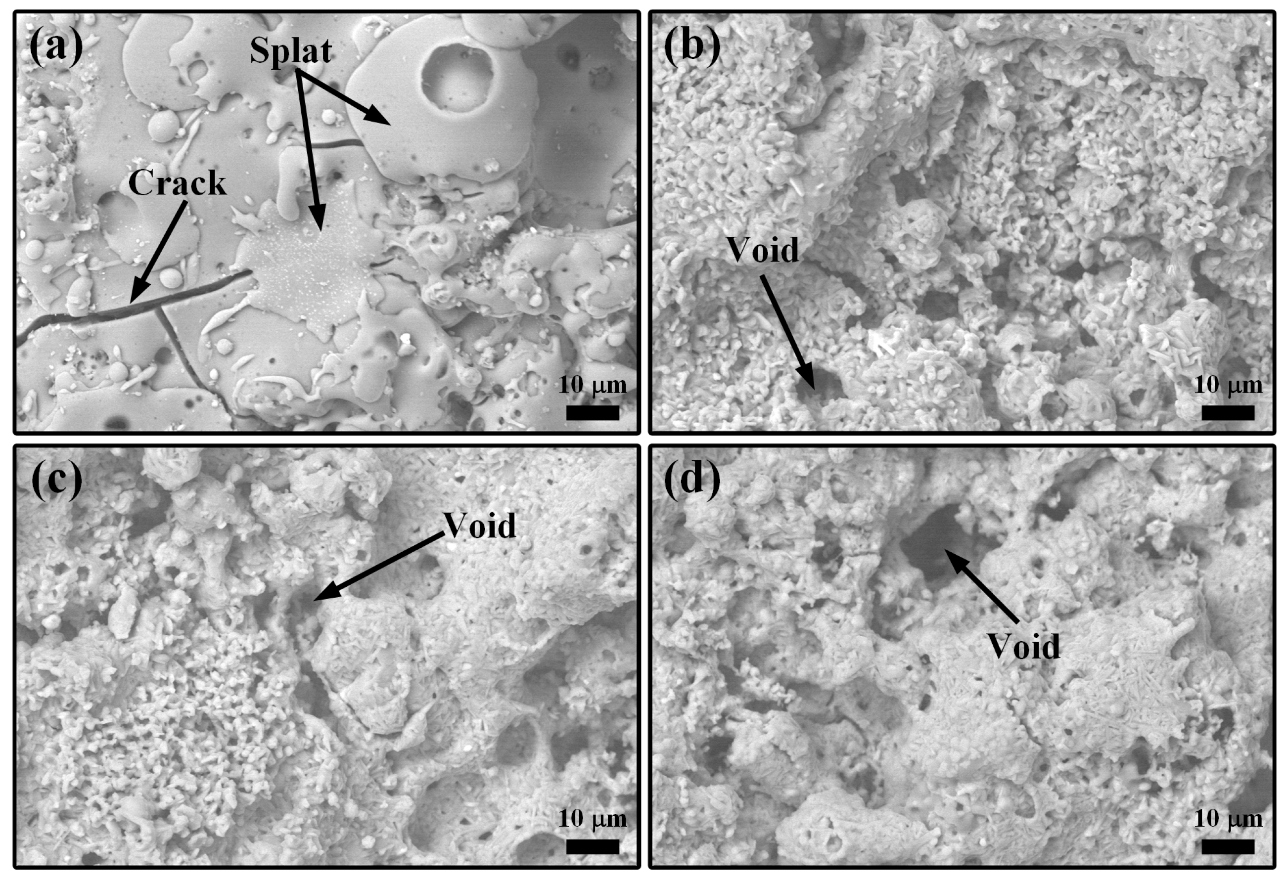
3.1. LMA-Based Composite Coatings after Annealing at 1200 °C
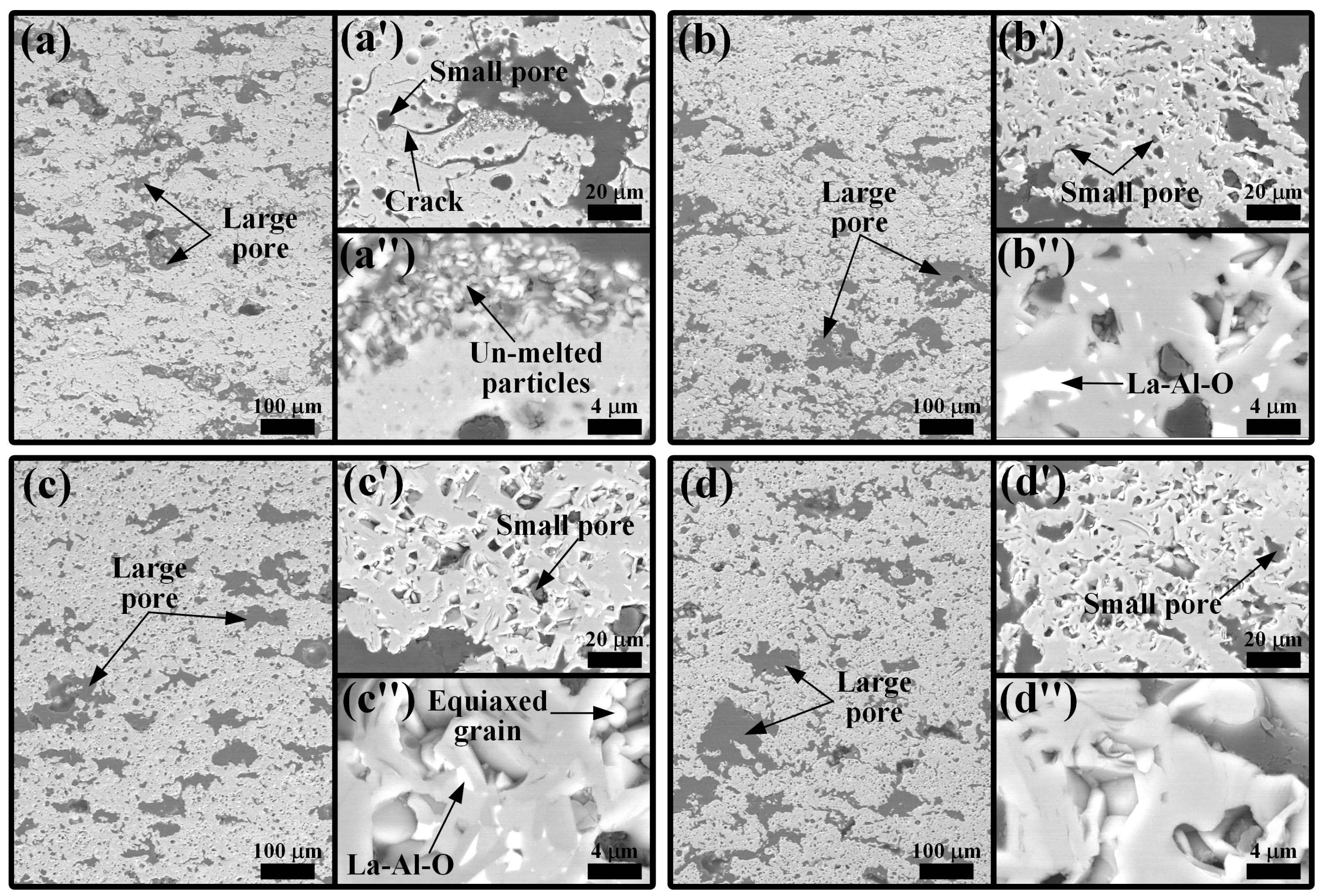
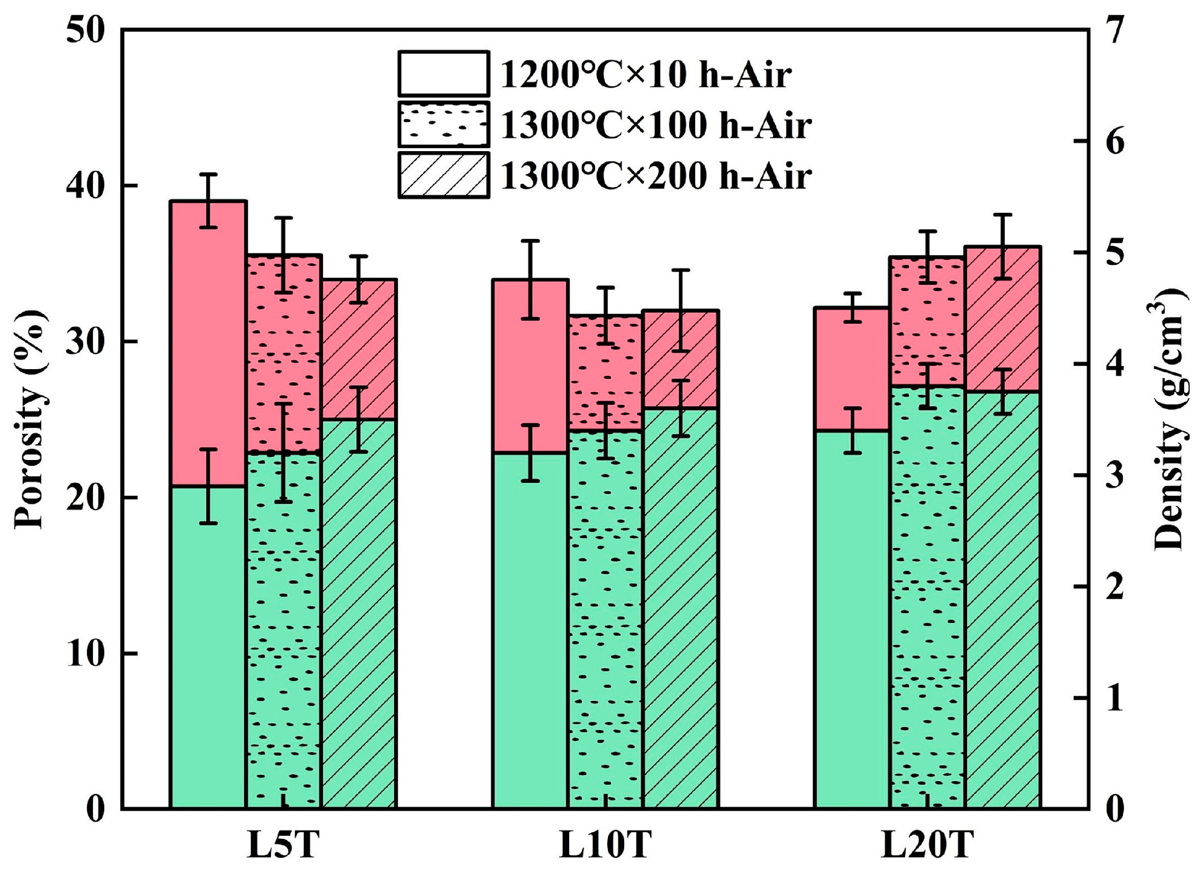
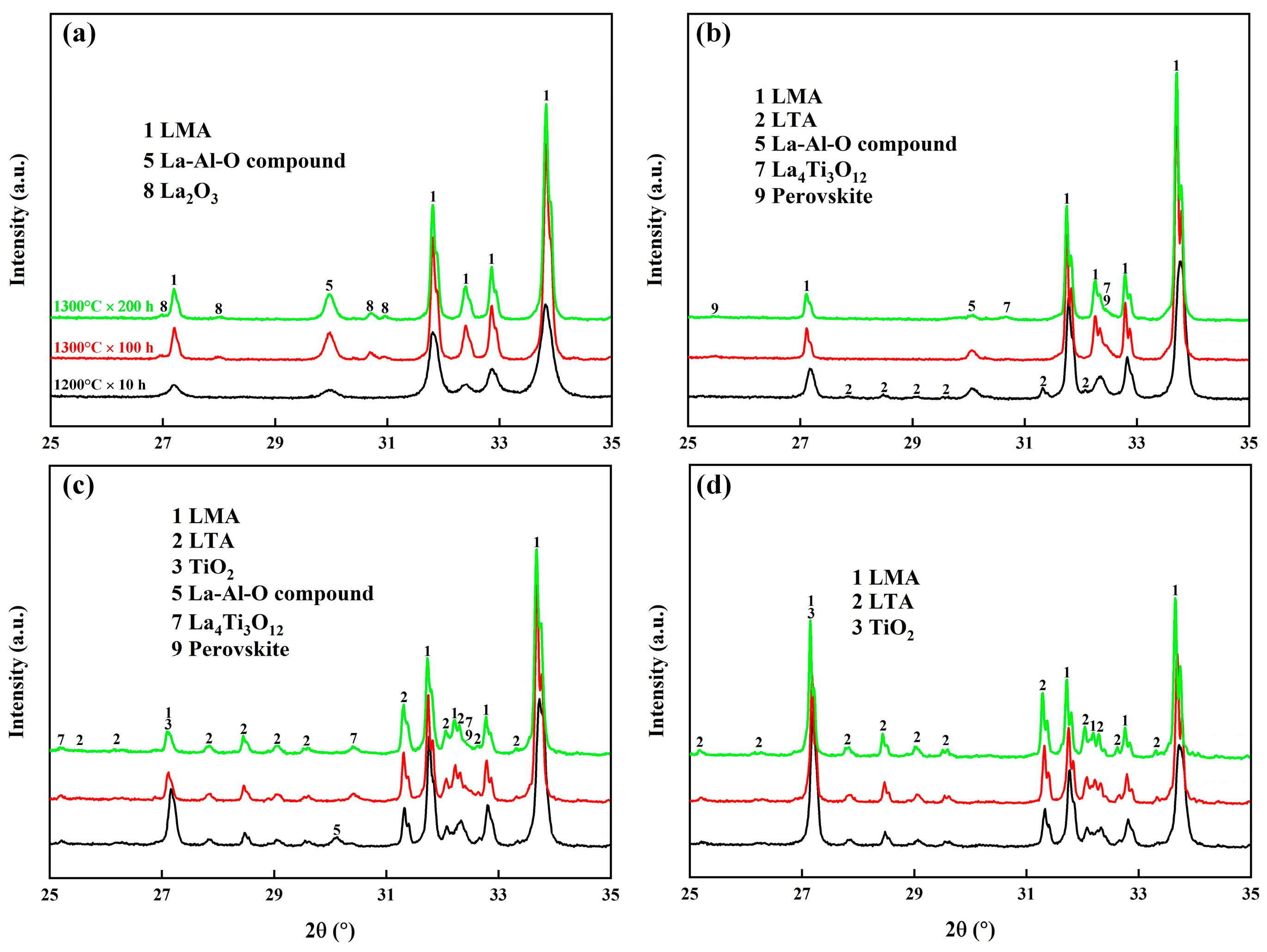
3.2. LMA-Based Composite Coatings after Air Oxidation at 1300 °C
3.3. LMA-Based Composite Coatings after Steam Corrosion at 1300 °C
4. Conclusions
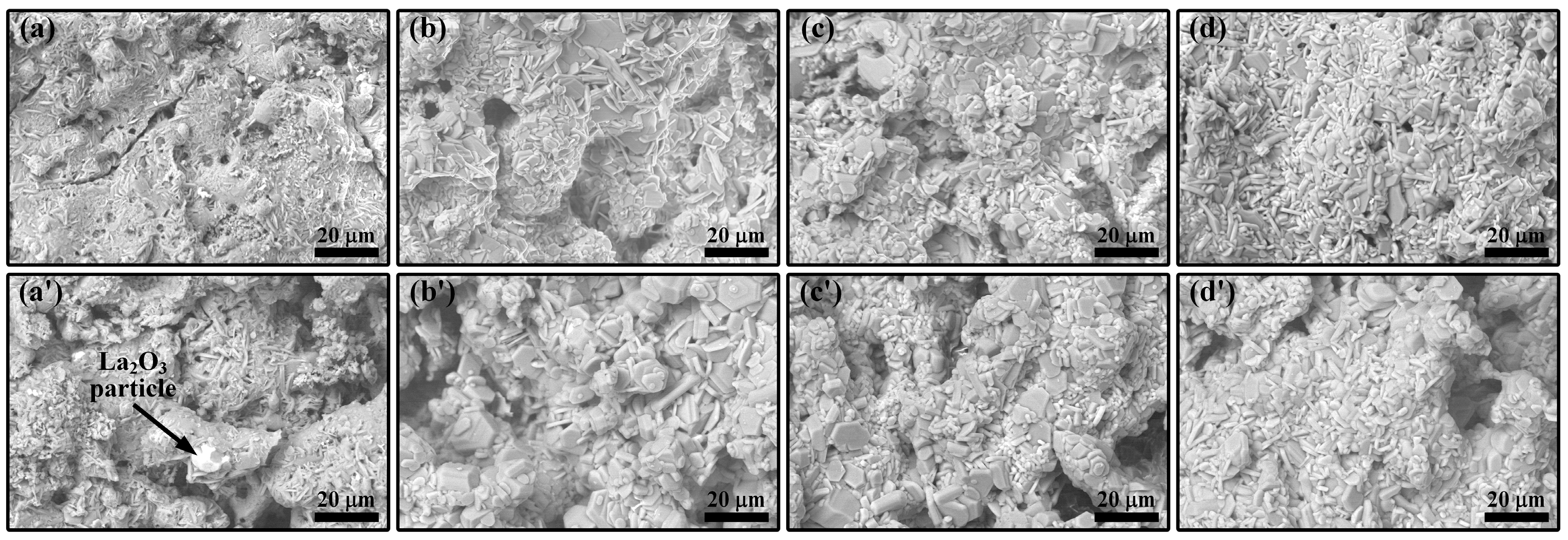
- The oxidation of TAC at 1200 °C produced rutile TiO2 and Al2O3, which accelerated sintering, promoted the growth of LMA grains, and reacted with the La-rich secondary phase in the coatings to form LTA. With the increase in TAC content, the coating porosity decreased, and the density increased, converting interconnected pores into isolated ones, while cracks gradually closed.
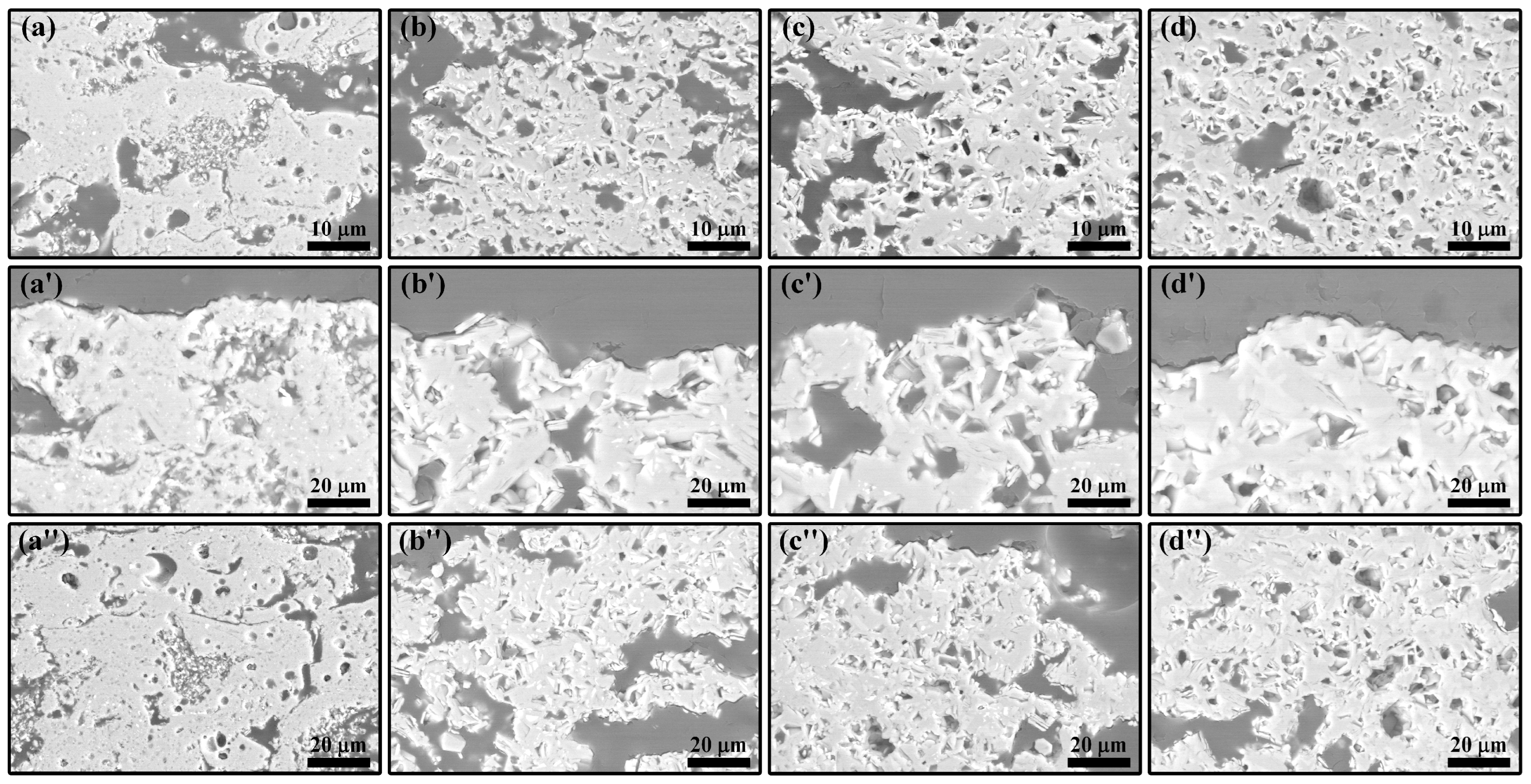
- During air oxidation at 1300 °C, the residual TAC in the coatings continued to oxidize, causing a slight weight gain. Excess TiO2 led to the formation of the La4Ti3O12 phase. In the composite coatings with higher TAC content, LMA platelet-like grains gradually transformed into equiaxed ones with the oxidation time, and the porosity of the coatings increased.
- During steam corrosion at 1300 °C, due to the selective volatilization of Al, LTA gradually decomposed to form the α-La2/3TiO3 phase, which further decomposed to produce the La4Ti3O12 phase. The accelerated mass-transfer effect of steam further increased the thickness of the LMA grains. The steam also caused corrosion within the coatings through the porous structure of the composite coatings. Among them, the composite coating containing 20 wt.% TAC shows the most outstanding stability, indicating its potential as a novel high-temperature abradable material.
Author Contributions
Funding
Institutional Review Board Statement
Informed Consent Statement
Data Availability Statement
Conflicts of Interest
References
- Sporer, D.; Wilson, S.; Giovannetti, I.; Refke, A.; Giannozzi, M. On The Potential of Metal and Ceramic Based Abradables in Turbine Seal Applications. In Proceedings of the Thirty-Sixth Turbomachinery Symposium, College Station, Texas, USA, 11–13 September 2007; Texas A&M University: College Station, TX, USA, 2007; pp. 79–86. [Google Scholar] [CrossRef]
- Bardi, U.; Giolli, C.; Scrivani, A.; Rizzi, G.; Borgioli, F.; Fossati, A.; Partes, K.; Seefeld, T.; Sporer, D.; Refke, A. Development and Investigation on New Composite and Ceramic Coatings as Possible Abradable Seals. J. Therm. Spray Technol. 2008, 17, 805–811. [Google Scholar] [CrossRef]
- Vaßen, R.; Bakan, E.; Mack, D.E.; Guillon, O. A Perspective on Thermally Sprayed Thermal Barrier Coatings: Current Status and Trends. J. Therm. Spray Technol. 2022, 31, 685–698. [Google Scholar] [CrossRef]
- Aussavy, D.; Bolot, R.; Montavon, G.; Peyraut, F.; Szyndelman, G.; Gurt-Santanach, J.; Selezneff, S. YSZ-Polyester Abradable Coatings Manufactured by APS. J. Therm. Spray Technol. 2016, 25, 252–263. [Google Scholar] [CrossRef]
- Sporer, D.R.; Taeck, U.; Dorfman, M.R.; Nicoll, A.R.; Giannozzi, M.; Giovannetti, I. Novel Ceramic Abradable Coatings with Enhanced Performance. In Proceedings of the ASME Turbo Expo 2006: Power for Land, Sea, and Air, Barcelona, Spain, 8–11 May 2006; pp. 1017–1023. [Google Scholar]
- Biesiadny, T.J.; Klann, G.A.; Lassow, E.S.; Mchenry, M.; Mcdonald, G.; Hendricks, R.C. Experimental Study of Ceramic-Coated Tip Seals for Turbojet Engines. In Proceedings of the 9th Annual Conference on Composites and Advanced Ceramic Materials: Ceramic Engineering and Science Proceedings, Cocoa Beach, FL, USA, 20–24 January 1985. [Google Scholar]
- Cao, X.Q.; Vassen, R.; Stoever, D. Ceramic materials for thermal barrier coatings. J. Eur. Ceram. Soc. 2004, 24, 1–10. [Google Scholar] [CrossRef]
- Sun, J.; Wang, J.; Zhou, X.; Hui, Y.; Dong, S.; Li, L.; Deng, L.; Jiang, J.; Cao, X. Thermal cycling behavior of the plasma-sprayed coating of lanthanum hexaaluminate. J. Eur. Ceram. Soc. 2018, 38, 1919–1929. [Google Scholar] [CrossRef]
- Sun, J.; Wang, J.; Zhang, H.; Yuan, J.; Dong, S.; Jiang, J.; Deng, L.; Zhou, X.; Cao, X. Preparation, structure, mechanical properties and thermal cycling behavior of porous LaMgAl11O19 coating. J. Alloys Compd. 2018, 750, 1007–1016. [Google Scholar] [CrossRef]
- Sun, J.; Wang, J.; Zhou, X.; Dong, S.; Deng, L.; Jiang, J.; Cao, X. Microstructure and thermal cycling behavior of plasma-sprayed LaMgAl11O19 coatings. Ceram. Int. 2018, 44, 5572–5580. [Google Scholar] [CrossRef]
- Huang, J.; Chen, W.; Lu, X.; Xu, M.; Li, G.; Deng, L.; Jiang, J.; Dong, S.; Liu, L.; Chen, M.; et al. Isothermal Oxidation and Thermal Shock Resistance of Thick and Porous LaMgAl11O19 Abradable Topcoat. Coatings 2024, 14, 426. [Google Scholar] [CrossRef]
- Sporer, D.; Wilson, S.; Dorfman, M. Ceramics for Abradable Shroud Seal Applications. Ceram. Eng. Sci. Proc. 2009, 4, 39–54. [Google Scholar] [CrossRef]
- Laverty, W.F. Rub energetics of compressor blade tip seals. Wear 1982, 75, 1–20. [Google Scholar] [CrossRef]
- Sun, J.; Hui, Y.; Jiang, J.; Deng, L.; Cao, X. Crystallization mechanism of plasma-sprayed LaMgAl11O19 coating. Appl. Surf. Sci. 2020, 504, 144509. [Google Scholar] [CrossRef]
- Evans, A.G.; Hutchinson, J.W. The mechanics of coating delamination in thermal gradients. Surf. Coat. Technol. 2007, 201, 7905–7916. [Google Scholar] [CrossRef]
- Lee, G.W.; Kim, T.W.; Sloof, W.G.; Lee, K.S. Self-healing capacity of Mullite-Yb2SiO5 environmental barrier coating material with embedded Ti2AlC MAX phase particles. Ceram. Int. 2021, 47, 22478–22486. [Google Scholar] [CrossRef]
- Ando, K.; Chu, M.-C.; Tsuji, K.; Hirasawa, T.; Kobayashi, Y.; Sato, S. Crack healing behaviour and high-temperature strength of mullite/SiC composite ceramics. J. Eur. Ceram. Soc. 2002, 22, 1313–1319. [Google Scholar] [CrossRef]
- Osada, T.; Kamoda, K.; Mitome, M.; Hara, T.; Abe, T.; Tamagawa, Y.; Nakao, W.; Ohmura, T. A Novel Design Approach for Self-Crack-Healing Structural Ceramics with 3D Networks of Healing Activator. Sci. Rep. 2017, 7, 17853. [Google Scholar] [CrossRef] [PubMed]
- Tavangarian, F.; Li, G. Bio-inspired crack self-healing of SiC/spinel nanocomposite. Ceram. Int. 2015, 41, 2828–2835. [Google Scholar] [CrossRef]
- Houjou, K.; Ando, K.; Takahashi, K. Crack-healing behaviour of ZrO2/SiC composite ceramics. Int. J. Struct. Integr. 2010, 1, 73–84. [Google Scholar] [CrossRef]
- Mohanty, D.; Sil, A.; Maiti, K. Development of input output relationships for self-healing Al2O3/SiC ceramic composites with Y2O3 additive using design of experiments. Ceram. Int. 2011, 37, 1985–1992. [Google Scholar] [CrossRef]
- Osada, T.; Nakao, W.; Takahashi, K.; Ando, K. Kinetics of Self-Crack-Healing of Alumina/Silicon Carbide Composite Including Oxygen Partial Pressure Effect. J. Am. Ceram. Soc. 2009, 92, 864–869. [Google Scholar] [CrossRef]
- Yuan, M.; Liu, L.; Wang, J.; Hu, Q.; Zhang, H.; Zhang, S.; Zhou, X. Crack-healing behaviour of MoSi2 dispersed Yb2Si2O7 environmental barrier coatings. Ceram. Int. 2022, 48, 29919–29928. [Google Scholar] [CrossRef]
- Liu, C.; Cai, C.; Xie, J.; Guo, W.; Qin, H.; Gao, P.; Xiao, H. Effect of surface brittle-to-ductile transition on high-temperature thermal shock resistance of Al2O3 ceramics. Ceram. Int. 2022, 48, 20627–20638. [Google Scholar] [CrossRef]
- Yu, H.; Suo, X.; Gong, Y.; Zhu, Y.; Zhou, J.; Li, H.; Eklund, P.; Huang, Q. Ti3AlC2 coatings deposited by liquid plasma spraying. Surf. Coat. Technol. 2016, 299, 123–128. [Google Scholar] [CrossRef]
- Wang, X.H.; Li, F.Z.; Chen, J.X.; Zhou, Y.C. Insights into high temperature oxidation of Al2O3-forming Ti3AlC2. Corros. Sci. 2012, 58, 95–103. [Google Scholar] [CrossRef]
- Tang, C.; Steinbrück, M.; Große, M.; Bergfeldt, T.; Seifert, H.J. Oxidation behavior of Ti2AlC in the temperature range of 1400 °C–1600 °C in steam. J. Nucl. Mater. 2017, 490, 130–142. [Google Scholar] [CrossRef]
- Lin, Z.J.; Li, M.S.; Wang, J.Y.; Zhou, Y.C. Influence of water vapor on the oxidation behavior of Ti3AlC2 and Ti2AlC. Scr. Mater. 2008, 58, 29–32. [Google Scholar] [CrossRef]
- Yang, H.J.; Pei, Y.T.; Rao, J.C.; De Hosson, J.T.M. Self-healing performance of Ti2AlC ceramic. J. Mater. Chem. 2012, 22, 8304–8313. [Google Scholar] [CrossRef]
- Song, G.M.; Pei, Y.T.; Sloof, W.G.; Li, S.B.; De Hosson, J.T.M.; van der Zwaag, S. Oxidation-induced crack healing in Ti3AlC2 ceramics. Scr. Mater. 2008, 58, 13–16. [Google Scholar] [CrossRef]
- Chen, H.; Hu, B.; Wang, J.; Wang, J.; Gao, Y. Tribological properties of self-healing NiCrAlY/Cr3C2-Ti3AlC2 coating at high temperatures. Surf. Coat. Technol. 2023, 465, 129610. [Google Scholar] [CrossRef]
- Boatemaa, L.; van der Zwaag, S.; Sloof, W.G. Self-healing of Al2O3 containing Ti microparticles. Ceram. Int. 2018, 44, 11116–11126. [Google Scholar] [CrossRef]
- Ma, J.; Hao, J.; Fu, L.; Qiao, Z.; Yang, J.; Liu, W.; Bi, Q. Intrinsic self-lubricity of layered Ti3AlC2 under certain vacuum environment. Wear 2013, 297, 824–828. [Google Scholar] [CrossRef]
- Zhao, H.; Feng, Y.; Qian, G.; Huang, X.; Guo, S.; Sun, X. Effect of Ti3AlC2 Content on Electrical Friction and Wear Behaviors of Cu–Ti3AlC2 Composites. Tribol. Lett. 2019, 67, 96. [Google Scholar] [CrossRef]
- Sun, J.; Wang, J.; Dong, S.; Hui, Y.; Li, L.; Deng, L.; Jiang, J.; Zhou, X.; Cao, X. Effect of heat treatment on microstructure and property of plasma-sprayed lanthanum hexaaluminate coating. J. Alloys Compd. 2018, 739, 856–865. [Google Scholar] [CrossRef]
- Wang, X.H.; Zhou, Y.C. Oxidation behavior of Ti3AlC2 powders in flowing air. J. Mater. Chem. 2002, 12, 2781–2785. [Google Scholar] [CrossRef]
- Zhao, K.; Dong, S.; Lü, K.; Chen, T.; Huang, Y.; Hu, Q.; Jiang, J.; Deng, L.; Cao, X. Feasibility research of Yb3Al5O12 garnet as environmental barrier coating materials. Ceram. Int. 2023, 49, 15413–15421. [Google Scholar] [CrossRef]
- Li, G.; Qin, L.; Cao, X.; Lu, X.; Tu, Y.; Zhang, H.; Jiang, J.; Deng, L.; Dong, S.; Liu, L.; et al. Water vapor corrosion resistance and failure mechanism of SiCf/SiC composites completely coated with plasma sprayed tri-layer EBCs. Ceram. Int. 2022, 48, 7082–7092. [Google Scholar] [CrossRef]
- Qian, X.K.; He, X.D.; Li, Y.B.; Sun, Y.; Li, H.; Xu, D.L. Cyclic oxidation of Ti3AlC2 at 1000–1300 °C in air. Corros. Sci. 2011, 53, 290–295. [Google Scholar] [CrossRef]
- Song, G.M.; Pei, Y.T.; Sloof, W.G.; Li, S.B.; De Hosson, J.T.M.; van der Zwaag, S. Early stages of oxidation of Ti3AlC2 ceramics. Mater. Chem. Phys. 2008, 112, 762–768. [Google Scholar] [CrossRef]
- Hu, Q.; Liu, R.; Guo, X.; Wei, H.; Tu, Y.; Wang, Y.; Song, G.; Lu, X.; Huang, J.; Xu, M.; et al. Thermal cycling behavior of Si/Yb2SiO5/LaMgAl11O19 TEBCs coated SiCf/SiC composites under burner rig tests. Ceram. Int. 2022, 48, 28082–28091. [Google Scholar] [CrossRef]
- Chen, X.; Sun, Y.; Hu, J.; Li, J.; Deng, C.; Wu, D.; Zeng, D.; Li, W.; Liu, Y.; Zou, B.; et al. Thermal cycling failure of the multilayer thermal barrier coatings based on LaMgAl11O19/YSZ. J. Eur. Ceram. Soc. 2020, 40, 1424–1432. [Google Scholar] [CrossRef]
- Chen, X.; Zhao, Y.; Huang, W.; Ma, H.; Zou, B.; Wang, Y.; Cao, X. Thermal aging behavior of plasma sprayed LaMgAl11O19 thermal barrier coating. J. Eur. Ceram. Soc. 2011, 31, 2285–2294. [Google Scholar] [CrossRef]
- Naghizadeh, R.; Rezaie, H.R.; Golestani-Fard, F. Effect of TiO2 on phase evolution and microstructure of MgAl2O4 spinel in different atmospheres. Ceram. Int. 2011, 37, 349–354. [Google Scholar] [CrossRef]
- Xu, L.; Chen, M.; Yin, X.-l.; Wang, N.; Liu, L. Effect of TiO2 addition on the sintering densification and mechanical properties of MgAl2O4–CaAl4O7–CaAl12O19 composite. Ceram. Int. 2016, 42, 9844–9850. [Google Scholar] [CrossRef]
- Lu, X.; Yuan, J.; Li, G.; Xu, M.; Lu, G.; Zhang, Y.; Yuan, F.; Huang, J.; Deng, L.; Jiang, J.; et al. Preparation and properties evaluation of high-entropy (La0.2Nd0.2Sm0.2Eu0.2Gd0.2)MgAl11O19 for advanced thermal barrier coating. J. Eur. Ceram. Soc. 2024, 44, 6641–6650. [Google Scholar] [CrossRef]
- Lv, B.; Fan, X.; Xie, H.; Wang, T.J. Effect of neck formation on the sintering of air-plasma-sprayed thermal barrier coating system. J. Eur. Ceram. Soc. 2017, 37, 811–821. [Google Scholar] [CrossRef]
- Hao, W. Study on the Preparation and Thermo-Physical Properties of Modified Lanthanum–Titanium–Aluminu Oxide Thermal Barrier Coatings. Master’s Thesis, Beihang University, Bejing, China, 2013. (In Chinese). [Google Scholar]
- Li, X.; Qian, Y.; Zheng, L.; Xu, J.; Li, M. Determination of the critical content of Al for selective oxidation of Ti3AlC2 at 1100 °C. J. Eur. Ceram. Soc. 2016, 36, 3311–3318. [Google Scholar] [CrossRef]
- Li, X.; Zheng, L.; Qian, Y.; Xu, J.; Li, M. Breakaway oxidation of Ti3AlC2 during long-term exposure in air at 1100 °C. Corros. Sci. 2016, 104, 112–122. [Google Scholar] [CrossRef]
- Lozano-Mandujano, D.; Poblano-Salas, C.A.; Ruiz-Luna, H.; Esparza-Esparza, B.; Giraldo-Betancur, A.L.; Alvarado-Orozco, J.M.; Trápaga-Martínez, L.G.; Muñoz-Saldaña, J. Thermal Spray Deposition, Phase Stability and Mechanical Properties of La2Zr2O7/LaAlO3 Coatings. J. Therm. Spray Technol. 2017, 26, 1198–1206. [Google Scholar] [CrossRef]
- Škapin, S.; Kolar, D.; Suvorov, D. X-ray Diffraction and Microstructural Investigation of the Al2O3-La2O3-TiO2 System. J. Am. Ceram. Soc. 1993, 76, 2359–2362. [Google Scholar] [CrossRef]
- Zhang, Q.; McGinn, P.J. Microstructure and Dielectric Properties of a LaAlO3–TiO2 Diffusion Couple. J. Am. Ceram. Soc. 2006, 89, 1687–1693. [Google Scholar] [CrossRef]
- Xie, X.; Guo, H.; Gong, S.; Xu, H. Thermal cycling behavior and failure mechanism of LaTi2Al9O19/YSZ thermal barrier coatings exposed to gas flame. Surf. Coat. Technol. 2011, 205, 4291–4298. [Google Scholar] [CrossRef]
- Wada, M.; Matsudaira, T.; Kawashima, N.; Takeuchi, M.; Yokoe, D.; Ogawa, T.; Kato, T.; Takata, M.; Kitaoka, S. Effect of Water Vapor on Mass Transfer in Polycrystalline Yb2Si2O7 under Oxygen Potential Gradients at High Temperatures. Acta Mater. 2020, 201, 373–385. [Google Scholar] [CrossRef]
- Chen, X.; Zhang, Y.; Zhong, X.; Xu, Z.; Zhang, J.; Cheng, Y.; Zhao, Y.; Liu, Y.; Fan, X.; Wang, Y.; et al. Thermal cycling behaviors of the plasma sprayed thermal barrier coatings of hexaluminates with magnetoplumbite structure. J. Eur. Ceram. Soc. 2010, 30, 1649–1657. [Google Scholar] [CrossRef]
- Bakan, E.; Sohn, Y.J.; Kunz, W.; Klemm, H.; Vassen, R. Effect of processing on high-velocity water vapor recession behavior of Yb-silicate environmental barrier coatings. J. Eur. Ceram. Soc. 2019, 39, 1507–1513. [Google Scholar] [CrossRef]
- Richards, B.T.; Young, K.A.; de Francqueville, F.; Sehr, S.; Begley, M.R.; Wadley, H.N.G. Response of ytterbium disilicate-silicon environmental barrier coatings to thermal cycling in water vapor. Acta Mater. 2016, 106, 1–14. [Google Scholar] [CrossRef]
- Gadow, R.; Schaefer, G. Thermal Insulating Material and Method of Producing Same. U.S. Patent US6998064B2, 14 February 2006. [Google Scholar]


| Sample | La L | Mg K | Al K | Ti K | O K |
|---|---|---|---|---|---|
| L0T | 4.55 | 3.32 | 41.39 | - | 50.74 |
| L5T | 3.98 | 2.88 | 37.49 | 2.21 | 53.44 |
| L10T | 3.65 | 2.49 | 35.24 | 4.23 | 54.39 |
| L20T | 2.66 | 1.83 | 27.70 | 8.84 | 58.97 |
| Treatment Condition | L5T | L10T | L20T | |||
|---|---|---|---|---|---|---|
| Thickness (μm) | Aspect Ratio | Thickness (μm) | Aspect Ratio | Thickness (μm) | Aspect Ratio | |
| 1200 °C × 10 h | 0.74 | 3.52 | 0.84 | 7.07 | 0.81 | 6.58 |
| 1300 °C × 100 h | 0.87 | 7.53 | 2.04 | 4.08 | 2.26 | 3.96 |
| 1300 °C × 200 h | 1.15 | 6.33 | 2.24 | 4.76 | 2.41 | 4.54 |
| Treatment Condition | L5T | L10T | L20T | |||
|---|---|---|---|---|---|---|
| Thickness (μm) | Aspect Ratio | Thickness (μm) | Aspect Ratio | Thickness (μm) | Aspect Ratio | |
| 1300 °C × 100 h | 1.58 | 8.04 | 2.52 | 3.35 | 2.72 | 3.46 |
| 1300 °C × 200 h | 1.96 | 7.77 | 2.69 | 4.16 | 2.80 | 4.01 |
| Sample | La L | Mg K | Al K | Ti K | O K |
|---|---|---|---|---|---|
| L0T | 4.74 | 3.19 | 37.91 | - | 54.56 |
| L5T | 4.27 | 2.77 | 31.56 | 2.74 | 58.85 |
| L10T | 3.93 | 2.35 | 28.86 | 4.86 | 60.32 |
| L20T | 2.81 | 1.74 | 24.13 | 9.21 | 62.11 |
Disclaimer/Publisher’s Note: The statements, opinions and data contained in all publications are solely those of the individual author(s) and contributor(s) and not of MDPI and/or the editor(s). MDPI and/or the editor(s) disclaim responsibility for any injury to people or property resulting from any ideas, methods, instructions or products referred to in the content. |
© 2024 by the authors. Licensee MDPI, Basel, Switzerland. This article is an open access article distributed under the terms and conditions of the Creative Commons Attribution (CC BY) license (https://creativecommons.org/licenses/by/4.0/).
Share and Cite
Huang, J.; Chen, W.; Lü, K.; Xu, M.; Deng, L.; Jiang, J.; Dong, S.; Chen, M.; Cao, X. Self-Healing and Thermal Stability of LaMgAl11O19-Ti3AlC2 Composites for High-Temperature Abradable Applications. Coatings 2024, 14, 938. https://doi.org/10.3390/coatings14080938
Huang J, Chen W, Lü K, Xu M, Deng L, Jiang J, Dong S, Chen M, Cao X. Self-Healing and Thermal Stability of LaMgAl11O19-Ti3AlC2 Composites for High-Temperature Abradable Applications. Coatings. 2024; 14(8):938. https://doi.org/10.3390/coatings14080938
Chicago/Turabian StyleHuang, Jingqi, Wenbo Chen, Kaiyue Lü, Mingyi Xu, Longhui Deng, Jianing Jiang, Shujuan Dong, Meizhu Chen, and Xueqiang Cao. 2024. "Self-Healing and Thermal Stability of LaMgAl11O19-Ti3AlC2 Composites for High-Temperature Abradable Applications" Coatings 14, no. 8: 938. https://doi.org/10.3390/coatings14080938