Article

Creating Diverse Patterns on Thin Polystyrene Film through Water-in-Oil Emulsion Coating and Utilizing the Derived Hydrophilic Holes as a Microreactor

Department of Chemical & Biomolecular Engineering, National University of Singapore, 4 Engineering Drive 4, Singapore 117585, Singapore
*
Author to whom correspondence should be addressed.
Coatings 2024, 14(8), 956; https://doi.org/10.3390/coatings14080956
Submission received: 28 June 2024 / Revised: 27 July 2024 / Accepted: 29 July 2024 / Published: 1 August 2024
(This article belongs to the Section Functional Polymer Coatings and Films)

Abstract

:
The study investigates the surface morphology of polystyrene (PS) thin films, which were crafted by drying a cast emulsion layer on a microscope glass slide. A water-in-oil (w/o) emulsion was previously formulated by dispersing a small quantity of water (or an aqueous solution) into a chloroform–PS solution containing a dissolved emulsifier (surfactant). The resultant emulsion was spin-coated onto the glass slide. Subsequently, the type and dosage of surfactant utilized played a critical role in incubating the pattern formation during solvent evaporation. Mechanistically, the surface patterns resulted from a collaborative interplay of drying-induced droplet migration/partial coagulation and surface enrichment of surfactants. Span-80 induces a collection of bowl-shaped holes with a diameter of approximately 1 µm, while AOT induces an M-shaped geometrical pattern. The holes on PS film act as a microreactor to carry out the crystallization of acrylamide, as well as the growth of Ni-P alloy dendrites by electroless plating means. Alternatively, the dispersed aqueous droplet of the emulsion was utilized to conduct in situ reduction to grow copper nanoparticles. It is also noteworthy that the patterned PS films achieved exhibit diverse glass transition behaviors, attributed to the unique interaction of surfactant and PS chains.

1. Introduction

It is widely acknowledged that two common types of emulsions, oil-in-water (o/w) and water-in-oil (w/o), utilize surfactants as emulsifiers to maintain the sizable interface areas between the two phases. These surfactants are soluble primarily in the continuous phase, with water and oil serving as the dispersed phase, respectively. Therefore, a water-soluble surfactant stabilizes o/w emulsions, whereas an oil-soluble surfactant stabilizes w/o emulsions. Industrially, emulsion polymerization is conducted in the o/w system, aiming to produce various polymer latex particles suspended in an aqueous medium to form waterborne paints and coatings [1]. Polymer films, whether formed through spread- or dip-coating onto selected substrates, are structured from the coalescence of polymer latex particles, offering both protective and performance-enhancing attributes [1], and recent studies have also showed that the internal structure of latex can be tuned [2] with the aim of equipping the coating film with the desired properties. Unlike waterborne emulsion coatings, w/o polymer emulsions have not been utilized for coating purposes. Instead, solvent-borne paints, primarily consisting of polymers, curing agents, pigments, additives, and fillers, except for solvents [3,4], have been extensively employed for attaining coating films.
Apart from the endeavors in organic coatings for protective and decorative ends, there are studies underway exploring the surface morphologies of polymer films formed through coatings with diverse organic solutions containing multiple components. As an illustration, an ordered polystyrene pattern surface can be achieved through the application of a substantially dilute oligomeric PS solution onto a flat mica surface, resulting in polymer aggregates with dimensions in the sub-micron meter range and the potential formation of regular patterns [5,6]. Fundamentally, there is no coating film formed because of the super-dilute solution and very low molar mass, excluding the interchain association events, and, hence, each PS chain contracts individually during drying. Alternatively, spin-coating a w/o emulsion consisting of an alternating copolymer of styrene and maleic acid in the continuous phase on silicon wafer results in a thin film containing concentrated hydrophilic holes at a micron scale [7]. These holes are formed upon the evaporation of minute water droplets, i.e., the dispersed phase. Recently, a study conducted a comparison of the rheological behaviors and surface morphologies of coating films from various o/w and w/o emulsions. These coatings were applied using a doctor-blade applicator [8]. Utilizing the same principle, honeycomb-patterned polymer films could be achieved [9]. Conversely, incorporation of a photosensitizer into a PS film during the casting process enables photochemical reactions between the photosensitizer and PS main chains upon exposure to UV irradiation, thus elevating surface energy. Subsequent thermal annealing can induce the formation of microscale 3D topographical features via the Marangoni effect [10]. Differing slightly from the Marangoni effect, an early study utilized thermocapillary convection of a solvent toward the dip-coating surface, driven by a warm air or N2 streamflow. This design induced the formation of a mesoscopic porous pattern over the PS film formed on a flat substrate [11].
Different from the involvement of hydrophilic functional groups, chemical reactions, or thermocapillary effect, dewetting [12] and breath-figure [13] approaches, widely recognized for fabricating polymer coating thin films with patterned surfaces, utilize the thermodynamic tendency to drive the motion of polymer chains/segments in partially solvated states. The dewetting phenomenon of a polymer coating occurs due to its unstable or metastable thermodynamic state inside the coating layer, which is associated with the initial coating thin layer, and the pattern is, thus, released through annealing. It is considered that both the spinodal decomposition and the heterogeneous nucleation mechanisms govern the dewetting of polymer thin films [14,15]. On the other hand, the breath-figure method requires a volatile, often hydrophobic solvent to facilitate the simultaneous condensation of water droplets from the humid atmosphere onto the surface of the cast layer while the solvent evaporates [16]. This process entails opposing movements: the ascent of organic vapor and the descent of moisture, likely leading to an intermediate emulsified (w/o) surface over the coating surface, ultimately yielding a honeycomb structure on the dry polymer film. Recently, this technique was adapted to utilize a gas to transport dewdrops to the surface of a specific polymer solution (e.g., PS-crown-PS) to perform patterning. This resulted in the formation of micron-sized holes arranged in a hexagonal packing geometry upon solvent evaporation [17]. In contrast to the thin film patterning tactics highlighted earlier, which inherently depend on solvent evaporation and water condensation processes, a polymer thin film in its dry form can also be patterned by applying an electric field parallel to the surface of the film to elevate the micro-peaks of the polymer, a technique known as electrohydrodynamic patterning [18].
The present study examined different surface pattern formation processes on PS thin films. These films were created by spin-coating a w/o emulsion onto a glass slide, then vacuum drying the coating layer. The continuous oil phase is a chloroform (CHCl3) solution of PS. It has been observed that the structure and concentration of the emulsifier, the volume fraction of the dispersed phase, the average molecular weight of PS, and the spinning rate collectively influence the resulting pattern on the PS film. Among these conditions, the HLB (hydrophilic–lipophilic balance) property [19] of the emulsifier plays a dominant role, as interactions between surfactant and polymer, as well as the assembly behavior of surfactant molecules at the interface with the dispersed phase (water), ultimately dictate the final outcome.
This study examines two aspects of acuity: how an emulsifier in water-in-oil emulsion coatings influences the formation of surface patterns during drying, and whether these patterns can function as distinct microreactors due to their hydrophilic curved interiors. Among the several types of surfactants investigated (Table 1 and Figure 1) for producing the w/o (H2O/CHCl3) emulsion coating, Span-80 (HLB = 4.3, [20]), a nonionic surfactant, demonstrated the highest effectiveness in inducing the formation of highly congested bowl-shaped holes with a diameter of approximately 1 μm on the PS film under optimal conditions. These holes were clearly left by the evaporation of tiny water droplets surrounded by the embedded hydrophilic moiety of the surfactant. Alternatively, Aero-OT or AOT (HLB = 10.5, [21]), an anionic surfactant, prompts an M-shaped pattern. The double-tail structure of AOT plays a pivotal role in stabilizing nanoemulsions with a substantially fine dispersed phase [22], allowing the highly dispersed water droplets to assemble into continuous strips, forming a unique M-shaped pattern on the PS film under the present coating conditions. For the cationic surfactant, CTAB (HLB = 10, [23]), an array of bowl-shaped holes with 2 to 3 μm diameters forms on the PS film. This effect is related to CTAB’s long hydrocarbon tail, which stabilizes w/o emulsions [24], despite its relatively weaker hydrophobicity. Briefly, the formation of a particular surface pattern on PS film depends on both the HLB figure and the states of hydrocarbon tails in the PS matrix, which are strongly affected by the dispersion forces associated with the number of CH2 units as well as by the aromatic ring of the hydrocarbon moiety of the surfactant in question.
Furthermore, the bowl-shaped holes present on the PS_Span80 coating film surface were chosen as a distinctive miniature reactor to examine their hydrophilic and concave leverages on the growth of a molecular crystal and electroless metal deposition of Ni and Cu. The findings highlight the impact of the micro-holes’ hydrophilic concave surface on the assembly of molecules and metal atoms. Such heterogeneous surface features at the submicron or nano-scale suggest a wide range of potential applications [25,26]. For the current system, these include performance coatings, such as solar reflective [27], sound attenuation [28], phase-change coating [29], and electromagnetic shielding coatings [30], among others.

2. Materials and Methods

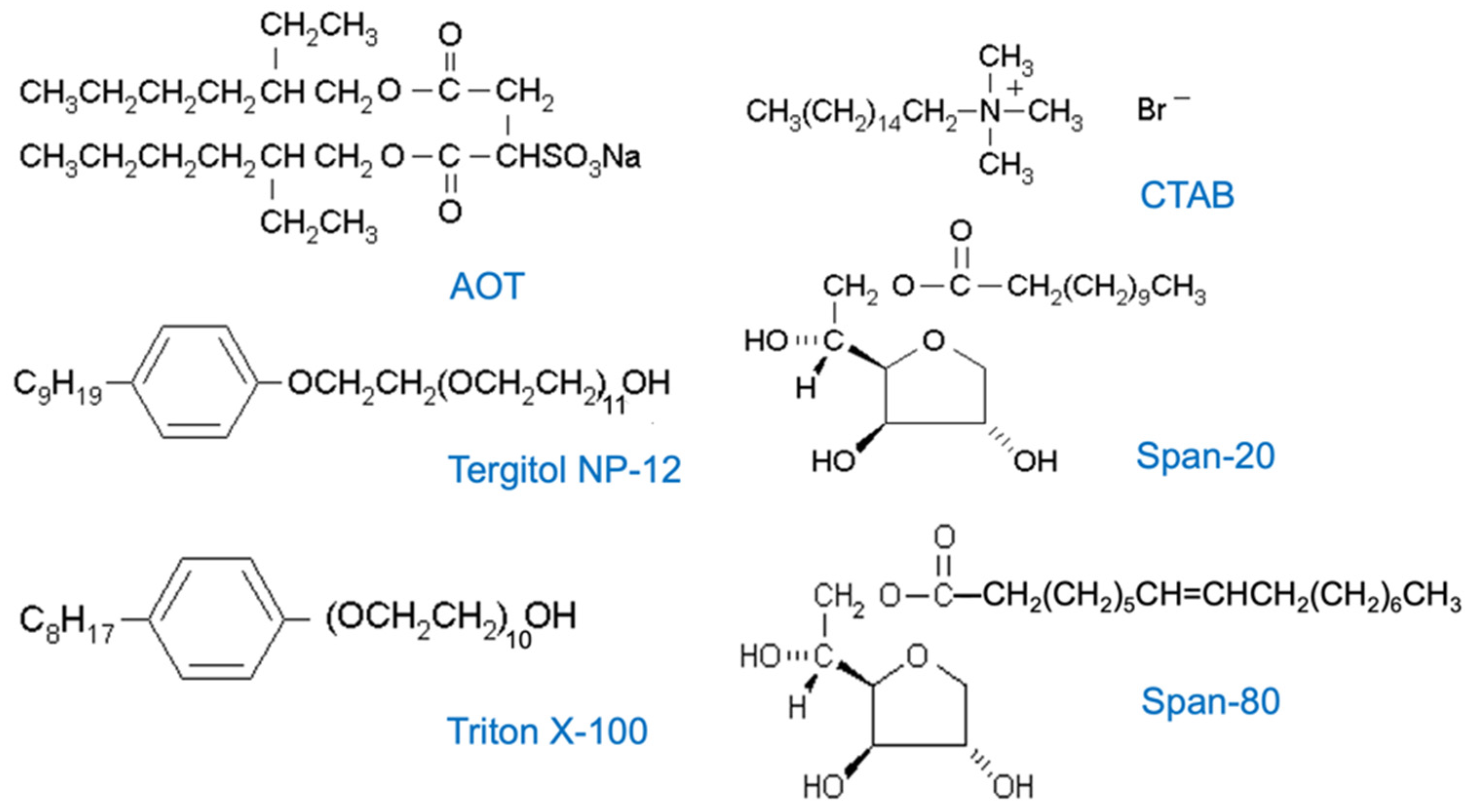
2.1. Chemicals and Materials

For the development of surface-patterned PS films, deionized (DI) water was prepared with a Mili-Q water purification system. Polystyrene beads (PS, MW~280,000, Fisher, Waltham, MA, USA), sodium dioctyl sulfosuccinate (AOT, ≥98% Fluka, Buchs, Switzerland), n-Hexadecyl trimethyl ammonium bromide (CTAB, ≥98%, Fluka), sorbitane monooleate (Span-80, ≥98%, Fluka), sorbitane monolaurate (Span-20, ≥98%, Fluka), t-Octylphenoxy polyethoxyethanol (Triton X-100, ≥98%, Fluka), nonylphenol ethoxylate (Tergitol NP-12, ≥98%, Fluka), and chloroform (≥98%, Fisher) were used as received without further purification.
For crystallization, electroless nickel plating, and electroless copper nanoparticle implantation within the surface pattern of PS film, acrylamide (≥96%, Merck, Rahway, NJ, USA), DL-malic acid (≥97%, Fluka), nickel (II) sulfate·6H2O (99–102%, Fisher), lactic acid (AR, 89.93%, Fisher), sodium hypophosphite monohydrate (97+%, Fisher), sodium chloride (≥99%, Fisher), hydrochloric acid (HCl) (AR-grade, fuming 37%, Merck), palladium (II) chloride (59% Pd, Merck), ammonia solution (25%, AR-grade, Merck), stannous chloride (99%, Merck), lead (II) acetate·3H2O (>99%, Merck), sodium acetate (≥99%, Merck), copper (II) sulfate·5H2O (≥95%, Merck), 4-vinyl pyridine (4VPy, ≥98%, Merck), and an aqueous solution of hydrazine hydrate (85%, Merck) were used as received without further purification.

2.2. Preparation of Patterned PS Films through Emulsion Coating

In the preparation steps detailed below, the glassware underwent multiple rinses with DI water, followed by drying with nitrogen blowing. The organic phase of w/o emulsion was formulated by combining 0.5 g of PS and a specific dose of an individual surfactant with 10 mL of chloroform in a 30 mL glass vial at 25 °C (ca. 3.2 wt.% of PS). The vial, capped securely, underwent rotary shaking to ensure thorough mixing. The resulting solution was left overnight at room temperature to achieve thermodynamically stable chain conformations in the solvent. Then, 10 µL water was introduced into the prepared solution, initiating emulsification using a vortex mixer (Heidolph REAX Control, Schwabach, Germany) set to 1000 rpm for 30 min. This process yielded a stable w/o emulsion, with the dispersed phase (water) constituting 0.1% of the total volume.
Subsequently, 0.1 mL of the emulsion was carefully transferred to the center of a clean glass slide (22 × 22 mm2), followed by securing the slide tightly onto the vacuum chuck within a spin-coater (CEE Cost Effective Equipment, Model 1000, Singapore). The spin rate applied was 800 rpm for 2 min. The emulsion-coated substrate was then dried for 1 h at 60 °C under vacuum conditions (5~10 torr) to eliminate chloroform, resulting in a PS film. The films from various emulsions were stored in a desiccator. According to AFM measurement, the films exhibited a thickness of approximately in the range between 150 and 200 nm. Regarding the sample naming, we designate the samples by the % w/w of the surfactant in the coating PS film. For example, when 3.4 mg Span 80 was incorporated in 0.5 g PS through the procedure described above, the surfactant content in the PS film is 0.67% by weight. The resulting PS film is dubbed PS_Span80_0.67. Likewise, PS_AOT_x and PS_CTAB_y follow a similar format.

2.3. Crystallization of Acrylamide in the Hydrophilic Bowl-Shaped Holes over the PS Coating Film

An acrylamide aqueous solution (30 wt.%, 100 mL) was prepared and filtered through a 0.1-micron MCE membrane filter (Millipore Sigma, Burlington, MA, USA) to remove insoluble tiny particles before use. A piece of PS_Span-80_0.67 film was then immersed in the aqueous solution in a 100 mL beaker, and this immersion system was ultrasonicated (Elma Ultrasonic Bath, Model T1040H, Singen, Germany) at a vibration amplitude of 40% for about 30 s. After that, the film was taken out of the solution and allowed to air drying at ambient temperature for 2 h. Then, the film was subjected to vacuum (~30 torr) annealing at 60 °C (Fisher, Model 281 Vacuum Oven) for 1 h to conduct crystallization. The resulting PS film is dubbed as PS_Span-80_0.67_AM30, where AM30 stands for the use of a 30% AM solution to carry out the recrystallization on the selected PS film. The control sample was prepared by introducing 10 mL of the above AM solution into a 50 mL petri dish, which was followed by the same air-drying and vacuum-drying steps, in which the 10 mL stock solution was totally dried up. The acrylamide crystallites grown in the bowl-shaped holes were then investigated by microscopic and X-ray diffraction methods.

2.4. Growth of Nickel Micro-Needles in the Hydrophilic Bowl-Shaped Holes over the PS Coating Film Using an Electroless Nickel (EN) Plating Technique

2.4.1. Preparation of a Sensitization and Activation Solution

This solution was prepared by adding PdCl2 (0.5 g) and SnCl2 (12 g) into a hydrochloric acid solution (10 mL, 1 M). Then, this solution was transferred into a NaCl aqueous solution (500 mL, 5.14 M). Subsequently, the resulting Pd metal colloidal dispersion was diluted by adding DI water until the total volume reached 1 L. The dispersion was finally subjected to aging by heating at 40–50 °C for 2 h with constant mechanical stirring.

2.4.2. Formulation of Acidic Hypophosphite EN Plating Solution

Nickel (II) sulfate·6H2O (22.4 g), lactic acid (21 mg), dl-malic acid (4 g), lead (II) acetate·3H2O (2 mg), and sodium acetate (8.5 g) were dissolved one-by-one in 200 mL of deionized (DI) water under magnetic stirring. Separately, sodium hypophosphite (25 g) was dissolved in 100 mL of DI water. The two solutions were then combined in a 1 L beaker, and the resulting mixture was diluted to 1 L with DI water. The pH of the final solution was adjusted to 4.8 using a few drops of ammonia solution.

2.4.3. The EN Plating Protocol

i.
A PS_Span80_0.67 film (2.2 × 2.2 cm2) was sensitized and activated by dipping it in the activation solution for about 3 min. The film was then rinsed with DI water and dipped in the 1 M HCl solution for about 30 s to remove Sn4+ generated from the sensitization and activation treatment. Subsequently, the film was rinsed with DI water and left to dry in a ventilation hood to obtain an activated PS film for EN.
ii.
In the subsequent plating step, 50 mL of the EN plating solution was first transferred to an 80 mL crystallizing dish placed in a water bath and warmed to 89 ± 1° under magnetic stirring. The activated PS film was then immersed in the EN solution for a duration ranging from 30 to 120 s to conduct the plating. After plating, the film was rinsed with DI water, air-dried, and further dried in a vacuum oven for about 1 h. Finally, the Ni-P-deposited film, named the PS-SP80_0.67-Ni30 film, was achieved, where 30 stands for a duration of 30 s of this plating step.

2.5. The Deposition of Copper Nanoparticles in the PS Film

This copper deposition process was initiated by incorporating an aqueous solution of CuSO₄/4VPy and hydrazine as the dispersed phase instead of water to form a w/o emulsion. Typically, 0.7 mL of an aqueous solution containing CuSO₄ (0.7 mmol) and 4VPy (2.8 mmol) was slowly introduced using a syringe into the chloroform solution containing PS and Span-80, as described in Section 2.2, while vigorously vortex mixing (1000 rpm) for 15 min to achieve a uniform w/o emulsion. A complex, namely Cu(4PV)2SO4, together with the free 4VP ligand, was, therefore, present in the dispersed phase (12 vol.%) in the w/o emulsion. After this emulsification step, 0.7 mL of hydrazine (54.4 wt.%) was injected into the emulsion while maintaining the vortex mixing for another 15 min at ambient temperature (~25 °C). The dispersed phase had a volume fraction of approximately 13 vol%. The emulsion coating and subsequent post-drying were performed following the same procedure mentioned in Section 2.2. During this interval, the emulsion color changed from blue to dark brown, and the darkness increased with time due to the formation of Cu metal colloids. The resulting film is referred to as PS_SP-80_0.67_Cu0.7_w or w/o, where 0.7 is the dosage (in mmol) of copper complex participating in the reduction reaction and w indicates the use of 4VPy, while w/o indicates the absence of 4VPy. In addition to these two films, another film was fabricated using a different protocol, which involved conducting the reduction after drying the emulsion coating containing a complex made with only 14 mmol of 4VPy. The reduction step was executed by dipping the dry film in the same hydrazine solution for 1 h at 25 °C. The resulting film is dubbed PS_SP-80_0.67_Cu0.7_ w/rd, where rd stands for the reduction of the dry film.

2.6. Structural Characterizations

2.6.1. Molecular Weight of PS and Its Viscosity in Chloroform

The weight average molecular weight (Mw) of PS was confirmed to be 282, 800 g/mol using gel permeation chromatography (GPC-SEC analysis SERIES 1000 MSD) with a chloroform solution of PS (0.17 mM or 3.2 w/w %). This solution was employed to form the continuous phase of the w/o due to its suitable viscosity of 22 cp (centipoises) at 25 °C, measured with a viscometer (the Brookfield Starch Viscosity Measuring System Model SSB). Each measurement was repeated five times, and the average value was taken.

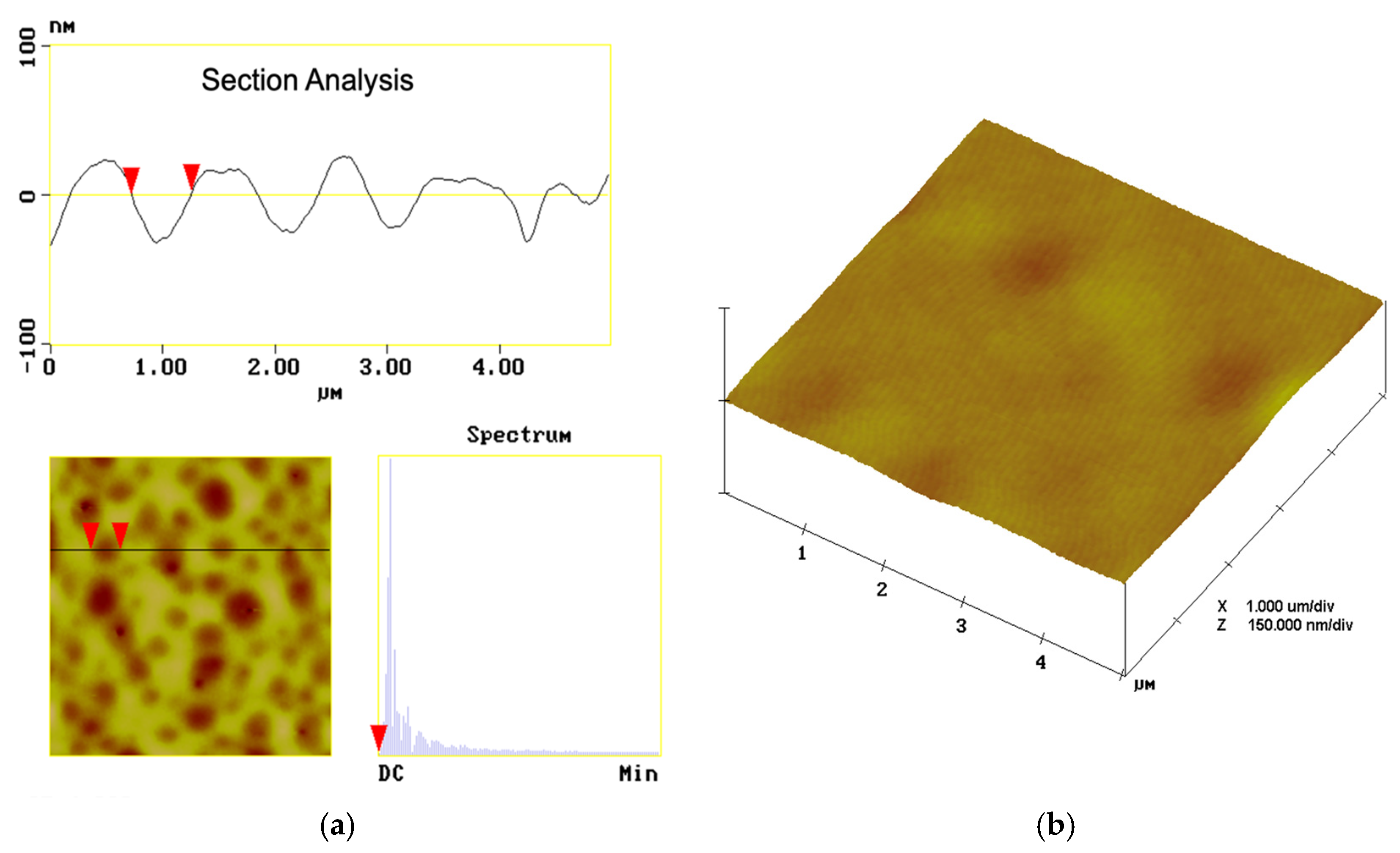
2.6.2. Uncovering the Surface Pattern Using Atomic Force Microscopy (AFM)

The 3D topographic images of the polymer films were measured using an atomic force microscopy (Digital Instruments Nanoscope IIIA, Plainview, NY, USA) instrument, selecting the tapping mode with an amplitude frequency of 300 kHz at room temperature. A 3 μm scanner and commercially etched silicon tips were employed during morphology evaluations. The mean constant of the tips was 21–78 Nm−1, the length was 120–130 μm, and the tip ends were about 10 nm in diameter. To allow the thin PS film to be examined under AFM, the samples were attached to the holder with double-sided tape. Additionally, to avoid possible tips artifacts, each experiment was repeated with different tips.

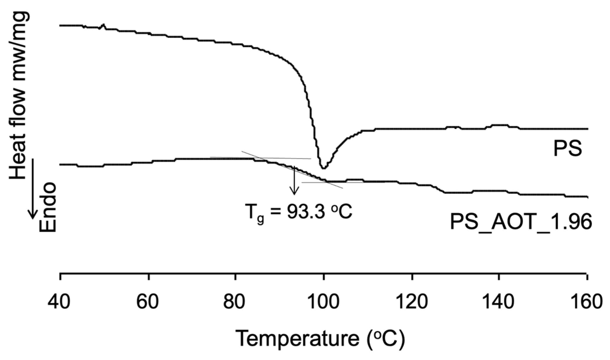
2.6.3. Examination of the Impact of a Surfactant on the Phase Structure of a Patterned PS Film Using Differential Scanning Calorimetry (DSC)

The surfactant present in a patterned PS film is expected to influence the packing state of the PS chains. This was examined using a differential scanning calorimetry (DSC) instrument (Mettler Toledo Star DSC-821) with a scanning rate of 10 °C/min. A small amount of the polymer sample (10 mg) was first weighed and sealed in an aluminum crucible. The DSC scan was conducted under a nitrogen flow. Each sample was subjected to a scan starting from 25 °C to 150 °C and then back down to the starting point at a heating rate of 10 °C/min to remove the thermal history of the sample. The DSC diagram was recorded in the subsequent scan from 25 °C to 250 °C using the same heating rate.

2.6.4. Recording the Surface Morphology Images and Compositions of the Patterned/Deposited PS Films by Scanning Electron Microscopy (SEM)

The images of the surface micro-structures of the resulting PS films (40 s at 40 A) were investigated with a scanning electron microscope (SEM, JEOL JSM-5600, Tokyo, Japan). The samples were sputter-coated with Pt before scanning. The surface compositions of the electroless-metal-deposited PS films were determined using energy dispersive X-ray (EDX) analysis. The characterization was performed using an EDX detector incorporated into the SEM chamber, enabling quick surveys and spatial mapping of individual elements.

2.6.5. Observing Cu Nanoparticles Embedded in PS Film with Transmission Electron Microscopy (TEM)

A trace amount of the sample (approximately 50 mg), such as PS_SP-80_0.67_Cu0.7_w, was dissolved in 3 mL of chloroform in a glass vial. The vial was immersed in an ultrasonic processor (Elma Ultrasonic Bath, Model T1040H) at a vibration amplitude of 40% for 15 min to completely dissolve the sample. A drop of solution was transferred onto a copper grid (300 mesh) covered with a continuous graphite film and air-dried. The sample was subsequently examined with a TEM unit (JEOL JEM-2010).

2.6.6. Examination of the Adsorption of the Embedded Nano-Copper Particles Using Ultraviolet–Visible (UV–VIS) Spectroscopy

The PS films containing embedded Cu nanoparticles were scanned using a UV–Vis spectrophotometer (UV–Vis 3101 PC, Shimadzu, Kyoto, Japan). The sample was placed vertically on a UV cuvette surface with a 1 cm pathlength, secured with double-sided tape. The scanning range spanned wavelengths from 300 to 800 nm. For each scan, the background was first zeroed to ensure accurate measurements.

2.6.7. Determination of the Structures of the Crystallites Growing on or within the PS Films by X-ray Diffraction (XRD) Analysis

The PS films loaded with the recrystallized acrylamide (AM), Ni-P alloy needles, or Cu nanoparticles (NP) were examined by XRD analysis on a diffractometer (SHIMADZU XRD-6000) using a Cu-Kα radiation source (λ = 1.54 Å). The analysis details are as follows. Cu NP-embedded films: The diffractograms were recorded using a scan step size of 0.020° and a scan speed of 2 deg./min over a 2-theta angle from 25 to 80 degrees. Ni-P-deposited PS films: The diffractograms were recorded using a scan step size of 0.020° and a scan speed of 2 deg./min over a 2-theta angle from 35 to 80 degrees. AM crystallite-grown PS films: The diffractograms were recorded using a scan step size of 0.020° and a scan speed of 2 deg./min over a 2-theta angle from 10 to 40 degrees.

3. Results and Discussion

3.1. Influences of the Nature of the Surfactant on the Pattern Development over the Coating and Drying Course

3.1.1. The Impact of Cationic Surfactant (CTAB)

Drying a w/o emulsion coating laid on a glass slide microscopically involves interactions between chloroform-swelled PS chains and the surfactant occurring around the edge of each dispersed water droplets, which in total occupies 0.1% of the volume. In contrast, for the control sample, the PS–chloroform solution coating, drying involves the contraction of PS chains occurring without interference while the solvent vaporizes. Hence, a pristine PS film was obtained after drying. The first patterned PS film to manifest the surfactant effect is PS_CTAB_0.67, which presents a close array of the bowl-shaped holes over the surface of the film (Figure 2a). Based on this SEM image, the average surface hole width is 2.7 μm, with a standard deviation of 0.4 μm. The surface hole density is 0.11 holes per square micron meter (0.11/μm2). This particular surface pattern was further verified using AFM section analysis (Figure 3a). The diagram shows periodic concave shapes, i.e., holes, with the depth of an arbitrarily selected hole being about 30 nm (below the horizontal line, at 0 of the vertical axis) and a relatively wide span (diameter) of 2 μm. In contrast, there are no holes, except random wrinkles resulting from the vaporization of chloroform from the swollen PS tangles in vacuum, present on the control sample (2b). Its 3D AFM image also shows a patternless surface (Figure 3b).
Regarding the impact of surfactant content (wt.%) in the PS film on the surface pattern, as expected, increasing the dose of CTAB causes the holes to gradually shrink in size. When the wt.% reaches 1.33 (Table 2), all holes start merging along their edges, resulting in holes that no longer possess complete circular boundaries. This phenomenon can be interpreted as the instability of the w/o emulsion generated, possibly due to the formation of CTAB aggregations, i.e., micelles, in the water phase because of its untrivial water solubility (Figure 2d). This occurred when the excess of CTAB could no longer be absorbed by the chloroform–PS solution. Logically, these micelles would disrupt the CTAB array at the interface through the adsorbing and partitioning actions. The leverage of increasing the concentration of emulsifier on the stability of an emulsion has been reported [31]. During the drying of the w/o emulsion coating, the dispersed water droplets migrate to and merge at the vaporization surface [32]. It is noteworthy, however, that the average diameter of the holes is far greater than that of the dispersed water droplets in the emulsion. The mean droplet size of an emulsion depends on the agitation and the volume fraction [33,34]. Thus, the present w/o emulsion must have sub-micron water droplets due to the substantially low volume fraction of the dispersed phase, approximately 0.1 vol.%, and a medium agitation rate. Therefore, the larger surface hole sizes observed on the dry films compared to the sizes of water droplets were attributed to two factors: the contraction of the PS–chloroform gel surrounding the water droplets during drying, and the combination of the dispersed droplets. It could be perceived as a non-unform drying process.
Regarding the interaction between CTAB and PS, this happens at the surface and in the bulk matrix of PS, since the dry PS film thickness (~150 nm according to AFM image) is much larger than the molecular length of CTAB (ca. 3 nm). The hydrophobic cetyl tails (16 carbon aliphatic chain) of CTAB insert themselves into PS chains over the patterned surface and within the bulk of the PS film in the form of reverse micelles, similar to portrayed in Figure 2c. This occurs after drying, which removes CHCl3 and H2O, as aforementioned. The cetyl tails act as lubricants, reducing the association of the PS chains and facilitating the segment motion of PS chains. This effect significantly weakens the glass transition barrier. As shown in Figure 4, a feeble Tg step appears in the range centered around 60 °C. The PS_film, used as the control, shows a Tg very close to that unaffected by surface effect. Additionally, an explicit endothermic peak is exhibited at 103.6 °C. This peak, originating from the first-order phase transition, is attributed to the thawing of the array of quaternary onium (N+R4) groups of CTAB. Such an array of the N+R4 heads happens on the surface of the bowl-shaped holes as well as inside the PS film bulk, where the reverse CTAB aggregates exist. The N+R4 array layer involves a combinatory interfacial structure, including the hydrophobic association between cetyl tails and PS chains, as well as the ionic association of quaternary ammonium groups [35]. This explains why the thawing temperature is far below the melting point of CTAB. It was also observed that when CTAB adsorbs on PS latex particles, forming a surface composite layer with a similar CTAB content to the present case, CTAB undergoes order–disorder melting of its tails at 104 °C [36]. Nevertheless, we believe that the ionic association of the cation groups is responsible for the observed thawing peak in the present study. This is because the majority of CTAB molecules migrate to the water/oil interface with their tails inserted into the PS chains, as illustrated in Figure 2d, while the emulsion forms.

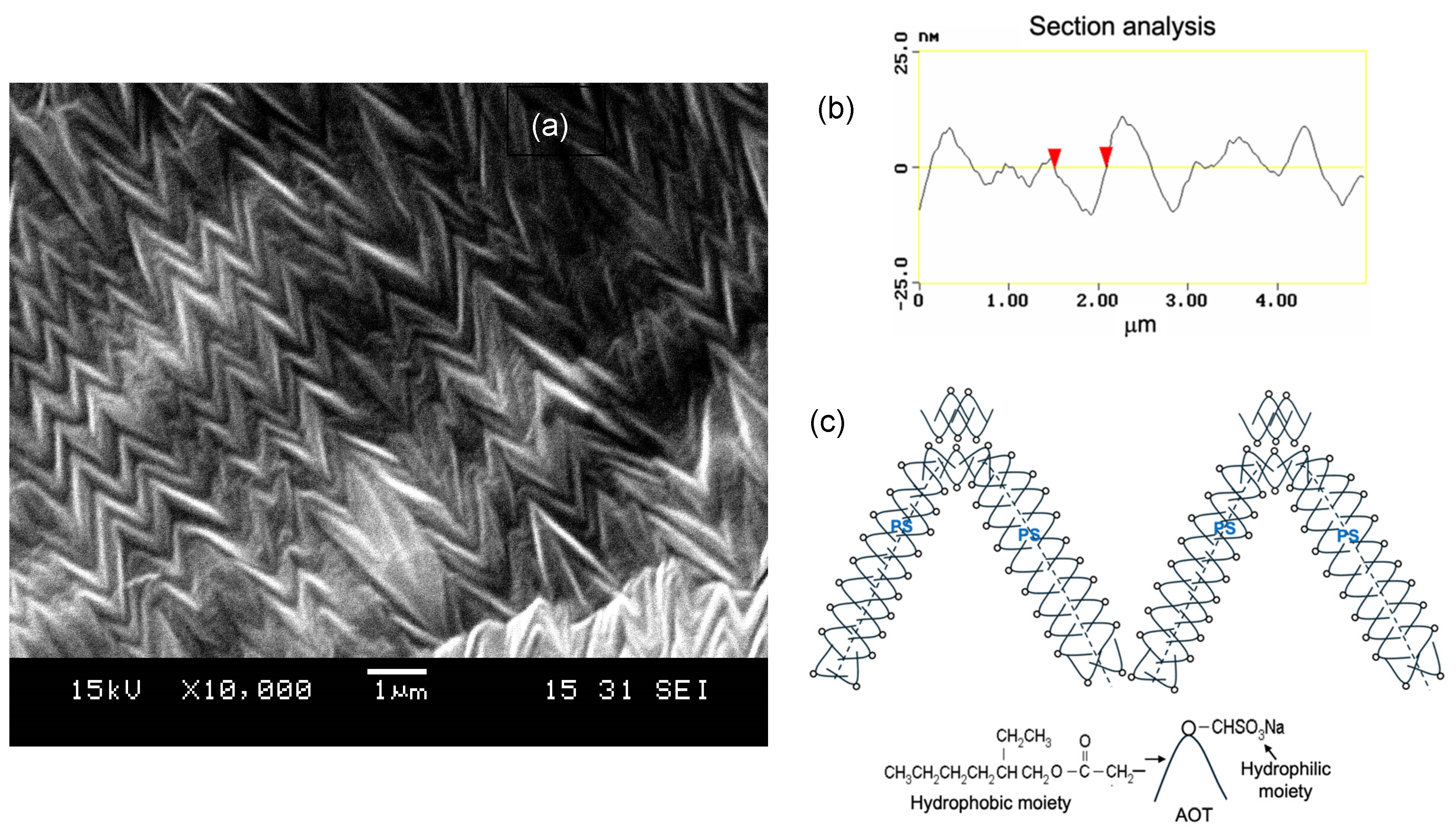
3.1.2. The Impact of Anionic Surfactant (AOT)

Compared to CTAB, AOT has a comparable HLB value but far lower water solubility, and, hence, it is well known to stabilize the reverse microemulsion of water in isooctane [37]. Its dual hydrophobic chains allow AOT molecules to form stable reverse micelles. In this study, the reverse emulsion structures stabilized by AOT are transformed into two kinds of surface patterns on the PS film. When the AOT content in PS ranges from 0.032% to 0.66%, we observed a surface pattern similar to Figure 2a, with smaller holes forming as the AOT content increases within this range. However, the PS film surface morphology exhibits an M-shape pattern (Figure 5a) when the AOT content ranges from 1.34% to 2.64%, with the most distinct pattern being observed at 1.96% AOT. The higher water solubility of CTAB restricts its patterning capability in the higher content range because of the reason given in the above section.
The transition of the surface pattern from bowl-shaped to M-shaped can be attributed to the change in the dispersed phase geometry from droplets to strips. Water strips form in the continuous ditch between the assembled M-shaped units, each consisting of aligned hydrophilic heads along the edges of the four lines of each M-shaped unit, as illustrated in Figure 5c. This change reflects the thermodynamic tendency due to the presence of a higher concentration of AOT, leading to the reassociation of AOT with PS during the drying of the emulsion coating. The AFM section analysis exhibits a mountain–valley-like surface profile (Figure 5b), characterized by a low RMS roughness (Table 3) that corresponds well with the SEM image. Specifically, the mountains represent the cross-section of the four lines of the M-shaped units, and the valleys are the ditches left behind as the water vaporizes. The section analysis diagram shows that the selected valley has an upper width of about 0.5 μm and a depth (below the horizontal line) of approximately 10 nm. Furthermore, the PS_AOT_1.96 film exhibits a shallow glass transition step (between the two tangent line cross points) at a lower temperature than the pure PS film. This suggests that the AOT molecules are left behind in the PS film bulk matrix, in the form of reverse micelle, after drying, as elucidated above. However, unlike CTAB, the interfacial array of AOT does not result in ionic bonding among its sulfonate anions over the surface, and, thus, no thawing peak appears (Figure 6). A previous study scrutinizing the AOT stratification on the latex blend film formed from coagulated PS and poly(n-butyl acrylate) latexes also showed an insignificant association of AOT molecules at the film–air interface and found that AOT molecules increase the free volume of PS, leading to a downward shift in its Tg [38].

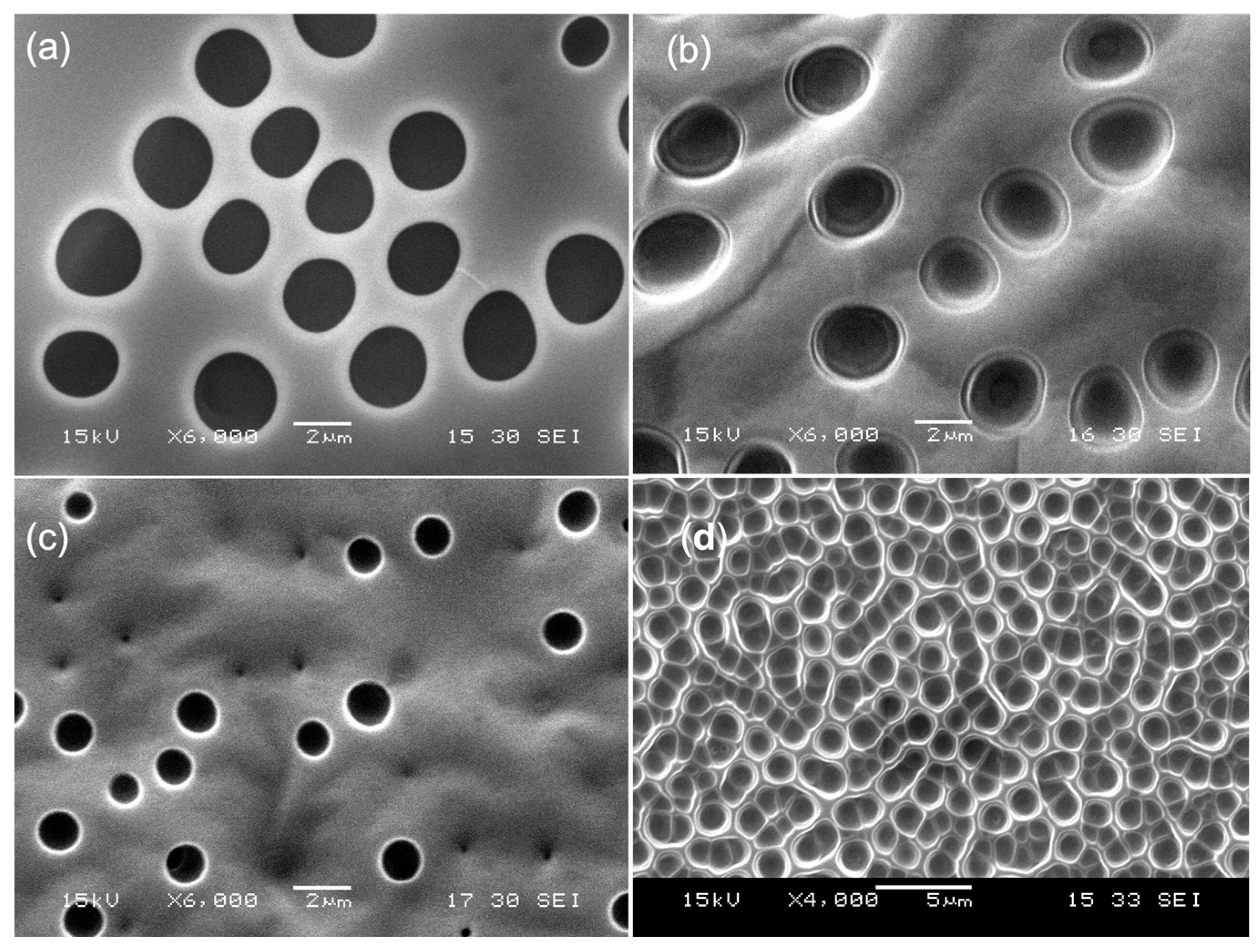
3.1.3. The Impact of Non-Ionic Surfactants

As listed in Table 1 and Figure 1, the four selected non-ionic surfactants show the following hydrophilic order according to their HLB values: Tergitol ≥ Triton > Span-20 > Span-80. Both Tergitol and Triton rely on the long hydrophilic moiety, consisting of ethylene glycol units to sustain full water solubility. As a result, a certain portion of either Tergitol or Triton surfactant, depending on the dose added, will enter the dispersed phase in the form of micelles during the course of emulsion formation. This would certainly influence the development of the surface pattern because more surfactant molecules are consumed in the water phase to generate the holes. The resulting PS films (Figure 7a,b) reflect this effect, yielding a relatively lower number of pores per area but with a larger pore width. However, once the surfactant content exceeds a certain value, the holes begin to merge to some extent due to an unstable w/o interface, as elaborated upon in Section 3.1.1. Furthermore, regarding the weight fraction range of these two surfactants causing pattern formation, Tergitol-12 ranges from 0.07% to 0.54%, whereas Triton-100 ranges from 0.07% to 1.96%.
Moreover, the DSC analysis of both PS_Tergitol_0.07 and PS_Triton_1.96 shows that, compared to the Tg of PS at 96.8 °C, the glass transition temperatures of PS in both films are significantly lowered to 64.8 °C and 66.1 °C, respectively (Figure 8). This downward shift in the glass transition suggests that either surfactant is incompatible with the PS matrix, inducing the generation of free volumes between surfactant molecules and PS chains. The repulsion effect is considered to be caused by the hydrophilic ethoxy segments. Compared to PS_Triton_1.96, despite a much smaller content in the PS film, PS_Tergitol_0.07 presents a similar glass transition step at a slightly lower temperature. Since both surfactants have similar molecular structures and, hence, possess almost the same HLB and water-solubility values (Table 1), it is rational that both films retain similar contents of the two surfactants in their bulk. The excess surfactant molecules, particularly for Triton, would migrate to the dispersed phase during the emulsification and subsequent drying process. This claim could be supported by the AFM section analysis (Supplementary Figure S1) that records the depths of any selected hole: 36 nm from PS_Tergitol_0.07, and 26 nm from PS_Triton_1.96. The surfactant deposition is responsible for the shallow surface holes of the latter. This inference is in agreement with the RMS difference between these two films (Table 3). Following the same logic, PS_Span-20_0.07 presents a stronger glass transition step at a higher temperature than the above two films, signifying the better compatibility of Span-20 with PS. This is because Span-20 has a shorter hydrophilic segment and a longer aliphatic chain than Tergitol and Triton. The effective weight fraction range of Span-20 to form the surface pattern with discrete holes is from 0.07% to 0.63%. It is considered that a medium HLB level and low water solubility make the surfactant tend to reside in the PS matrix along the interfacial boundaries. Consequently, PS_Span-20_0.07 exhibits a set of holes with diameters ranging approximately from 0.2 to 1.4 µm (Figure 7c), whereas the small holes never occur in the other two patterned PS films in Figure 7, demonstrating the stronger emulsion stabilization capability of the surfactant. Correspondingly, a randomly selected surface hole shows a depth of 38 nm and a width of 0.54 µm (Supplementary Figure S2). This hole is deeper than in the other films discussed above, indicating the surfactant’s interfacial stability based on such a low content.
Furthermore, Span-80, having the lowest HLB value among the surfactants discussed above, stimulates a surface with a honeycomb pattern (Figure 7d), indicating a significant increase in surface area contributed by the inner surface of the holes. This outcome is tied to the dominant hydrophobic trait of Span-80, supported by its long oleate chain. Due to this unbalanced molecular structure, Span-80 demonstrates considerable potential to stabilize the dispersed phase within the w/o emulsion. The effective weight fraction of Span-80 to induce the surface pattern ranges from 0.34% to 1.96%. Of the films obtained, PS_Span-80_0.67, exhibits the most densely packed holes on its surface according to SEM image. Based on this SEM image, the average surface hole width is 1.3 μm, with a standard deviation of 0.07 μm. The surface hole density is 0.34 holes per square micron meter (0.34/μm2). It is clear that PS_Span-80_0.67 has a greater surface hole density than PS_CTAB_0.67. The 3D configuration of the surface pattern of this film was also recorded (Figure 9a); the depth of the holes according to the section analysis shows a distribution from 16 to 65 nm, with a median depth of 32 nm, an RMS roughness of 21.7 nm, and a median hole width (similar to the chord) of about 0.6 µm (Figure 9b). Except for the special surface pattern, the DSC analysis found that in addition to the reduction in the Tg of PS, another glass transition step appears at a temperature significantly higher than that of pure PS. This occurs even with the use of the lowest surfactant content, i.e., in PS_Span-80_0.34, where the second Tg step appears at 130.4 °C (Figure 9c). This can be attributed to the thawing of the associated hydrophilic heads (sorbitan) involving hydrogen bonding among them to form a particular cluster. Similar to the PS_CTAB films, the association of hydrophilic heads occurs over the honeycomb surface and inside the reverse aggregates in the PS bulk. It is noteworthy that this hydrophilic head association never happens in pure Span-80 except in this specific microenvironment. This is because the insertion of the hydrophobic oleate tails into the PS matrix facilitates and enhances the association. As the Span-80 content increases to 0.67% and then to 1.33%, the second Tg step shifts to a higher temperature (ca. 144 °C) while the first Tg step lowers to as low as 76.3 °C due to the same logic. Furthermore, once the Span-80 content exceeds the upper bound to 1.96%, a significantly larger second Tg step appears, despite this content no longer exhibiting the pattern.

3.1.4. A Qualitative Assessment of Polystyrene–Surfactant Interactions and the Surface Properties of the Patterned Films

As highlighted above, HLB is critical in determining the surface pattern eventually generated on the PS film. HLB has been correlated with the solubility parameter (δ) of a surfactant [39], as both properties are rooted in the molecular structure of the surfactant. As a property of solution thermodynamics, the parameter δo of a molecule evaluates its compatibility with another molecule in both liquid and solid states. δo is expressed through three intermolecular interaction components, known as Hansen solubility parameters [40], as shown in Equation (1). These components are δD (London dispersion), δP (polar interactions), and δH (hydrogen-bonding interactions), which together characterize the inter-molecular or -moiety’s interactions.
δ o = δ D 2 + δ P 2 + δ H 2
It is important to note that the previous discussion has interpreted the interactions between a surfactant and PS, primarily involving the surfactant’s tail and PS chains proximate to the interface within the film. Therefore, the solubility parameter of the tail (δtail), rather than that of the entire molecule (δsurf), is essential for this analysis. For each surfactant, its δtail value can be determined using the group-contribution method (Equations (2)–(4)). The numerical values obtained are listed in Table 4, where the tails contribute significantly to the solubility parameters of their respective surfactants (δsurf). Moreover, it is important to note that δD plays the dominant role in δtail. Equations (2)–(4) are as follows:
δ D = i n i C i + 17.3231 ,
δ P = i n i C i + 7.3548 ,
δ H = i n i C i + 7.9793
where Ci is the contribution of the first-order group of type i that appears ni times in the tail.
Similarly, London dispersion forces are predominant in PS due to its non-polar chain structure, with a solubility parameter (δPS) of 18.4 (MPa)0.5 and a δD of 18.1 (MPa)0.5 [43]. Thermodynamically, the closer the solubility parameters of the two molecules, the more compatible they are for forming a blend. Thus, among the nonionic surfactants listed in Table 4, Span-80 exhibits the best compatibility with PS. Although, Span-20 has a δtail close to that of Span-80, its higher δsurf indicates a stronger hydrophilic effect. Consequently, Span-80 is more effective in influencing the surface roughness of the PS film. This is because its migration to the interface during the drying step encourages the PS chains to move towards the surface due to London dispersion interactions. Among the ionic surfactants, AOT is the most incompatible with PS, resulting in the smoothest surface pattern. In contrast, CTAB engenders a surface pattern similar to Span-80, but its ionic clustering at the interface counteracts the London dispersion effect, leading to an RMS comparable to that of Span-20.
As for the surface properties, focusing on the water contact angle (CA) and water contact angle hysteresis (CAH), although this study has yet to experimentally measure these two properties, the effects of the attained PS film surfaces on these two properties can still be assessed by applying existing knowledge, such as in a recent short review [44]. The patterned PS film surfaces possess a hydrophilic Wenzel state because they are fully water wettable. The water CA should be significantly smaller than 90°, depending on the surface embedment density of hydrophilic heads and their types, with ionic (AOT and CTAB) being stronger than non-ionic. In addition, the CA will decrease with an increase in roughness. More specifically, these surfaces should exhibit large hysteresis, as the holes and roughness will drag the receding contact line, leading to very small receding angles.

3.2. Utilization of Honeycomb Holes on the PS_Span-80_0.67 Film to Grow Pure Acrylamide Crystallite

Investigation of whether the micro-holes on this w/o emulsion-cast PS film influence the crystallite growth of acrylamide (AM), selected as a testing compound, involves the structural characteristics of these micro-holes: i. a concave surface that allows hydrogen bonding; ii. a ratio of median hole depth to width (~30/600 in nm) suitable for accommodating crystallites grown from the solution recrystallization process (Section 2.3). In comparison, two previous studies differ in their substrate surface structures, lacking hydrophilic groups and honeycomb-like features: i. deposition of Fe2(HPO4)3 on porous PS beads (160 µm) with a mean pore size of 0.1 nm [45]; ii. deposition of ZnO film on a polyethylene terephthalate (PET) sheet [46].
Compared with the pre-deposited surface morphology shown in Figure 7d and Figure 9a, the PS_Span-80_0.67_AM30 film (Figure 10) displays noticeably thicker hole peripheries and shallower hole interiors. The AFM 3D contour of this film is significantly less rough, with an RMS of 1.0 nm compared to the RMS of 21.7 nm prior to recrystallization. Furthermore, the AFM section analysis (Supplementary Figure S3) shows an average hole depth of approximately 10 nm, which is significantly shallower than the depth before crystallization. Additionally, the IR spectroscopic characteristics of the AM crystallites, specifically the C=O and NH2 stretching bands, were identified against the IR fingerprints of PS (Supplementary Figure S4).
The crystalline structure of AM crystallites on PS_Span-80_0.67_AM30 (Figure 11) displays a pattern consisting of three peaks at 2-theta angles of 11.38°, 19.48°, and 28.78°. Moreover, these three peaks present an intensity proportion of 100:25:25. These diffraction data match those defining the monoclinic acrylamide crystal (Ref: No. 11-0920, 2001 JCPDS-International Centre for Diffraction Data). In contrast, the first control sample, the blank film PS_Span-80_0.67, displays an amorphous halo, and the second control sample, the AM powder obtained from the same recrystallization step, exhibits a similar XRD pattern. However, this XRD pattern differs from that of PS_Span-80_0.67_AM30 in two aspects: (i) the first peak has a slightly greater 2θ at 12.08°, signifying a compression of the d-spacing along the [001] direction, and (ii) the diffraction peaks are broader, signifying smaller crystallite grains. These subtle divergences in the crystalline structure of AM highlight the leverage of the unique surface characteristics (honeycomb holes and surface embedded hydrophilic groups) of PS_Span-80_0.67 on the seeding details of AM during the initial stage of the recrystallization process, enhancing the crystalline uniformity of AM. It is believed that the initial crystallization embryos form from hydrogen bonding between AM molecules and sorbitan groups embedded primarily on the concave hole surface. This interaction triggers a pseudo-epitaxial effect, with the hydrogen bonding likely aligning a layer of AM molecules over the concave hole surface, thus inducing subsequent crystallization. This effect was not observed when the concentration of the starting AM solution was 15% instead of 30%. As a result, the film PS_Span-80_0.67_AM15 does not exhibit an XRD pattern other than noise peaks (Supplementary Figure S5). This finding suggests that a concentration threshold is required to initiate the seeding of AM on the hole surface of the honeycomb film. The conclusion is drawn from the observation that the amount of either AM stock solution (15% or 30%) attached to the PS_Span-80_0.67 film before drying is relatively consistent.

3.3. Utilization of Honeycomb Holes on the PS_Span-80_0.67 Film to Grow Ni-P Alloy Micro-Needles

On the basis of the same notion, to conduct the recrystallization of AM on the PS_Span-80_0.67 film, we carried out EN plating to examine the morphology of the Ni-P alloy formed on the film. The EN plating is essentially an autocatalytic process [47], which starts with deploying Pd colloidal particles onto the substrate (Section 2.4.3-i) before the deposition of the Ni-P alloy. These Pd particles act as reactive sites to initiate the EN plating. Mechanistically, the microenvironment of Pd seeds affects the morphology of the subsequent EN plating layer. Figure 12a displays the surface image of the film after EN plating for a 60-second duration, in which a Pd-deployed PS film was dipped in the EN plating solution (Section 2.4.3-ii); the dipping duration corresponds, therefore, with the plating time. It reflects two distinct morphological characteristics: i. Ni-P needles grow inside discrete holes with diameters of 4–5 µm; ii. the holes are larger than those prior to plating and are no longer tangential to each other, as shown in Figure 7d.
It is proposed that the EN-plating-induced hole expansion and cramming mechanism causes this variation in surface morphology, involving two operational factors, namely the EN plating bath temperature (ca. 89 °C) being greater than the Tg of the PS in PS_Span-80_0.67, and the fact that the EN plating did not occur in parallel in each hole throughout the PS_Span-80_0.67 film surface. Consequently, once EN proceeds more rapidly in some holes, these holes expand more and more faster due to the EN’s autocatalytic nature, squeezing their neighboring holes, which is assisted by the softness of the PS matrix (in a rubbery state) at the plating temperature, leading to the sealing of these holes. This explanation is verified by the periphery domains of the survival holes in Figure 11, where the sign of the buried alloy needles right underneath the surface layer can be spotted. With the extension of the plating time to 120 s, Ni-P alloy dendrites prevailed over the substrate (Figure 12b). This dendritic morphology is unique compared to those plated on the non-patterned PS film and on a brass sheet used as the control, Brass_Ni30, (Supplementary Figure S6). Moreover, the EN plating rate on the brass sheet is faster than on either PS film. Moreover, continuous plating for over 120 s would result in the gradual loss of the dendritic morphology.
Regarding the XRD pattern of Ni-P alloy, it is commonly known [48,49] that the alloy possesses an fcc crystal lattice generating three main diffraction peaks, as listed in Table 5. The two Ni-P deposition layers on the two different PS films reveal these three diffraction planes. However, their (200) and (220) planes appear at apparently greater 2θ angles than the known corresponding diffraction data (Table 5 and Figure 13). These phenomena can be attributed to a higher phosphorous content in the alloy, causing lattice congestion along these two crystallographic directions, particularly in the [200] direction. The EDS analysis of both Ni-P on PS_Span-80_0.67_Ni120 and the brass sheet shows rather different phosphorous contents in the Ni-P alloy: the former has 36 wt.% (Supplementary Figure S7) while the latter has 12 wt.%. In addition, PS_Span-80_0.67_Ni120 displays more intense peaks than PS_Ni120, indicating the presence of better-ordered crystal lattices inside the dendrites. Moreover, compared to the references (in Table 5), PS_Span-80_0.67_Ni120 shows apparently narrower and sharper (200) and (220) peaks. This difference implies that the Ni-P dendrites comprise more orderly aligned fcc unit cells despite containing a higher P content. Briefly, the EN plating on the patterned PS film exhibits three unique structural characteristics: dendritic shape, high phosphorous content in Ni-P alloy, and a well-extended fcc crystal structure.

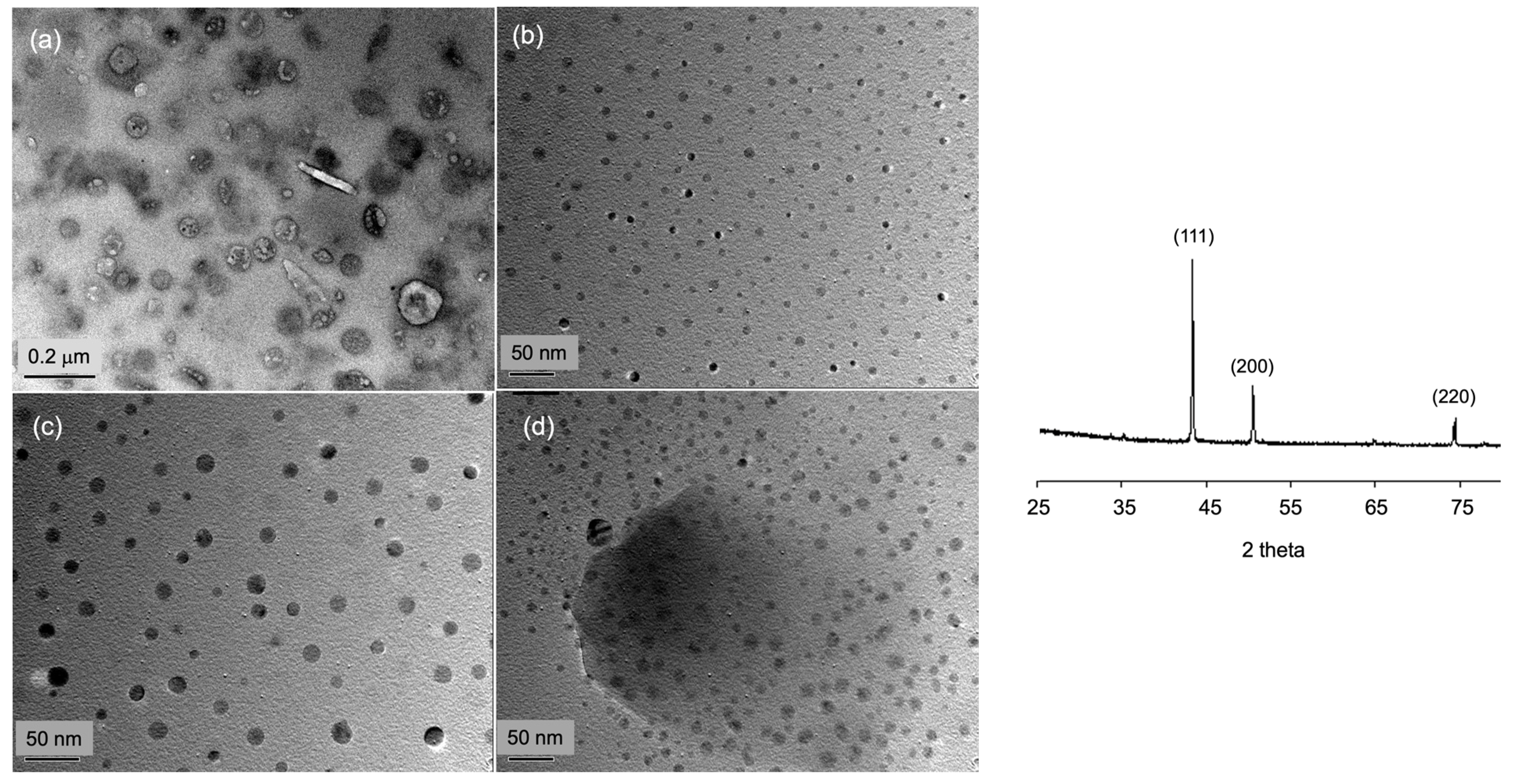
3.4. In Situ Growth of Copper Nanoparticles (NP) Inside the Dispersed Droplets during the Drying of the Cast w/o Emulsion

As proposed in the Introduction, the dispersed aqueous phase of w/o emulsion in droplet form can act as a microreactor for the reduction of the copper salt, CuSO4, or the complex Cu(4VPy)2SO2, both during the formation of emulsion and throughout the drying process of emulsion coating. This design confines the reduction reaction within each droplet. Three electroless copper trials were conducted using the conditions listed in Table 6. For the trials in the first two rows, employing 4VP as a ligand to form a coordination complex with Cu2+ ion is critical to ensure the stability of the emulsion and to smooth the reduction reaction [50]. In the first trial, 4VPy was absent, and the resulting PS_Span-80_0.67_Cu0.7_w/o film (Figure 14a) shows both rod- and sphere-shaped Cu NPs, embedded in the surface PS matrix, with a particle size distribution (PSD) ranging from 32 to 158 nm, of which 63 nm has the highest frequency (ca. 61%). This suggests that the CuSO4 salt dissolved in the dispersed phase increases the ionic strength and the surface tension, thereby undermining the stability of the interface despite the presence of Span-80 (Figure 14a). In contrast, converting the Cu2+ ion to the complex ion [Cu(4VPy)2]2+ by including 4VPy in the dispersed phase overcame this drawback in the second trial. The TEM image of the resulting PS_Span-80_0.67_Cu0.7_w film (Figure 14b) shows a uniform distribution of embedded spherical Cu NPs over the PS film, with two predominant particle sizes (frequency) of 9 nm (30%) and 16 nm (70%). It is believed that [Cu(4VPy)2]2+ ions attract water molecules more weakly than Cu2+ ions, causing a relatively lower osmotic pressure at the interface, thereby having a reduced impact on the Span-80 stabilized interface.
In the last trial, no hydrazine solution was introduced during either the preparation of the emulsion or the drying of the emulsion coating. The resulting film, PS_Span-80_0.67_Cu0.7_w/rd, displays a surface embedded with spherical Cu NPs (Figure 14c). These particles present three typical sizes: 10 (10%), 13 (40%) and 23 (50%). Compared with the second trial conducting in situ reduction, this trial results in a slight degree of coagulation of the dispersed droplets, particularly during the drying course. Furthermore, if Span-80 was omitted in the second trial, it resulted in a slightly broader Cu NP size distribution of 17 nm (81%), 33 nm (17%), and 50 nm (2%) (Figure 14d). This outcome signifies that the complex ion, Cu(4VPy)2SO4, may supply a certain degree of interfacial stability to defer the coagulation of the aqueous droplets before the formation of Cu NPs inside the droplets.
The PS-embedded Cu NPs in the four films all present a clear XRD pattern, well-fitting the fcc lattice (inset of Figure 14), and have 2-theta angles at 43.30°, 50.43°, and 74.13°, respectively. This observation proposes that the reduction inside tiny droplets still yields large enough crystallite grain sizes. Regarding the surface plasmon resonance (SPR) of Cu NP, i.e., conduction electrons on the Cu NP surface undergo a collective oscillation when excited by UV–Vis light at specific wavelengths, the UV–Vis scans (Section 2.6.6) of the three films all show an absorption band at 625.6 nm, which does not come with the residual 4VPy (~265 nm) (Figure 15). Compared to the prior reports about the SPR of Cu NP, appearing at 575 nm [51] and 234–255 nm [52], the red shift phenomenon shown in Figure 15 implies that the Cu NPs possess more electrons in their conduction band, and, hence, the electrons feel less attractive force. In addition, PS_Span-80_0.67_Cu0.7_w displays a noticeably stronger SPR band than the other two films due to its smaller Cu NP sizes, owing a higher number of surface Cu atoms. The occurrence of red shift may be traced to the particular NP growing environment, namely discrete droplets, characterized by their curvature at nanoscale. Furthermore, these three PS films show similar IR spectra (Supplementary Figure S8), indicating the presence of 4VPy and hydrazine residues but no CuO. Briefly, the second trial stated above most appropriately utilizes the w/o emulsion for attaining a uniform distribution of Cu NPs embedded in the surface matrix of PS film.

4. Conclusions

This study explores the method of patterning the surface of a thin polystyrene (PS) film through spin-coating a w/o emulsion on a glass slide. The subsequent drying course involves the coalescence of the dispersed water droplets and their migration to the film’s surface. Depending on its HLB and water solubility, the surfactant regulates solvent transport towards the evaporation surface, thereby driving and participating in the movement of the droplets and their entanglement with PS chains. These collective steps lead to various morphologies observed at the submicron scale on the attained PS film. They can be distinguished by two aspects: their geometric shape and root mean square roughness (RMS).
i.
Both CTAB and Span-80 trigger a uniform and dense distribution of round holes, but the latter incurs a greater RMS. AOT cultivates an M-shaped pattern with the lowest RMS level. Among the three surfactants, the longer the aliphatic tail, the stronger the pattering capability.
ii.
Compared to Span-80, Span-20 exhibits a significantly weaker surface pattern-inducing capability despite having a similar molecular structure, as evidenced by the hole density and RMS. This reflects the sensitivity of the hydrophobic tail length and bond type. Moreover, Span-20 produces a surface pattern similar to that produced by the very hydrophilic Tergitol-12, suggesting that the molecular environment of the tails in PS plays a crucial role in determining the film surface morphology.
iii.
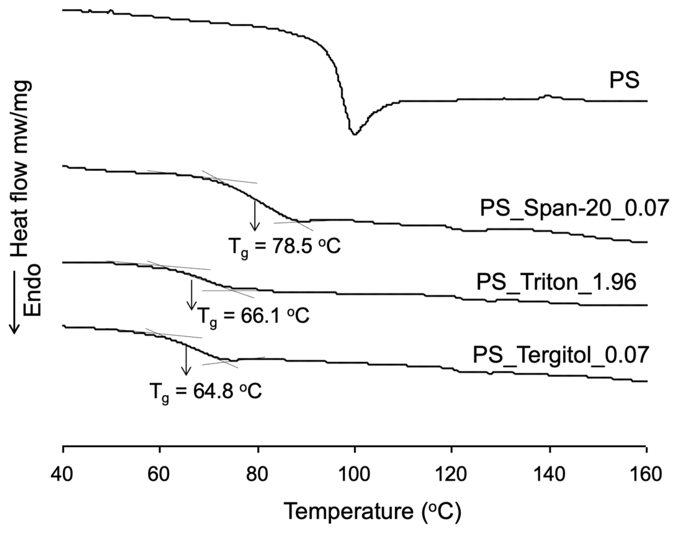
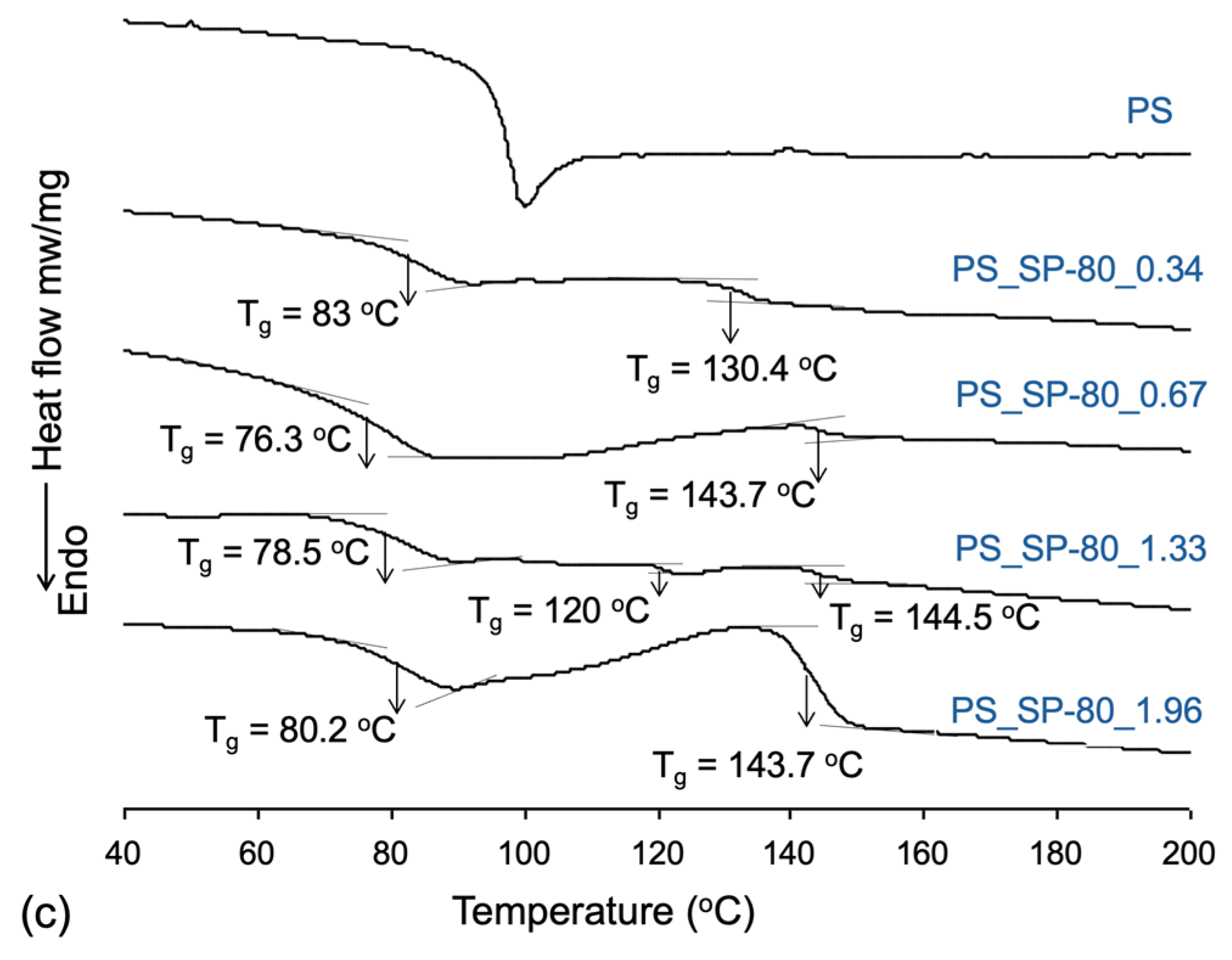
The addition of a surfactant to PS lowers its glass transition temperature and its endothermic properties due to the increased free volume within the PS film bulk. Furthermore, CTAB molecules undergo ionic association and Span-80s form hydrogen-bond clusters, respectively, at the film–air interface, driven by their linear tail structures, thereby contributing to the strength of endothermic transitions.
iv.
The Span-80-induced surface pattern, represented by bowl-shaped holes, was utilized as a microreactor to investigate the impact of its hydrophilic curvature at a micron-scale on the following two deposition reactions.
*
Recrystallization of acrylamide achieved a pure monoclinic lattice, attributed to hydrogen-bonding-initiated seeding.
*
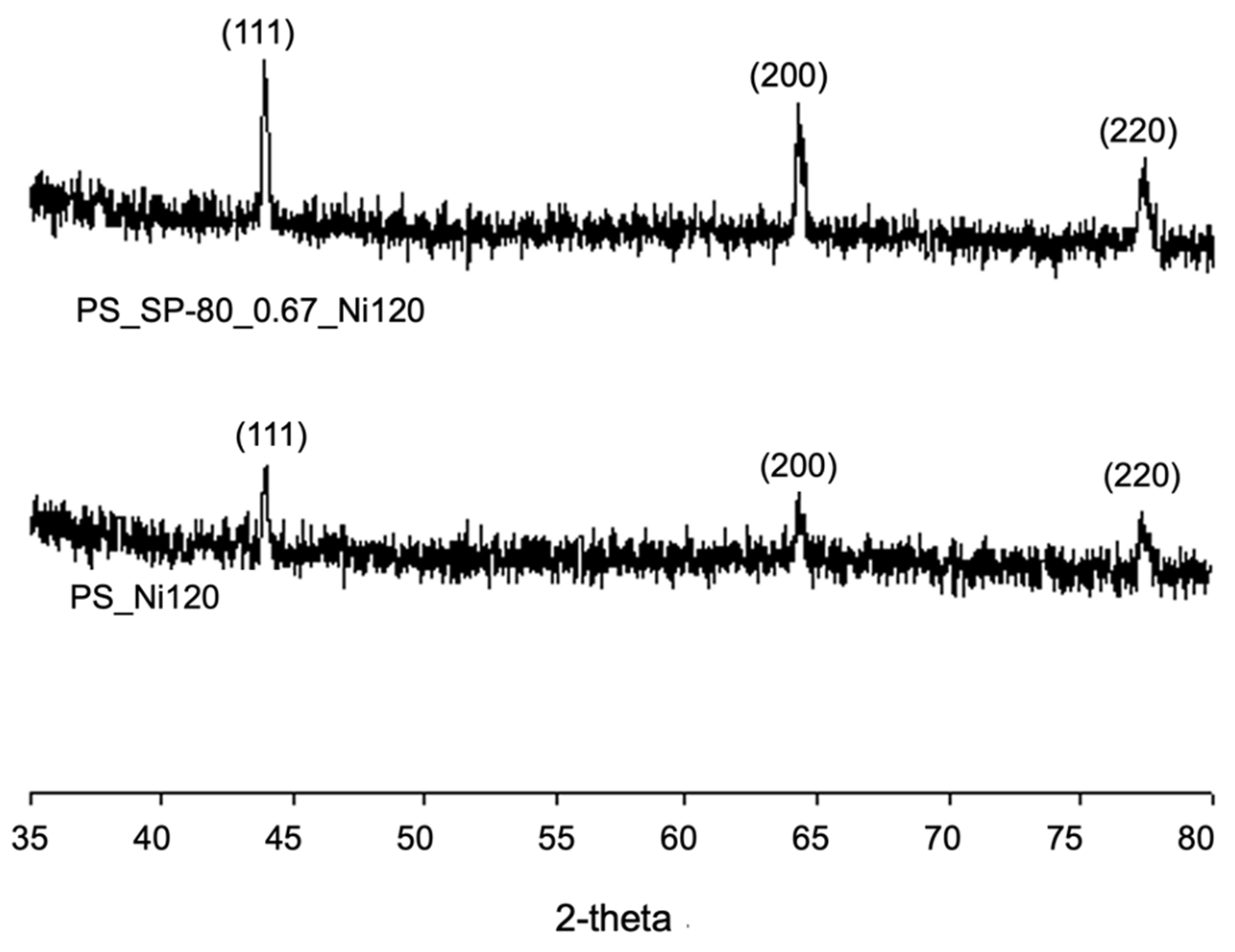
Electroless Ni plating deposited Ni-P alloy dendrites with a high P % content, which was attributed to the spatial confinement of the surface hole chamber.
v.
Reduction of the [Cu(4VPy)2]2+ complex ion inside the dispersed aqueous droplets of the Span-80-stabilized emulsion yields a PS film with uniformly embedded Cu nanoparticles (<16 nm), whose surface plasmon resonance appear at a lower frequency than the known ones, manifesting the micro-templating effect.

Supplementary Materials

The following supporting information can be downloaded at: https://www.mdpi.com/article/10.3390/coatings14080956/s1, Figure S1: AFM Section analysis of the PS_Tergitol_0.07 film, and the PS_Triton_1.96 film; Figure S2: AFM Section analysis of the PS_Span-20_0.07 film; Figure S3: AFM section analysis of the PS_Span-80_0.67_AM30 film; Figure S4: Comparison of the IR spectrum of the PS_Span-80_0.67_AM30 film with those of its two precursors; Figure S5: X-ray diffraction pattern of the PS-SP80-44-AM15 film; Figure S6: The SEM image of the surface of the control sample, Brass_Ni60, prepared by plating a brass sheet for 30 s under the same EN condition; Figure S7: The EDX spectrum taken from Ni-P needles inside an arbitrarily selected hole; Figure S8: Comparison of the FT-IR spectrum of PS_Span-80_0.67_Cu0.7_w with that of the substrate film PS_Span-80_0.67. The matching shows the presence of the residues of hydrazine and 4VPy.

Author Contributions

Conceptualization, L.H.; methodology, L.H. and Z.T.H.; validation, L.H. and Z.T.H.; formal analysis, Z.T.H.; investigation, Z.T.H.; resources, L.H.; data curation, Z.T.H.; writing—original draft preparation, Z.T.H.; writing—review and editing, L.H.; visualization, L.H.; supervision, L.H.; project administration, L.H.; funding acquisition, L.H. All authors have read and agreed to the published version of the manuscript.

Funding

This research received no external funding.

Institutional Review Board Statement

Not applicable.

Informed Consent Statement

Not applicable.

Data Availability Statement

Master’s thesis by Zin Thwe Hauan: “Template effects of micro-pores created by the self-assembly of surfactant molecules in polystyrene thin film”. 2003. https://scholarbank.nus.edu.sg/handle/10635/13565. (Issue date: 3 December 2003).

Acknowledgments

The authors acknowledge the administrative and logistical support provided by the Chemical and Biomolecular Engineering Department of the National University of Singapore.

Conflicts of Interest

The authors declare no conflict of interest.

References

  1. Steward, P.A.; Hearn, J.; Wilkinson, M.C. An overview of polymer latex film formation and properties. Adv. Colloid Interface Sci. 2000, 86, 195–267. [Google Scholar] [CrossRef]
  2. Brito, E.L.; Ballard, N. Film formation of hard-core/soft-shell latex particles. J. Polym. Sci. 2023, 61, 410–421. [Google Scholar] [CrossRef]
  3. Swarup, S.; Schoff, C.K. A survey of surfactants in coatings technology. Prog. Org. Coat. 1993, 23, 1–22. [Google Scholar] [CrossRef]
  4. Enekvist, M.; Liang, X.; Zhang, X.; Dam-Johansen, K.; Kontogeorgis, G.M. Computer-aided design and solvent selection for organic paint and coating formulations. Prog. Org. Coat. 2022, 162, 106568. [Google Scholar] [CrossRef]
  5. Walker, J.; Schofield, A.B.; Koutsos, V. Nanostructures and thin films of poly(ethylene glycol)-based surfactants and polystyrene nanocolloid particles on mica: An atomic force microscopy study. Coatings 2023, 13, 1187. [Google Scholar] [CrossRef]
  6. Karthaus, O.; Ijiro, K.; Shimomura, M. Ordered self-assembly of nanosize polystyrene aggregates on mica. Chem. Lett. 1996, 25, 821–822. [Google Scholar] [CrossRef]
  7. Wang, M.; Zhang, L. Hole pattern in polymer films and its template effect on the growth of gold particles. Thin Solid Film 2000, 359, 82–87. [Google Scholar] [CrossRef]
  8. Sato, Y.; Singai, T.; Hatakeyama, K.; Wakaki, S.; Takahashi, T.; Nasu, A. Observation of OW·WO emsion coating film formed by doctor blade applicator. J. Coat. Technol. Res. 2022, 19, 1117–1126. [Google Scholar] [CrossRef]
  9. Ookura, R.; Nishida, J.; Nishikawa, T.; Shimomura, M. Stabilization of micropatterned polymer films as artificial extracellular matrices for tissue engineering. Mol. Cryst. Liq. Cryst. 1999, 337, 461–464. [Google Scholar] [CrossRef]
  10. Choi, S.; Min, S.-B.; Jeon, D.; Kim, C.B. Marangoni-driven patterning in polymer thin film supported on shrinking substrate for resolution enhancement. Macromol. Chem. Phys. 2023, 224, 2300035. [Google Scholar] [CrossRef]
  11. Bormashenko, E.; Pogreb, R.; Stanevsky, O.; Bormashenko, Y.; Stein, T.; Gaisin, V.-Z.; Cohen, R.; Gendelman, O.V. Mesoscopic patterning in thin polymer films formed under the fast dip-coating process. Macromol. Mater. Eng. 2005, 290, 114–121. [Google Scholar] [CrossRef]
  12. Müller-Buschbaum, P. Dewetting and pattern formation in thin polymer films as investigated in real and reciprocal space. J. Phys. Condens. Matter. 2003, 15, R1549–R1582. [Google Scholar] [CrossRef]
  13. Liu, C.X.; Lang, W.Z.; Shi, B.B.; Guo, Y.J. Fabrication of ordered honeycomb porous polyvinyl chloride (PVC) films by breath figures method. Mater. Lett. 2013, 107, 53–54. [Google Scholar] [CrossRef]
  14. Xue, L.; Han, Y. Pattern formation by dewetting of polymer thin film. Prog. Polym. Sci. 2011, 36, 269–293. [Google Scholar] [CrossRef]
  15. Telford, A.M.; Thickett, S.C.; Neto, C. Functional patterned coatings by thin polymer film dewetting. J. Colloid Interface Sci. 2017, 507, 453–469. [Google Scholar] [CrossRef]
  16. Escalé, P.; Rubatat, L.; Billon, L.; Save, M. Recent advances in honeycomb-structured porous polymer films prepared via breath figures. Eur. Polym. J. 2012, 48, 1001–1025. [Google Scholar] [CrossRef]
  17. Peng, J.; Han, Y.; Fu, J.; Yang, Y.; Li, B. Formation of regular hole pattern in polymer films. Macromol. Chem. Phys. 2003, 204, 125–130. [Google Scholar] [CrossRef]
  18. Lv, G.; Tian, H.; Shao, J.; Yu, D. Pattern formation in thin polymeric films via electrohydrodynamic patterning. RCS Adv. 2022, 12, 9681–9697. [Google Scholar] [CrossRef]
  19. Vyas, J.; Pandey, R.K. Determination of HLB value by saponification method: A brief review. Nat. J. Pharm. Sci. 2021, 1, 23–24. [Google Scholar]
  20. Nollet, M.; Boulghobra, H.; Calligaro, E.; Rodier, J.D. An efficient method to determine the Hydrophile-Lipophile Balance of surfactants using the phase inversion temperature deviation of CiEj/n-octane/water emulsions. Int. J. Cosmetic Sci. 2019, 41, 99–108. [Google Scholar] [CrossRef]
  21. Poornima Kalyanram, P.; Patricia Valenzuela, P.; Anju R Gupta, A.R. 2017. Aerosol-Ot Stabilized Micro and Nano-Scale Emulsions for Pharmaceutical Formulations. Org. Med. Chem. Int. J. 2017, 4, 88–90. [Google Scholar]
  22. Hensel, J.K.; Carpenter, A.P.; Ciszewski, R.K.; Schabes, B.K.; Kittredge, C.T.; Moore, F.G.; Richmond, G.L. Molecular characterization of water and surfactant AOT at nanoemulsion surfaces. Proc. Natl. Acad. Sci. USA 2017, 114, 13351–13356. [Google Scholar] [CrossRef]
  23. Barut, K.D.; Coşkun Ari, F.F.; Öner, F. Development and characterization of a cationic emulsion formulation as a potential pDNA carrier system. Turk. J. Chem. 2005, 29, 4. [Google Scholar]
  24. Dos Santos, A.Z.M.; Morais, W.A.; de Sousa, E.A.; Dantas Neto, A.A.; Dantas, T.N.C.; Pereira, M.R.; Fonseca, J.L.C. Rheology of inverse emulsions with chitosan, ctab, and cyclohexane. Soft Mater. 2009, 7, 185–197. [Google Scholar] [CrossRef]
  25. Liu, Z.; Yin, Y.; Eginligil, M.; Wang, L.; Liu, J.; Huang, W. Two-dimensional conjugated microporous polymer films: Fabrication strategies and potential applications. Polym. Chem. 2021, 12, 807–821. [Google Scholar] [CrossRef]
  26. Sarabia-Vallejos, M.A.; Cerda-Iglesias, F.E.; Pérez-Monje, D.A.; Acuña-Ruiz, N.F.; Terraza-Inostroza, C.A.; Rodríguez-Hernández, J.; González-Henríquez, C.M. Smart polymer surfaces with complex wrinkled patterns: Reversible, non-planar, gradient, and hierarchical structures. Polymers 2023, 15, 612. [Google Scholar] [CrossRef]
  27. Zhang, X.; Yang, L.; Wang, F.; Cheng, Z.; Liang, H. Wrinkled surface microstructure for enhancing the infrared spectral performance of radiative cooling. Opt. Express 2021, 29, 11416–11432. [Google Scholar] [CrossRef]
  28. Crut, A.; Maioli, P.; Fatti, N.D.; Vallée, F. Acoustic vibrations of metal nano-objects: Time-domain investigations. Phy. Rep. 2015, 549, 1–43. [Google Scholar] [CrossRef]
  29. Paulo, B.B.; Andreola, K.; Taranto, O.; Ferreira, A.D.; Prata, A.S. Coating approach for a phase change material (PCM). Powder Technol. 2019, 341, 147–156. [Google Scholar] [CrossRef]
  30. Yim, Y.-J.; Rhee, K.Y.; Park, S.-J. Electromagnetic interference shielding effectiveness of nickel-plated MWCNTs/high-density polyethylene composites. Compos. Part B Eng. 2016, 98, 120–125. [Google Scholar] [CrossRef]
  31. Fox, C.B.; Lin, S.; Sivananthan, S.J.; Dutill, T.S.; Forseth, K.T.; Reed, S.G.; Vedvick, T.S. Effects of emulsifier concentration, composition, and order of addition in squalene-phosphatidylcholine oil-in-water emulsions. Pharm. Dev. Technol. 2011, 16, 511–519. [Google Scholar] [CrossRef]
  32. Bournigault-Nuquet, A.; Couderc, S.; Bibette, J.; Baudry, J. Patterning of a drying emulsion film. Langmuir 2021, 37, 8924–8928. [Google Scholar] [CrossRef]
  33. Ramisetty, K.A.; Pandit, A.B.; Gogate, P.R. Ultrasound assisted preparation of emulsion of coconut oil in water: Understanding the effect of operating parameters and comparison of reactor designs. Chem. Eng. Proc. 2015, 88, 70–77. [Google Scholar] [CrossRef]
  34. L’Estimé, M.; Schindler, M.; Shahidzadeh, N.; Bonn, D. Droplet size distribution in emulsions. Langmuir 2024, 40, 275–281. [Google Scholar] [CrossRef]
  35. Shyichuk, A.; Ziółkowska, D.; Szulc, J. Coagulation of hydrophobic ionic associates of cetyltrimethylammonium bromide and carrageenan. Molecules 2023, 28, 7584. [Google Scholar] [CrossRef]
  36. Zhang, T.; Xu, G.; Li, Z.-F.; Regev, O.; Maddumaarachchi, M.; Blum, F.D. PS/CTAB/silica composites from room temperature polymerization of high internal phase emulsion gels. J. Colloid Interface Sci. 2015, 451, 161–169. [Google Scholar] [CrossRef]
  37. Tan, Z.; Zhang, Y.; Dai, C.; Li, L.; Li, Y.; Xie, X. Investigation of AOT/isooctane/water reverse microemulsion system with the presence of different mass ratios of SDS: Conductivity and water solubilization. Colloids Surf. A Physicochem. Eng. Asp. 2022, 648, 129271. [Google Scholar] [CrossRef]
  38. Zhao, Y.; Urban, M.W. Polystyrene/Poly(n-butyl acrylate) Latex Blend Coalescence, Particle Size Effect, and Surfactant Stratification:  A Spectroscopic Study. Macromolecules 2000, 33, 7573–7581. [Google Scholar] [CrossRef]
  39. Schott, H. Hydrophilic-lipophilic balance, solubility parameter, and oil-water partition coefficient as universal parameters of nonionic surfactants. J. Pharm. Sci. 1995, 84, 1215–1222. [Google Scholar] [CrossRef]
  40. Stefanis, E.; Panayiotou, C. Prediction of Hansen solubility parameters with a new group-contribution method. Int. J. Thermophys. 2008, 29, 568–585. [Google Scholar] [CrossRef]
  41. Kato, Y.; Tsutsumi, S.; Fujiwara, N.; Yamamoto, H. Measurements of the Hansen solubility parameters of mites and cockroaches to improve pest control applications. Heliyon 2019, 5, e01853. [Google Scholar] [CrossRef] [PubMed]
  42. Schott, H. Solubility Parameter and hydrophilic-lipophilic balance of nonionic surfactants. J. Pharm. Sci. 1984, 73, 790–792. [Google Scholar] [CrossRef] [PubMed]
  43. Mieczkowski, R. The determination of the solubility parameter components of polystyrene by partial specific volume measurements. Eur. Polym. J. 1988, 24, 1185–1189. [Google Scholar] [CrossRef]
  44. Law, K.-Y. Contact angle hysteresis on smooth/flat and rough surfaces. interpretation, mechanism, and origin. Acc. Mater. Res. 2022, 3, 1–7. [Google Scholar] [CrossRef]
  45. Pierri, E.; Dalas, E. The precipitation of ferric phosphate on porous polymer. Colloids Surf. A Physicochem. Eng. Asp. 1998, 139, 335–340. [Google Scholar] [CrossRef]
  46. Ott, A.W.; Chang, R.P.H. Atomic layer-controlled growth of transparent conducting ZnO on plastic substrates. Mater. Chem. Phys. 1999, 58, 132–138. [Google Scholar] [CrossRef]
  47. Yin, X.; Hong, L.; Chen, B.-H.; Ko, T.-M. Modelling the stability of electroless plating bath—Diffusion of nickel colloidal particles from the plating frontier. J. Colloid Interface Sci. 2003, 262, 89–96. [Google Scholar] [CrossRef]
  48. Gong, D.; Cai, J.; Li, X.; Zhang, D. Magnetic helical microswimmers made by spirulina through electroless nickel plating. In Proceedings of the 2018 IEEE 13th Annual International Conference on Nano/Micro Engineered and Molecular Systems (NEMS), Singapore, 22–26 April 2018; pp. 515–518. [Google Scholar] [CrossRef]
  49. Sun, Z.; Huang, J.; Wang, L.; Zhang, X.; Li, M.; Tang, B. Method for electroless nickel plating on poly(ethylene terephthalate) substrate modified with primer and self-assembled monolayer. J. Mater. Sci. Mater. Electron. 2015, 26, 10132–10137. [Google Scholar] [CrossRef]
  50. Zhang, Y.; Tan, K.L.; Yang, G.H.; Kang, E.T.; Neoh, K.G. Electroless plating of copper and nickel via a Sn-free process on polyimide films modified by surface graft polymerization with 1-vinylimidazole. J. Electrochem. Soc. 2001, 148, C574. [Google Scholar] [CrossRef]
  51. Ramyadevi, J.; Jeyasubramanian, K.; Marikani, A.; Rajakumar, G.; Rahuman, A.A.; Santhoshkumar, T.; Kirthi, A.V.; Jayaseelan, C.; Marimuthu, S. Copper nanoparticles synthesized by polyol process used to control hematophagous parasites. Parasitol. Res. 2011, 109, 1403–1415. [Google Scholar] [CrossRef]
  52. Amaliyah, S.; Pangesti, D.P.; Masruri, M.; Sabarudin, A.; Sumitro, S.B. Green synthesis and characterization of copper nanoparticles using Piper retrofractum Vahl extract as bioreductor and capping agent. Heliyon 2020, 6, e04636. [Google Scholar] [CrossRef] [PubMed]
Figure 1. The chemical structures of the six surfactants tested in the present investigation.
Coatings 14 00956 g001
Figure 2. SEM images of the patterned surface of (a) the PS_CTAB_0.67 film and (b) the control, PS film. (c,d) A schematic illustration of the CTAB array at the water–organic interface in the w/o emulsion, and the CTAB micelle formed in water, respectively.
Coatings 14 00956 g002
Figure 3. (a) The AFM section analysis over the surface of PS_CTAB_0.67. (b) The 3D contour of the pristine PS film, which shows a thickness of 150 nm.
Coatings 14 00956 g003
Figure 4. DSC diagrams of the PS_CTAB_0.67 and PS films, which were obtained using a scanning rate of 10 °C/min and the same sample mass (10 mg).
Coatings 14 00956 g004
Figure 5. (a) SEM image of the patterned surface of the PS_AOT_1.96 film, revealing an orderly assembly of M-shaped units, (b) AFM section analysis to display the surface profile of the film, and (c) a schematic illustration of the formation of an M-shaped unit comprising PS and AOT.
Coatings 14 00956 g005
Figure 6. DSC diagrams of PS_AOT_1.96 and PS films were obtained under the same analytical conditions as described above.
Coatings 14 00956 g006
Figure 7. SEM images of the patterned PS surfaces of (a) PS_Tergitol_0.07, (b) PS_Triton_1.96, (c) PS_Span-20_0.07, and (d) PS_Span-80_0.67.
Coatings 14 00956 g007
Figure 8. DSC diagrams of the three non-ionic surfactant patterned films, which were obtained under the same analytical conditions as described above.
Coatings 14 00956 g008
Figure 9. (a) AFM 3D image of the film PS_Span-80_0.67; (b) AFM section image of the film PS_Span-80_0.67; (c) DSC diagrams of the films PS_Span-80_xxx%, which were obtained under the same analytical conditions as described above.
Coatings 14 00956 g009aCoatings 14 00956 g009b
Figure 10. (a) SEM image of the AM crystallite-deposited PS_Span-80_0.67 film and (b) the corresponding AFM 3D image.
Coatings 14 00956 g010
Figure 11. XRD patterns of PS_Span-80_0.67, PS_Span-80_0.67_AM30, and the AM powder obtained from recrystallization in a petri dish, as mentioned in Section 2.3.
Coatings 14 00956 g011
Figure 12. SEM images of the EN-plated surfaces: (a) PS_Span-80_0.67_Ni60, and (b) PS_Span-80_0.67_Ni120.
Coatings 14 00956 g012
Figure 13. XRD patterns of the Ni-P alloy layers deposited on the two PS surfaces.
Coatings 14 00956 g013
Figure 14. TEM images of the Cu nanoparticle-embedded PS film matrixes: (a) PS_Span-80_0.67_Cu0.7_w/o, (b) PS_Span-80_0.67_Cu0.7_w, (c) PS_Span-80_0.67_Cu0.7_w/rd, and (d) PS _Cu0.7_w. Inset: XRD image of PS_Span-80_0.67_Cu0.7_w.
Coatings 14 00956 g014
Figure 15. The UV–Vis spectra of the three PS films obtained from the three electroless copper deposition trials.
Coatings 14 00956 g015
Table 1. The surfactants utilized for the preparation of w/o emulsions in this study.
Commercial
Name
Charge TypeChemical NameHLB Value a/Solubility b (g/L)
AOTAnionicSodium dioctyl sulfosuccinate10.5/14
CTABCationicn-Hexadecyl trimethyl ammonium bromide10/36.4
Span-80Non-ionicSorbitane mono-oleate4.3 b/insoluble
Span-20Non-ionicSorbitane mono-laurate8.6/0.2
Triton X-100Non-ionict-Octylphenoxypolyethoxyethanol13.5/soluble
Tergitol NP-12Non-ionicNonylphenol ethoxylate13.8/soluble
a. The calculated HLB values = wt. % of ethylene-oxide/5 for the four non-ionic surfactants. b. The solubility in water at ambient temperature.
Table 2. Effect of the concentration of CTAB on the average hole diameters of PS films.
Wt. % of CTAB in PS FilmPore Diameters (μm)Average Hole Diameters (μm)
0.073.3–6.14.7
0.142.2–3.32.8
0.671.9–2.12.0
1.33--
Table 3. Root mean square (RMS) roughness of the three typical films.
Emulsion-Derived PS FilmRMS Roughness (nm)
PS_CTAB_0.6710.2
PS_AOT_1.963.2
PS_Span-80_0.6721.7
PS_Triton_1.968.3
PS_Tergitol_0.0710.2
PS_Span-20_0.6711.7
Table 4. Solubility parameters of the hydrocarbon tails of the six surfactants based on the group-contribution method.
Hydrocarbon TailNo. of the First-Order Groups a, and Their Corresponding Ci bδtail
(MPa)0.5
δsurf
(MPa)0.5
-CH3-CH2--CH<-CH=CH-ACHAC
−0.9714−0.02690.64500.00480.11050.8446
CTAB114 18.3121.64 c
AOT482 16.06-
Span-80112 1 18.4023.71 d
Span-2019 18.5226.04
Tergitol NP-1218 4120.6026.57
Triton X-10017 4120.6426.37
a This type of groups does not have a resonance effect. b They are obtained from reference [40]. c It is obtained from [41]. d It is obtained from [42], and so are the three data underneath in this column.
Table 5. The XRD pattens of the Ni-P alloy deposition layers on the two different PS films.
SampleCrystallographic Planes and 2θ Angles
(111)(200)(220)
PS_Span-80_0.67_Ni12044.1664.2877.52
PS_Ni12044.4164.3877.62
References [42,43]44.5452.1076.46
Table 6. Preparation of PS film with embedded copper NPs.
Film FormedCP (mL) aDP (aq. soln., mL) avol.% of aq. Phase
Copper Source aq. bHydrazine c
PS_Span-80_0.67_Cu0.7_w/o d10.480.7 (CuSO4)0.7/in situ11.78
PS_Span-80_0.67_Cu0.7_w10.480.7 [Cu(4VPy)2SO4 plus free 4VPy]0.7/in situ11.78
PS_Span-80_0.67_Cu0.7_w/rd10.480.7 [Cu(4VPy)2SO4]1.0/post16.02
a. CP and DP for continuous phase and dispersed phase, respectively; b. the concentration is 1 M; c. hydrazine is a reducing agent, and its concentration is 54.4 wt.%; d. refer to Section 2.5 for the definition of the suffix.
Disclaimer/Publisher’s Note: The statements, opinions and data contained in all publications are solely those of the individual author(s) and contributor(s) and not of MDPI and/or the editor(s). MDPI and/or the editor(s) disclaim responsibility for any injury to people or property resulting from any ideas, methods, instructions or products referred to in the content.

